


Überspannungsschutz
Bedienungs- und Montageanleitung
Spannungsgesteuerte Abgrenzeinheit
VCSD 40 IP65
DE GB
Publication No. 1880/
Update 09.17 Mat-No. 3006917
www.dehn.de
© Copyright 2017 DEHN + SÖHNE

Inhaltsverzeichnis
1. Sicherheitshinweise......................................................................3
2. Beschreibung................................................................................4
2.1 Anwendung............................................................................................5
2.2 Funktionsbeschreibung. ..........................................................................6
3. Montage und Anschluss................................................................7
3.1 Wandmontage........................................................................................7
3.2 Demontage der Abdeckplatte..................................................................8
3.3 Anschluss der Hauptleitungen.................................................................9
3.4 An- bzw. Abklemmen der Steuerleitungen ...............................................10
4. Inbetriebnahme............................................................................11
4.1 Ablauf....................................................................................................11
4.1.1 Batterie einlegen ....................................................................................11
4.1.2 Externe Spannungversorgung..................................................................11
4.1.3 Entfernen der Brücke „VCSD aus“..........................................................11
4.1.4 Einstellen der Ansprechschwelle..............................................................12
4.2 LED-Anzeigen.........................................................................................13
4.3 Fehlerstatus............................................................................................15
4.3.1 Fehlerzustände........................................................................................15
4.3.2 Fehlerstatus-Relais..................................................................................16
5. Selbsttest......................................................................................17
5.1 Abklemmen............................................................................................17
5.2 Entladen.................................................................................................17
5.3 Externe Spannungsversorgung ................................................................17
6. VCSD aus.......................................................................................18
7. Analog OUT...................................................................................19
8. Externe Spannungsversorgung.....................................................20
9. USB-Schnittstelle..........................................................................20
10. Technische Daten..........................................................................21
11. Derating für den stationären Ableitstrom....................................22
12. Diagnose / Fehleranalyse..............................................................23
13. Prinzipdarstellung der Betriebsmodi............................................24
2
IEC 60417-6182:
Installation,
electrotechnical expertise
1. Sicherheitshinweise
Die Montage der Spannungsgesteuerten Abgrenzeinheit
VCSD 40 IP65
darf nur durch eine Elektrofachkraft erfolgen.
Die nationalen Vorschriften und Sicherheitsbestimmungen sind zu beachten (
DIN VDE 0105-100)
AfK-Empfehlung Nr. 3, Nr. 5 und Nr. 11.
Vor der Montage ist die Abgrenzeinheit
VCSD 40 IP65
Sollte eine Beschädigung oder ein sonstiger Mangel festgestellt werden, darf die Abgrenzeinheit
40 IP65
Der Einsatz der Abgrenzeinheit
nicht montiert werden.
VCSD 40 IP65
ist nur im Rahmen der in dieser Bedienungs- und
auf äußere Beschädigung zu kontrollieren.
VCSD
Montageanleitung genannten und gezeigten Bedingungen zulässig.
Bei Belastungen, die über den ausgewiesenen Werten liegen, können die Abgrenzeinheit
sowie die daran angeschlossenen elektrischen Betriebsmittel zerstört werden.
an der Abgrenzeinheit
VCSD 40 IP65
führen zum Erlöschen des Gewährleistungsanspruches.
Eingriffe und Veränderungen
VCSD 40 IP65
Vor Beginn jeder elektrischen Installation und Montage ist die Anwendungsnorm DIN VDE 0105-100 zum
„Arbeiten an elektrischen Anlagen und Betriebsmitteln“ zu beachten.
Nach Abklemmen des Pipeline- und PE-Anschlusses die Kondensatoren für
mindestens 10 Sekunden durch Drücken des Tasters SVN 311 entladen!
Achtung:
Leuchtet keine LED am Gerät kann durch Anlegen einer
ext. Spannung (9 ... 32V
Tiefenentladung der Batterie vorliegt!
) geprüft werden, ob eine
DC
Achtung:
Bei der Montage und beim Austausch des
keine Ströme fließen, die zu einer Lichtbogenbildung führen können.
Die Arbeiten am
Vor dem An- bzw. Abklemmen der Hauptleitungen muss das Gerät in
den manuellen Abschaltbetrieb gebracht werden!
Setzen Sie dazu, bei noch eingelegter Batterie, eine „VCSD aus“ Brücke am
VCSD 40 IP65
durchgeführt werden!
Digitalen Eingang ein!
dürfen nur im spannungsfreien Zustand
VCSD 40 IP65
ist sicherzustellen, dass
3

2. Beschreibung
Die Spannungsgesteuerte Abgrenzeinheit VCSD 40 IP65 ist ein aus einem Überspannungsereignis
heraus gesteuerter Kurzschlußschalter für transiente, temporäre und stationäre Überspannungen
(siehe Fig.1). Derartige Überspannungen mit bestimmter Zeitdauer oder bestimmtem Spannungspegel aktivieren dem Ereignis zugeordnete Funktionseinheiten des Kurzschlußschalters und schließen
die Überspannung für deren Zeitdauer (ohne Beeinflussung des DC-Potentials) kurz. Dadurch werden
Überspannungen begrenzt und ihre Auswirkungen im unmittelbaren Einsatzbereich der
Abgrenzeinheit VCSD 40 IP65 auf ein ungefährliches, sicherheitstechnisch vertretbares Maß reduziert.
Im Einzelnen werden durch das koordinierte Zusammenwirken der Funktionseinheiten der
Abgrenzeinheit VCSD 40 IP65 folgende überspannungsbedingte Auswirkungen erfasst:
Vermeidung undefinierter, blitzbedingter Durch- und Überschläge von
Isolationsstrecken
Überspannungen durch Blitzereignisse werden begrenzt, die in diesem Zusammenhang auftretenden
Blitzströme werden gegen die örtliche Erde abgeleitet (Sachschutz).
Vermeidung gefährlicher Berührungsspannung an zugänglichen Stellen
Gefährliche Berührungsspannungen werden für die Zeitdauer ihres Auftretens auf Werte unterhalb
der höchstzulässigen Berührungsspannung begrenzt (Personenschutz gemäß AfK-Empfehlung Nr. 3).
Vermeidung der Zerstörung von Komponenten
Sowohl transiente (z.B. blitzbedingte) als auch periodisch wiederkehrende Überspannungen werden
auf für Komponenten ungefährliche Werte begrenzt (Geräteschutz).
2000
1500
1250
1000
940
Spannung [V]
660
400
60
50
Grenzwerte nach DGMK
Forschungsbericht 609
1)
Grenzwerte nach
AfK-3/GW22
2)
0
1 20 100 200 > 200
1)
AfK: Arbeitsgemeinschaft DVGW/VDE für Korrosionsfragen
2)
DGMK: Deutsche Wissenschaftliche Gesellschaft für Erdöl, Erdgas und Kohle e.V.
Fig. 1 Spannungsgrenzwerte
4
Zeit [ms]

2.1 Anwendung
Die Spannungsgesteuerte Abgrenzeinheit Typ VCSD - Voltage-controlled smart decoupling
device wird in elektrischen Systemen mit einem hohen Ausbreitungs- und Vernetzungsgrad, die durch
Fremdspannungen von unterschiedlichen Störquellen (z.B. Hochspannungssysteme,
Bahnstromversorgungs-syteme, Niederspannungssysteme, Blitzbeeinflussung) beeinflusst werden,
eingesetzt (siehe auch
Fig. 2.1) und Fig. 2.2, Seite 6).
Einsatz in KKS-Anlagen entsprechend der AfK-Empfehlung Nr. 3, Nr. 5 und 11 bzw. Anlagen mit
ähnlichen Anforderungen
Isolierte Pipelineabschnitte
Offene Erdung von Kabelschirmen an zugänglichen Stellen
Korrosionsfreier Zusammenschluss von erdgebetteten metallenen Anlagen (z. B. Erdungsanlagen) mit
einem Fundamenterder
Verbindung verschiedener, getrennt wirkender Erdungssysteme (z. B. Gebäudefundamenterder und
eine getrennte Messerde)
Pipeline
Transienter
Schalter
TU
Fig. 2.1 Funktionsgruppen
Ansteuer- und
Auswerteeinheit
CU
Dauerstromtragfähiger
Schalter
PU
5
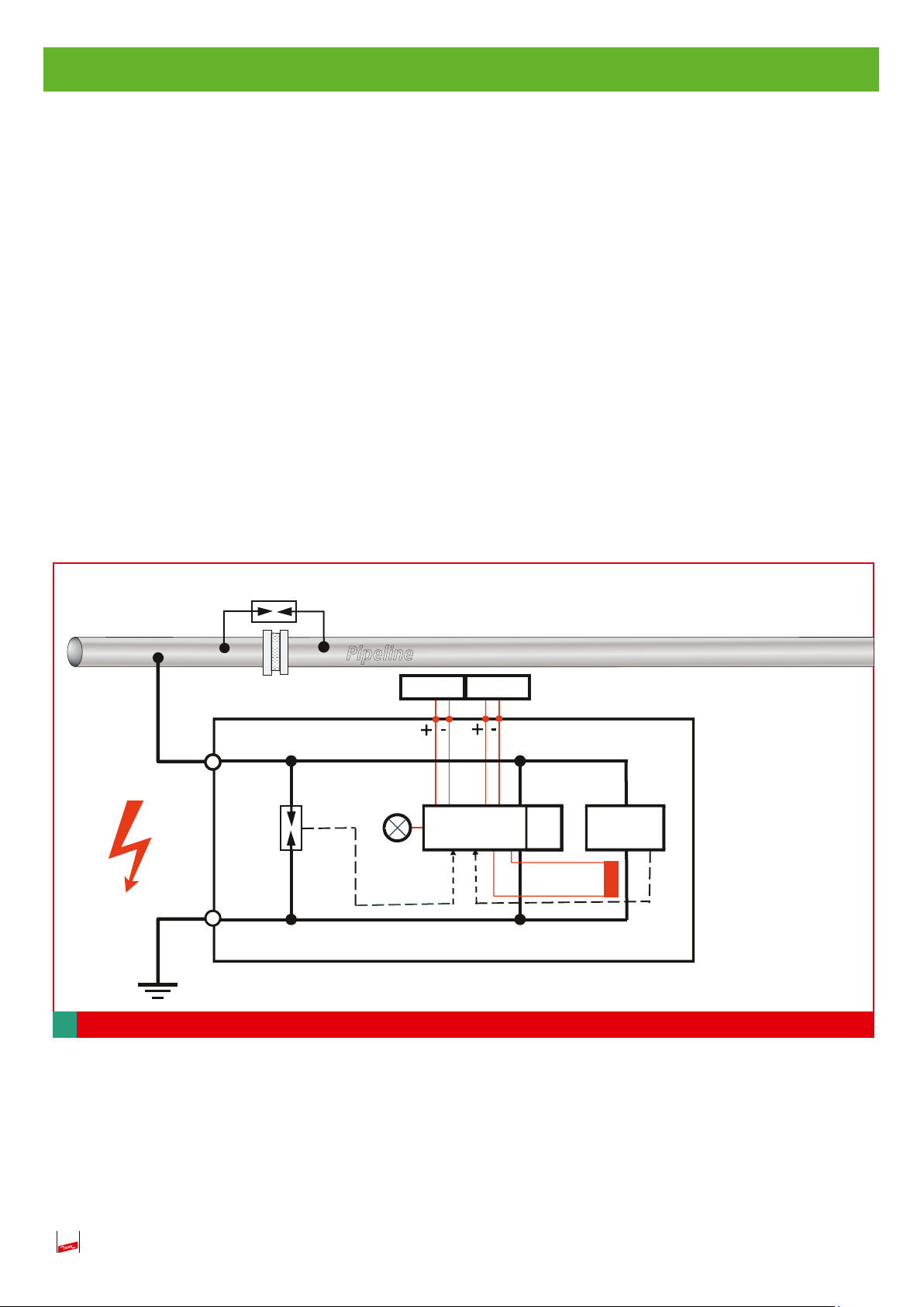
2.2 Funktionsbeschreibung der Abgrenzeinheit
Transiente und temporäre / stationäre Überspannungen sind in dem zu betrachtenden Zeitbereich
durch eine Einzelkomponente nicht wirkungsvoll zu begrenzen.
Komponenten zur Begrenzung energiereicher Transienten, wie sie bei Blitzbeeinflussungen entstehen,
bestehen aus hochleistungsfähigen Funkenstrecken. Die charakteristische Eigenschaften von Funkenstrecken ist ihre kurze Ansprechzeit (typisch 100ns) und ihr hohes Energieableitvermögen bei Impulsbelastung im µs-Bereich (z.B. einige 10kA (10/350
µs)). Länger andauernde Ableitvorgänge
(stationärer bzw. temporärer Zeitbereich) führen zu thermischen Überlastung. Deshalb muss bei
solchen Vorgängen eine „Entlastungsschaltung“ den Ableitvorgang „übernehmen“, d.h. der Ableitstrom über die Funkenstrecke muß vollständig auf die „Entlastungsschaltung“ kommutieren, sobald
die Überspannung den transienten Zeitbereich übersteigt. Diese Entlastungsschaltung (PU) besteht
bei der Abgrenzeinheit VCSD 40 IP65 aus Leistungshalbleitern, die zum Übergangszeitpunkt
transient zu temporär / stationär über eine koordinierende Auswerteelektronik zugeschaltet werden.
Die Auswerteelektronik (CU) wertet verschiedene Sensorsignale aus und koordiniert so das Zusammenspiel der einzelnen Funktionseinheiten (siehe Fig. 2.2).
EXFS
1
FM-Kontakt
TU
2
Fig. 2.2 Funktionseinheiten
Pipeline
H
digital.
I/O
CU
analog
PS
PU
PU: Power Unit
CU: Control Unit
PS: Power Supply
TU: Transient Unit
EXFS: Ex-Trennfunkenstrecke
6

3. Montage und Anschluss
3.1 Wandmontage
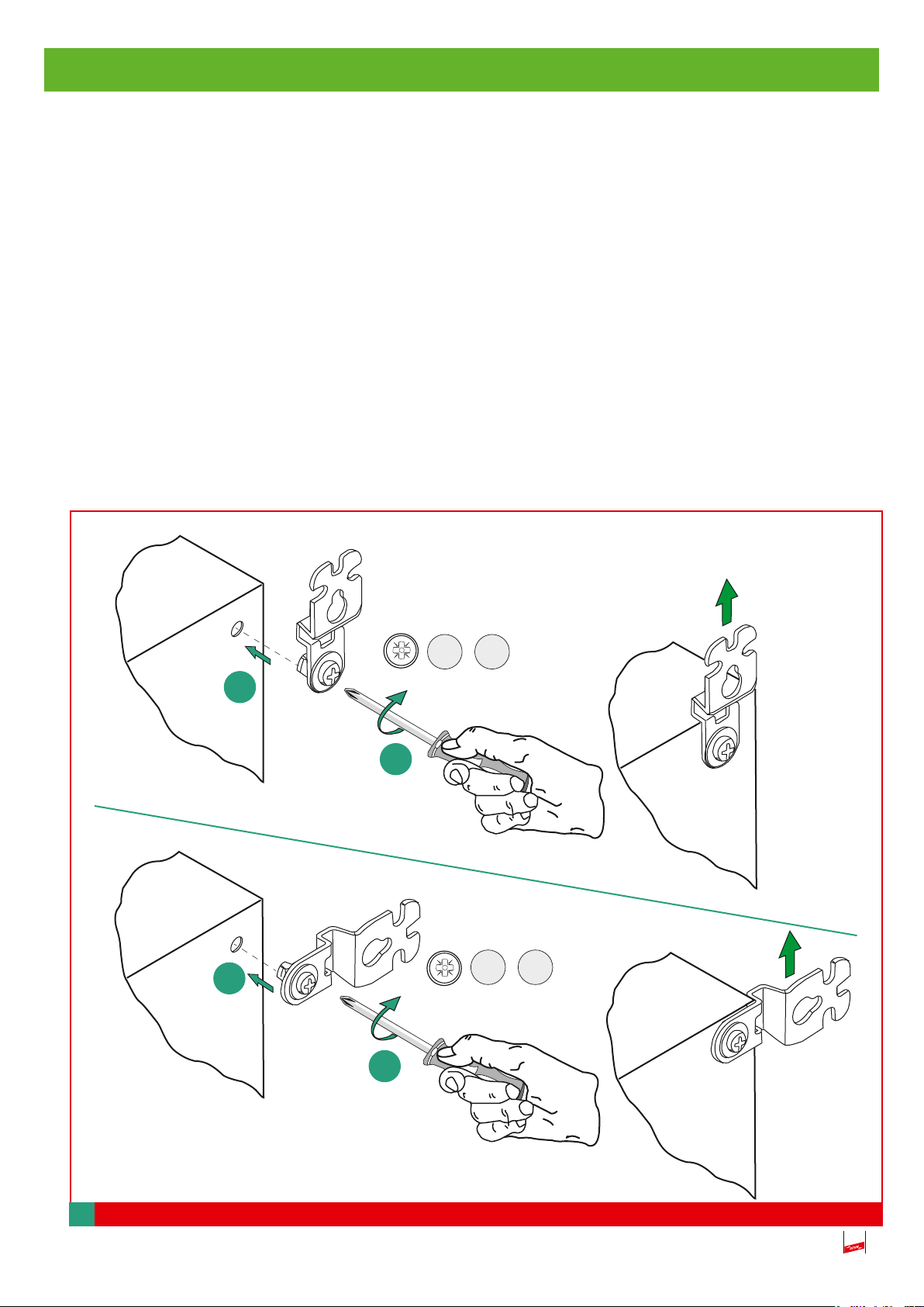
Eine mögliche Wandmontage kann mittels der im Lieferumfang enthaltenen Wandbefestigungslaschen erfolgen (siehe Fig. 3.1).
Vor der Montage müssen jedoch die vier Isolierstopfen (nicht abgebildet) aus der Gehäuserückwand
entfernt werden.
Danach wird die entsprechende Befestigungslasche an die jeweilige Bohrdurchführung
herangeführt/durchgeführt und festgeschraubt (Beachte hierzu Fig. 3.1).
Das Gehäuse des VCSD ist im Außenbereich durch entsprechende Maßnahmen (z.B. Outdoorgehäu-
se) vor Witterungseinflüssen zu schützen.
1
Gehäuserückwand
1
2
3 Nm
x 4
3 Nm
x 4
150 kg
330 Ib
150 kg
330 Ib
Gehäuserückwand
Fig. 3.1 Gehäuserückwand
2
7

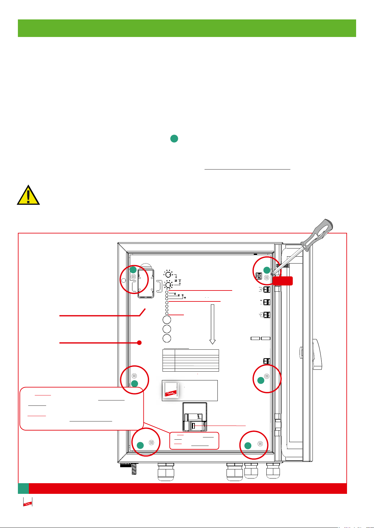
3.2 Demontage der Abdeckplatte
Für die weiteren Montage- und Anschlussarbeiten muss die Abdeckplatte abgenommen und die
Batterie aus dem Gehäuse entnommen werden (siehe Fig. 3.2)
Das Einsetzen der Brücke an den Klemmen „Digital IN“ ist für ein sicheres An- bzw. Abklemmen
der Hauptleitungen notwendig, da dadurch der VCSD abgeschaltet wird.
Zum Entnehmen der Batterie, zuerst O-Ring entfernen und dann die Batterie herauskippen (Beachte
hierzu Fig. 4.1.1, Seite 11).
Vor dem Herausnehmen müssen die sechs Befestigungsschrauben aufgeschraubt und entnom-
1
men werden (siehe Fig. 3.2).
Kondensatoren entladen!
Zum Entladen der Kondensatoren muss der Taster SVN 311 mindestens 10 Sekunden gedrückt
werden (siehe Fig. 3.2).
Die Abdeckplatte darf nur durch eine Elektrofachkraft entfernt werden!
Batteriefach
Abdeckplatte
Achtung: Nach Abklemmen des Pipeline- und PE-
Anschlusses die Kondensatoren für mindestens 10
Sekunden durch Drücken des Tasters SVN 311 entladen!
Attention: After disconnecting the pipeline and PE cable,
discharge the capacitors for at least 10 seconds by pushing
the button SVN 311!
1
V Einstellung Schwellenspannung U
Adjust threshold voltage Uth
3 ...50V
Fehlerzustand (Binär Code: Aus = 0, Rot =1,
s. Tabelle für Fehlerbeschreibung)
Failure Mode (binary Code: Off = 0, Red =1,
Batterie
Battery
9V
Fehlerzustände / Failure modes:
Binär Code Beschreibung/
Binary code Description
0 0 1 Dauerhafter Überstrom / Continuous overcurrent
0 1 0 Defekte Funkenstrecke / Faulty spark gap
0 1 1 Elektronikfehler / Electronic failure
1 0 0 Niedrige Batteriespannung / Low battery voltage
1 0 1 DC Spannungsfehler / DC Voltage vailure
1 1 0 Fehler Leistungselektronik / Faulty power electronics
Siehe Bedienungs- und Montageanleitung für eine detaillierte Beschreibung
See instruction manual for detailed description
1
1
see table for failure modes)
Selbsttest / Self-test
VCSD aus / VCSD off
Status
Fehlerstatus / failure mode
Rücksetzen Fehlerstatus
Reset failure mode
Start Selbsttest
Start self-test
Freigabe Schwellenspannung
Release threshold voltage
VCSD 40 IP65
923 401
IED = 40 A
Achtung: Nach Abklemmen des Pipeline- und PE-
Anschlusses die Kondensatoren für mindestens 10
Sekunden durch Drücken des Tasters SVN 311 entladen!
Attention: After disconnecting the pipeline and PE cable,
discharge the capacitors for at least 10 seconds by pushing
the button SVN 311!
th
Kabel-Clips
Externe
Spannungsversorgung
External power supply
(9-32 V DC, 2W)
Taster SVN 311
Digital IN
Analog OUT
(I
= 4 ...20 mA DC)
out
Digital OUT
cable clips
1
USB 2.0
1
0,6 Nm
1
Fig. 3.2 Abdeckplatte
8

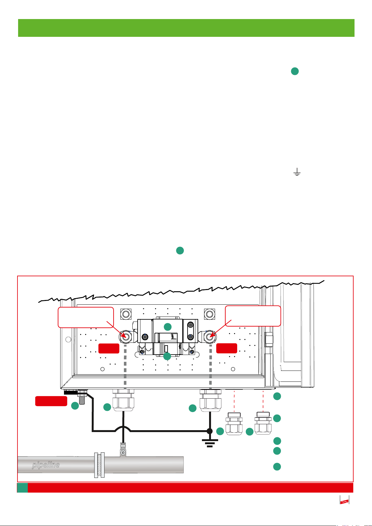
3.3 Anschluss der Hauptleitungen
Das Einführen der beiden Hauptleitungen (Pipeline u. PE) erfolgt über die beiden Kabelverschraubungen -M25- (Kabelaußendurchmesser Ø 11 ... 17 mm). Entsprechend sind die beiden
a
Anschlussleitungen wie folgt anzuschließen:
An- und Abklemmen soll nur bei eingesetzter Brücke „Digital IN“ erfolgen! (siehe auch Pkt. 6
VCSD aus, Seite 18).
Pipeline
Die Anschlussleitung von der Pipeline kommend, wird am Anschlusspunkt „1“ angeschlossen
(siehe Fig. 3.3).
Erder-Anschluss
Die Anschlussleitung vom Erder kommend, wird am Anschlusspunkt „2 ( )“ angeschlossen
(siehe Fig. 3.3).
Der Anschluss der Leitungen erfolgt am jeweiligen M10-Anschlussbolzen mittels einer M10Sechskantmutter. Hierfür wird ein Rohrkabelschuh-Anschluss empfohlen!
2
-Anschlussquerschnitt: min. 35 mm
Cu ... max. 50 mm2 Cu
Gehäuseerdung / Schutzpotential
Der Anschluss erfolgt über den M8-Gewindebolzen . Die Anschlussleitung muss einen Mindest-
d
querschnitt von 16 mm2 Cu aufweisen. Gleichermaßen wird hierbei ein Kabelschuh-Anschluss 16
mm2 empfohlen (siehe Fig. 3.3).
Angegebene Anzugsdrehmomente beachten!
Anschlusspunkt
“2“
17 Nm
b
b
Kabelverschraubung
a
-M25- Ø 11 ... 17 mm,
5 +/- 1 Nm
Kabelverschraubung
b
-M20- Ø 6 ... 12 mm,
5 +/- 0.5 Nm
c
Transient Unit
Gehäuseerdung
d
M8-Gewindebolzen
e
SVN311 Entladetaster
15±0,5 Nm
Pipeline
Anschlusspunkt
“1“
17 Nm
d
a
c
e
a
Fig. 3.3 Anschluss der Leitungen
Fig. 3.3 Connectionof the lines
9

Zubehör
Die beiden Kabelverschraubungen -M20- (Kabelaussendurchmesser Ø
Gehäuse lose beigepackt.
Sie sind für die Einführung von zwei Signalleitungen vorgesehen (siehe Fig. 3.3, Seite 9).
Anmerkung:
Im Bedarfsfall können die Signalleitungen (mittels Kabelverschraubungen -M20-) auch nachträglich ins Gehäuse eingeführt werden. Eine Demontage der Abdeckplatte ist hierbei nicht erforderlich.
Die Signalleitungen können direkt auf der Abdeckplatte mittels der Kabel-Clips befestigt werden
(siehe Fig. 3.2, Seite 8).
3.4 An- bzw. Abklemmen der Steuerleitungen
Das An- bzw. Abklemmen der Steuerleitungen Digital IN, Analog OUT, Digital OUT, ext. Spannungsversorgung erfolgt durch das Betätigen, Hineindrücken der Klemmenentriegelung (siehe Fig. 3.4).
b
6 ... 12 mm ) sind dem
Verbinden
size 00
1.
press
Fig. 3.4 An bzw. Abklemmen
2.
Lösen
1.
2.
size 00
press
10

4. Inbetriebnahme
Batterie
1.
4.1 Ablauf
Nach dem Anschluss der Hauptleitungen.
4.1.1 Batterie einlegen
Vor der Inbetriebnahme muss die Blockbatterie 9V
(Art.-Nr. 911 009) in das Batteriefach eingelegt
werden. Zum Sichern der Batterie muss der
3.
O-Ring wieder angebracht werden
(siehe Fig. 4.1.1).
Die Polarität ist zu beachten!
4.1.2 Externe Spannungsversorgung
Gegebenenfalls externe Spannungsversorgung
anlegen (siehe Pkt. 8, Seite 20).
4.1.3 Entfernen der Brücke am Eingang
Der VCSD wird in der Betriebsart „VCSD aus“
ausgeliefert. Durch Entfernen der Brücke vom
Eingang „Digital IN“ wird diese Betriebsart beendet und das Gerät ist betriebsbereit.
Anschließend kann eine externe Steuerleitung an
den Klemmen angeschlossen werden (
siehe Fig. 4.1.3).
2.
3.
+ Batterie -
Battery
9V
Fig. 4.1.1 Batteriefach
Brücke
Digital IN
Fig. 4.1.3
Entfernen der Brücke
Selbsttest/Self-test
VCSD aus / VCSD off
Externer
Anschluss
z.B.
Leitwarte
11

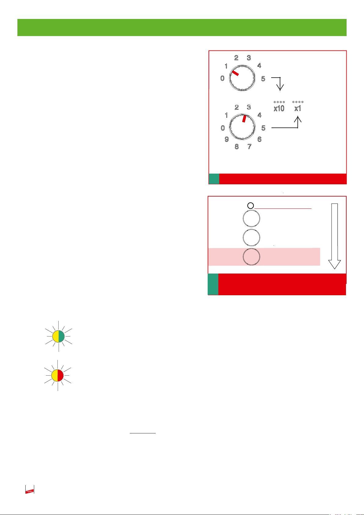
4.1.4 Einstellen der Ansprechschwelle
Bei der Inbetriebnahme muss die AC-Ansprechschwelle als Effektivwert entsprechend den Anforderungen
der Anwendung eingestellt werden (siehe Fig. 4.1.4a
und Fig. 4.1.4b).
Dazu muss sich das Gerät im Überwachungs- oder
Ableitbetrieb befinden. Ggf. ist das Gerät über die ext.
Spannungsversorgung zu betreiben.
Werksseitige Einstellung
Werksseitig ist die Ansprechschwelle mit 50 Volt
voreingestellt.
Vorgehensweise wie folgt beachten:
1
3
V
rms
Einstellung Schwellenspannung U
Adjust thresold voltage Uth
3 ...50 V
Fig. 4.1.4a Ansprechschwelle
th
1. Drücken und gedrückt halten der Taste „Freigabe
Schwellenspannung“.
2. Einstellen der benötigten Schwellenspannung über die
Drehkodierschalter.
3. Loslassen der Taste „Freigabe Schwellenspannung“.
4. Übernahme des neuen Schwellenwertes.
Es sind Werte von 3 ... 50V zulässig.
Bei Unterschreiten wird 3V, bei Überschreiten 50V
eingestellt und die Status LED blinkt wie folgt:
Status d.h. ungültige Schwelle während des
Überwachungsbetriebs
(abwechselnd gelb / grün)
Fehlerstatus / failure mode
Rücksetzen Fehlerstatus
Reset failure mode
Start Selbsttest
Start self-test
Taste
Freigabe Schwellenspannung
Release threshold voltage
Fig. 4.1.4b Freigabe
„Schwellenspannung“
button
Status d.h. ungültige Schwelle während des
Ableitbetriebs
(abwechselnd gelb / rot)
Es liegt ein Bedienfehler vor (siehe auch Fig. 4.2d, Seite 13).
Ein Ändern der Ansprechschwelle ohne Drücken der Taste „Freigabe Schwellenspannung“ führt ebenfalls
zu einer der zuvor beschriebenen LED-Anzeige „ungültige Schwelle“.
Dabei bleibt weiterhin die zuletzt korrekt eingestellte Schwelle aktiv und auch der 4 ... 20 mA-Ausgang ist
von diesem Bedienfehler unbeinflusst. Nur durch Drücken der Freigabe-Taste kann der „neue Wert“ übernommen werden, oder es muss der „alte Wert“ wieder eingestellt und mit der Freigabe-Taste bestätigt werden.
12

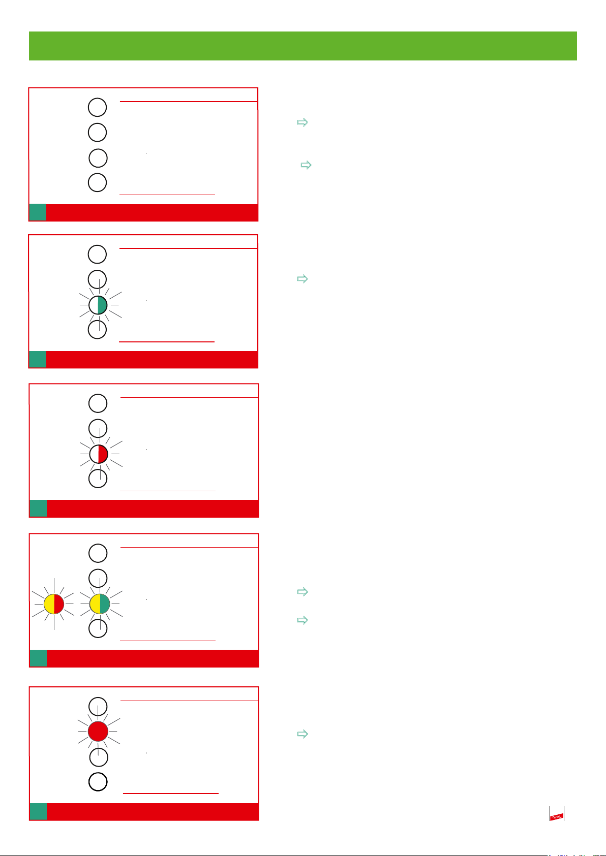
4.2 LED-Anzeige
Selbsttest / Self-test
VCSD aus / VCSD off
Keine LED leuchtet oder blinkt
Keine Beeinflussung vorhanden.
Gerät ist betriebsbereit.
Status
Fehlerstatus / failure
Fig. 4.2a „Status“ LED-Anzeige
Selbsttest / Self-test
VCSD aus / VCSD off
Status
Fehlerstatus / failure
Fig. 4.2b „Status“ LED-Anzeige
Selbsttest / Self-test
VCSD aus / VCSD off
„VCSD aus“ bzw. Fehlerstatus und tiefentladene
Batterie! (siehe Pkt. 1, Seite 3).
Status
Status LED grün blinkend.
Beeinflussung oder ext. Versorgungsspannung
vorhanden, aber keine Überschreitung der eingestellten Ansprechschwelle, Überwachungsbetrieb
aktiv.
Status
Status LED rot blinkend
Beeinflussung vorhanden, Ansprechschwelle über-
schritten, Ableitbetrieb aktiviert.
Status
Fehlerstatus / failure
Fig. 4.2c „Status“ LED-Anzeige
Selbsttest / Self-test
VCSD aus / VCSD off
Status
or
oder
Fig. 4.2d „Status“ LED-Anzeige
Fehlerstatus / failure
Selbsttest / Self-test
VCSD aus / VCSD off
Status
Status
Status LED grün/gelb oder rot/gelb blinkend,
Bedienfehler liegt vor!
ungültiger Wert eingestellt, Ansprechschwelle zu
hoch oder zu niedrig
Der geänderte Wert der Ansprechschwelle wurde
nicht freigegeben
grün/gelb während des Überwachungsbetriebs
rot/gelb während des Ableitbetriebs.
VCSD
„VCSD aus“ LED rot leuchtend.
Abschaltbetrieb, Manuell- Aus, die Überwachung
der festen Schwelle von 50 V erfolgt nur bei anliegender ext. Spannungsversorgung (siehe auch Pkt.
6, Seite 18).
Fehlerstatus / failure
Fig. 4.2e „Status“ LED-Anzeige
13

Selbsttest / Self-test
Selbsttest, LED gelb blinkend (abwechseld zu
Status LED)
VCSD aus / VCSD off
Status
Fehlerstatus / failure
Fig. 4.2f„Selbsttest“ LED-Anzeige
Selbsttest / Self-test
VCSD aus / VCSD off
Status
Fehlerstatus / failure
Fig. 4.2g „Selbsttest“ LED-Anzeige
Selbsttest / Self-test
VCSD aus / VCSD off
Taste „Selbsttest“ wurde gedrückt!
Selbsttest läuft; Externe Spannung liegt an.
Selbsttest LED 5 Sekunden grün leuchtend.
Selbsttest OK Gerät ist in Ordnung!
Selbsttest LED 5 Sekunden gelb leuchtend.
Selbsttest abgebrochen, Pipelinepotential liegt noch
an, Gerät zuerst abklemmen.
Status
Fehlerstatus / failure
Fig. 4.2h„Selbsttest“ LED-Anzeige
Selbsttest / Self-test
VCSD aus / VCSD off
Status
Fehlerstatus / failure
Fig. 4.2i „Selbsttest“ LED-Anzeige
Selbsttest / Self-test
VCSD aus / VCSD off
Status
Fehlerstatus / failure
Fig. 4.2j „Fail-safe“ LED-Anzeige
Selbsttest LED 5 Sekunden rot leuchtend.
Selbsttest nicht OK Gerät ist defekt!
Es wechselt automatisch in den Fehlerstatus.
Der entsprechende Fehlerzustand wird angezeigt
(siehe Tabelle 1, Seite 23).
Fehlerstatus LED und Fehlerzustand LED‘s
rot leuchtend
Externes (kundenseitiges) Fail-Safe-Relais kann über
den Schaltausgang des Digital OUT angesteuert
werden.
Abschaltbetrieb Fehler, es erfolgt keine Überwa-
chung der Schwellenspannung.
Eingriff vor Ort notwendig!
14

4.3 Fehlerstatus
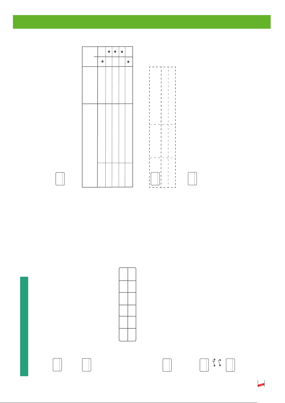
4.3.1 Fehlerzustände
Mögliche Fehlerzustände werden binär kodiert (Dualsystem 0/1) und entsprechend über die drei
Fehlerzustand-LED‘s
- LED rot leuchtend steht für Binärcode 1
- LED nicht leuchtend steht für Binärcode 0
angezeigt bzw. zugeordnet (siehe Fig. 4.3.1).
Die Fehlerzustand-LED‘s sind im Gehäuse bzw. an der Abdeckplatte untereinander angeordnet.
Die binäre Auswertung erfolgt über die rechts der LED‘s zugeordneten Platzhalter (siehe Fig. 4.3.1).
Funktionsbeispiel:
Die oberste LED leuchtet nicht steht für Binärcode 0
Die mittlere LED leuchtet nicht steht für Binärcode 0
Die unterste LED leuchtet rot steht für Binärcode 1
Es ergibt sich somit ein Binärcode von: 0 0 1
Gemäß der Binärcode-Tabelle liegt der Fehlerzustand „Dauerhafter Überstrom“ vor (siehe Fig. 4.3.1).
Diagnose / Fehleranalyse
Eine genauere Analyse der jeweiligen Fehlerzustände und deren möglichen Abhilfemaßnahmen können
aus der Tabelle 1 „Diagnose / Fehleranalyse“auf der Seite 23 entnommen werden.
Hinweis:
Die Fehlerzustand-LED‘s werden ausschließlich über die 9 Volt-Blockbatterie oder ext. Versorgung gespeist! Entsprechend sollte eine regelmäßige Überprüfung bzw. Wartung durchgeeführt werden! D.h. Überprüfung des Digital OUT auf Kontakt offen wenn am Gerät keine LED
leuchtet, um eine vollständige Entladung der Batterie auszuschließen!
(Kontakt geschlossen ⇒ Gerät im Fehlerstatus und Batterie leer, wenn keine LED leuchtet!).
Fehlerzustand (Binärcode: Aus = 0, Rot =1,
s. Tabelle für Fehlerbeschreibung)
Failure Mode (binary Code: Off = 0, Red =1,
see table for failure modes)
3 x LED
3 x LED
Fehlerzus
s. Tab
Failure M
see ta
Fehlerzustände / Failu
Binär Code Besch
Binary code Descri
Fehlerzustände / Failure modes:
Binär Code Beschreibung/
Binary code Description
0 0 1 Dauerhafter Überstrom / Continuous overcurrent
0 1 0 Defekte Funkenstrecke / Faulty spark gap
0 1 1 Elektronikfehler / Electronic failure
1 0 0 Niedrige Batteriespannung / Low battery voltage
1 0 1 DC Spannungsfehler / DC Voltage failure
1 1 0 Fehler Leistungselektronik / Faulty power electronics
0 0 1 Dauerh
Funktionsbeispiel
Fig. 4.3.1 Fehlerzustände
15
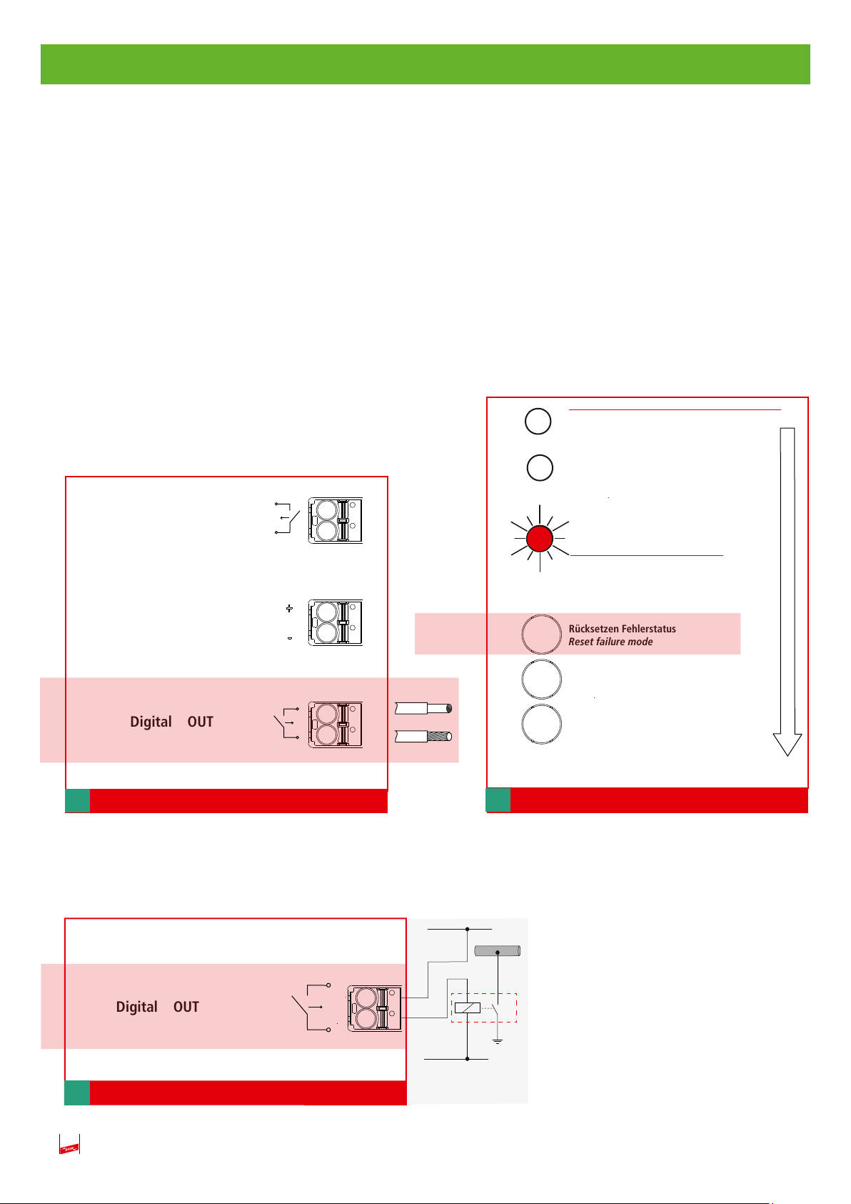
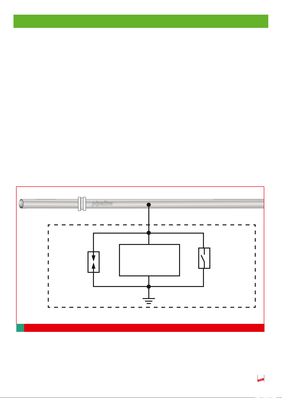
4.3.2 Fehlerstatus-Relais
- Bei Auftreten eines Fehlers wird automatisch der Fehlerstatus aktiviert,d.h. das Gerät verhält
sich hochohmig und es findet keine Überwachung des Schwellenwertes mehr statt.
- Ein externes Fehlerstatus-Relais (z.B. Schaltschütz) kann zur Erhaltung des Personenschutzes
übergeordnet angeschlossen werden (siehe Fig. 4.3.2c).
- Nach einer Fehleranalyse (siehe Tabelle 1, Seite 23). und ggf. Beseitigung des Fehlers kann der
Fehlerstatus durch Drücken der Taste „Rücksetzen Fehlerstatus“ wieder beendet werden
(siehe Fig. 4.3.2b).
- Das Gerät geht wieder in seinen Normalbetrieb über, das externe Fehlerstatus-Relais wird
deaktiviert.
Selbsttest / Self-test
VCSD aus / VCSD off
Digital IN
Analog OUT
(I
= 4 ...20 mA DC)
out
Digital OUT
Taste
max. 2.5 mm²
Fig. 4.3.2a
Externes Fehlerstatus-Relais, Anschlussschema
Ein ext. Fehlerstatus-Relais wird angesteuert sobald ein
Fehlerzustand vorliegt.
Status
Fehlerstatus
Rücksetzen Fehlerstatus
Reset failure mode
Start Selbsttest
Start self-test
Freigabe Schwellenspannung
Release threshold voltage
Fig. 4.3.2b
16
Digital OUT
Fig. 4.3.2c Fehlerstatus- Relais
Pipeline
externes
Fehlerstatus-Relais
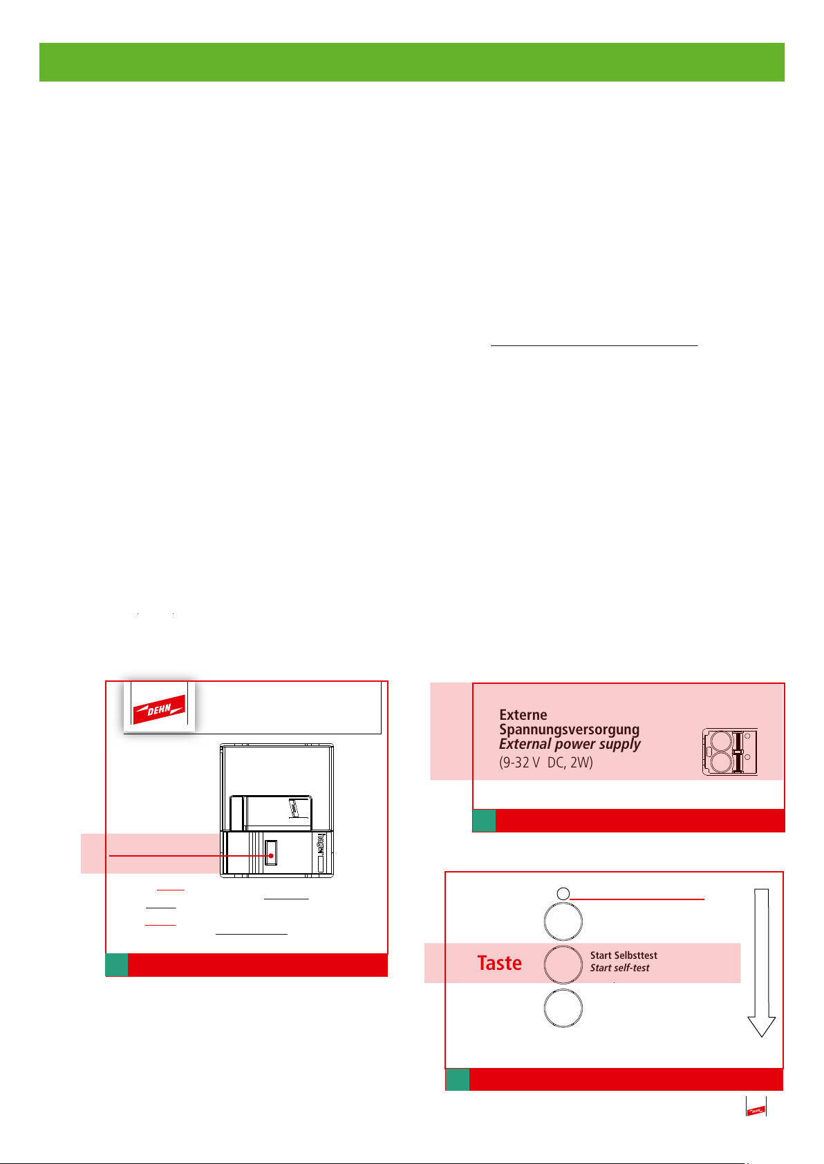
5. Selbsttest
Der Selbsttest kann nur nach dem Entfernen bzw. Abklemmen der beiden Hauptleitungen (Pipeline
u. PE) und dem Entladen der Kondensatoren erfolgen. Dazu wie folgt vorgehen:
5.1 Abklemmen (siehe auch Pkt. 3.2, Seite 8 und Pkt. 3.3, Seite 9).
Nach der Demontage der Abdeckplatte, wie unter Pkt. 3.2, Seite 8 beschrieben müssen zum Abklemmen die beiden M10-Sechskantmutter vom Anschlusspunkt „1“ und „2“abgeschraubt werden.
Danach können die beiden Leitungen vom jeweiligen M10-Anschlussbolzen abgenommen werden
(siehe hierzu Fig. 3.3, Seite 9).
5.2 Entladen
Zum Entladen der Kondensatoren muss der Taster SVN 311 mindestens 10 Sekunden gedrückt
werden (siehe Fig. 5.2).
5.3 Externe Spannungsversorgung
- Anlegen der externen Versorgungsspannung (9…32V, DC)
- Entfernen der Brücke „VCSD aus“ am Digital IN (die Status LED blinkt grün)
- Selbsttest mit der Taste „Start Selftest“ starten, siehe Fig. 5.3b
- Während des Selbstest blinkt die Selbsttest LED gelb, abwechseld zur grünen LED Status
Umfang des Selbstests:
a) Test der Leistungselektronik auf Kurzschluss
b) Abfrage der Steuerspannung (Test der Elektronik)
- Nach dem Selbsttest erfolgt die Statusanzeige über den Zustand des Gerätes für 5 Sekunden
(grün, gelb oder rot) siehe Pkt. 4.2g/h/i, Seite 14
923 401
IED = 40 A
Taster SVN 311
Drücken mind.10 Sek.
Achtung: Nach Abklemmen des Pipeline- und PE-
Anschlusses die Kondensatoren für mindestens 10
Sekunden durch Drücken des Tasters SVN 311 entladen!
Attention: After disconnecting the pipeline and PE cable,
discharge the capacitors for at least 10 seconds by pushing
Fig. 5.2 Entladen
the button SVN 311!
Externe
Spannungsversorgung
External power supply
(9-32 V DC, 2W)
+ (-)
- (+)
Fig. 5.3a Anschließen 9- 32 V
Fehlerstatus / failure mode
Rücksetzen Fehlerstatus
Reset failure mode
Taste
Start Selbsttest
Start self-test
Freigabe Schwellenspannung
Release threshold voltage
Fig. 5.3b Start Selbsttest
17

6. VCSD aus
Bei der intensiven Fehlerortung (IFO) sind von KKS-Fachkräften umfangreiche messtechnische Untersuchungen notwendig, damit Umhüllungsfehler (sog. Fehlstellen) an Pipelines lokalisiert werden
können. Hierbei sollte der VCSD hochohmig sein, damit die Rohrleitungskapazitäten durch den
VCSD nicht verfälscht werden und somit die „Taktung“der Messung beinflussen. Die Aktivierung des
Manuell-Aus erfolgt über den digitalen Eingang „Digital IN“.
Eingang Digital IN:
Dient der gezielten Abschaltung des Gerätes per Fernzugriff, um eine mögliche Beeinflussung,
z.B. während einer intensiven Fehlerortung (IFO) durch KKS-Fachkräfte auszuschließen oder um
ein sicheres An- und Abklemmen zu ermöglichen (Brücke “VCSD aus“, siehe Fig.6c)
Ist nicht galvanisch getrennt, deshalb muss hier ein potentialfreier Schließerkontakt
(siehe Fig. 6a) zur Aktivierung verwendet werden (Schaltdaten: 9 V, 1 mA, max. 100 Ω)
Kontakt geschlossen VCSD-Aus
- ohne externe Spannungsversorgung: Manuell-Aus
- mit externer Spannungsversorgung: Manuell-Aus mit Überwachung einer
festen Schwelle von 50 V
Kontakt offen Standardbetrieb
Die Aktivierung kann aus allen Standardbetriebsarten heraus (betriebsbereit, Überwachungs- und
Ableitbetrieb) erfolgen und wird über die LED vor Ort angezeigt (siehe Fig. 6 b).
Der 4 ... 20 mA-Ausgang verbleibt fest bei 4.0 mA, wenn das Gerät extern versorgt wird (siehe
auch die Prinzipdarstellung „Betriebsmodi“ Seite 24).
Während des Manuell-Aus erfolgt die Überwachung einer festen Ansprechschwelle von 50 V nur
bei anliegender externen Spannungsversorgung!
Digital IN
Anschlussquerschnitt: max 2,5mm
2
Externer
Anschluss
z.B.
Leitwarte
Fig. 6a Externer Relaiskontakt
Brücke
Selbsttest / Self-test
Fig. 6b Manuell-Aus
18
VCSD aus / VCSD off
Status
Fehlerstatus / failure m
Digital IN
Fig. 6c Brücke „VCSD aus“
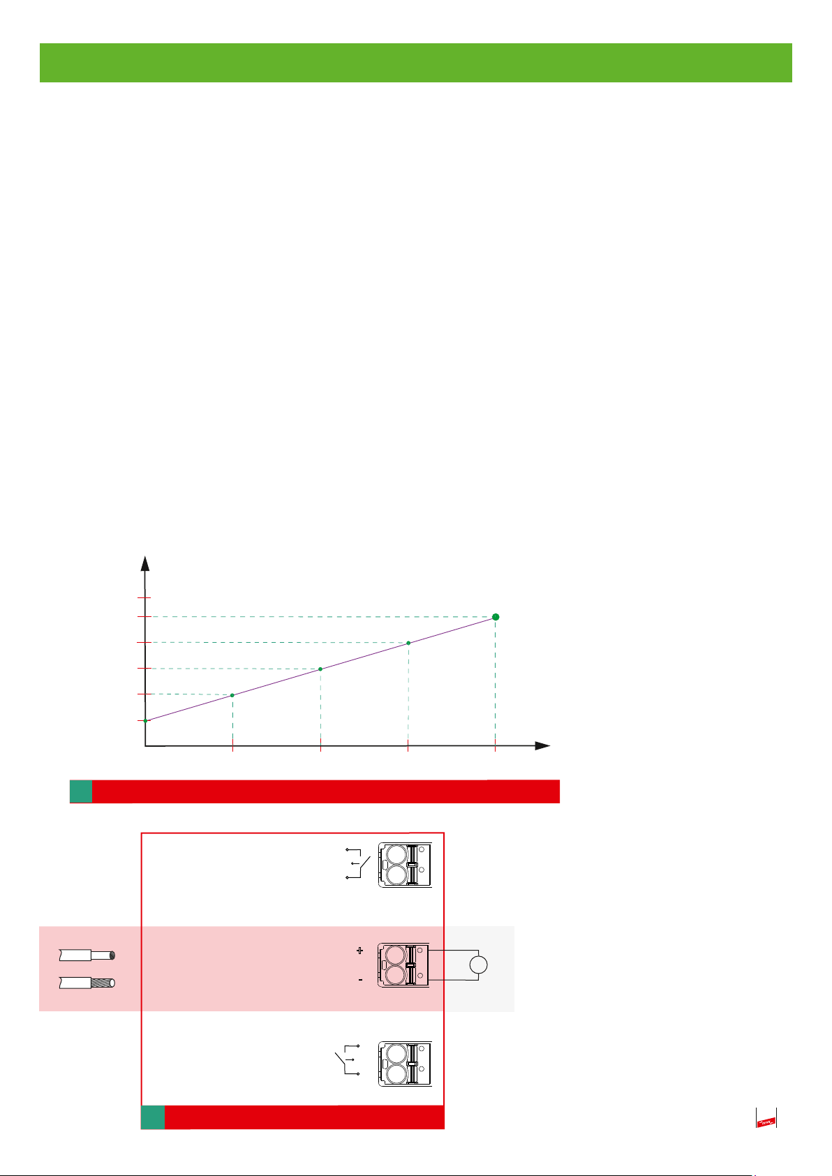
7. Analog OUT (Monitoring Ableitstrom)
4-20 mA-Stromausgang (siehe auch Fig. 7 und Diagramm 7):
Benötigt die ext. Spannungsversorgung zum Betrieb.
Zulässiger Bereich: 9 ... 32 V DC / 150 ...50 mA
Ist galvanisch getrennt
Das DC 4 ... 20 mA- Ausgangssignal entspricht einem aktuellen Ableitstrom von 0 ... 40 A
eff
, d.h.
0,4 mA / 1A.
Zur Fernsignalisierung eines Fehlerzustands am Gerät, der einen Bedienereingriff vor Ort erfordert,
wird ein Alarm-Wert von 22,8 mA übertragen.
< 4 mA Drahtbruch, oder keine ext. Spannungsversorgung
4,0 mA Überwachungsbetrieb oder Abschaltbetrieb- VCSD
4 - 20 mA Ableitbetrieb mit 0 ... 40 A, Ableitstrom
22,8 mA Fehlersignalisierung, Vor-Ort-Eingriff notwendig!
[mA DC]
22,8
20
16
12
max. 2.5 mm²
8
4
0
Diagramm 7
Digital IN
Analog OUT
= 4 ...20 mA DC)
(I
out
Digital OUT
10
20
30
[A
40
A
eff
]
Fig. 7
19

8. Externe Versorungsspannung (9 ... 32V, DC)
(siehe auch Fig. 8)
Dient zur dauerhaften, von einer Beeinflussung unabhängigen Versorgung des Gerätes
Zulässiger Bereich: 9-32 V
/ 150 ...50 mA
DC
Ist galvanisch getrennt
Ist zur Ausführung eines Selbsttest zwingend erforderlich
Ersetzt nicht die Batterie
Versorgt auch den 4 ... 20 mA-Ausgang
max. 2.5 mm²
Externe
Spannungsversorgung/
External power supply
(9 ... 32 V DC, 2W)
Fig. 8
Fig. 8
+ (-)
- (+)
9. USB-Schnittstelle (nur für Hersteller zugänglich)
In Form einer USB 2.0 Typ B Buchse
Ist galvanisch getrennt
z.B. Netzteil
+
Typ. PSU DC24 30W
Art.-Nr. 910499
20
Das Gerät und die Batterien dürfen nicht über den Hausmüll entsorgt werden!
Weiterführende Informationen entnehmen Sie unserer Homepage:
www.dehn.de
10. Technische Daten
Typ VCSD 40 IP65
Type VCSD 40 IP65
Art.-Nr.
Ableitstrom transient (10/350 µs)
Ableitstrom transient (8/20 µs)
Ableitstrom temporär (16,7 Hz, 50 Hz, 60 Hz)
Ableitstrom temporär (16,7 Hz, 50 Hz, 60 Hz)
Ableitstrom stationär (16,7 Hz, 50 Hz, 60 Hz)
Begrenzungsspannung transient (bis 1 ms)
Begrenzungsspannung temporär (ACrms) (1 ... 20 ms)
Begrenzungsspannung temporär (ACrms) (20 ... 100 ms)
Begrenzungsspannung temporär (ACrms) (100 ... 200 ms)
Begrenzungsspannung stationär (ACrms) (> 200 ms)
Frequenzbereich AC
Max. zulässige DC-Spannung im Ableitbetrieb
Max. Leckstrom im Nichtableitbetrieb bei Tamb = 20 °C
Spannungsversorung (intern)
Stromaufnahme (intern, typisch bei 1Ω Erdungswiderstand)
Spannungsversorung (extern, optional)
923 401
100 kA
100 kA
1,1 kA
40 A
(bis 200 ms) *1)
eff
500 A
eff
(bis 1s)
eff
(dauerhaft) *2)
≤ 1,25kV
≤ 940V (1 kV nach AfK 3)
≤ 660V (1 kV nach AfK 3)
≤ 400V (1 kV nach AfK 3)
max. 50 V (einstellbar 3 ... 50 V)
16,7 Hz, 50 Hz, 60 Hz
±7VDC
max. 500 µA
durch Fremdspannung; 9 V Batterie integriert
< 1A (U
< 2A (U
< 0,5A (U
< 5 V)
ac
5 - 6 V)
ac
> 6 V)
ac
9 ... 32 V DC, min. 0,5 A
Betriebstemperaturbereich (TU)
Anschlüsse 1, 2
Schraubanschlüsse M10, Leiterquerschnitt 35 ... 50 mm²
Anschluss PE
Gehäusewerkstoff
Stahlblech lackiert, RAL 7035, Sichttür mit Sicherheitsglas
Schutzart
Digitaler Ausgang / Kontaktform
Schaltleistung AC
Schaltleistung DC
max. 220 V / max. 2 A / max. 60 W
Digitaler Eingang / Kontaktform
Kontaktdaten
Anschlussquerschnitt Signalleitungen
max. 2,5 mm
Abmessungen
Gewicht
VPE
*1)
Derating abhängig vom „Vorstrom“ (stationärer Ableitstrom) und der Umgebungstemperatur
*2)
Derating abhängig von der Umgebungstemperatur
-40 °C ... +80 °C
M8 (außenliegend)
IP 65
Schließer
max. 230 V / max. 0,6 A
Schließer
max. 9 V / 1 mA / 100 Ohm
2
ein- / feindrähtig
400 x 300 x 150 mm
12,1kg
1Stk.
21

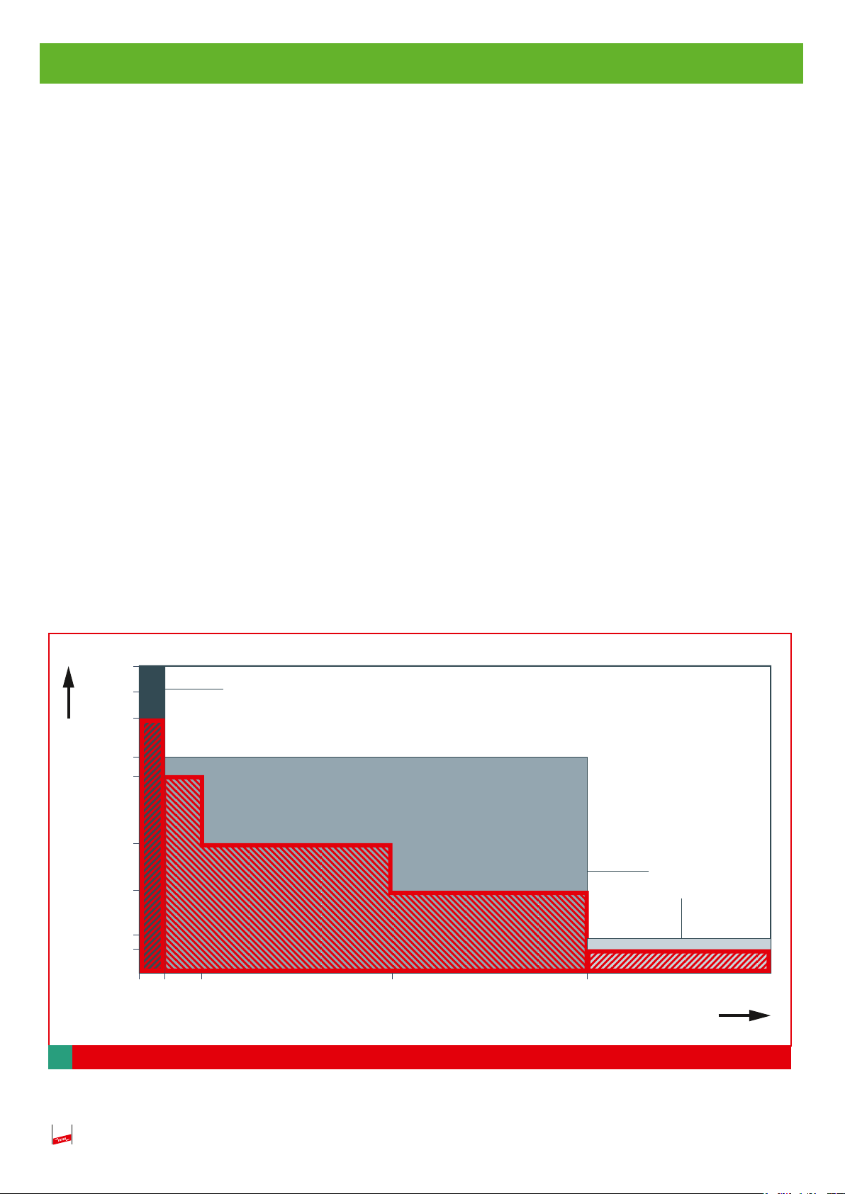
11. Derating stationärer Ableitstrom
in °C
amb
T
22
rms
eff
Derating für den stationären Ableitstrom in Abhängigkeit der
Umgebungstemperatur im Stahlgehäuse
in A
in A
stat
stat
I
I
12. Diagnose / Fehleranalyse
Binary code
0 0 1
*1)
0 1 0
0 1 1
1 0 0
1 0 1
*2)
Beschreibung
zulässiger Stationärer
Ableitstrom überschritten
Temperaturüberwachung hat angesprochen
Defekte Funkenstrecke /
Faulty spark gap
Elektronikfehler /
Electronic failure
Niedrige Batteriespannung / Low battery
voltage
Spannungsfehler /
Voltage failure
Ursache
I
siehe Pkt. 11, Seite 22
stat
thermische Überlastung
des Gerätes
Funkenstrecke überlastet
Steuerelektronik defekt
Batterie leer
Kondensatorspannung +/- 7V
DC überschritten
Abhilfe
Reset Taste betätigen, bei erneutem Auftreten
techn. Anforderungen mit den Leistungsdaten
des VCSD vergleichen (Derating in Abhängikeit
der Umgebungstemperatur beachten!),
Kontaktieren sie den
Service +49-9181-906-0
Schutzmodul tauschen (Art.-Nr. 961 010) und
danach Reset Taste betätigen
Reset Taste betätigen, bei erneutem Auftreten
kontaktieren sie den Service +49-9181-906-0
Batterie austauschen (Art.-Nr. 767 712) und
danach Reset-Taste betätigen
DC Potential auf Pipeline zu hoch, ggfs. KKS
Einstellung überprüfen und ggf.
Reset-Taste betätigen
Kontaktieren sie den Service +49-9181-906-0
1 1 0
Fehler Leistungselektronik /
Faulty power electronics
Selbsttestfehler:
Leistungselektronik defekt
(Anzeige nach Betätigung der
Selbsttest-Taste; solange eine
externe Versorgungsspannung
angeschlossen ist, leuchtet der
Fehlerstatus "1 1 0" zusammen mit der Selbsttest -LED
(rot), nach Abklemmen der
externen Versorgungsspannung erlischt die Selbsttest
-LED und es leuchtet nur noch
der Fehlerstatus "1 1 0"
Tabelle 1
*1) und *2)
Kurzzeitiges Auftreten dieser Fehlerzustände wird als unkritisch betrachtet, deshalb kann das Gerät
diese Fehlerzustände bis zu 3 x selbstständig zurücksetzen!
D.h. ein automatischer „Neustart“ erfolgt nach:
- *1) einer Stunde
- *2) zwei Minuten
Erst beim 4. Auftreten des selben Fehlers, ohne dass zwischenzeitlich ein automatischer Neustart
erfolgreich war (d.h. Neustart mit noch bzw. wieder anliegendem Fehler), erfolgt eine endgültige
Abschaltung des Gerätes, die nur durch Betätigung der Reset-Taste vor Ort wieder rückgängig
gemacht werden kann.
23
off
check
Selbsttest
VCSD aus /
Status
Fehlerstatus
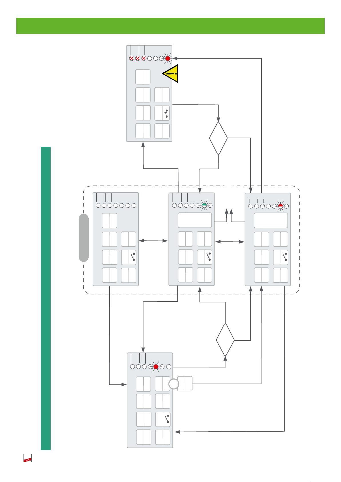
Standardbetrieb
off
check
Uth
check
on
VCSD
Selbsttest
VCSD aus /
Status
PU
D OUT
th
U
PS
Abschaltbetrieb Fehler
Fehlerstatus
off
off
off
VCSD
off
off
PU
D OUT
4-20 mA
Power
on
off
22,8
Fehlerstatus
check
Uth
VCSD
ResetorRestart
nach 1h bzw.
2 min
< Uth
Status
Selbstest
VCSD aus /
Fehlerstatus
cap
temp
-U
-I
-Batterie
off
PU
check
on
D OUT
?
AC
U
Bedienfehler
th
> U
> Uth
check
-Batterie
-U
on
Uth
on
VCSD
Fehlerstatus
Selbsttest
VCSD aus /
cap
max
dauer-Itemp
-T
-I
PU
D OUT
Status
gate
-V
Fehlerstatus
on
PS
betriebsbereit
Digital IN
Standby
off
4-20 mA
geschlossen
on
Überwachungsbetrieb
4,0
4-20 mA
< Uth
PS
on
Ableitbetrieb
4-20 mA
4-20
Digital IN
geschlossen
PS
?
AC
Digital IN
geschlossen
U
> Uth
Selbsttest
off
check
th
U
50 V
off
VCSD
Prinzipdarstellung Betriebsmodi
PS
off
Abschaltbetrieb manuell
VCSD aus /
Status
ext
U
PU
D OUT
4-20 mA
Fehlerstatus
on
off
4,0
Digital IN
geöffnet
AC
+
U
>50 V
24
Überwachung folgender Parameter
check
- off ...Keine Überwachung
nein
Fehler
ja
Kritischer
Überwachungs-Parameter ok, wenn..
DC
> 6,0 V
batt
Batterie Batteriespannung U
DV
< ± 7,0 V
cap
DC-Potential der Pipeline U
cap
U
eff
< 40 A
dauer
zul. Dauerstrom I
dauer
I
< 85°C
max
Ansteuerung Power Unit (PU) active
zul. Temperatur T
gate
max
V
T
VCSD am Pipeline
Eingang
- off hochohmig wird nicht beeinflusst
Wichtiger Hinweis:
VCSD
Unkritische Fehler kann das System selbsttätig zurücksetzen!
- on niederohmig wird beeinflusst
ext
U
Externe Spannungsversorgung 9 - 32 V
- on ...liegt am VCSD an.
Bedeutung der i-con‘s
PU
Halbleiterschalter der Power-Unit (PU)
- on ...eingeschaltet
4-20 mA
- off ...ausgeschaltet
Analoge Stromschnittstelle 4 - 20 mA
- off ...Schnittstelle aus, wegen fehlender Spannungsversorgung
- < 4 mA ...Drahtbruch oder externe Spannungsversorgung fehlt
- 4.0 mA ...ein, aber kein Ableitbetrieb
mA 4 8 12 16 20
A 0 10 20 30 40
- 4 - 20 mA ...Ableitbetrieb, Ableitstrom 0 - 40 A entspricht 4 - 20 mA
- 22.8 mA ...Abschaltbetrieb Fehler, Fehlerstatus liegt vor
PS
Bei kritischen Fehlern, Eingriff vor Ort notwendig! (siehe Pkt. 12)
Internes Netzteil, zur Versorgung aus dem AC- Pipeline-Potential
AC
U
> 1,5 V
AC
- off ...ausgeschaltet
- Standby ...bereit, wartet auf Eingangsspannung
- on ...in Betrieb, durch U
D OUT
(Digital OUT) Potentialfreier Kontakt zur Ausgabe einer Sammelstörung.
Die Ausgabe (Kontakt geschlossen) erfolgt nur bei Fehlerstatus
)
th
U
th
U
- off ...es findet keine Überwachung der Ansprechschwelle statt
- check ...die Ansprechschwelle wird überwacht
- 50 ...ausgesetzt, es wird eine Schwelle von 50 V überwacht, wenn
- ...geschlossen
- ...offen
Aktuelle Ansprechschwelle (
eine ext. Spannungsversorgung anliegt.
- on ...die Ansprechschwelle wurde übeschritten
25

-Beeinflussung wechselt das Gerät
AC
th
U
Begriffserläuterungen:
Standardbetrieb
Umfasst die Betriebsmodi
- betriebsbereit, Überwachungs- und Ableitbetrieb. Das Gerät ist betriebs -bzw. funktionsbereit.
26
Power
Durch Anlegen einer
durch eine vorhandene
AC
- externen Versorgungsspannung von 9 -32 VDCoder
von betriebsbereit in den Überwachungsbetrieb.
- ab einer Klemmenspannung > 1,5 V
) überschritten wird in den Ableitbetrieb geschaltet.
th
(U
Dieser wird erst wieder verlassen, wenn der Mindestableitstrom unterschritten ist.
Bedienfehler
Liegt vor, wenn:
- die Ansprechschwelle ohne Freigabe (Taste) geändert wurde. Es bleibt die zuletzt freigegebene Ansprechschwelle aktiv .
Schwellenspannung
Wird die aktuelle Ansprechschwellenspannung
oder
während Überwachungsbetrieb
während Ableitbetrieb
D OUT
4-20 mA
check
VCSD
bis eine Freigabe / Korrektur erfolgt.
>>>> Bleiben unverändert entsprechend der Betriebsart
- eine ungültige Ansprechschwelle freigegeben wird. Es wird automatisch 3 V (bei Unterschreitung) bzw. 50 V (bei Überschreitung) eingestellt.
PS PU
In beiden Fällen erfolgt eine Anzeige am Gerät,
Digital IN geschlossen
Durch Schließen des digitalen Eingangs wird das Gerät gezielt in den Abschaltbetrieb gebracht (auch bei betriebsbereit), bis der Kontakt wieder geöffnet wird.
Das Gerät wechselt dabei direkt in den aktuell benötigten Betriebsmode zurück.
Fehlerstatus
Die Parameter-Überwachung erkennt einen kritischen Fehler und bringt das Gerät automatisch in einen sicheren Zustand. Die Anzeige des Fehhlerzustands erfolgt im Detail
am Gerät (LED X X X) und allgemein über die 4-20 mA-Stromschnittstelle (22,8 mA). Bei unkritischen Fehlern erfolgt bis zu 3 mal nach jeweils 1h bzw. 2 min ein automatischer
Neustart. Nach erneutem Fehler wird ein kritischer Fehler generiert und das Gerät verbleibt im Abschschaltbetrieb Fehler.
Ein Bedienereingriff vor Ort, d.h. die Betätigung der Taste „Rücksetzen Fehlerstatus“ ist notwendig (siehe auch Pkt. 4.3.2, Seite 16)!

Ersatzteilliste / Zubehör
Blockbatterie Typ. 9V Lithium-Manganese Dioxide (Li-Mn O
Netzteil Typ. PSU DC24 30W
Art.-Nr. 910499
Überspannungsschutz
- Digital IN: Typ. BXT BAS Art.-Nr. 920 300 und Typ. BXT ML4 B 180 Art.-Nr. 920 310
- Digital OUT: Typ. BXT BAS Art.-Nr. 920 300 und Typ. BXT ML4 B 180 Art.-Nr. 920 310
- Analog OUT: Typ. BXT BAS Art.-Nr. 920 300 und Typ. BXT ML4 BE 24 Art.-Nr. 920 324
) Battery
2
27

Überspannungsschutz DEHN + SÖHNE Hans-Dehn-Str. 1 Tel. +49 9181 906-0
Blitzschutz/Erdung GmbH + Co.KG. Postfach 1640 www.dehn.de
Arbeitsschutz 92306 Neumarkt
DEHN schützt®. Germany

Surge protection
Instruction for use / installation instructions
Voltage-controlled smart decoupling device
VCSD 40 IP65
GB
Publication No. 1880/
Update 09.17 Mat-No. 3006917
www.dehn-international.com
© Copyright 2017 DEHN + SÖHNE

Contents
1. Safety notes..................................................................................3
2. Description ...................................................................................4
2.1 Application. ............................................................................................5
2.2 Functional description.............................................................................6
3. Installation and connection..........................................................7
3.1 Wall mounting ........................................................................................7
3.2
3.3
3.4
4.
4.1
4.1.1
4.1.2
4.1.3
4.1.4
4.2
4.3
4.3.1
4.3.2
Removal of the cover plate
Connection of the main lines
Connection / disconnection of the control lines
Commissioning
Procedure
Inserting the battery
External power supply
Removal of the “VCSD off” jumper
Setting the response threshold
LED indications
Failure mode
Fault states
Failure mode relay
...............................................................................................11
.............................................................................................15
..............................................................................11
................................................................................11
........................................................................................13
...........................................................................................15
...................................................................................16
.......................................................................8
....................................................................9
..............................................................................11
...........................................................11
.................................................................12
.........................................10
5. Self-test ........................................................................................17
5.1 Disconnection.........................................................................................17
5.2 Discharge ...............................................................................................17
5.3
6. VCSD off .......................................................................................18
7. Analog OUT...................................................................................19
8.
9. USB interface................................................................................20
10. Technical data...............................................................................21
11.
12.
13.
2
External power supply
External power supply
Derating for the long-duration discharge current
Diagnosis / fault analysis
Schematic diagram of the operating modes
..............................................................................17
...................................................................20
.........................22
...............................................................23
..................................24

IEC 60417-6182:
Installation,
electrotechnical expertise
1. Safety notes
The VCSD 40 IP65 voltage-controlled smart decoupling device
may only be installed by an electrically skilled person.
The national rules and safety regulations must be observed (in Germany, DIN VDE 0105-100, AfK recommendations No. 3, No. 5 and No. 11).
Prior to installation, the VCSD 40 IP65 smart decoupling device must be checked for signs of external
damage. If damage or any other defect is found, the VCSD 40 IP65 smart decoupling device must not
be installed.
The VCSD 40 IP65 smart decoupling device may only be used under the conditions shown and referred to in these instructions for use / installation instructions.
Loads above the values indicated can lead to the destruction of the VCSD 40 IP65 short-circuiting device
and the electrical equipment connected. Tampering with or modification of the VCSD 40 IP65 smart
decoupling device will void warranty.
In Germany, the DIN VDE 0105-100 application standard “Operation of electrical installations” must be
observed before starting any electrical installation work.
After disconnecting the pipeline and PE connection, the capacitors must be
discharged for at least 10 seconds by pressing the SVN 311 button!
Attention:
If no LED lights up on the device, an external voltage
(9 - 32 V d.c.) can be applied to check
whether the battery is run down to a low level!
Attention:
When installing and replacing the VCSD 40 IP65, it must be ensured that no currents
are present which may cause an electric arc.
Work on the VCSD 40 IP65 may only be performed in a de-energised state!
Before connecting or disconnecting the main lines, the device must
be set to the manual switch-off mode!
For this purpose, insert a “VCSD off” jumper into the digital input
(battery is still inserted)!
3
2. Description
The VCSD 40 IP65 voltage-controlled smart decoupling device is a short-circuit switch which is
controlled by transient, temporary and long-duration overvoltage (see Fig. 1). Such overvoltage of a
given duration or voltage level activates functional units of the short-circuit switch and short-circuits
the overvoltage for the duration of its presence (without negatively affecting the d.c. potential). Thus,
overvoltage is limited and its effects in the immediate vicinity of the VCSD 40 IP65 smart
decoupling device are reduced to a safe level.
Thanks to the coordinated interaction of the functional units of the VCSD 40 IP65 smart
decoupling device, the following overvoltage-related effects are detected:
Prevention of undefined lightning-related puncture and flashover at insulating
clearances
Lightning overvoltage is limited and the associated lightning currents are discharged to local earth
(protection of material assets).
Prevention of dangerous touch voltages at accessible locations
Dangerous touch voltages are limited below the maximum permissible touch voltage for the duration
of their presence (protection of persons according to the German AfK recommendation No. 3).
Prevention of the destruction of components
Both transient (e.g. lightning-related) and periodic overvoltages are limited to a safe level for
components (protection of devices).
2000
1500
1250
1000
940
Voltage [V]
660
400
60
50
limit values according to DGMK
research report 609
1)
limit values
according to
AfK-3/GW22
AfK-3/GW22
2)
0
1 20 100 200 > 200
1)
DGMK: German Society for Petroleum and Coal Science and Technology
2)
AfK: DVGW/VDE work group for corrosion issues
Fig. 1 Voltage limit values
4
Time [ms]
2.1 Application
The VCSD 40 IP65 voltage-controlled smart decoupling device is used in widely distributed and
highly networked electric systems which are influenced by external voltages from various sources of
interference (e.g. high-voltage systems, traction power supply systems, low-voltage systems, lightning
activity) (see also Fig. 2 and Fig. 2.2, page 6).
Use in cathodic protection systems according to the German AfK recommendations No. 3, No. 5 and
No. 11 or in systems with similar requirements
Insulated pipeline sections
Open earthing of cable shields at accessible locations
Corrosion-free connection of buried metal systems (e.g. earth-termination systems) to a foundation
earth electrode
Connection of different isolated earth-termination systems (e.g. foundation earth electrode of a
building and isolated signal ground)
pipeline
transient
switch
TU
Fig. 2.1 Functional groups
control and
evaluation unit
CU
continuous
current carrying
witch PU
5

2.2 Functional description of the smart decoupling device
Transient and temporary / long-term overvoltages cannot be efficiently limited by a single component
in the time range concerned.
Components for limiting high-level transients resulting from lightning effects comprise powerful spark
gaps. Characteristic properties of spark gaps are their short response time (typically 100 ns) and their
high energy discharge capacity in case of impulses in the µs range (e.g. some 10 kA (10/350 µs)).
Long-duration discharge processes (long-term or temporary time range) cause thermal overload and
therefore a “relief circuit” has to “take over” the discharge process in this case, meaning that the
complete discharge current flowing through the spark gap has to commute to the “relief circuit” as
soon as the overvoltage exceeds the transient time range. This “relief circuit” (PU) of the VCSD 40
IP65 smart decoupling device consists of power semiconductors which are activated by a coordi-
nated evaluation unit at the transition from the transient to the temporary / long-term time range.
The evaluation unit (CU) evaluates different sensor signals, thus coordinating the interaction of the
individual functional units (see Fig. 2.2).
EXFS
1
TU
2
Fig. 2.2 Functional units
remote
signalling
contact
pipeline
H
digital.
I/O
CU
analog
PS
PU
PU: Power Unit
CU: Control Unit
PS: Power Supply
TU: Transient Unit
EXFS: Isolating spark gap for use in hazardous areas
6
3. Installation and connection
3.1 Wall mounting
The VCSD 40 IP65 voltage-controlled smart decoupling device can be wall-mounted using the
wall mounting brackets supplied (see Fig. 3.1).
Prior to installation, the four insulation plugs (not shown) must be removed from the rear panel of
the housing.
Then, the mounting brackets are inserted into the relevant boreholes and tightened (see Fig. 3.1).
When used outdoors, adequate arrangements (e.g. outdoor housing) must be made to protect the
VCSD housing from all weather conditions.
1
rear panel of the housing
1
2
3 Nm
x 4
3 Nm
x 4
150 kg
330 Ib
150 kg
330 Ib
2
rear panel of the housing
Fig. 3.1 Rear panel of the housing
7
3.2 Removal of the cover plate
For further installation and connection work, take off the cover plate and remove the battery from the
housing (see Fig. 3.2).
Insert the jumper at the “Digital IN” terminals to ensure safe connection / disconnection of the
main lines since this switches the VCSD off.
To remove the battery, take out the O-ring first and then tilt out the battery (see Fig. 4.1.1, page 11).
Untighten and remove the six fixing screws before removing the battery (see Fig. 3.2).
1
Discharge the capacitors!
To discharge the capacitors, press the SVN 311 button for at least 10 seconds (see Fig. 3.2).
The cover plate may only be removed by an electrically skilled person!
battery compartment
cover plate
Achtung: Nach Abklemmen des Pipeline- und PE-
Anschlusses die Kondensatoren für mindestens 10
Sekunden durch Drücken des Tasters SVN 311 entladen!
Attention: After disconnecting the pipeline and PE cable,
discharge the capacitors for at least 10 seconds by pushing
the button SVN 311!
1
V Einstellung Schwellenspannung U
Adjust threshold voltage Uth
3 ...50V
Fehlerzustand (Binär Code: Aus = 0, Rot =1,
s. Tabelle für Fehlerbeschreibung)
Failure Mode (binary Code: Off = 0, Red =1,
Batterie
Battery
9V
Fehlerzustände / Failure modes:
Binär Code Beschreibung/
Binary code Description
0 0 1 Dauerhafter Überstrom / Continuous overcurrent
0 1 0 Defekte Funkenstrecke / Faulty spark gap
0 1 1 Elektronikfehler / Electronic failure
1 0 0 Niedrige Batteriespannung / Low battery voltage
1 0 1 DC Spannungsfehler / DC Voltage vailure
1 1 0 Fehler Leistungselektronik / Faulty power electronics
Siehe Bedienungs- und Montageanleitung für eine detaillierte Beschreibung
See instruction manual for detailed description
1
1
see table for failure modes)
Selbsttest / Self-test
VCSD aus / VCSD off
Status
Fehlerstatus / failure mode
Rücksetzen Fehlerstatus
Reset failure mode
Start Selbsttest
Start self-test
Freigabe Schwellenspannung
Release threshold voltage
VCSD 40 IP65
923 401
IED = 40 A
Achtung: Nach Abklemmen des Pipeline- und PE-
Anschlusses die Kondensatoren für mindestens 10
Sekunden durch Drücken des Tasters SVN 311 entladen!
Attention: After disconnecting the pipeline and PE cable,
discharge the capacitors for at least 10 seconds by pushing
the button SVN 311!
th
cable clips
Externe
Spannungsversorgung
External power supply
(9-32 V DC, 2W)
SVN 311 button
Digital IN
Analog OUT
(I
= 4 ...20 mA DC)
out
Digital OUT
1
USB 2.0
1
0,6 Nm
1
Fig. 3.2 Cover plate
8
3.3 Connection of the main lines
The two main lines (pipeline and PE) are entered via the two M25 cable glands (outer cable
a
diameter: 11 - 17 mm). The two connecting lines must be connected as follows:
The “Digital IN” jumper must be inserted to connect and disconnect the main lines
(see also 6. VCSD off, page 18).
Pipeline
The connecting line from the pipeline is connected at connection point “1” (see Fig. 3.3).
Connection of the earth electrode
The connecting line from the earth electrode is connected at connection point “2 ( )” (see Fig. 3.3).
The lines are connected at the relevant M10 pin using a M10 hexagon nut. To this end, a tubular
cable lug connection is recommended!
2
-Cross-sectional area: min. 35 mm
Earthing of the housing / protection potential
Connection is made via the M8 threaded pin . The connecting line must have a minimum cross sectional area of 16 mm
2
Cu. A cable lug connection of 16 mm
Cu ... max. 50 mm2 Cu
d
2
is recommended (see Fig. 3.3).
Observe the specified tightening torques!
connection point
“1“
17 Nm
15±0,5 Nm
pipeline
d
a
connection point
c
17 Nm
e
a
b
“2“
b
Cable gland
a
-M25- ø 11 ... 17 mm,
5 +/- 1 Nm
Cable gland
b
-M20- ø 6 ... 12 mm,
5 +/- 0.5 Nm
c
Transient unit
Earthing of the housing
d
M8 threaded pin
e
SVN311 discharge button
Fig. 3.3 Connection of the lines
Fig. 3.3 Connectionof the lines
9

Accessories
The two M20 cable glands (outer cable diameter: 6 - 12 mm) are loosely supplied with the
b
housing. They are intended for inserting two signal lines (see Fig. 3.3, page 9).
Note:
If required, the signal lines can also be led into the housing subsequently (via M20 cable glands).
In this case, the cover plate does not have to be removed. The signal lines can be directly fixed on the
cover plate using the cable clips (see Fig. 3.2, page 8).
3.4 Connection / disconnection of the control lines
The control lines Digital IN, Analog OUT, Digital OUT, external power supply are connected or
disconected by pressing in the terminal release (see Fig. 3.4).
Connection
size 00
1.
press
Fig. 3.4 Connection or disconnection
2.
Disconnection
size 00
1.
press
2.
10

4. Commissioning
battery
1.
4.1 Procedure
2.
After connecting the main lines.
4.1.1 Inserting the battery
Before commissioning the device, insert the 9V
block battery (Part No. 911 009) into the battery
compartment. Re-attach the O-ring to fix the
3.
battery (see Fig. 4.1.1).
The correct polarity should be observed!
4.1.2 External power supply
If required, the device must be operated via the
external power supply (see 8., page 20).
4.1.3 Removal of the jumper at the input
The VCSD is delivered in the “VCSD off” mode.
When removing the jumper from the “Digital IN”
input, this operating mode is ended and the device
is operational. After that, an external control line
can be connected to the terminals (see Fig. 4.1.3).
3.
+ Batterie -
Battery
9V
Selbsttest/Self-test
VCSD aus / VCSD off
Fig. 4.1.1 Battery compartment
jumper
Digital IN
Fig. 4.1.3
Removal of the jumper
external
connecting
e.g.
control room
11
4.1.4 Setting the response threshold
During commissioning, the a.c. response threshold
must be set as r.m.s. value according to the
application-specific requirements (see Fig. 4.1.4a
and 4.1.4b).
To this end, the device must be in the monitoring
or discharge mode. If required, the device must be
operated via the external power supply.
Pre-setting
A response threshold of 50 V is pre-set.
Observe the following procedure:
1
3
V
rms
Einstellung Schwellenspannung U
Adjust thresold voltage Uth
3 ...50 V
th
Fig. 4.1.4a Response threshold
1. Press the “Release threshold voltage” button and
keep it pressed.
2. Set the required threshold voltage via the rotary
coding switch.
3. Release the “Release threshold voltage” button.
4. The new threshold value is set.
Values from 3 to 50 V are permitted.
If these values are undercut / exceeded, 3 V / 50 V
is automatically set. The status LED flashes as
follows:
Status i.e. impermissible threshold in the moni -
toring mode (alternating yellow and
green)
Status i.e. impermissible threshold in the
discharge mode (alternating yellow and
red)
Fehlerstatus / failure mode
Rücksetzen Fehlerstatus
Reset failure mode
Start Selbsttest
Start self-test
button
Freigabe Schwellenspannung
Release threshold voltage
Fig. 4.1.4b Release
„threshold voltage“
button
An operating error is present (see also Fig. 4.2d, page 13).
If the threshold voltage is changed without pressing the “Release threshold voltage” button, the “Imper-
missible threshold” LED also flashes.
In this case, the last correctly set threshold remains active and the 4…20 mA output is not affected by this
operating error. Press the Release button to set the “new value” or the “old value” must be set again and
confirmed by pressing the Release button.
12
4.2 LED indications
Selbsttest / Self-test
VCSD aus / VCSD off
No LED lights up or flashes.
The device is operational.
No interference.
Status
Fehlerstatus / failure
Fig. 4.2a “Status“ LED indication
Selbsttest / Self-test
VCSD aus / VCSD off
Status
Fehlerstatus / failure
Fig. 4.2b “Status“ LED indication
Selbsttest / Self-test
VCSD aus / VCSD off
“VCSD off” or failure mode and battery run
down to a low level (see 1., page 3).
Status
Interference or external supply voltage is present,
but the set response threshold is not exceeded,
monitoring mode is active.
Status
Interference is present, response threshold is
exceeded, discharge mode is active.
Status LED flashes green.
Status LED flashes red.
Status
Fehlerstatus / failure
Fig. 4.2c “Status“ LED indication
Selbsttest / Self-test
VCSD aus / VCSD off
Status
or
Fig. 4.2d “Status“ LED indication
Fehlerstatus / failure
Selbsttest / Self-test
VCSD aus / VCSD off
Status
Fehlerstatus / failure
Status
yellow. An operating error is present!
Invalid value is set, response threshold is too high
or low
The changed value of the response threshold has
not been confirmed
green / yellow in the monitoring mode
red / yellow in the discharge mode
VCSD
Switch-off mode, manual off, the fixed
threshold of 50 V is only monitored if the device is
operated via the external power supply (see also
6., page 18).
Status LED flashes green / yellow or red /
“VCSD off” LED lights up red.
Fig. 4.2e “Status“ LED indication
13

Selbsttest / Self-test
VCSD aus / VCSD off
Status
Fehlerstatus / failure
Fig. 4.2f “Self-test“ LED indication
Selbsttest / Self-test
VCSD aus / VCSD off
Status
Fehlerstatus / failure
Fig. 4.2g “Self-test“ LED indication
Selbsttest / Self-test
VCSD aus / VCSD off
Self-test, LED flashes yellow (alternating with
status LED)
Self-test is running; external voltage is applied.
Self-test OK Device is OK!
Self-test is interrupted, pipeline potential is still
present, disconnect the device first.
“Self-test” button was pressed!
Self-test LED lights up green for 5 seconds.
Self-test LED lights up yellow for 5 seconds.
Status
Fehlerstatus / failure
Fig. 4.2h “Self-test“ LED indication
Selbsttest / Self-test
VCSD aus / VCSD off
Status
Fehlerstatus / failure
Fig. 4.2i “Self-test“ LED indication
Selbsttest / Self-test
VCSD aus / VCSD off
Status
Fehlerstatus / failure
Self-test LED lights up red for 5 seconds.
Self-test not OK Device is faulty!
Automatically changes to the failure mode. The re-
levant fault state is displayed (see Table 1, page
23).
Failure mode LEDs light up red
External fail-safe relay (of the customer) can be
activated by the switching output of the Digital
OUT.
Fault in switch-off mode, the threshold voltage
is not monitored.
Fig. 4.2j “Fail-safe“ LED indication
14
On-site intervention required!

4.3 Failure mode
4.3.1 Fault states
Possible fault states are binary coded (dual system 0/1) and displayed or assigned accordingly via the three
failure mode LEDs.
- Red flashing LED
stands for binary code 1
- Non-flashing LED stands for binary code 0
(see Fig. 4.3.1).
The failure mode LEDs are arranged vertically in the housing respectively on the cover. Binary evaluation is
performed by means of the place holders on the right side of the LEDs (see Fig. 4.3.1).
Example:
The top LED does not light up stands for binary code 0
The centre LED does not light up stands for binary code 0
The lower LED lights up red stands for binary code 1
This leads to a binary code of 0 0 1.
According to the binary code table, the fault state ”Permanent overcurrent” is present (see Fig. 4.3.1).
Diagnosis / fault analysis
A more exact analysis of the relevant fault states and possible corrective actions can be found in Table 1
“Diagnosis / Fault analysis” on page 23.
Note
The failure mode LEDs are only supplied by the 9 V block battery or the external power supply!
There fore, they should be regularly checked or maintained! This means that it has to
be checked whether the contact of Digital OUT is open if no LED lights up to exclude that
the battery is completely discharged! (contact closed => Device is in the failure mode and the
battery is empty if no LED lights up!)
Fehlerzustand (Binärcode: Aus = 0, Rot =1,
s. Tabelle für Fehlerbeschreibung)
Failure Mode (binary Code: Off = 0, Red =1,
see table for failure modes)
3 x LED
3 x LED
Fehlerzus
s. Tab
Failure M
see ta
Fehlerzustände / Failu
Binär Code Besch
Binary code Descri
Fehlerzustände / Failure modes:
Binär Code Beschreibung/
Binary code Description
0 0 1 Dauerhafter Überstrom / Continuous overcurrent
0 1 0 Defekte Funkenstrecke / Faulty spark gap
0 1 1 Elektronikfehler / Electronic failure
1 0 0 Niedrige Batteriespannung / Low battery voltage
1 0 1 DC Spannungsfehler / DC Voltage failure
1 1 0 Fehler Leistungselektronik / Faulty power electronics
0 0 1 Dauerh
Functional example
Fig. 4.3.1 Fault states
15

4.3.2 Failure mode relay
- If a fault occurs, the failure mode is automatically activated. This means that the device has a
high impedance and the threshold value is no longer monitored.
- An external failure mode relay (e.g. switch contactor) can be connected on a higher level to
ensure personal protection (see Fig. 4.3.2c).
- After analysing (see Table 1, page 23) and eliminating the fault, if any, the failure mode can be
reset by pressing the “Reset failure mode” button (see Fig. 4.3.2b).
- The device returns to normal operation and the external failure mode relay is deactivated.
Selbsttest / Self-test
VCSD aus / VCSD off
Digital IN
Analog OUT
(I
= 4 ...20 mA DC)
out
Digital OUT
button
max. 2.5 mm²
Fig. 4.3.2a
External failure mode relay, connection diagram
An external failure mode relay is activated as soon
as the failure mode is present.
Status
Fehlerstatus
Rücksetzen Fehlerstatus
Reset failure mode
Start Selbsttest
Start self-test
Freigabe Schwellenspannung
Release threshold voltage
Fig. 4.3.2b
16
Digital OUT
Fig. 4.3.2c Failure mode relay
pipeline
external failure
mode relay

5. Self-test
A self-test can only be performed after removing or disconnecting the two main lines (pipeline and
PE) and discharging the capacitors. Proceed as follows:
5.1 Disconnection (see also 3.2, page 8 and 3.3, page 9)
After removing the cover plate as described in 3.2 on page 8, unscrew the two M10 hexagon nuts
from connection point “1” and “2”. Then, remove the two lines from the relevant M10 pin
(see Fig. 3.3, page 9).
5.2 Discharge
To discharge the capacitors, press the SVN 311 button for at least 10 seconds (see Fig. 5.2).
5.3 External power supply
- Apply the external supply voltage (9 - 32 V, d.c.)
- Remove the “VCSD off” jumper at Digital IN (the status LED flashes green).
- Press the “Start self-test” button to start the self-test (see Fig. 5.3b).
- During the self-test, the self-test LED flashes yellow alternating with the green status LED.
Scope of the self-test:
a) Testing the power electronics for short-circuits
b) Testing the control voltage (testing the electronics)
- After the self-test, the status of the device is displayed for 5 seconds (green, yellow or red)
(see 4.2g/h/i, page 14).
923 401
IED = 40 A
SVN 311button
Press for at least 10 sec.
Achtung: Nach Abklemmen des Pipeline- und PE-
Anschlusses die Kondensatoren für mindestens 10
Sekunden durch Drücken des Tasters SVN 311 entladen!
Attention: After disconnecting the pipeline and PE cable,
discharge the capacitors for at least 10 seconds by pushing
Fig. 5.2 Discharge
the button SVN 311!
Externe
Spannungsversorgung
External power supply
(9-32 V DC, 2W)
+ (-)
- (+)
Fig. 5.3a Connection 9- 32 V
Fehlerstatus / failure mode
Rücksetzen Fehlerstatus
Reset failure mode
button
Start Selbsttest
Start self-test
Freigabe Schwellenspannung
Release threshold voltage
Fig. 5.3b Starting the self-test
17

6. VCSD off
During a DCVG/ACVG survey, cathodic protection specialists must perform comprehensive measure ments to detect defects on pipelines. To this end, the VCSD should have a high impedance to
ensure that the pipeline capacitances are not negatively affected by the VCSD, thus influencing the
measurement.
Manual off is activated by the digital input “Digital IN”.
Digital IN input:
Ensures “ switch-off mode“ of the device via remote access to prevent possible interference, for
example during a DCVG/ACVG survey carried out by cathodic protection specialists, or to ensure
safe connection and disconnection (“VCSD off” jumper) (see Fig. 6c).
Not galvanically isolated and therefore a floating make contact (see Fig. 6a) must be used for
activation (switching data: 9 V, 1 mA, max. 100 Ω).
Contact closed VCSD off
- Without external power supply: manual off
- With external power supply: manual off and monitoring of a fixed threshold of 50 V
Contact open Standard operation
It can be activated in all standard operating modes (operational, monitoring and discharge mode).
This is displayed on site via the LED (see Fig. 6b).
The 4…20 mA output is fixed at 4.0 mA if the device is externally supplied (see flow chart “opera-
ting modes”, page 24).
During manual off, a fixed response threshold of 50 V is only monitored if the device is operated
via the external power supply!
Digital IN
external
e.g. control
room
cross-sectional area: max 2.5mm
2
Fig. 6a External relay contact
Fig. 6b Manual off
18
Selbsttest / Self-test
VCSD aus / VCSD off
Status
Fehlerstatus / failure m
jumper
Digital IN
Fig. 6c “VCSD off“ jumper

7. Analog OUT (monitoring the discharge current)
4-20 mA current output (see also Fig. 7 and diagram 7):
Required to operate the external power supply.
Permissible range: 9…32 V d.c. / 150…50 mA
Galvanically isolated
The 4…20 mA d.c. output signal corresponds to an actual discharge current of 0…40 A
rms
, that
is 0.4 mA / 1 A.
An alarm value of 22.8 mA is transmitted for remotely signalling a failure mode at the device
which requires on-site operator intervention.
< 4mA Wire breakage or no external power supply
4.0 mA Monitoring or switch-off mode VCSD
4 – 20 mA Discharge mode with a discharge current of 0…40 A
22.8 mA Fault indication, on-site intervention required!
[mA
]
d.c.
22,822.8
20
16
12
8
max. 2.5 mm²
4
0
Diagram 7
Digital IN
Analog OUT
= 4 ...20 mA DC)
(I
out
Digital OUT
Fig. 7
10
20
30
[A
40
A
rms
]
19
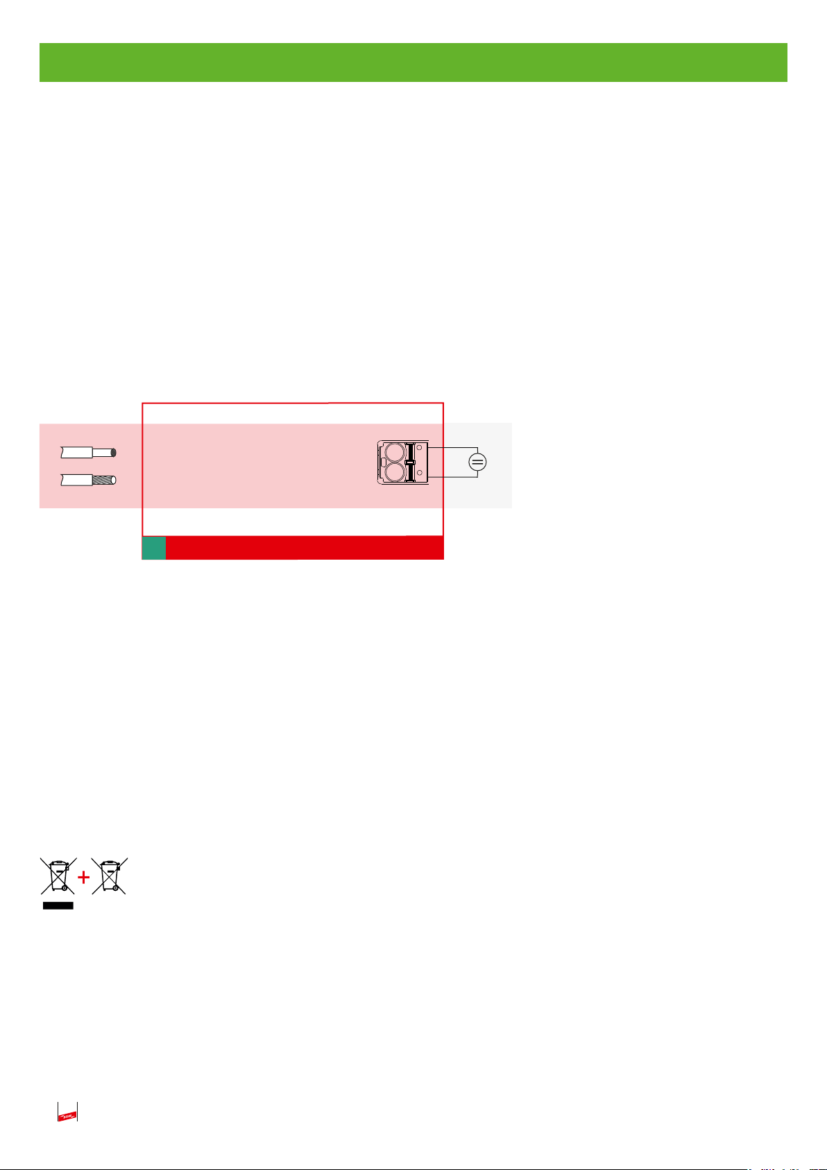
8. External power supply (9…32 V d.c.)
(see also Fig. 8)
Continuous and undisturbed supply of the device
Permissible range: 9-32 V d.c. / 150…50 mA
Galvanically isolated
Required for performing a self-test
Does not replace the battery
Also supplies the 4…20 mA output
max. 2.5 mm²
Externe
Spannungsversorgung/
External power supply
(9 ... 32 V DC, 2W)
Fig. 8
Fig. 8
+ (-)
- (+)
9. USB interface (only accessible to manufacturer)
In the form of a USN 2.0 type B socket
Galvanically isolated
e.g. power supply unit
+
of type PSU DC24 30W
Part No. 910 499
20
Equipment and batteries should not be disposed of in the normal household waste.
For more Information please refer to our website:
www.dehn-international.com
10. Technical data
Type
Typ VCSD 40 IP65
Part No.
Transient discharge current (10/350 µs)
Transient discharge current (8/20 µs)
Temporary discharge current (16.7 Hz, 50 Hz, 60 Hz)
Temporary discharge current (16.7 Hz, 50 Hz, 60 Hz)
Temporary discharge current (16.7 Hz, 50 Hz, 60 Hz)
1,1 kA
500 A
40 A
Long-term discharge current transient (up to 1 ms)
Transient limiting voltage (a.c.
Temporary limiting voltage (a.c.
Temporary limiting voltage(a.c.
Long-term limiting voltage (a.c.
Frequency range (a.c.)
) (1 ... 20 ms)
rms
) (20 ... 100 ms)
rms
) (100 ... 200 ms)
rms
) (> 200 ms)
rms
≤ 940V (1 kV acc. to AfK 3)
≤ 660V (1 kV acc. to AfK 3)
≤ 400V (1 kV acc. to AfK 3)
max. 50 V (adjustable from 3 ... 50 V)
16.7 Hz, 50 Hz, 60 Hz
Max. d.c.voltage in discharge mode
Max. leakage current in non-discharge mode at T
Power supply (internal)
= 20°
amb
external voltage; 9 V battery integrated
Current consumption (internal, typically at an earth resistance of 1 Ω)
< 2A (U
< 0.5A (U
Power supply (external, optional)
9 ... 32 V d.c., min. 0,5 A
Operating temperature range (TU)
Terminals 1, 2
M10 screw terminals, cross-sectional area of 35…50 mm
PE teminal
Housing material
coated sheet steel, RAL 7035, transparent door with safety glass
Degree of protection
Digital output / type of contact
Switching capacity (a.c.)
Switching capacity (d.c.)
max. 230 V / max. 0.6 A
max. 220 V / max. 2 A / max. 60 W
Digital input / type of contact
Contact data
Cross-sectional area of the signal lines
Dimensions
max. 9 V / 1 mA / 100 Ohm
max. 2.5 mm
400 x 300 x 150 mm
Weight
PU
VCSD 40 IP65
923 401
100 kA
100 kA
(up to 200 ms) *1)
rms
(up to 1s)
rms
(permanently) *2)
rms
≤ 1,25kV
±7Vd.c.
max. 500 µA
< 1A (U
-40 °C ... +80 °C
M8 (external)
make contact
make contact
< 5 V)
a.c.
. 5 - 6 V)
a.c
a.c.
IP 65
2
solid / flexible
12.1kg
1pc.
> 6 V)
2
*1) Derating depends on long-term discharge current and the ambient temperature
*2) Derating depends on the ambient temperature
21
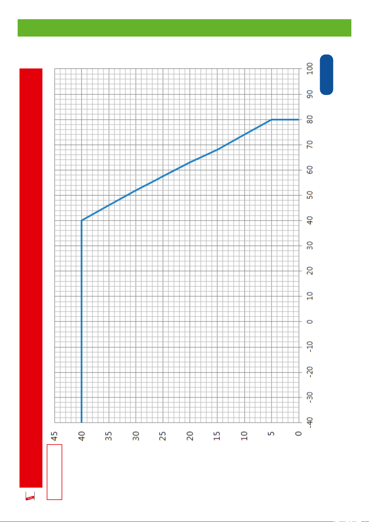
11. Derating for a long-term discharge current
in °C
amb
T
Derating for the long-term discharge current as a function
of the ambient temperature in the steel housing
22
rms
in A
stat
I
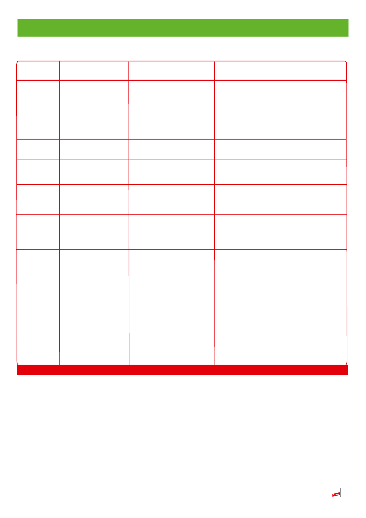
12. Diagnosis / Fault analysis
Binary code
0 0 1
*1)
0 1 0
0 1 1
1 0 0
1 0 1
*2)
Description
Permissible long-term
discharge current
exceeded
Temperature monitoring
activated
Faulty spark gap
Electronic failure
Low battery voltage
Voltage failure
Cause
I
see 11, page 22
stat
Thermal overload of
the device
Spark gap is overloaded
Electronic failure
Control electronics is faulty
Battery is empty
Capacitor voltage is exceeded
by +/- 7 V d.c.
Actions to be taken
Press the Reset button, if this fault occurs
again, compare the technical requirements
with the
performance data of the VCSD (observe the
derating depending on the ambient temperature!), please contact our service hotline at
+49-981-906-0
Replace the protection module (Part No. 961
010) and press the Reset button
Press the Reset button, if this fault occurs again,
please contact our service hotline at
+49-981-906-0
Replace the battery (Part No. 767 715) and
press the Reset button
d.c. potential at the pipeline is too high, if
required, check cathodic protection setting
and press the Reset button
Please contact our service hotline at
+49-981-906-0
1 1 0
Tabelle 1
Table 1
Faulty power
electronics
Self-test failed: Faulty power
electronics (indication after
pressing the self-test button;
as long as the external supply
voltage is connected, the
failure mode “1 1 0” lights
up in combination with the
self-test LED (red), after
disconnecting the external
supply voltage
the self-test LED goes out
and only the failure mode
“1 1 0” lights up).
*1) and *2)
Temporary occurrence of these failure modes is considered uncritical and therefore the device is capable of
automatically resetting these failure modes up to three times!
The device is automatically restarted after:
- *1) one hour
- *2) two minutes
Only if the same fault occurs four times in a row and an automatic restart was not successful (i.e. restart with
a fault that is still present or present again),
the device is finally switched off. This can only be reset by pressing the Reset button.
23
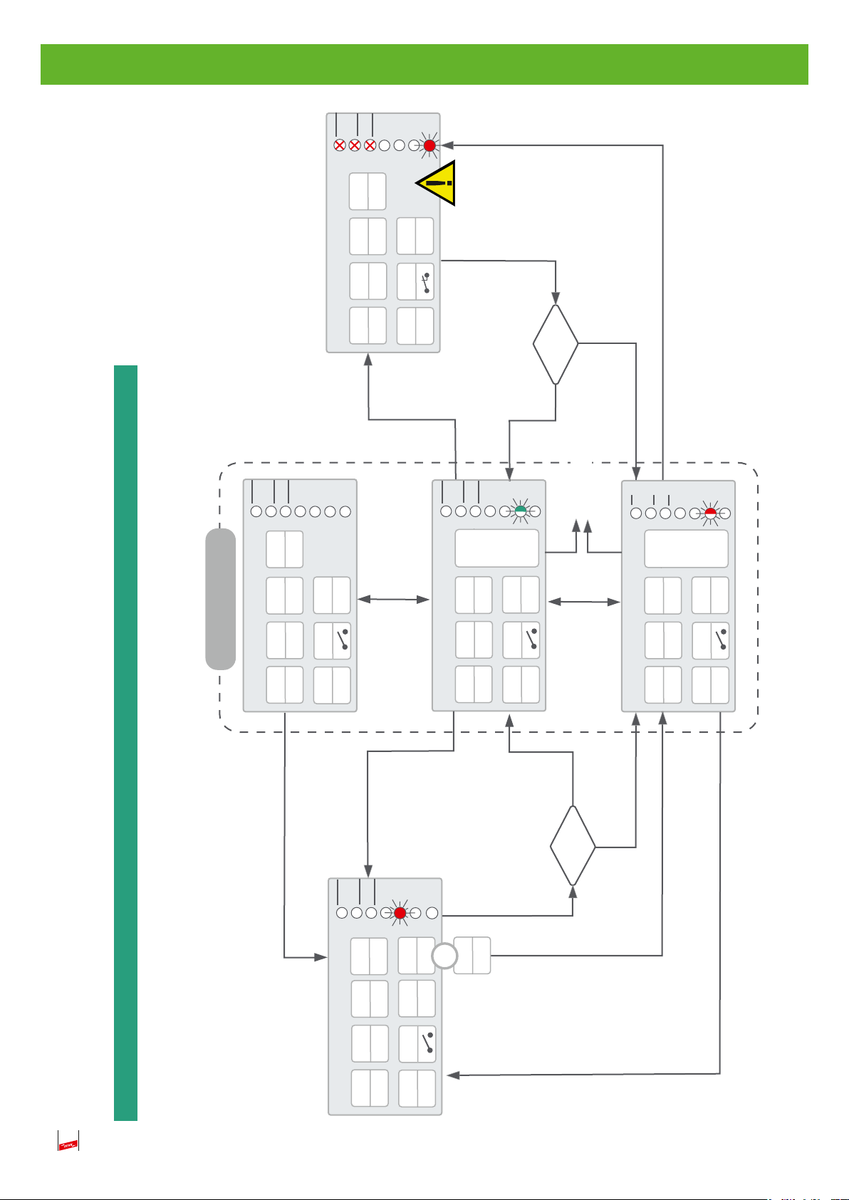
off
check
Selbsttest
VCSD aus /
Status
Fehlerstatus
standard operation
off
check
Uth
check
on
VCSD
th
U
VCSD
PS
fault in switch-off mode
Selbsttest
VCSD aus /
Status
Fehlerstatus
off
PU
off
D OUT
off
off
off
PU
D OUT
4-20 mA
Power
on
off
22,8
failure mode
check
Uth
VCSD
resetorrestart
Selbstest
VCSD aus /
cap
-U
-battery
check
on
after 1h or
Status
Fehlerstatus
temp
-I
off
PU
D OUT
2 min
AC
U
< Uth
?
> Uth
maloperation
th
> U
check
-battery
-U
on
Uth
on
VCSD
failure mode
Selbsttest
VCSD aus /
Status
cap
max
cont-Itemp
-T
-I
PU
D OUT
-V
Fehlerstatus
gate
on
Flow chart of the operating modes
PS
operational
Digital IN
Standby
closed
off
4-20 mA
Digital IN
closed
Selbsttest
VCSD aus /
off
check
th
U
50 V
off
VCSD
PS
off
manual switch-off mode
monitoring mode
Fehlerstatus
Status
ext
+
on
U
off
PU
D OUT
4,0
4-20 mA
PS
on
Digital IN
open
AC
U
>50 V
4,0
4-20 mA
< Uth
PS
on
discharge mode
4-20
4-20 mA
Digital IN
closed
?
AC
U
> Uth
24

Monitoring of the following parameters
check
Critical
- off ...no monitoring
No
fault
Yes
Monitoring parameters ok, if..
d.c.
> 6.0 V
batt
Battery Battery voltage U
d.c.
< ± 7.0 V
cap
d.c.. potential of the pipeline U
cap
U
< 40 A
Permissible continuous current I
I
rms
< 85°C
max
cont
Activation of the power unit (PU) active
Permissible temperature T
gate
max
cont
V
T
Not influenced
ext
VCSD at Pipeline
Important note:
VCSD
The system is capable of automatically resetting uncritical faults!
- on Low impedance Influenced
the input
- off High impedance
U
External power supply 9 - 32 V
- on ...connected to the VCSD.
Meaning of the icons
PU
Semi-conductor switch of the power unit (PU)
- on ...switched on
4-20 mA
- off ...switched off
mA 4 8 12 16 20
A 0 10 20 30 40
…interface off due to missing power supply
Analogue current interface 4 - 20 mA
- off
- < 4 mA …wire breakage or missing external power supply
- 4.0 mA ...on, but no discharge mode
- 4 - 20 mA …discharge mode, discharge current of 0 - 40 A corresponds to 4 - 20 mA
)
th
> 1.5 V
AC
(Digital OUT) floating contact for centralised fault indication
- 22.8 mA …fault in switch-off mode, failure mode present
PS
Internal power supply unit for supply from the a.c. pipeline potential
- off ...switched off
On-site intervention is required in case of critical faults! (see 12.)
- Standby ...operational, waiting for input voltage UAC- on ...in operation due to U
D OUT
. . .open
Actual response threshold (U
th
U
Signal (contact closed) only in case of failure mode
- …closed
-
-off …response threshold is not monitored
-check …response threshold is monitored
-50 …stopped, a threshold of 50 V is monitored if the device is operated via
the external power supply
-on . . .response threshold was exceeded
25
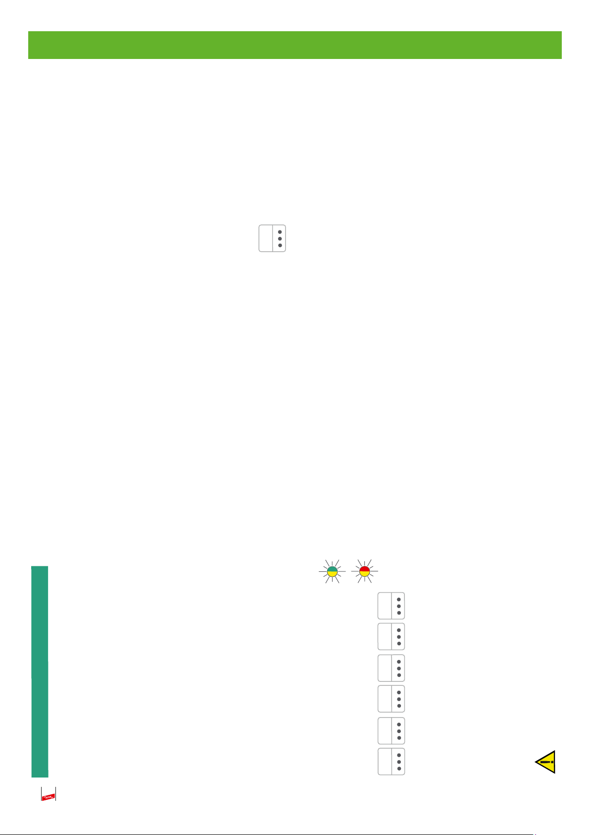
d.c.
th
U
is exceeded.
)
th
(U
Terms and definitions:
- operational, monitoring mode and discharge mode. The device is operational.
Includes the operating modes
Standard operation
26
d.c.
9 -32 V
ue to an a.c. interference in case of a terminal voltage > 1.5 V
when applying an external supply voltage
Operating error
This mode remains active until the minimum discharge current is undercut.
The discharge mode is activated if the actual response threshold voltage
Threshold voltage
- d
or
-
The device changes from operational to the monitoring mode
Power
or
- The response threshold was changed without pressing the Release button. The last released response threshold remains active.
Present if:
in monitoring mode
appears on the device:
In both cases, the following indication
- An invalid response threshold is released. 3 V (if the value is undercut) or 50 V (if the value is exceeded) are automatically set.
in discharge mode
OUT
D
4-20 mA
check
VCSD
PS PU
>>> unchanged according to the operating mode
Digital IN closed
If the digital input is closed, the device is put into the switch-off mode (also if it is operational) until the contact is opened again.
The device directly changes back to the currently required operating mode.
Failure mode
Monitoring the parameters allows to detect a critical fault and to automatically switch the device to a safe state. The failure mode is displayed on the device
(LED X X X) and generally via the 4-20 mA current interface (22.8 mA).In case of uncritical faults, the device is automatically restarted up to three times after
one hour or 2 minutes.Only if the same fault occurs more than three times in a row, a critical fault is generated and the device remains in fault in switch-off
mode.
On-site operator intervention, namely pressing the “Reset failure mode” button, is required (see also 4.3.2, page 16)!

Spare part list / accessories
Block battery 9V lithium-manganese dioxide (Li-Mn O
Power supply unit PSU DC24 30W
Part No. 910 499
Surge protective devices
- Digital IN: BXT BAS Part No. 920 300 and BXT ML4 B 180 Part No. 920 310
- Digital OUT: BXT BAS Part No. 920 300 and BXT ML4 B 180 Part No. 920 310
- Analog OUT: BXT BAS Part No. 920 300 and BXT ML4 BE 24 Part No. 920 324
) battery
2
27

Surge Protection DEHN + SÖHNE Hans-Dehn-Str. 1 Tel. +49 9181 906-0
Lightning Protection GmbH + Co.KG. Postfach 1640 www.dehn-international.com
Safety Equipment 92306 Neumarkt
DEHN protects. Germany
 Loading...