


Bedienungsanleitung
Durchgangsprüfer EP4
Überspannungsschutz
Blitzschutz / Erdung
Arbeitsschutz
DEHN + SÖHNE
GmbH + Co. KG
Postfach 1640
92306 Neumarkt
Tel. +49 9181 906-0
Fax +49 9181 906-1100
www.dehn.de
info@dehn.de
© Copyright 2011 DEHN + SÖHNE / protected by ISO 16016
Publication No. 1567 / UPDATE 01.07 Id No. 050551
Blitzschutz / Erdung

Kurzanleitung; Durchgangsprüfer EP4
Diese Kurzinfo hilft Ihnen für den Schnelleinstieg. Bitte beachten Sie zu Ihrer
Sicherheit und für weitere Informationen die ausführliche Bedienungsanleitung
Funktion
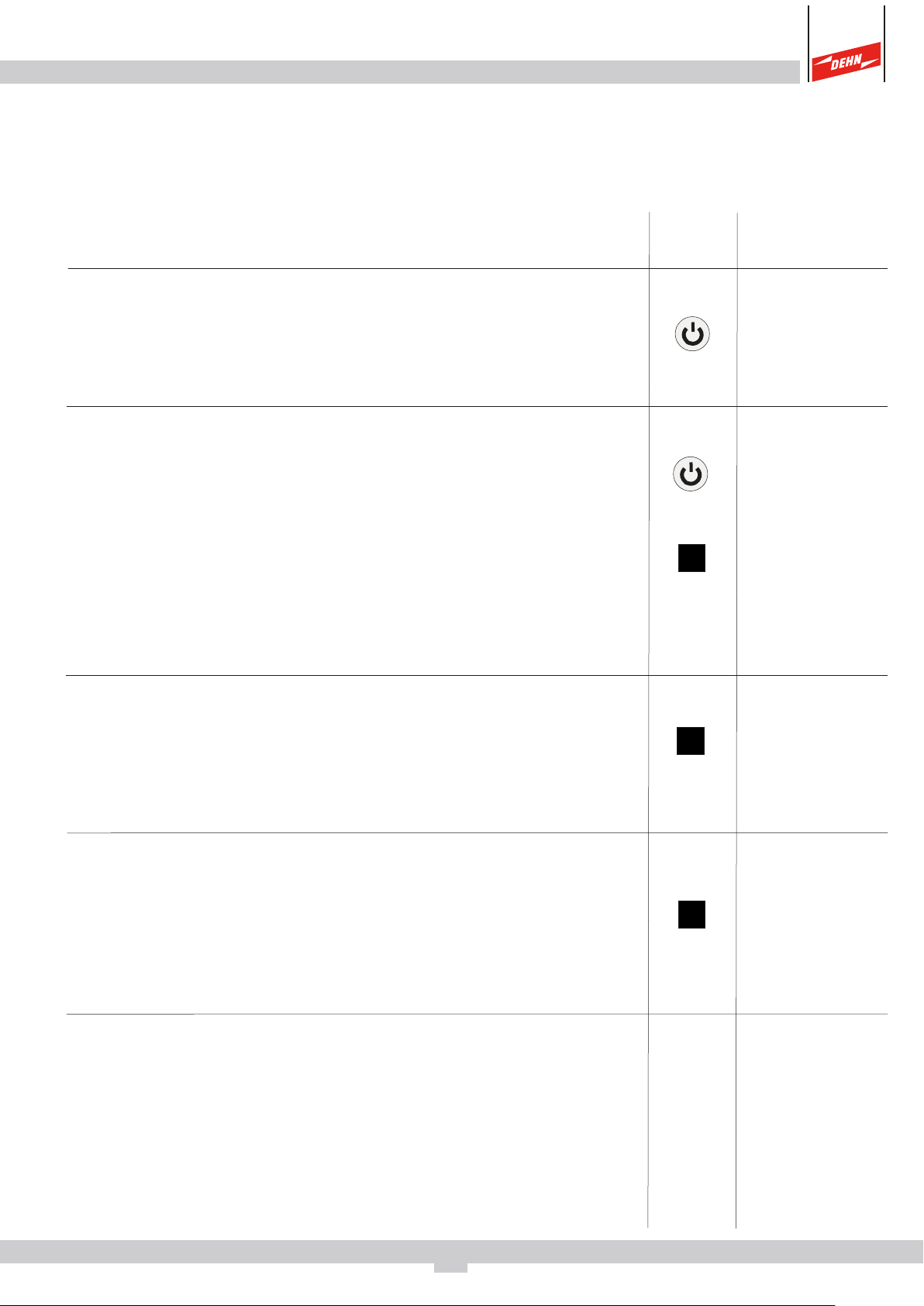
Einschalten
Messbereitschaft wird durch "+1" signalisiert (solange
der Taster beim Einschalten gedrückt bleibt, erfolgt ein
Eigentest)
Nullabgleich "CAL" mit Messleitung
Beide Taster gleichzeitig drücken.
Solange "CAL" angezeigt wird (ca. 15 s) Messleitung
(beliebige Leitung bis max 3 W) mit Prüfspitze verbin-
den.
Der Wert wird abgespeichert und bei Messungen auch
nach Aus- und Einschalten des EP4 bis zum nächsten
Nullabgleich verwendet.
Taster Betätigung
kurz
und kurz
Messbereich wählen
Der Lo Ω-Bereich arbeitet mit einem Messstrom von
200 mA und wird automatisch bei Widerstandswerten
kleiner 10 Ω eingeschaltet.
Standardmessung
Geeignet für Prüfung von Widerständen ohne Speicherung. Messwert erscheint auf Anzeige, nach einer Messung erscheint nach 2 sec. wieder "+1", welches Prüfbereitschaft signalisiert.
Polwechsel für Standardmessung
Richtung des Messstroms wird gewechselt und durch
(+) oder (-) im Display angezeigt. Bei Erdungsprüfungen
mit Gleichspannungen müssen (+)-und (-) Werte ermit-
+/-
automatisch
> 2 sec.
kurz
telt werden, um falsche Ergebnisse bei Differenzen zu
erkennen.
2

Automatikmessung
Funktion
Taster Betätigung
Geeignet für Lo Ω Prüfung (< 10 Ω) mit einem Messstrom von 200 mA. Die Richtung des Messstromes wird
automatisch gewechselt und durch (+) oder (-) im Dis-
play angezeigt.
Abruf gespeicherter (+) und (-) Minimalwerte
Nach einer Automatikmessung wird der kleinste gemessene Widerstandswert auf dem Display angezeigt.
Zum Vergleich des kleinsten (+)- und (-) Messwertes
durch +/- Taster wechseln. Weichen beide Werte stark
voneinander ab, siehe Bedienungsanleitung.
Ausschalten
Ohne Tasterbetätigung schaltet das Gerät zur Schonung
+/-
+/-
> 2 sec.
kurz
kurz
kurz
der Batterie nach 20 sec. automatisch aus.
Signale
Akustisches Signal bei Durchgang < 1Ω während der Betätigung des
Tasters . Warnton und rote LED bei Fremdspannung ab 10 V bis 400 V
(Spannung in Volt wird angezeigt)
3

Bedienungsanleitung, Durchgangsprüfer EP4
1. Verwendung
Der Durchgangsprüfer EP4 ist ein digital anzeigendes Niederohm-Messgerät
zur gefahrlosen Überprüfung von Leitungswiderständen bis 2000 kΩ in Elektroanlagen mit Nennspannungen bis 500 V.
Mit ihm können Sie größere Schutzleiter-, Erdungs- und Potentialausgleichssowie Abschirm- und Blitzschutzanlagen schnell und sicher überprüfen.
Zuverlässige Messergebnisse werden durch den Messstrom von 200 mA und
die automatische Minimalwerterfassung erreicht.
Mit Hilfe beliebiger Messleitungen (bis zu 3,5 Ω) werden Widerstände zwischen
einem Bezugserder (z.B. Potentialausgleichs-Schiene) und den Prüfstellen gemessen.
Der Messleitungs-Widerstand wird beim automatischen Nullabgleich
abgespeichert und bei den Messungen berücksichtigt.
2. Sicherheit
Sie haben sich für ein Gerät entschieden, das Ihnen ein hohes Maß an Sicherheit
bietet. Es entspricht den Bestimmungen EN/IEC 61557-1+4 (VDE 0413 Teil 1+4)
und EN/IEC 61010.
⇒ Um eine gefahrlose und richtige Anwendung sicherzustellen, ist es
unerlässlich, dass Sie diese Bedienungsanleitung vor der ersten
Verwendung vollständig lesen.
Bei dem Einsatz Ihres Gerätes ist diese Anleitung in allen Punkten sorgfältig
zu befolgen.
Bitte beachten Sie folgende Sicherheitsvorkehrungen:
⇒ Der EP 4 darf nur in Stromnetzen mit Betriebsspannungen bis maximal
500 V eingesetzt werden.
⇒ Es darf nur an spannungsfreien Anlagenteilen gemessen werden.
4

⇒ Verwenden Sie berührungsisolierte Stecker (IP 2x mit Kragen) für
die Buchse des EP4, wenn Sie an Messstellen prüfen, an denen
Spannungen vorkommen können.
Bei Anlegen des eingeschalteten Gerätes an eine Spannung über ca. 15 V erfolgt
ein akustisches und optisches Warnsignal (siehe 4.4). In diesem Fall ist das Messobjekt erst spannungsfrei zu schalten, bevor Widerstandsmessungen durchgeführt
werden.
3. Inbetriebnahme
In Ihr Gerät haben wir bereits eine 9 V-Batterie IEC 6 LR 61 eingesetzt. Es ist
betriebsbereit. Beachten Sie vor der ersten Inbetriebnahme oder nach längerer Lagerung Ihres Gerätes den Abschnitt 5.
Einschalten:
⇒ Taster kurz drücken, (Anzeige +1 und mittlere LED).
Die Anzeige +1 bedeutet Messbereitschaft
Ausschalten:
⇒ Taster
erneut drücken. Das Gerät schaltet sich automatisch aus,
wenn etwa 20 sec. kein Taster betätigt wird.
Eigentest:
⇒ beim Einschalten Taster
gedrückt halten; wenn alle Segmente der LCD,
3 LEDs, ein akustisches Signal ertönt und nach Loslassen des Tasters +1
die mittlere LED anzeigen, ist das Gerät in Ordnung.
Fällt bei der Eigenüberprüfung eine Anzeige auch nur teilweise aus oder
wird keine Funktionsbereitschaft angezeigt, darf der EP4 nicht mehr
verwendet werden und muss zur Reparatur eingeschickt werden.
⇒ Wird die Fehlermeldung “Fuse ERR” angezeigt, ist das Gerät nicht mehr
betriebsbereit und die Sicherung gegen Überspannung muss vom
Hersteller getauscht werden.
5

Batterietest:
⇒ Wird nur noch eine leeres Batteriesymbol angezeigt, muss die Batterie
ersetzt werden ( siehe Abschnitt 5 ).
4. Messen und Prüfen
4.1 Allgemeines
Tasterfunktionen:
Taster
Taster
: Ein-/Ausschalten (3), Selbsttest (3), Nullabgleich (4.3)
: Nullabgleich (4.3), Messen (4.4)
Taster +/-: Polaritätswechsel (4.4), Automatikmodus, Messwerte abrufen (4.4)
4.2 Messaufbau
Zwischen dem Bezugserder (z.B. Potentialausgleichs-Schiene oder Betriebserder) und dem EP4 kann jede beliebige Messleitung (bis etwa 3,5 Ω) verwendet werden, die sich nach Abschnitt 4.3 abgleichen lässt.
Es können Messstellen erreicht werden, die über 100 m vom Bezugserder
entfernt sind. In Umgebungen mit starken Feld-Einflüssen sollte die Leitung
völlig abgewickelt sein, damit induktive Einflüsse vermieden werden.
⇒ Klemmen Sie die Messleitung gut leitend an den Bezugserder (evtl.
Korrosion beseitigen).
⇒ Stecken Sie das freie Ende der Messleitung in die Buchse des EP4.
Bei Verwendung der Abrollhaspel muss die mitgelieferte 1 m-Prüfleitung
in die Buchse der Haspel gesteckt werden.
6

4.3 Nullabgleich
Vor jeder Mess-Serie müssen Sie den EP4 zusammen mit der Messleitung
(siehe Messaufbau 4.2) abgleichen. Dies ist auch dann erforderlich, wenn
dieselbe Messleitung nach einiger Zeit wiederverwendet wird, um
Temperatureinflüsse zu berücksichtigen. Der Abgleich erfolgt automatisch für
den Messbereich 10 Ω und 200 Ω mit 20 - 200 mA.
⇒
Drücken Sie während des Einschaltens den Taster
und gleichzeitig den
Taster
In der oberen Zeile erscheint ein Wartebalken.
⇒ Setzen Sie die Messspitze sofort mit sicherem Kontakt auf den
Bezugserder.
⇒
Halten Sie den Kontakt solange “CAL” im Display erscheint und der
Ladebalken nicht abgelaufen ist. Der Abgleich ist abgeschlossen, wenn
+1 erscheint und die mittlere LED leuchtet.
Der Widerstand der Messleitung bleibt gespeichert, bis ein neuer Nullabgleich stattfindet. Der Wert wird nicht gelöscht wenn das Gerät ausschaltet
oder die Batterie gewechselt wird.
Wenn die Meldung “Err” erscheint, ist der Nullabgleich misslungen und
In der Anzeige erscheint “CAL” und die POL +/- LED leuchtet.
.
muss wiederholt werden. Dies kann passieren, wenn die Prüfspitze beim Abgleich abrutscht oder die Messleitung zu hochohmig ist (> 3,5 Ω ).
⇒
Zur Kontrolle sollten Sie die erste Messung (siehe 4.4) immer direkt
am Bezugserder durchführen.
Das Ergebnis sollte für beide Polaritäten < 0,04 Ω sein.
Aufgerollte Leitungen können Fehlmessungen durch Induktivitäten
verursachen.
7

4.4 Messen
Nach Messaufbau (siehe 4.2) und Nullabgleich (siehe 4.3) ist die Ausrüstung
für Messungen bereit.
Es können Standard- oder Automatikmessungen mit oder ohne Polwechsel durchgeführt werden. Die Stromflussrichtung wird durch + oder - im Display angezeigt.
Das angezeigte Vorzeichen gilt für die Geräteprüfspitze.
⇒
⇒
⇒ Messspitze möglichst senkrecht mit sicherem Kontakt aufsetzen
Wenn die rote LED blinkt und ein akustisches Signal ertönt, ist eine Fremdspannung vorhanden!
Die Prüfung muss an dieser Messstelle abgebrochen werden (siehe Fremdspannungen 4.5)
Kurze Warnsignale können durch induktive Spannungen oder statische Aufladungen verursacht werden und beeinflussen die Messung nicht.
Messstelle von evtl. Korrosion oder Farbe säubern.
Gerät mit Taster
grüne LED)
einschalten (Anzeige der Messbereitschaft: +1 und
4.5 Standardmessung
Taster
Bei Messwerten kleiner 10 Ω wechselt der EP4 automatisch in den LO- Ω
Modus und misst mit einem Messstrom von 200 mA.
In der Anzeige erscheint “Lo- Ω” und die rechte LED signalisiert 200 mA Mess-
strom. Befindet sich der Messwert außerhalb des Messbereichs
(> 1999 kΩ) wird “OL” (Overflow) angezeigt.
solange drücken, bis ein konstanter Messwert erscheint.
8

Polaritätswechsel:
Der Polaritätswechsel ist erforderlich, wenn galvanische Spannungen das
Messergebnis beeinflussen können.
⇒
Nach erfolgter Messung mit positiver Polung (s.o.): Taster +/- drücken
(Anzeige der Messbereitschaft mit anderer Polung: -1 und grüne LED)
negative Messung in gleicher Weise durchführen.
Sollten die Werte stark voneinander abweichen, liegen voraussichtlich
galvanische Spannungen an.
Beide Messungen wiederholen. Wenn die Wiederholungsmessungen zu
ähnlich unterschiedlichen Werten führt, ist der Mittelwert zwischen +
und - anzunehmen.
4.6 Automatikmessung:
Die Automatikmessung ist nur für Messungen von Widerständen < 10 Ω
geeignet und wird immer mit einem Messstrom von 200 mA durchgeführt.
(Prüfung nach VDE 0413)
⇒
Taster +/- gedrückt halten bis die POL +/- LEDs schnell aufleuchten und
“Auto” im Display angezeigt wird.
⇒
Taster
⇒ Die Messung dauert ca. 3 Sekunden, der Polwechsel wird automatisch
durchgeführt
⇒ Nach der Messung können Sie durch Drücken des Taster +/- zwischen
dem kleinsten gemessenen Widerstandswert mit + Polarität und –
Polarität wechseln. Die Messergebnisse werden bis zu einer erneuten
Messung gespeichert. Um eine weiter Messung durchzuführen drücken
Sie bitte kurz den Taster .
⇒
Um zur Standardmessung zurückzukehren drücken Sie den Taster +/- bis
kurz drücken um die Automatikmessung zu starten
die POL +/- LEDs schnell aufleuchten und “Auto” im Display erlischt.
9

Fehler:
Falls Sie kein Messergebnis erhalten, könnte eine Auswertung, z.B. durch
Abrutschen der Prüfspitze oder durch stark schwankende Impedanzen, außerhalb
des gewählten Messbereichs liegen. Sie sollten die Messung wiederholen. Sollten
auch Wiederholungsmessungen keine eindeutigen Ergebnisse liefern, müssen
Sie längere Standardmessungen mit beiden Polaritäten vornehmen und die
Messwerte selbst beurteilen.
4.5 Fremdspannungen
Wird der eingeschaltete EP4 an eine Spannung (15 bis 400 V) angelegt, werden
Sie durch die blinkende rote Leuchtdiode und einen Signalton gewarnt.
Gleichzeitig wird die Spannungshöhe auf der LCD angezeigt. Das Gerät ist bis
400 V durch Halbleiter geschützt. Bei höheren Spannungen spricht eine Sicherung
an, die nur vom Hersteller ausgetauscht werden kann. Die Sicherung wird beim
Selbsttest des Gerätes automatisch überprüft (siehe 3.).
5. Wartung
Der aktuelle Zustand der Batterie wird über die dreistufige Batterieanzeige im
Display angezeigt. Bei voller Ladung werden alle drei Segmente angezeigt.
Erscheint ein nur noch halbvolles Batteriesymbol, sind noch viele Messungen
möglich. Wird ein leeres Batteriesymbol angezeigt, ist die Batteriespannung zu
gering, dann müssen Sie die Batterie durch eine neue ersetzen. Je nach Batterietyp
können Sie in diesem Zustand noch mindestens 5 Messungen durchführen.
Achtung: Wenn das leere Batteriesymbol blinkt, sind die Messwerte nicht mehr
zuverlässig, die Batterie muss dann sofort gewechselt werden.
Zum Batteriewechsel muss der rückseitige Deckel abgeschraubt werden.
⇒ Es dürfen nur folgende Batterien eingesetzt werden:
9V-Block IEC 6 LR 61 oder 6 F 22.
⇒ Die Stecker, Buchsen und Kontakte sind sauber zuhalten und bei Bedarf
zu reinigen. Überzeugen Sie sich regelmäßig, dass die Batterie nicht aus gelaufen ist.
10

Bei ausgelaufener Batterie müssen Sie das Elektrolyt vollständig entfernen
und eine neue Batterie einsetzen.
⇒
Bei längerer Lagerung ist der EP4 ohne Batterie an einem trockenen und
sauberen Ort bei Temperaturen von -10° bis + 70°C zu verwahren.
⇒ Das Kunststoffgehäuse können Sie mit einem mit Alkohol (Isopropanol)
oder Seifenwasser befeuchteten Tuch reinigen. Nicht mit Mitteln reinigen,
die Aceton oder
6. Technische Daten
Widerstands-Messgerät nach EN/IEC 61557-1 EN/IEC 61557–4 und EN/IEC 61010
Messbereiche: 0,01
Genauigkeit: 1,5% +/- 4 Digit bei 20°C
Messstrom: < 10
Leerlaufspannung: > 4 V
Abgleich der Messleitung: über automatische CAL-Funktion bis 3,5 Ω
Digitalanzeige: 10 mm hohe zweizeilige LCD-Anzeige, 3 1/2-stellig,
Überlaufanzeige durch “OL”
Spannungsanzeige: rote LED und akustisches Warnsignal sowie Anzeige
ähnliche Lösungsmittel enthalten.
...1999 kΩ
Ω
200 mA konstant, > 10 Ω 20 mA ... 1 µA
Ω
des Wertes
Überspannungsschutz: bis zur Nennspannung 400 V reversibel durch Halb leiter, über 400V bis 500 V durch Spezialsicherung
(Prüfung durch Selbsttest)
Arbeitstemperatur: -10 ... +50°C
Versorgung: Batterie 9 V-Block, IEC 6 LR 61 oder 6 F 22
automatische Abschaltung erfolgt nach 20 sec. ohne
Messung. Mehrstufige BAT-Anzeige
EMV-Anforderung: DIN-EN 61326
Gehäuse: aus schlagfestem ABS mit unzerbrechliche Anzeige abdeckung
Schutzart IP 65; 60 x 230 x 40 mm, 180 g
11

Überspannungsschutz
Blitzschutz / Erdung
Arbeitsschutz
DEHN + SÖHNE
GmbH + Co. KG
Postfach 1640
92306 Neumarkt
Tel. +49 9181 906-0
Fax +49 9181 906-100
www.dehn.de
info@dehn.de
© Copyright 2011 DEHN + SÖHNE / protected by ISO 16016

INSTRUCTIONS for Use
EP4 Continuity Tester
Surge Protection
Lightning Protection / Earthing
Safety Equipment
DEHN + SÖHNE
GmbH + Co.KG.
Hans-Dehn-Straße 1
Postfach 1640
92306 Neumarkt
Germany
Tel. +49 91 81 / 9 06 - 0
Fax +49 91 81 / 9 06 - 1100
www.dehn.de
info@dehn.de
© Copyright 2011 DEHN + SÖHNE / protected by ISO 16016
Publication No. 1567 / UPDATE 01.07 Id No. 050551
Lightning Protection /
Earthing
Brief instructions for EP4 continuity testers
These brief instructions allow to start working with the EP4 continuity tester right
away. For safety reasons, please observe the additional information provided in
the detailed instructions for use.
Function
Switching the continuity tester on
"+1" indicates that the device is operational (as long
as the button is kept pressed when switching on the
device, a self-test is performed)
Zero balancing "CAL" with measuring cable
Press both buttons at the same time.
Connect the measuring cable (any cable up to max. 3
W) to the test prod as long as "CAL"
(about 15 s).
The value is stored and used for
is displayed
measurements until a new zero balancing is performed.
This value is not deleted if the EP4 continuity tester is
switched on or off.
Button Press
shortly
and
shortly
Selecting a measuring range
In case of resistance values of less than 10 Ω, the EP4
continuity tester automatically switches over to the Lo
Ω mode and measures with a measuring current of 200
mA.
Standard measurement
Standard measurements are performed to measure resistances without storing them. The measured value is displayed. "+1" appears again two seconds after a
measurement, meaning that the EP4 continuity tester
is operational.
Change of polarity during standard
measurements
The direction of the measuring current is changed and
displayed by (+) or (-). In case of earth testing with direct
+/-
automatically
> 2 sec.
shortly
currents, the (+) and (-) values must be determined to
be able to detect incorrect results in case of deviations.
2

Function
Automatic measurement
Button Press
Suitable for Lo Ω measurements (< 10 Ω) with a measuring current of 200 mA. The direction of the measuring
current is automatically changed and displayed by (+)
or (-).
Display of stored minimum (+) and (-) values
After an automatic measurement, the lowest resistance
value measured appears on the display. Press the +/button to compare the lowest (+) and (-)values
measured. See detailed instructions for use, if both values
significantly differ from another.
Switching the continuity tester off
If no button is pressed, the EP4 continuity tester automa-
+/-
+/-
> 2 sec.
shortly
shortly
shortly
tically switches off after 20 seconds to save battery
power.
Signals
Acoustic signal in case of a conductivity < 1 Ω if the button is pressed.
Acoustic signal and red LED in case of an external voltage from 10 V to 400 V
(voltage is displayed in volts).
3

Instructions for use for EP4 continuity testers
1. Use
The EP4 continuity tester is a digital low-impedance measuring device for
reliably measuring cable resistances up to 2000 kΩ in electrical installations
with nominal voltages up to 500 V.
It allows to quickly and reliably test large-scale protective conductor, earthtermination, equipotential bonding and lightning protection systems.
A measuring current of 200 mA and the automatic detection of minimum values
ensure reliable measurement results.
Any measuring cable (up to 3.5 Ω) can be used to measure resistances between
a reference earth electrode (e.g. equipotential bonding bar) and other measuring
points.
The resistance of the measuring cable is stored during automatic zero balancing
and considered for future measurements.
2. Safety
You have chosen a measuring device that provides a high degree of safety. It
complies with the requirements of EN/IEC 61557-1+4 and EN/IEC 61010.
⇒ To ensure safe and proper use, completely read these instructions for use
before using the EP4 continuity tester for the first time.
Carefully follow all points included in these instructions for use when
using the EP4 continuity tester.
The following precautions must be taken:
⇒ Only use the EP4 continuity tester for power supply systems with a
maximum operating voltage of 500 V.
⇒ Measurements may only be performed on de-energised parts of
an installation.
4

⇒ Insert a shock-proof plug (IP 2x with shrouded contacts) in the socket of
the EP4 continuity tester when performing measurements on measuring
points that may be energised.
When the device is switched on and connected to a voltage of more than 15 V,
an acoustic and visual alarm is provided (see 4.4). In this case, the test object
must be de-energised before performing resistance measurements.
3. Initial operation
A 9 V battery (IEC 6 LR 61) is already included in the scope of delivery of the
EP4 continuity tester. The device is thus operational. Observe section 5 of these
instructions for use prior to initial operation of the device or after extended
periods of storage.
Switching the device on:
⇒ Shortly press the button (+1 is displayed and the middle LED lights
up).
+1 indicates that the device is operational.
Switch the device off:
⇒ Press the button again. The device switches off automatically after
about 20 seconds if no button is pressed.
Self-test:
⇒ Keep the button pressed when switching on the device; the device is
in good order and condition if all LCD segments are displayed, the three
LEDs light up, an acoustic signal sounds and the middle LED lights up
when releasing the +1 button.
If the display fails during a self-test (completely or partly) or the device
does not indicate readiness for operation, the EP4 continuity tester must
be refrained from use and send in for repair.
⇒ If the “Fuse ERR” fault message is displayed, the device is no longer
operational and the fuse must be replaced by the manufacturer.
5

Battery test:
⇒ If the empty battery symbol is displayed, the battery must be replaced
(see section 5).
4. Measuring and testing
4.1 General
Button functions:
button: switching the device on/ off (3), self-test (4), zero balancing (4.3)
button: Zero balancing (4.3), measuring (4.4)
+/- button: Change of polarity (4.4), automatic mode, display measured
values (4.4)
4.2 Measurement set-up
Any measuring cable (up to 3.5 Ω) can be used between the reference earth electrode (e.g. equipotential bonding bar or system earth electrode) and the EP4 continuity tester. This measuring cable is calibrated according to section 4.3.
The EP4 continuity tester reaches measuring points that are more than 100
m away from the reference earth electrode. To avoid inductive interference,
the cable should be completely uncoiled in surroundings with strong field
effects.
⇒ Clamp the measuring cable to the reference earth electrode with good
electrical contact (remove corrosion, if required)
⇒ Plug the free end of the measuring cable into the socket of the EP4
continuity tester.
When using an uncoiler, plug the 1 m measuring cable supplied into the
socket of the uncoiler.
6

4.3 Zero balancing
Prior to each measurement series, the EP4 continuity tester must be
calibrated together with the measuring cable (see measurement set-up 4.2).
To consider temperature influences, this is also required if the same
measuring cable is reused after a while. Zero balancing is performed
automatically for a measuring range between 10 Ω and 200 Ω with 2 – 200
mA.
⇒
Simultaneously press the and button when switching on the
device. "CAL" is displayed and the POL +/- LED lights up.
A progress bar appears in the upper line.
⇒ Immediately position the test prod on the reference earth electrode and
ensure safe contact
⇒
Maintain contact as long as "CAL" and the progress bar are displayed.
Zero balancing is completed if +1 appears and the middle LED lights up.
The resistance of the measuring cable remains stored until a new zero
balancing is performed. The value is not deleted if the device is switched off
or the battery is replaced.
If the "ERR" message appears, zero balancing has failed and must be
repeated. This is the case if the test prod slips down or the resistance of the
measuring cable is too high (> 3.5 Ω).
⇒ The first measurement (see 4.4) should always be performed directly on
the reference earth electrode.
.
The result should be ≤ 0.04 Ω for both polarities.
Coiled cables may cause false measurements due to inductances.
7

4.4 Measuring
After the device has been connected to the reference earth electrode (see 4.2)
and zero balancing has been performed (see 4.3), the equipment is
operational.
Standard or automatic measurements with or without change of polarity can
be performed. The direction of the current flow is displayed by + or -. The
displayed algebraic sign refers to the test prod of the device.
⇒
⇒
⇒ Messspitze möglichst senkrecht mit sicherem Kontakt aufsetzen
If the red LED flashes and an acoustic signal sounds, external voltage
is present!
The measurement must be aborted at this measuring point (see external voltage
4.5).
Short warning signals caused by inductive voltages or static charges do not
interfere with the measurement.
Remove corrosion or paint from the measuring point, if required.
Press the button to switch on the device (operational if +1 is
displayed and green LED lights up).)
4.5 Standard measurement
Press the button until a constant measured value is displayed.
In case of measured values of less than 10 Ω, the EP4 continuity tester
automatically changes to the Lo Ω mode and continues measuring with a
measuring current of
The "Lo Ω" symbol is displayed and the right LED indicates a measuring
current of 200 mA. If the measured value is outside the measuring range (>
1999 kΩ), the "OL" (overflow) symbol appears.
200 mA.
8

Change of polarity:
Change of polarity is required if galvanic voltages may interfere with the
measurement result.
⇒
After measurements with positive polarity: Press the +/- button (-1 and
green LED indicate readiness for operation with different polarity).
Proceed the same way for measurements with negative polarity.
If the values significantly differ from another, galvanic voltages may be
present.
Repeat both measurements. If the results are similar to those taken
before, the mean value between + and – must be assumed.
4.6 Automatic measurements
Automatic measurements are only suited for resistance measurements
Ω.
They are always performed with a measuring current of 200 mA (tests
< 10
comply with VDE 0413).
⇒
Keep +/- button pressed until the POL +/- LEDs quickly light up and
"Auto" is displayed
⇒
Shortly press the button to start the automatic measurement.
.
⇒ The measurement takes about 3 seconds; change of polarity is
performed automatically.
⇒ After the measurement, you may change between the lowest resistance
value with + and – polarity by pressing the
+/-
button. The measurement
results are stored until the next measurement. Shortly press the
button to perform a new measurement.
⇒
To switch back to the standard measurement, press the
+/-
button until
the POL +/- LEDs quickly light up and “Auto” disappears.
9

Errors:
If no result is displayed, the evaluation may be outside the selected measuring
range, for example if the test prod slips down or impedances heavily fluctuate.
You should repeat the measurement. If the repeated measurement does not
provide a clear result, perform standard measurements with both polarities and
assess the measured values on your own.
4.5 External voltages
When the EP4 continuity tester is switched on and a voltage from 15 to 400 V
is applied, the red LED flashes and an acoustic signal sounds. At the same time,
the voltage is displayed on the LCD. Semi-conductors protect the device up to
400 V. In case of higher voltages, a fuse that can only be replaced by the
manufacturer trips. The fuse is automatically checked during the self-test of the
device (see 3.).
5. Maintenance
The current battery status is displayed via a three-stage battery indicator. All
three segments are displayed if the battery is fully charged. Many measurements
can still be performed if a half-filled battery symbol appears. If an empty battery
symbol is displayed, the battery voltage is too low and the battery must be
replaced. Depending on the battery type, at least five measurements can still
be performed.
Attention: If the empty battery symbol flashes, the measured values are no
longer reliable. Immediately replace the battery.
To this end, unscrew the rear cover.
⇒ Only use the following batteries:
9 V block battery (EC 6 LR 61 or 6 F 22).
⇒ Keep the plugs, sockets and contacts clean and clean them, if required.
Regularly check whether the battery has leaked.
10

If the battery has leaked, completely remove the electrolyte and insert a
new battery.
⇒ If the EP4 continuity tester is stored over an extended period, store the
device without battery at a dry and clean place at temperatures between
-10°C and +70°C.
⇒ Clean the plastic enclosure with a cloth dampened with alcohol
(isopropanol) or soap suds. Do not use cleaning agents containing
acetone or similar solvents.
6. Technical data
Continuity tester according to EN/IEC 61557-1, EN/IEC 61557-4 and EN/IEC 61010
Measuring ranges: 0.01
Accuracy: 1.5% +/- four digits at 20°C
Measuring current: < 10
Open-circuit voltage: > 4 V
Balancing of the measuring cable: via automatic CAL function up to 3.5
Digital display: 10 mm high two-line LCD, 3 ½-digit, overflow
displayed by “OL”
Voltage indication: red LED and acoustic signal as well as indication of
to 1999 Ω
Ω
200 mA constant, > 10 Ω 20 mA to 1 µA
Ω
Ω
the value
Surge protection: nominal voltages up to 400 V reversible by
semi-conductor, from 400 V to 500 V by special fuse
(check during self-test)
Operating temperature: -10 to +50°C
Supply: 9 V block battery (IEC 6 LR or 6 F 22)
Device automatically switches off after 20 seconds if
no measurement is performed. Multi-stage BAT
display.
EMC standard: EN 61326
Enclosure: shock-proof ABS with unbreakable display cover
IP 65 degree of protection; 60 x 230 x 40 mm, 180 g
11

Surge Protection
Lightning Protection / Earthing
Safety Equipment
DEHN + SÖHNE
GmbH + Co.KG.
Hans-Dehn-Straße 1
Postfach 1640
92306 Neumarkt
Germany
Tel. +49 91 81 / 9 06 - 0
Fax +49 91 81 / 9 06 - 1100
www.dehn.de
info@dehn.de
© Copyright 2011 DEHN + SÖHNE / protected by ISO 16016
 Loading...