

Page 1
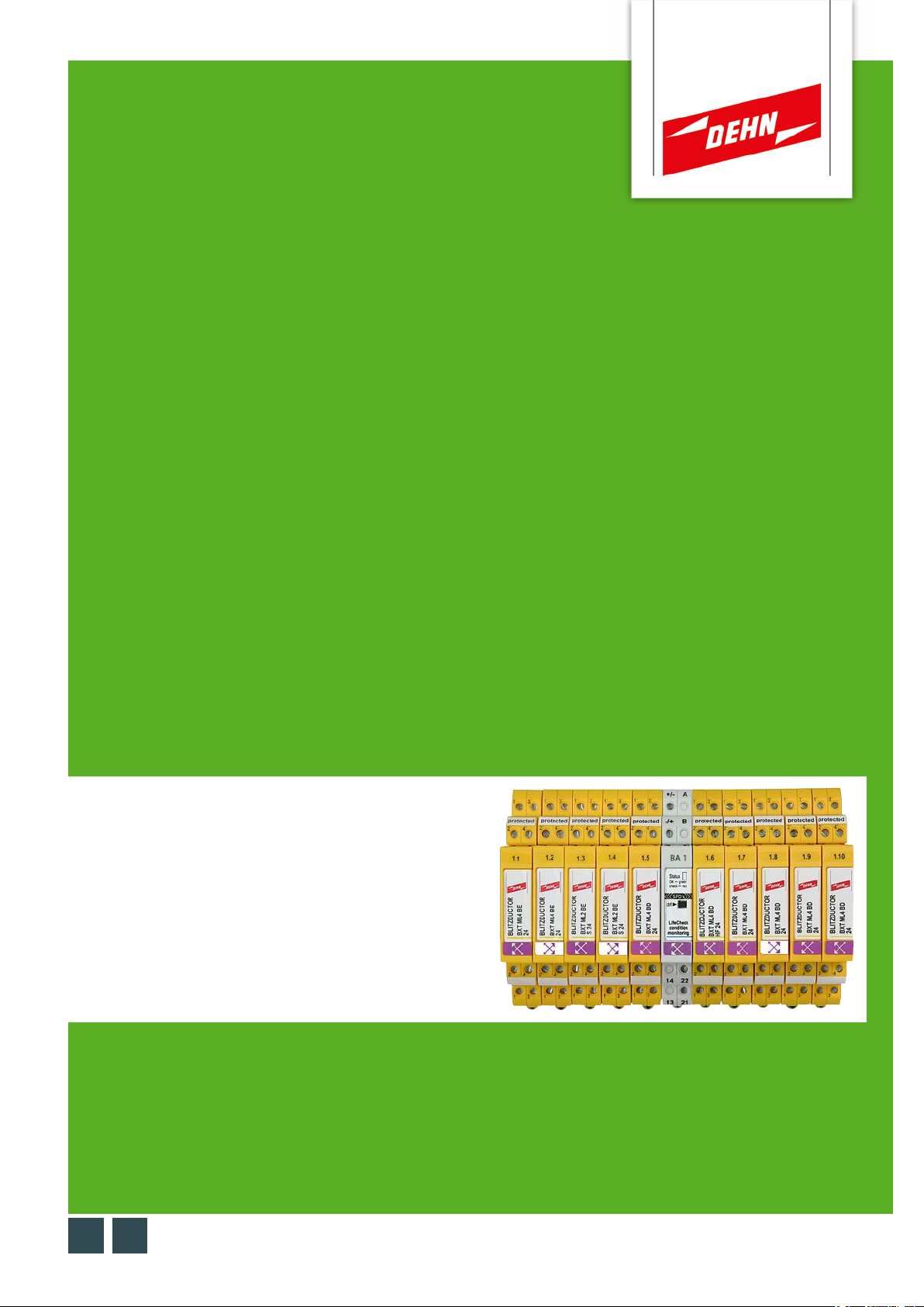
Überspannungsschutz
Kurzanleitung
Prüfgerät DEHNrecord DRC SCM XT
DE GB
BA 1
© COPYRIGHT 2019 DEHN SE + Co KGPublication No. 1809 / Update 07.19 Mat.-No. 3007884
Page 2
Kurzanleitung DEHNrecord DRC SCM XT
Inhaltsverzeichnis:
1. Lieferumfang 3
2. Generelle Hinweise 3
3. Installation 3
erdrahtung 4
4. V
5. Konfiguration 4
6. Betriebsablauf 5
7. Programmierung der SPDs mit SCM-Adresse und Positionsnummer 6
8. Ermittlung der zu tauschenden SPDs 8
9. Manueller Abbruch einer laufenden SPD-Prüfung 8
10. Technische Daten 9
11. Support 10
12. Sicherheitshinweise 10
13. Entsorgung 10
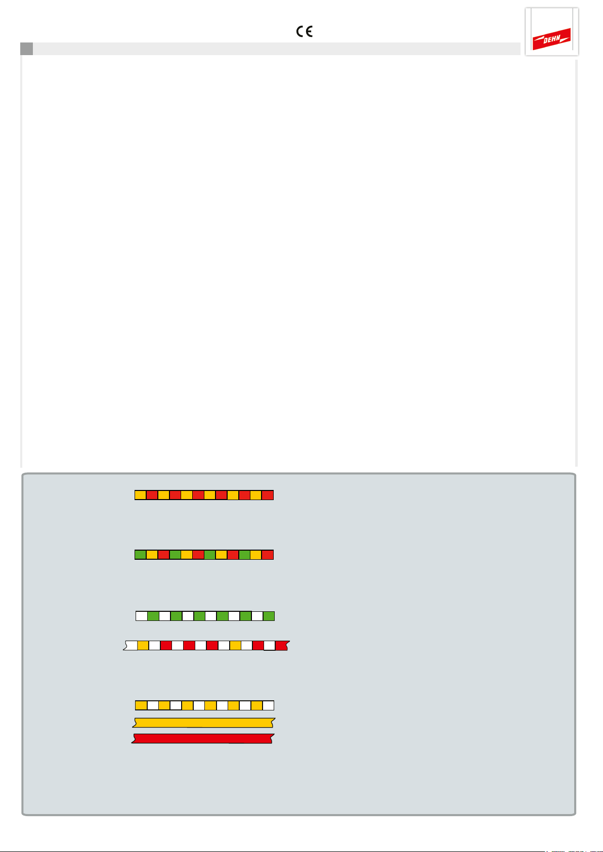
Statusanzeige DEHNrecord DRC SCM XT
Funktion LED-Signal Bedeutung ToDo
Anlaufsequenz ca. 5 sec bis zur ersten - - Überprüfung der SPDs
Fehler Konfiguration unzulässig Kontrolle DIP-Schalter
am DRC SCM XT
siehe Pkt. 5
Schutzgeräte alle in Ordnung - - -
Schutzgeräte SPD-Nr. des ersten zu min. 1 der überwachten
z.B. SPD-Nr. 3 tauschenden SPD SPD‘s tauschen
siehe Pkt. 8
Programmiermodus aktiv siehe Pkt. 7
SPD Prüfung
Resetmodus siehe ausführliche
Bedienungsanleitung
DEHNrecord
DRC SCM XT
Seite 2
Page 3
Kurzanleitung DEHNrecord DRC SCM XT
1. Lieferumfang
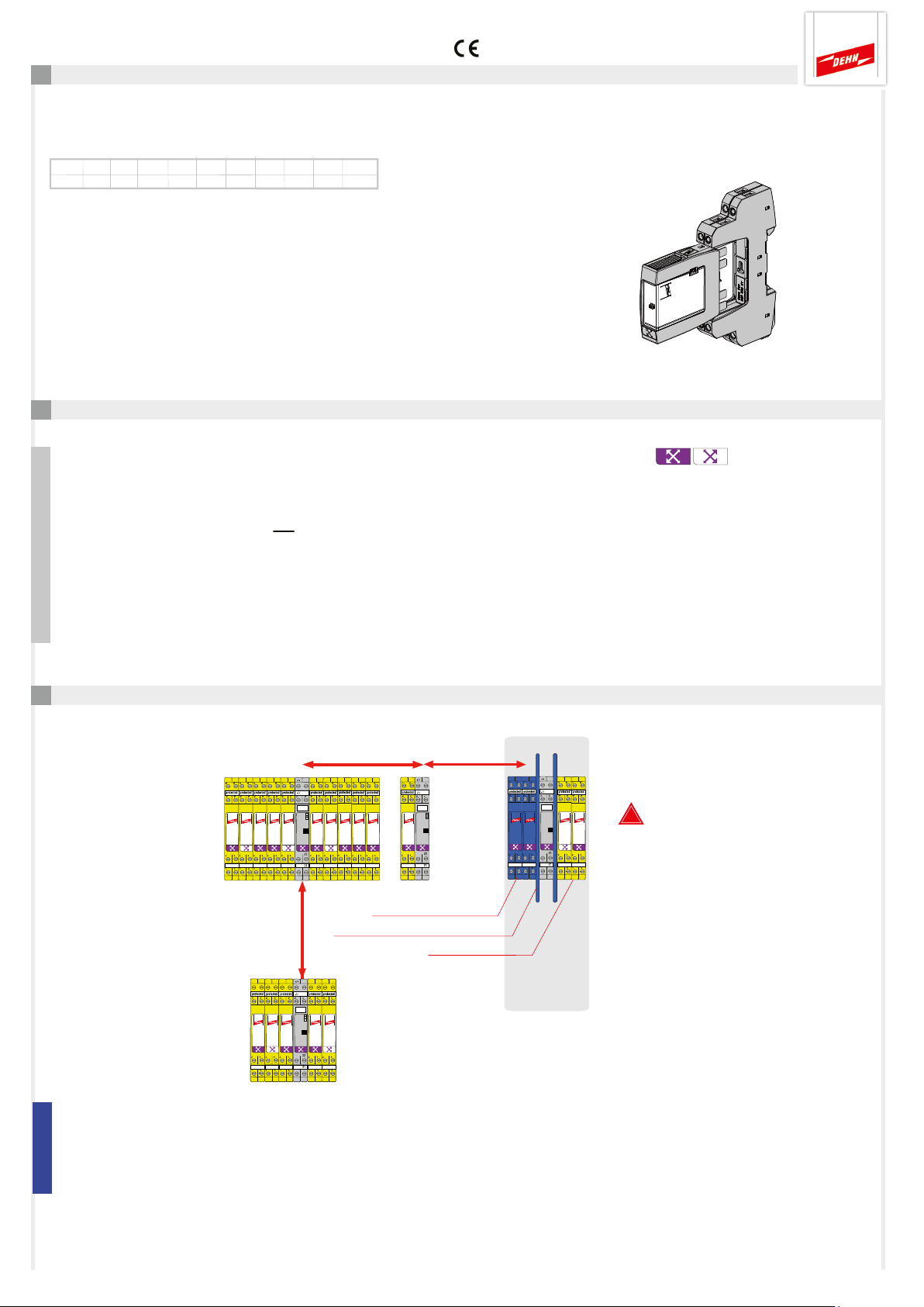
Beschriftungssystem
BA1 1.1 1.2 1.3 1.4 1.5 1.6 1.7 1.8 1.9 1.10
BA1 1.1 1.2 1.3 1.4 1.5 1.6 1.7 1.8 1.9 1.10
Ersatz-Zubehör BS BA1 BA15 BXT Art.-Nr. 920 398
Condition Monitoring
Modul
DEHNrecord,
DRC SCM XT, Art.-Nr. 910 696
Basisteil nur für:
DRC SCM XT
Ausführliche Bedienungsanleitung unter
www.dehn.de/download/ erhältlich! Siehe dazu auch Kapitel 11. Support.
2. Generelle Hinweise
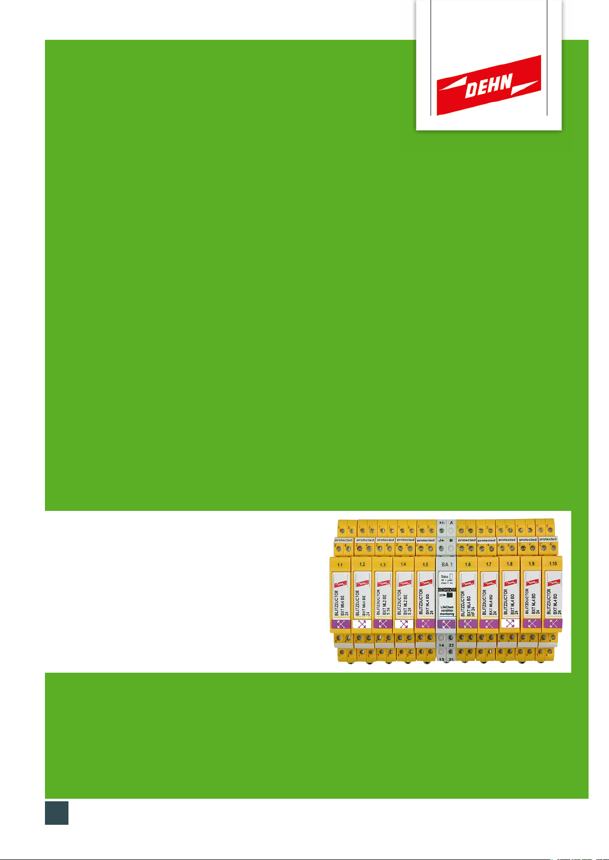
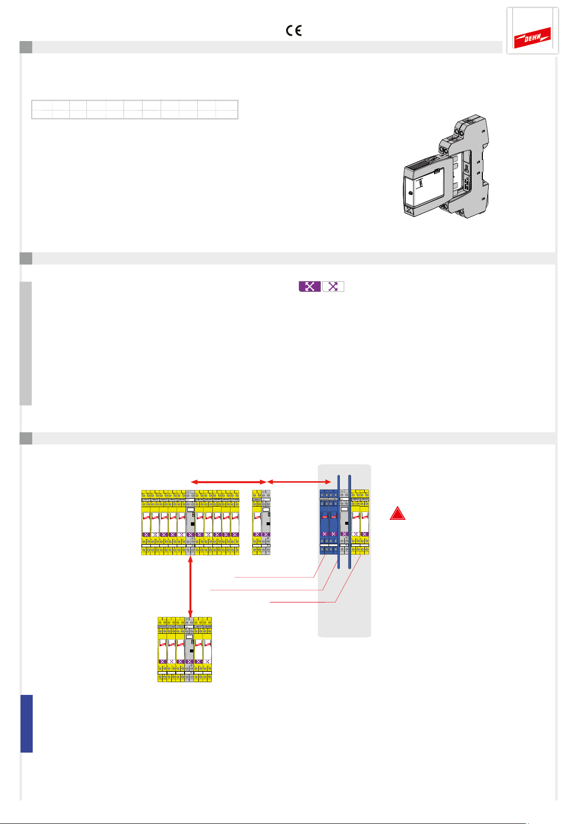
- Mit dem Gerät können 1...10 Schutzgeräte BLITZDUCTOR XT/XTU mit LifeCheck überwacht werden.
Die Anzahl der zu überwachenden SPDs ist am Gerät per DIP-Schalter einzustellen (siehe 5. Konfiguration).
- Die Anordnung des DRC SCM XT zu den überwachten SPDs hat grundsätzlich mittig zu erfolgen!
- Zu überwachende SPDs sind vor dem Einsatz mit einer Adresse zu programmieren (siehe Punkt 7).
Diese setzt sich aus der am DRC SCM XT voreingestellten SCM-Adresse (Adresse 1) und einer lfd. Positionsnummer
(Ableiternummer) zusammen.
- In unmittelbarer Nähe zum DRC SCM XT dürfen keine unprogrammierten SPDs liegen oder positioniert werden.
- Getaktete elektronische Geräte (z.B. elektronische Schaltnetzteile, Frequenzumrichter, uä.) sollten mit einem
Mindestabstand von 50 cm zum nächsten DRC SCM XT betrieben werden.
3. Installation
min. 50 cm
min. 50 cm
!
Beim Einsatz mehrerer
DRC SCM XT in einer Anlage
ist auf einen Mindestabstand
von min. 50 cm zwischen den
DEHNrecord DRC SCM XT-
BLITZDUCTOR XT Ex (i)
min. 50 cm
Ex i-Trennwand TW DRC MCM EX
BLITZDUCTOR XT
Schutzbeschaltung
eigensicherer
Stromkreise
Hinweis für den Betrieb in Verbindung mit Ex (i)-Kreisen:
Besondere Einbaubedingungen beachten, beim Einsatz des DEHNrecord DRC SCM XT in Verbindung mit BLITZDUCTOR XT
und XT Ex (i) für eigensichere Stromkreise. (siehe Fig. 2.1 sowie Einbauanleitung "Ex i-Trennwand TW DRC MCM EX",
Publication 1705). Bei Einsatz der Trennwand in Verbindung mit eigensicheren Stromkreisen ist ein Platzbedarf von min. 14 cm
zu berücksichtigen (z.B. Abstand Kabelkanäle min. 14 cm, Hutschiene mittig angeordnet).
Modulen zu achten!
Seite 3
Page 4
Kurzanleitung DEHNrecord DRC SCM XT
4. Verdrahtung
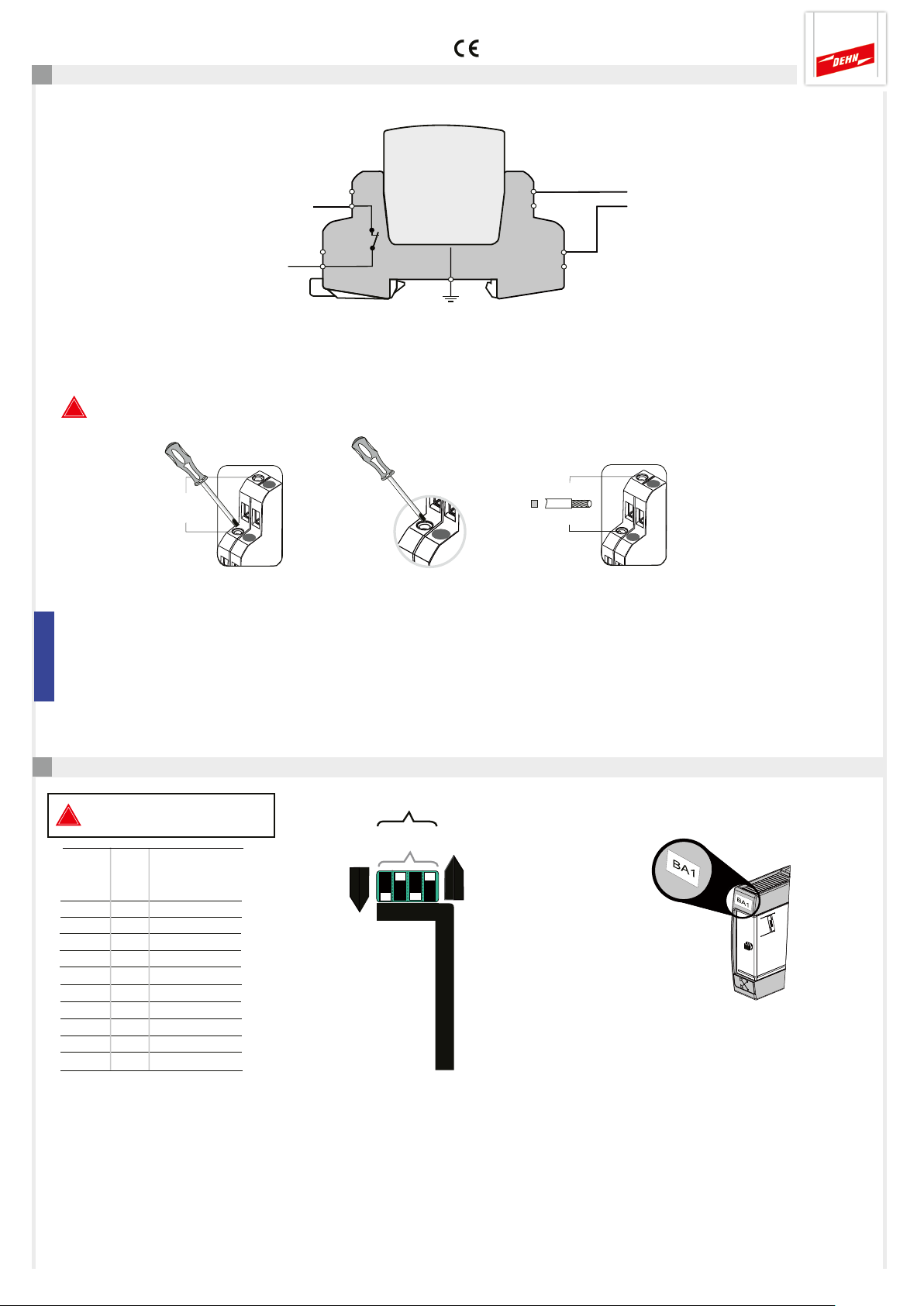
Fernmeldekontakt (FM)
galvanisch getrennter
Schaltkontakt im
Überwachungsmodul
DRC SCM XT integriert.
max. 350 V dc / 120 mA
250 V ac / 70 mA
Pin: 21-22 Öffner (nc)
*) Darstellung des Schaltkontakts im Normalzustand (alle überwachten SPD
sind OK) bei angelegter Versorgungsspannung und gestecktem DRC SCM XT.
!
Beachten Sie die technischen Daten des FM-Kontakts (siehe auch Punkt 10)!
22
*)
21
-/+ d.c.
+/- d.c.
Spannungsversorgung
U
18...48 VDC; max. 100 mA
N
Pin: +/-; -/+
Empfehlung DEHN:
Netzteil
PSU DC24 30W (Art.-Nr. 910 499)
max. 0,4 Nm
3,5 in-Ibs
size 0
max. 2,5 mm²
AWG 14
Hinweis für den Betrieb in Verbindung mit Ex (i)-Kreisen:
Aderleitungen eigensicherer und nicht eigensicherer Stromkreise, die in demselben Leitungsbündel- oder Kabelkanal geführt
werden, müssen nach EN 60079-14 durch eine Isolierstoff-Zwischenlage oder eine geerdete Metall-Zwischenlage getrennt sein.
Bei Verwendung von ummantelten Aderleitungen oder Leitungsschirmen für eigensichere oder nicht eigensichere Stromkreise
ist eine Trennung nicht erforderlich.
5. Konfiguration
Die Konfiguration muss bei
!
gezogenem Modul erfolgen!
Dezimal Dual-Code
Wertigkeit
8 4 2 1
1 ⇔ 0 0 0 1
2 ⇔ 0 0 1 0
3 ⇔ 0 0 1 1
4 ⇔ 0 1 0 0
5 ⇔ 0 1 0 1
6 ⇔ 0 1 1 0
7 ⇔ 0 1 1 1
8 ⇔ 1 0 0 0
9 ⇔ 1 0 0 1
1 0 ⇔ 1 0 1 0
Dezimal
Dual
DIP switch
0 = Off
1 = On
10*
1 0 1 0
On
8 4 2 1
Anzahl der zu
überwachenden SPDs
einstellen (max. 10)
Off
*) Beispiel
No. of monitored SPDs
Bezeichnungsschild für voreingestellte
SCM-Adresse (BA1) anbringen.
DEHNrecord
DRC SCM XT
Seite 4
Page 5
Kurzanleitung DEHNrecord DRC SCM XT
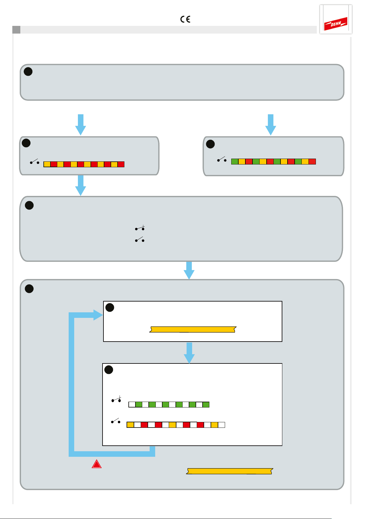
6. Betriebsablauf
Hinweis: Zu überwachende SPDs sind vor dem Einsatz mit einer Adresse zu programmieren (siehe Punkt 7).
1a
1
2
Anlauf
Prüfung der Konfiguration (DIP-Schalter siehe Punkt 5)
FM
21 22
Konfiguration OK
Startsequenz (5 Sek.)
LED
1b
Konfiguration nicht OK
Fehlerhafte Konfiguration
FM
LED
21 22
⇒ Konfiguration siehe Punkt 5
DRC SCM XT lädt automatisch den letzten gültigen Überwachungsstatus
Überwachungsstatus FM
alle SPD OK
min. ein SPD tauschen
21 22
21 22
Hinweis: Überwachungsstatus im Auslieferungszustand: alle SPD tauschen
3
DRC SCM XT startet automatisch den Prüfzyklus
3a
Überprüfung der zugeordneten SPDs
LED
3b
Ausgabe des ermittelten Überwachungsstatus
LED
FM
21 22
21 22
Hinweis:
!
Während einer lfd. Überprüfung (LED ) kann die Prüfung
durch Tastenbetätigung abgebrochen werden (siehe auch Punkt 9)!
z.B. SPD Nr. 2
Statusanzeige
oder
3 Min.
1 Min.
Status
OK
LifeCheck defekt,
SPD tauschen
Seite 5
Page 6
Kurzanleitung DEHNrecord DRC SCM XT
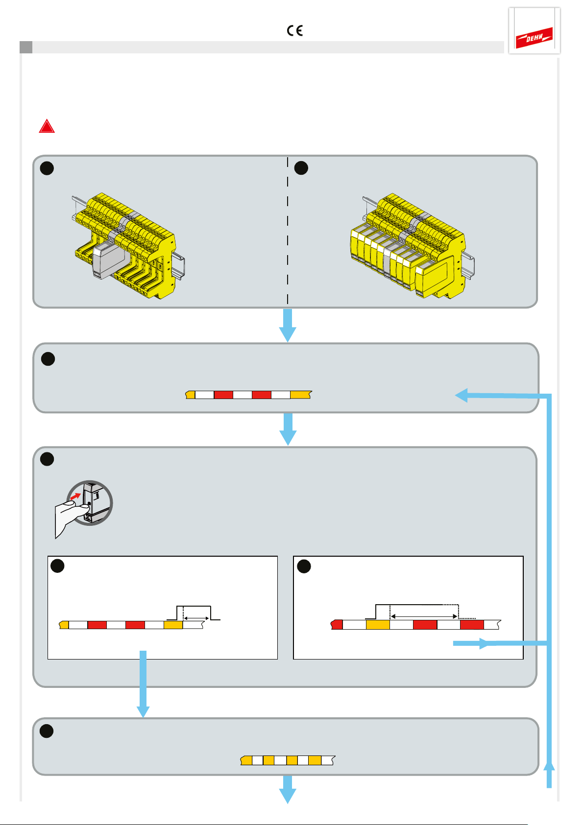
7. Programmierung der Ableiter-Adresse (SCM-Adresse und Positionsnummer)
Die Programmierung der SPDs erfolgt über den SHOW-Modus des DRC SCM XT.
Dieser wird automatisch ausgeführt, wenn während einer Überprüfung zu tauschende SPDs ermittelt wurden,
in dem die Nummer des ersten zu tauschenden SPDs über die LED ausgegeben wird. (Anzahl rot-Blinkimpulse)
!
Hinweis: eine laufende LifeCheck-Überprüfung kann manuell durch Tastendruck abgebrochen werden
(siehe auch 9. Manueller Abbruch einer laufenden Prüfung).
1a
Ausgangszustand bei Inbetriebnahme
2
Anzahl der roten Blinksignale entspricht der Nummer des zu programmierenden/tauschenden SPDs
1b
Im Wartungsfall defektes SPD entfernen
SHOW-Modus
z.B. SPD-Nr. 2
3
Taste betätigen
Die Taste wird während der Orangephase des Blinksignals gedrückt und nach Erlöschen der
LED losgelassen.
Hinweis: wird innerhalb 1 Min. die Taste nicht gedrückt, wird der SHOW-Modus verlassen
push ctrl
3a
Kurze Betätigung
Zum Programmieren Taste ca. 1-2 Sek. gedrückt
halten
⇒ Programmier-Modus aktiviert
4
und der Überwachungszyklus startet erneut.
1-2 Sek.
Lange Betätigung
3b
Um zum nächsten SPD zu blättern, Taste >5 Sek.
gedrückt halten
Tastenbetätigung
⇒ Nächstes SPD wird angezeigt
Programmier-Modus aktiviert
LED blinkt orange
> 5 sek.
Tastenbetätigung
Seite 6
Page 7
Kurzanleitung DEHNrecord DRC SCM XT
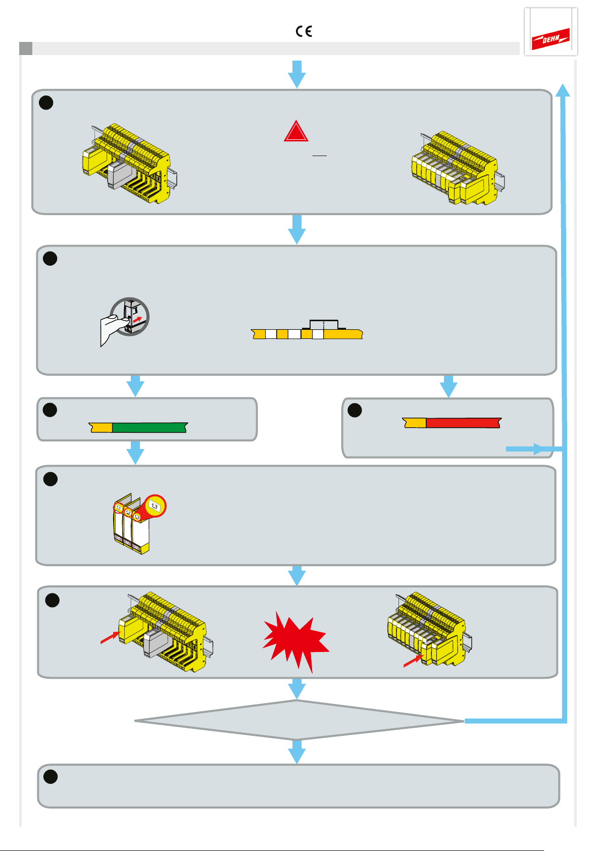
Fortsetzung von 7.
5
Inbetriebnahme
Ein nicht programmiertes SPD einsetzen
Wartungsfall
!
Immer nur ein
unprogrammiertes SPD zum
Programmieren einstecken!
Nicht ganz eindrücken!
siehe Bilder
6
Programmierung startet durch Betätigung der Ctrl-Taste bis LED-Anzeige
push ctrl
Programmierung läuft ... Ergebnis abwarten!
Programmierung starten
oranges Dauerlicht zeigt
7a
Programmierung erfolgreich
3 Sek.
Programmierung fehlgeschlagen
7b
3 Sek.
⇒ SPD-Nr. wird nochmal angezeigt
(für erneuten Programmierversuch)
8
Bezeichnungsschild für programmierte Ableiter-Adresse
9
Eindrücken
SPD beschriften
(SCM-Adresse•Positionsnummer) anbringen!
SPD in Basisteil einrasten
klick
Eindrücken
Seite 7
10
Ja
Sind weitere SPDs zu programmieren?
Nein
Ende der Programmierung
Der Show-Modus wird automatisch verlassen, ein neuer Prüfzyklus wird gestartet
automatisch Anzeige
der nächsten SPD-Nr.
Page 8
Kurzanleitung DEHNrecord DRC SCM XT
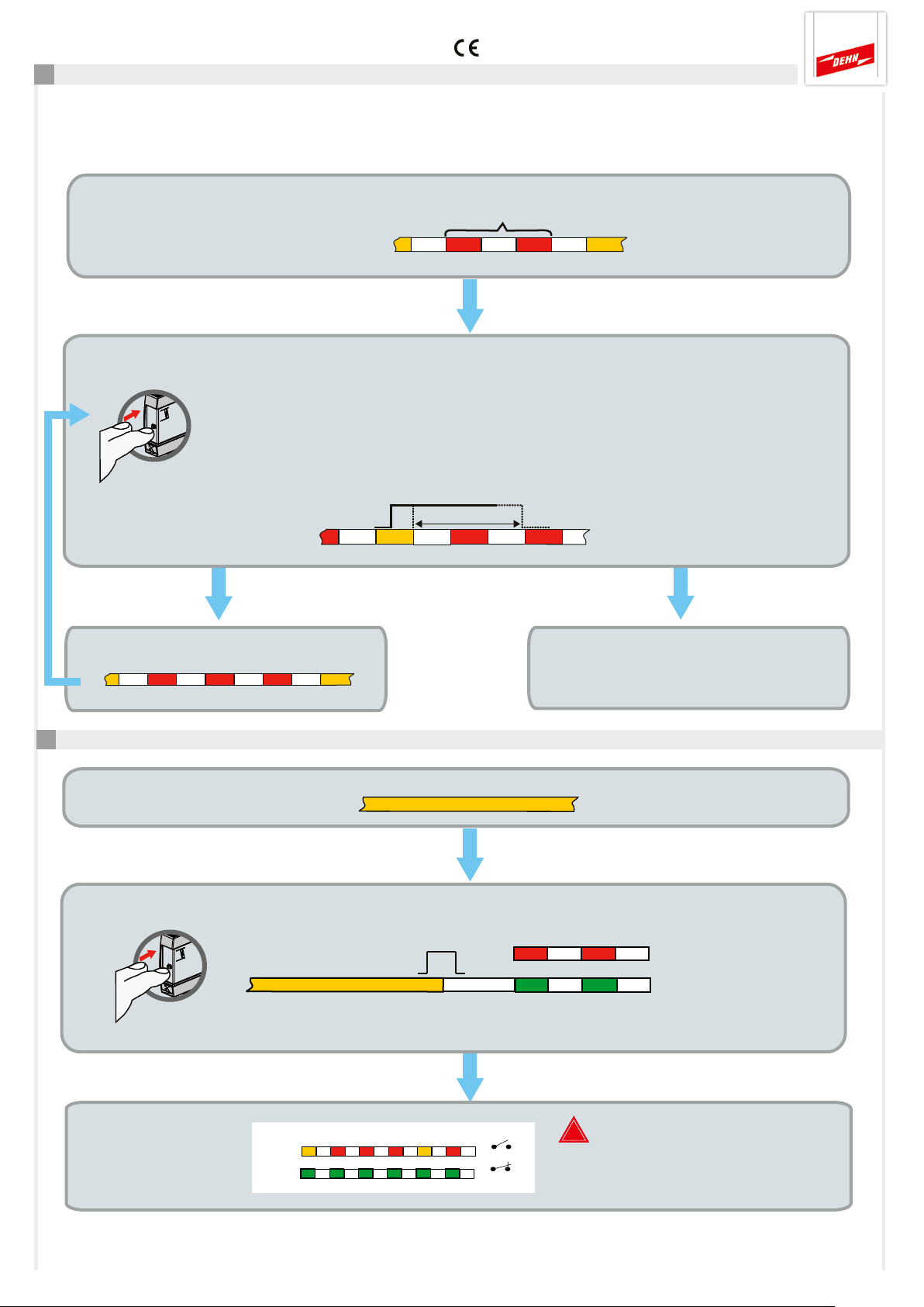
8. Ermittlung zu tauschender SPDs über SHOW-Modus am DRC SCM XT
Wurde während eines Prüfzyklus der Überwachungsstatus „SPD tauschen“ ermittelt, wird der SHOW-Modus
automatisch ausgeführt.
SHOW-Modus
LED-Anzeige des
ersten zu tauschenden SPDs
Anzahl = SPD-Nr. des zu tauschenden Schutzgerätes (z.B. Nr. 2)
Taste betätigen (lange Betätigung)
Die Taste wird während der Orangephase des Blinksignals gedrückt und nach Erlöschen
der LED nach >5 Sek. losgelassen.
push ctrl
Hinweis: wird innerhalb 1 Min. die Taste nicht gedrückt, wird der SHOW-Modus verlassen
und der Überwachungszyklus startet erneut.
LED-Anzeige des
nächsten zu tauschenden SPDs (z.B. Nr. 3)
SPD-Nr.
SPD-Nr.
> 5 Sek.
1 Minute
Tastenbetätigung
Kein weiteres zu tauschendes SPD vorhanden.
Ende des SHOW-Modus, ein neuer Prüfzyklus
wird automatsisch gestartet.
9. Manueller Abbruch einer laufenden SPD-Prüfung
Prüfzyklus läuft
LED
Taste betätigen
LED
push ctrl
⇒ Taste betätigen bis LED erlischt, letzter gültiger Status wird angezeigt
Anzeige letzter
gültiger, vollständig
ermittelter Status
LED
LED
Prüfzyklus abbrechen
letzter gültiger Status
oder
2 Sek.
FM
21 22
21 22
!
Der während einer abgebrochenen
Prüfung bereits ermittelte Teilstatus
bleibt unberücksichtigt!
Seite 8
Page 9
Kurzanleitung DEHNrecord DRC SCM XT
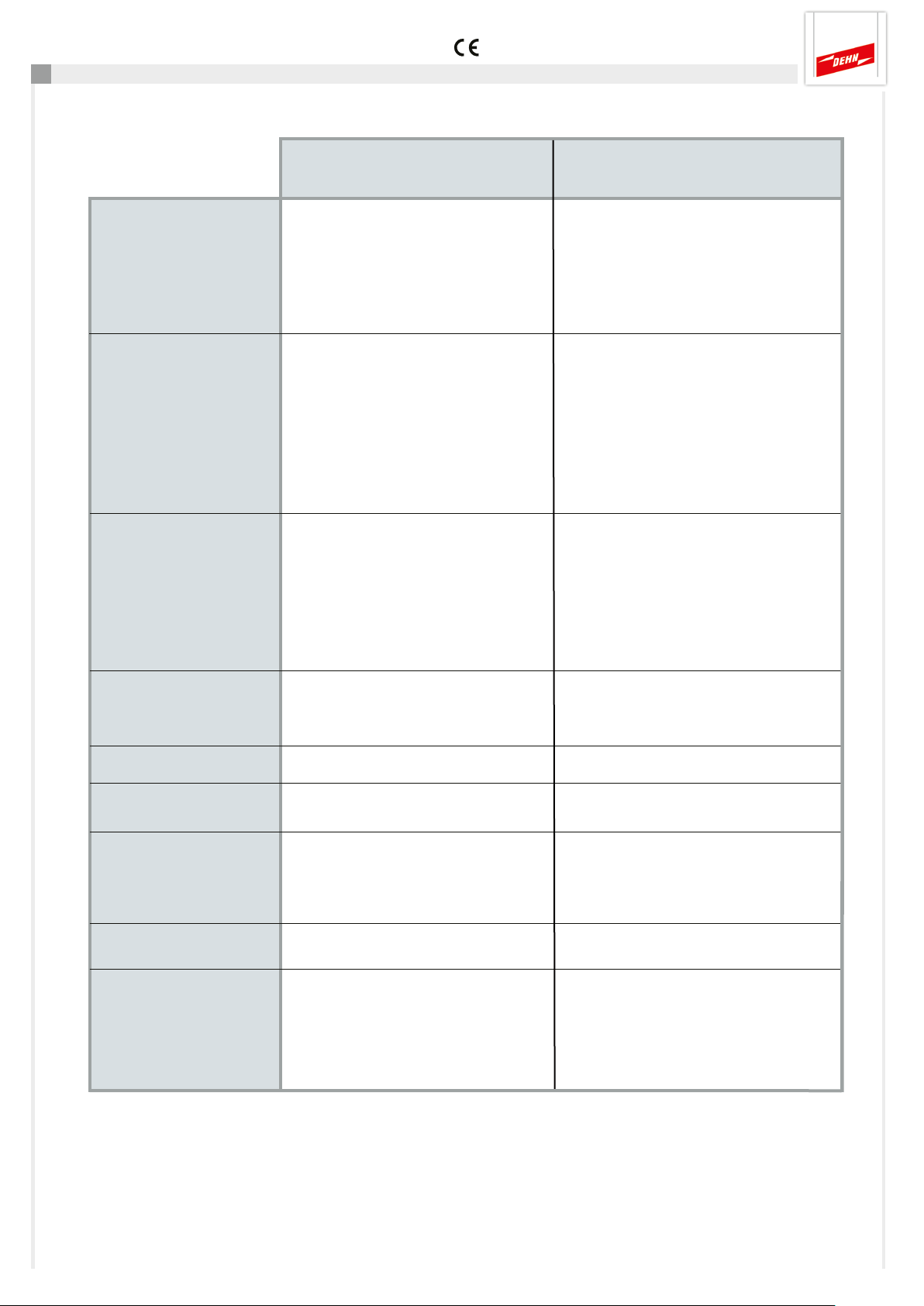
10. Technische Daten
Technische Parameter DRC SCM XT
Stromversorgung
Fernmeldekontakt
(FM)
Umgebungsbedingungen
Montage
Klemmenbezeichnung Pin +/-, -/+
Nennspannung (Bereich) U
Nennstromaufnahme I
Isolation keine
Polyswitch-Sicherung 0,3 A, 60 V / I
Klemmenbezeichnung am Basisteil Pin 21,22 (Öffner, nc)
Schaltspg. / Strom 250 V a.c. / 70 mA
350 V d.c. / 120 mA
max. 300 mW
Isolation 1500 V a.c.
EIN-Widerstand /AUS-Leckstrom typ. 17 Ω (max. 25 Ω) / max. 1 µA
Betriebstemperaturbereich
Standard - 20... + 60° C (1...10 SPD)
erweitert - 40... + 80° C (1...8 SPD)
Einsatzhöhe bis 2000 m, wenn: U
über 2000 m, wenn: U
auf 35 mm Hutschiene nach
EN 60715, metallisch
24 (18...48) V d.c.
N
80 (100...60) mA
N
> 33 V
FM
< 33 V
FM
max: 10 A
BR
eff
eff
bzw. 70 V d.c.
bzw. 70 V d.c.
Gehäusewerkstoff
Schutzart
Abmessungen
Gewicht
Normen
Polyamid PA 6.6 (RAL 7035)
IP 20
Breite 12 mm (2/3 TE, DIN 43880)
Tiefe ohne Anschlüsse 90 mm
Höhe über Hutschiene 66 mm
62 g
Sicherheit EN 61010-1 (elektr. Messgeräte)
EMV EN 61000-6-2 (Störfestigkeit)
EN 61000-6-3 (Störaussendung)
ETSI EN 300330-1 (ERM)
Seite 9
Page 10
Kurzanleitung DEHNrecord DRC SCM XT
11. Support
Weiterführende Informationen und Hinweise:
- Ausführliche Bedienungsanleitung, DEHNrecord DRC SCM XT
Diese steht unter: www.dehn.de/download/ im Bereich Mess- und Prüfsysteme als Download zur Verfügung.
Nach dem Login bzw. der Registrierung (für Neukunden) kann aus dem Verzeichnis "DEHNrecord - DRC SCM XT"
die ausführliche Bedienungsanleitung heruntergeladen werden.
12. Sicherheitshinweise
Der Anschluss und die Montage des Gerätes darf nur durch eine Elektrofachkraft erfolgen. Die nationalen Vorschriften
und Sicherheitsbestimmungen sind zu beachten.
Vor der Montage ist das Gerät auf äußere Beschädigung zu kontrollieren.
Sollte eine Beschädigung oder ein sonstiger Mangel festgestellt werden, darf das Gerät nicht montiert werden.
Der Einsatz des Gerätes ist nur im Rahmen der in den Einbauanleitungen genannten und gezeigten Bedingungen
zulässig. Bei Belastungen, die über den ausgewiesenen Werten liegen, können das Gerät sowie die daran
angeschlossenen elektrischen Betriebsmittel zerstört werden.
Eingriffe und Veränderungen am Gerät führen zum Erlöschen des Gewährleistungsanspruches.
13. Entsorgung
Das Gerät darf nicht über den Hausmüll entsorgt werden!
Weiterführende Informationen entnehmen Sie unserer Homepage:
www.dehn.de
Seite 10
Page 11

Kurzanleitung DEHNrecord DRC SCM XT
Notizen
Seite 11
Page 12

Überspannungsschutz DEHN SE + Co KG Hans-Dehn-Str. 1 Tel. +49 9181 906-0
Blitzschutz/Erdung Postfach 1640 www.dehn.de
Arbeitsschutz 92306 Neumarkt
DEHN schützt. Deutschland
Page 13
Surge Protection
Quick Start Guide
DEHNrecord DRC SCM XT
Test Device
GB
BA 1
© COPYRIGHT 2019 DEHN SE + Co KGPublication No. 1809 / Update 07.19 Mat.-No. 3007884
Page 14
Quick Guide DEHNrecord DRC SCM XT
Contents:
1. Scope of delivery 3
2. General notes 3
3. Installation 3
4. Wiring 4
5. Configuration 4
6. Operating procedure 5
7. Programming the SPD address (SCM address and position No.) 6
8. Determination of SPDs to be replaced 8
9. Manual abort during an ongoing SPD test 8
10. Technical data 9
11. Support 10
12. Safety instructions 10
13. Disposal 10
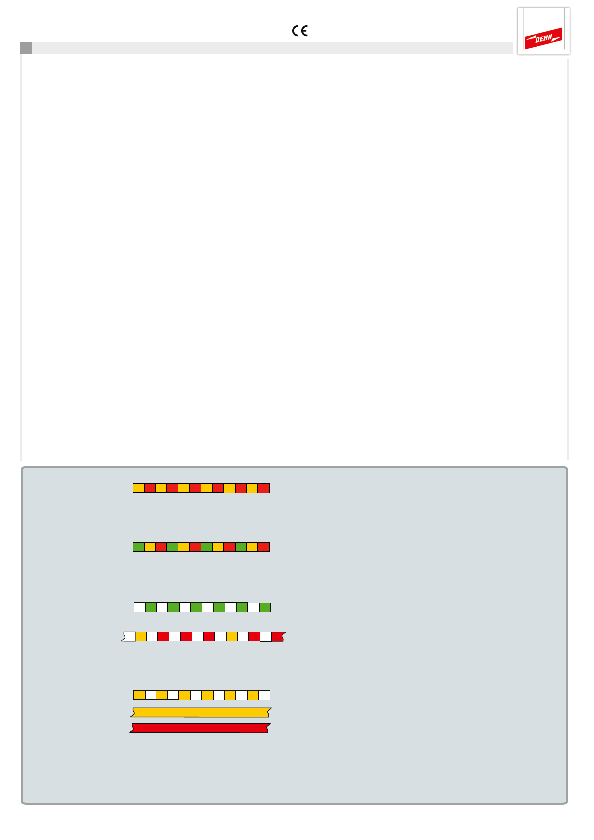
DEHNrecord DRC SCM XT status display
Function LED signal Meaning To do
Boot up sequence Approximately 5 sec. until - - the SPDs are tested
Fault Impermissible configuration Check DIP switch at
the DRC SCM XT
(see 5.)
Protective devices OK - - -
Protective devices SPD No. of the first SPD Replace at least one
For example SPD No. 3 to be replaced of the monitored
SPDs (see 8.)
Programming mode active See 7.
SPD testing
Reset mode See detailed operating
manual of
DEHNrecord
DRC SCM XT
Page 2
Page 15
Quick Guide DEHNrecord DRC SCM XT
1. Scope of delivery
Labelling system
BA1 1.1 1.2 1.3 1.4 1.5 1.6 1.7 1.8 1.9 1.10
BA1 1.1 1.2 1.3 1.4 1.5 1.6 1.7 1.8 1.9 1.10
Accessory, BS BA1 BA15 BXT Part No. 920 398
condition monitoring module,
DEHNrecord
DRC SCM XT
Part No. 910 696
Base part only for
DRC SCM XT
Detailed operating instructions are available at
www.dehn.de/download/ (see also 11. Support)!
2. General notes
- The device allows to monitor 1 to 10 LifeCheck-equipped BLITZDUCTOR XT/XTU surge protective
devices. The number of SPDs to be monitored must be selected via the DIP switch (see 5. Configuration).
- The DRC SCM XT test device must be positioned in the centre of the SPDs to be monitored!
- SPDs to be monitored must be programmed with an address prior to use (see 7.).
This address consists of the SCM address (address 1) preset at the DRC SCM XT and a consecutive position number
(SPD number).
- Unprogrammed SPDs must not be located or positioned in the vicinity of the DRC SCM XT test device.
- Clocked electronic devices (e.g. electronic switching power supplies, frequency converters etc.) shall be operated
with a minimum distance of 50 cm to the next DRC SCM XT.
3. Installation
min. 50 cm
min. 50 cm
!
If several DRC SCM XT
SCM XT are installed in one
system, keep a minimum
distance of at least 50 cm
between the DRC SCM XT
BLITZDUCTOR XT Ex (i)
min. 50 cm
Ex i partition of type TW DRC MCM EX
BLITZDUCTOR XT
Protective circuit of
intrinsically safe
measuring circuits
Note on use in Ex(i) circuits:
Certain requirements must be fulfilled when using DRC SCM XT in conjunction with BLITZDUCTOR XT and XT Ex (i) for
intrinsically safe circuits (see Fig. 2.1 and installation instructions “Ex i partition TW DRC MCM EX”, publication 1705). When
installing the partition in intrinsically safe circuits, a space requirement of at least 14 cm must be observed (e.g. distance from
cable ducts at least 14 cm, DIN rail arranged in the centre).
modules!
Page 3
Page 16
Quick Guide DEHNrecord DRC SCM XT
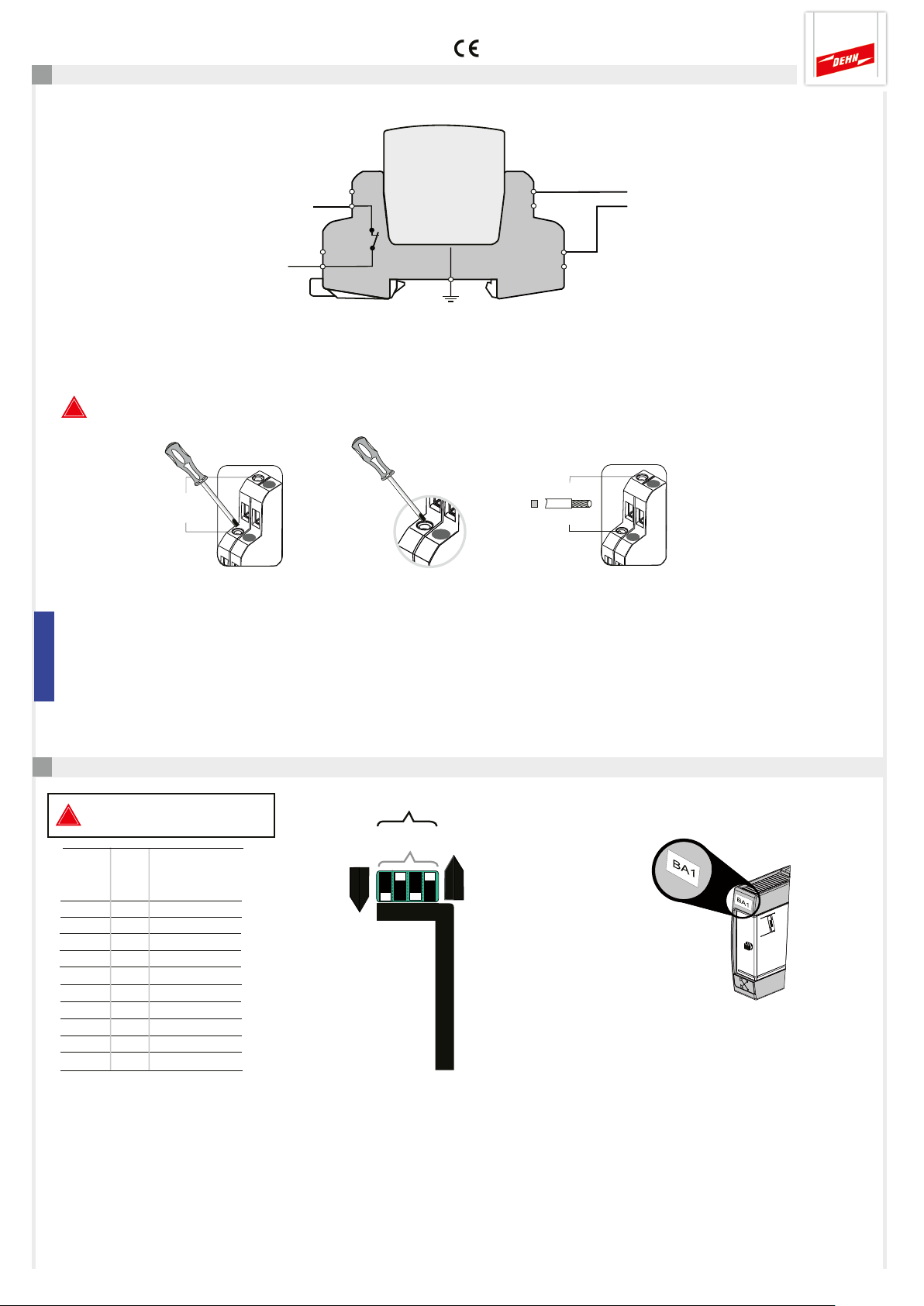
4. Wiring
Remote signalling contact (FM)
Galvanically isolated switch contact
integrated in the DRC SCM XT
monitoring module
max. 350 V d.c. / 120 mA
250 V a.c. / 70 mA
Pin: 21-22 break contact (nc)
22
*)
21
*) switch contact shown in its normal state (all monitored SPDs are OK), that is supply
voltage is applied and the DRC SCM XT module is plugged in.
!
Observe the technical data of the remote signalling contact (see also 10.)!
-/+ d.c.
+/- d.c.
Voltage supply
UN 18...48 V d.c.; max. 100 mA
Pin: +/-; -/+
Recommendation DEHN:
power sypply unit
PSU DC24 30W (Part No. 910 499)
max. 0.4 Nm
3.5 in-Ibs
size 0
max. 2.5 mm²
AWG 14
Note on use in Ex (i) circuits:
Single-core, non-sheathed cables of intrinsically and non-intrinsically safe circuits routed together in conductor bundles or cable
ducts must be separated by an intermediate layer of insulating material or an earthed metal intermediate layer in accordance
with EN 60079-14. Separation is not required if sheathed cables or cable shields are used in intrinsically and non-intrinsically
safe circuits.
5. Configuration
The module must be
!
removed for configuration!
Decimal Binary code
Value
8 4 2 1
1 ⇔ 0 0 0 1
2 ⇔ 0 0 1 0
3 ⇔ 0 0 1 1
4 ⇔ 0 1 0 0
5 ⇔ 0 1 0 1
6 ⇔ 0 1 1 0
7 ⇔ 0 1 1 1
8 ⇔ 1 0 0 0
9 ⇔ 1 0 0 1
1 0 ⇔ 1 0 1 0
DIP switch
0 = Off
1 = On
Decimal
Binary
10*
1 0 1 0
On
8 4 2 1
Select number of
SPDs to be monitored
(max. 10)
Off
*) example
No. of monitored SPDs
Attach label for preset
SCM address (BA1)
DEHNrecord
DRC SCM XT
Page 4
Page 17
Quick Guide DEHNrecord DRC SCM XT
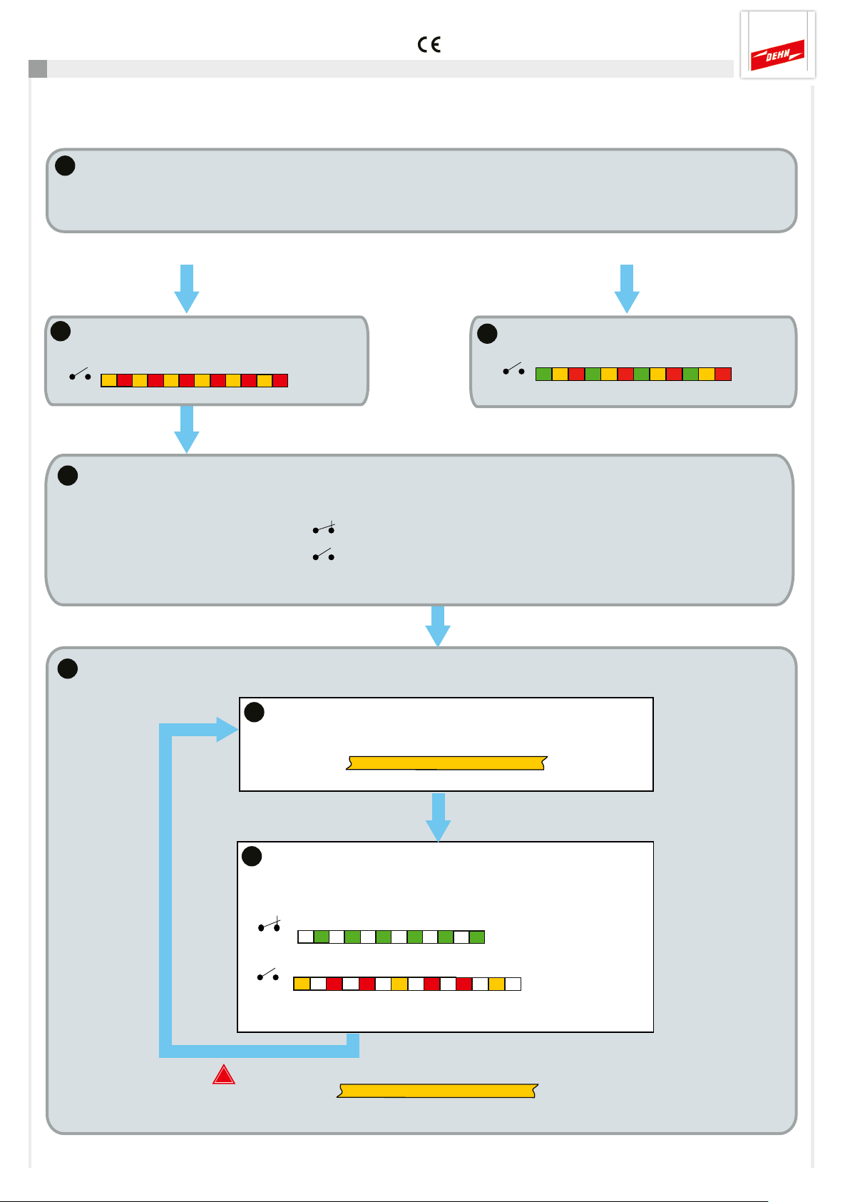
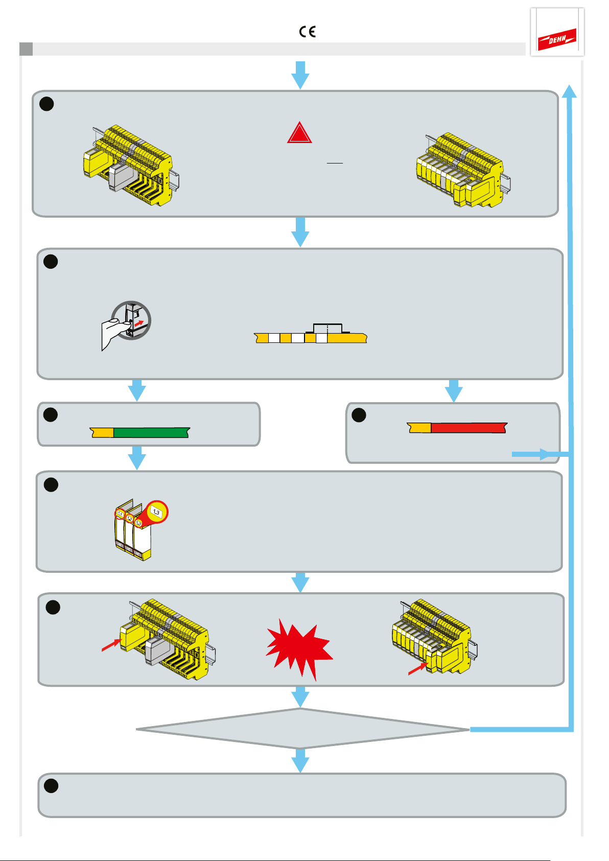
6. Operating procedure
Note: Programme an address on the SPDs to be monitored before use (see 7).
1a
1
2
Boot up
Checking the configuration (DIP switch see 5.)
Configuration OK
Start sequence (5 sec.)
LED
FM
21 22
1b
Configuration not OK
LED
FM
21 22
⇒ Configuration see 5.
DRC SCM XT automatically loads the last valid monitoring status
Monitoring status FM
All SPDs OK
Replace at least one SPD
21 22
21 22
Note: When delivered, the monitoring status is set to “Replace all SPDs”
Configuration faulty
3
DRC SCM XT automatically starts the test cycle
3a
Checking the assigned SPDs
LED
3b
LED
FM
21 22
21 22
Note:
!
Ongoing tests (LED ) can be aborted by pressing the ctrl
button (see 9.)!
e.g. SPD No. 2
Status display
Display of the monitoring status
3 min.
or
1 min.
Status
OK
LifeCheck faulty,
replace SPD
Page 5
Page 18
Quick Guide DEHNrecord DRC SCM XT
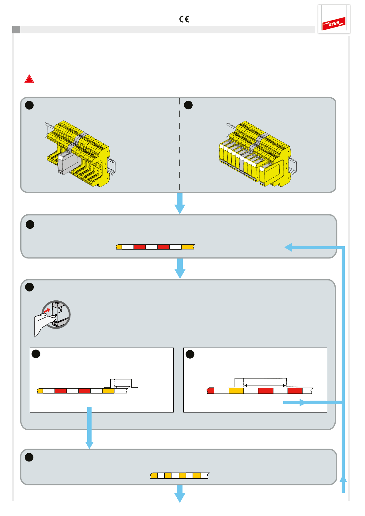
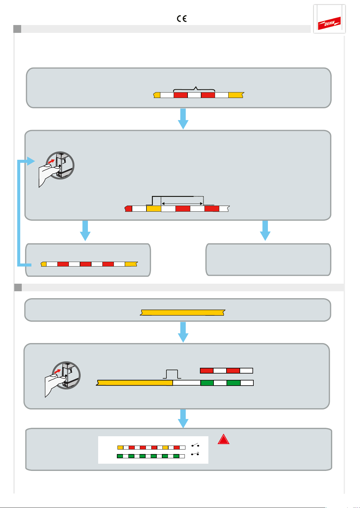
7. Programming the SPD address (SCM address and position No.)
SPDs are programmed via the SHOW mode of the DRC SCM XT.
This mode is automatically started if SPDs to be replaced are detected during a test. The number of the first SPD to be
replaced is indicated by the LED (number of red flashing pulses).
!
Note: An ongoing LifeCheck test can be aborted manually by pressing the ctrl button
(see also 9. Manual abort during an ongoing test).
1a
1b
Initial state when commissioning Remove faulty SPD during maintenance work
2
SHOW mode
Number of red flashing pulses corresponds to the number of SPDs to be programmed/replaced.
e.g. SPD No. 2
3
Press button
Press the ctrl button when the LED flashes orange and release it after the LED goes out.
Note: If the button is not pressed within one minute, the SHOW mode is terminated and the
push ctrl
3a
Press short
Keep button pressed for about 1 to 2 seconds
for programming
⇒ Programming mode activated
4
monitoring cycle is restarted.
1-2 Sec.
3b
Press long
Press button for more than 5 seconds to jump
to the next SPD
Press button
⇒ Next SPD is shown
Programming mode activated
LED flashes orange
> 5 sec.
Press button
Page 6
Page 19
Quick Guide DEHNrecord DRC SCM XT
Continued from 7.
5
Commissioning
Insert an unprogrammed SPD
Maintenance work
!
Always insert only one
unprogrammed SPD for
programming! Do not snap it
in completely (see pictures)!
6
Press the ctrl button to start programming until the LED is continuously
push ctrl
Programming in progress … Wait for result!
Start programming
illuminated orange.
7a
Programming successful
3 sec.
7b
Programming failed
3 sec.
⇒ SPD No. is indicated again
(for new programming attempt)
8
Attach label for programmed SPD address
9
press in
Snap SPD into base part
Label SPD
(SCM address•position No.)!
click
press in
Page 7
10
Any other SPDs to be programmed?
Yes
No
End of programming
The SHOW mode is automatically terminated, a new test cycle is started.
Next SPD No. is
automatically shown
Page 20
Quick Guide DEHNrecord DRC SCM XT
8. Determination of SPDs to be replaced via the SHOW mode at the DRC SCM XT
If the “Replace SPD” monitoring status has been determined during a test cycle, the SHOW mode is
automatically started.
SHOW mode
LED indicates the first SPD
to be replaced
Number = SPD No. of the surge protective device to be replaced (e.g. No. 2)
Press ctrl button (press long)
Press the ctrl button when the LED flashes orange and release it after 5 sec. upon the LED
goes out.
push ctrl
Note: If the ctrl button is not pressed within one minute, the SHOW mode is terminated
and the monitoring cycle is restarted.
LED indicates the next SPD to be replaced
(e.g. No. 3)
SPD No.
SPD No.
> 5 sec.
1 minute
Press button
No other SPD must be replaced. SHOW mode
finished, a new test cycle is automatically
started.
9. Manual abort during an ongoing SPD test
Test cycle running
LED
push ctrl
⇒ Press the ctrl button until the LED goes out, the last valid status is indicated.
Last valid
status
indicated
LED
LED
LED
Press button
Abort test cycle
Last valid status
or
2 Sec.
FM
21 22
21 22
!
Partial statuses determined
during an aborted test
are not considered!
Page 8
Page 21
Quick Guide DEHNrecord DRC SCM XT
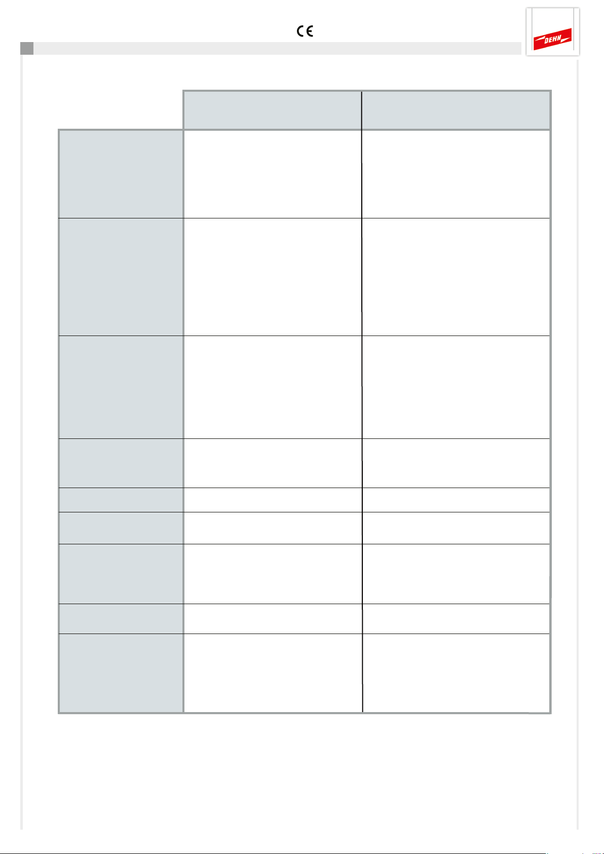
10. Technical data
Technical parameters DRC SCM XT
Power supply
Remote
signalling
contact
Ambient
conditions
Installation
Terminal designation Pin +/-, -/+
Nominal voltage (range) U
Nominal current consumption I
Insulation None
Polyswitch fuse 0.3 A, 60 V / I
Terminal designation at the base Pin 21,22 (break contact, nc)
part 250 V a.c. / 70 mA
Switching voltage/current 350 V d.c. / 120 mA
max. 300 mW
Insulation 1500 V a.c.
ON resistance/ OFF leakage current Typically 17 Ω (max. 25 Ω) / max. 1 µA
Operating temperature range
Standard -20... + 60° C (1...10 SPDs)
Extended -40... + 80° C (1...8 SPDs)
Altitude up to 2000 m, If: U
above 2000 m, If: U
on 35 mm DIN rails in accordance with
EN 60715, metallic
24 (18...48) V d.c.
N
80 (100...60) mA
N
> 33 V
FM
< 33 V
FM
max: 10 A
BR
to 70 V d.c.
eff
to 70 V d.c.
eff
Enclosure material
Degree of protection
Dimensions
Weight
Standards
Polyamide PA 6.6 (RAL 7035)
IP 20
Width 12 mm (2/3 modules, DIN 43880)
Depth without connections 90 mm
Height above DIN rail 66 mm
62 g
Safety EN 61010-1 (electrical equipment)
EMC EN 61000-6-2 (immunity)
EN 61000-6-3 (emissions)
ETSI EN 300330-1 (ERM)
Page 9
Page 22
Quick Guide DEHNrecord DRC SCM XT
11. Support
For additional information, please refer to our
- Detailed operating manual, DEHNrecord DRC SCM XT
This manual can be downloaded at www.dehn.de/download/ in the Measuring and Test Systems / Login section.
After login / registration (new customers), the detailed operating manual can be downloaded from the
“DEHNrecord - DRC SCM XT” directory.
12. Safety instructions
Only electrically skilled persons are allowed to connect and install the device. The national rules and safety regulations
must be observed.
Prior to installation, the device must be visually examined for signs of damage.
If the device has any damage or other defect, it must not be installed.
The device may only be used under the conditions shown and referred to in these installation instructions.
Loads above the values indicated can lead to the destruction of the device and the electrical equipment connected.
Do not attempt to tamper with or modify the device in any way as this will void warranty.
13. Disposal
The device should not be disposed of in the normal household waste.
For more Information please refer to our website:
www.dehn-international.com
Page 10
Page 23

Quick Guide DEHNrecord DRC SCM XT
Notes
Page 11
Page 24

Surge Protection DEHN SE + Co KG Hans-Dehn-Str. 1 Tel. +49 9181 906-0
Lightning Protection Postfach 1640 www.dehn-international.com
Safety Equipment 92306 Neumarkt
DEHN protects. Germany
 Loading...