

De Haardt Xtra., Xtra.Remote Kart & Track Control System Series Manual

Manual Xtra.Remote Kart &
Track Control System
1
Date : 22-02-2007
Version : 2.0
The information in this manual is subject to change without
notice. Any trademarks, trade names, service marks or
service names owned or registered by any other company
and used in this manual are property of their respective
companies.
All rights reserved.
De Haardt Electronic Engineering BV
Nijverheidsweg 19-b
6662 NG Elst (GLD)
The Netherlands
Tel: 0481 353202
Fax: 0481 353603
All products are designed as
supplement to make karting
safer, but
cannot replace safe track procedures. If
equipment fails, the normal operating procedure must still
be adequate to safely operate the track.
This guide has been written with great care. However, the
manufacturer cannot be held responsible, either for any
errors occurring in this publication or for their
consequences.

Manual Xtra.Remote Kart &
Track Control System
2
1 Index
1
Index ................................................................... 2
2 Safety summary .................................................... 4
3 Introduction .......................................................... 5
4 Installation ........................................................... 6
4.1 Xtra.Remote Control Unit ................................. 6
4.1.1 Placing the batteries ................................. 6
4.1.2 Connecting the adapter ............................. 8
4.1.3 Connecting the antenna ............................ 8
4.1.4 Connecting to a Personal Computer ............ 9
4.2 Xtra.Shutdown transponder.............................. 9
4.2.1 Assembly of the Xtra.Shutdown transponder..
.............................................................10
4.2.2 Electrical connection of the Xtra.Shutdown
transponder ............................................13
4.3 Xtra.Range Extender / Accesspoint ...................15
4.3.1 Mounting of the Xtra.Range Extender /
Accesspoint .............................................15
4.3.2 Electrical connections of the Xtra.Range
Extender / Accesspoint .............................18
4.4 Xtra.(warning) light control board ....................21
4.4.1 Mounting the Light control board ...............21
4.4.2 Wiring the light control board....................22
4.5 Xtra.Sector Control System .............................26
4.5.1 Electrical connection of the Xtra.Sector
Beacon ...................................................28
4.5.2 Mounting of the Xtra.Sector Sensor ...........29
4.5.3 Electrical connection Xtra.Sector Sensor .....30
5 Operating the equipment .......................................32
5.1 Basic operation of the Xtra.Remote Control .......32
5.1.1 Switching the Remote Control On/Off.........32
5.1.2 Adjusting the speed of kart(s)...................32
5.1.3 Adjusting the speed of an individual kart ....32
5.1.4 Adjusting the speed of a group of karts ......33

Manual Xtra.Remote Kart &
Track Control System
3
5.1.5 Adjust the speed of all karts at once ..........33
5.1.6 Adjusting the speed in multiple sectors ......33
5.1.7 Penalties ................................................34
5.1.8 Adjusting the speed in steps .....................34
5.1.9 Repeating last command ..........................35
5.1.10 Operating (race) lights .............................35
5.2 Menu functions ..............................................35
5.2.1 Menu->Remote->Track ............................36
5.2.2 Menu->Remote->Brightness .....................36
5.2.3 Menu->Remote->Backlight.......................36
5.2.4 Menu->Remote->Power Save ...................36
5.2.5 Menu->Remote->Penalty Time .................37
5.2.6 Menu->Remote->Power Info ....................37
5.2.7 Menu->Shutdown tp->Assign ...................37
5.2.8 Menu->Shutdown tp->Read timer .............38
5.2.9 Menu->Shutdown tp->Reset timer ............38
5.2.10 Menu->Shutdown tp->Read RPM...............38
5.2.11 Menu->Shutdown tp->RPM Limits .............38
5.2.12 Menu->RangeExtend->Track ....................39
5.2.13 Menu->RangeExtend->Link Check.............39
5.3 Configuration of the Xtra.Sector Beacon............40
5.3.1 Mode -> Sector number ...........................41
5.3.2 Mode -> Function number ........................42
5.3.3 Mode -> Address .....................................43
5.3.4 Mode -> Error .........................................43
5.4 Operating the Xtra.Sector Sensor .....................43
WEEE Legislation .........................................................45
6 Declaration of Conformity ......................................46
7 Technical specifications..........................................47
7.1 Xtra.Remote Control .......................................47
7.2 Xtra.Shutdown transponder.............................49
7.3 Xtra.Range extender / Access point ..................50
7.4 Light control board .........................................51
7.5 Xtra.Sector Beacon.........................................52
7.6 Xtra.Sector Sensor .........................................53
8 Warranty .............................................................54

Manual Xtra.Remote Kart &
Track Control System
4
2 Safety summary
To ensure thorough understanding of all functions and to
ensure efficient use of the system, please read this manual
carefully before using.
Please observe the following basics to prevent fire, burn,
electric shock, and personal injury:
• Electrical and mechanical installation and servicing is
only allowed by qualified personnel.
• Be sure to plug mains powered equipment in an
electrical outlet which has a safety ground terminal.
• Never use the equipment with the case open.
• Service and repairs are only allowed by qualified
technical engineers.
• Be sure to use fuses rated to the voltage in question.

Manual Xtra.Remote Kart &
Track Control System
5
3 Introduction
This document describes the standard operation and
installation of the Xtra.Remote Kart and track control
system.
The different parts of a standard Xta.Remote Kart and Track
Control system are :
• Xtra.Remote Control Unit
• Xtra.Shutdown Transponder and Xtra.Twin
Shutdown transponder
• Xtra.Sector beacon
• Xtra.Sector sensors
• Xtra.Range extender / access point
• Xtra.Track (Start/Stop/Warning & race) light
control board
If you are not using all parts of our Xtra.Remote kart and
track control system, then you can skip the chapters
concerning those parts.

Manual Xtra.Remote Kart &
Track Control System
6
4 Installation
4.1 Xtra.Remote Control Unit
The following accessories are related to Remote Control
Unit:
• Remote Control Unit
• Adapter
• Serial cable
• Pair of rechargeable batteries
• Carriage bag
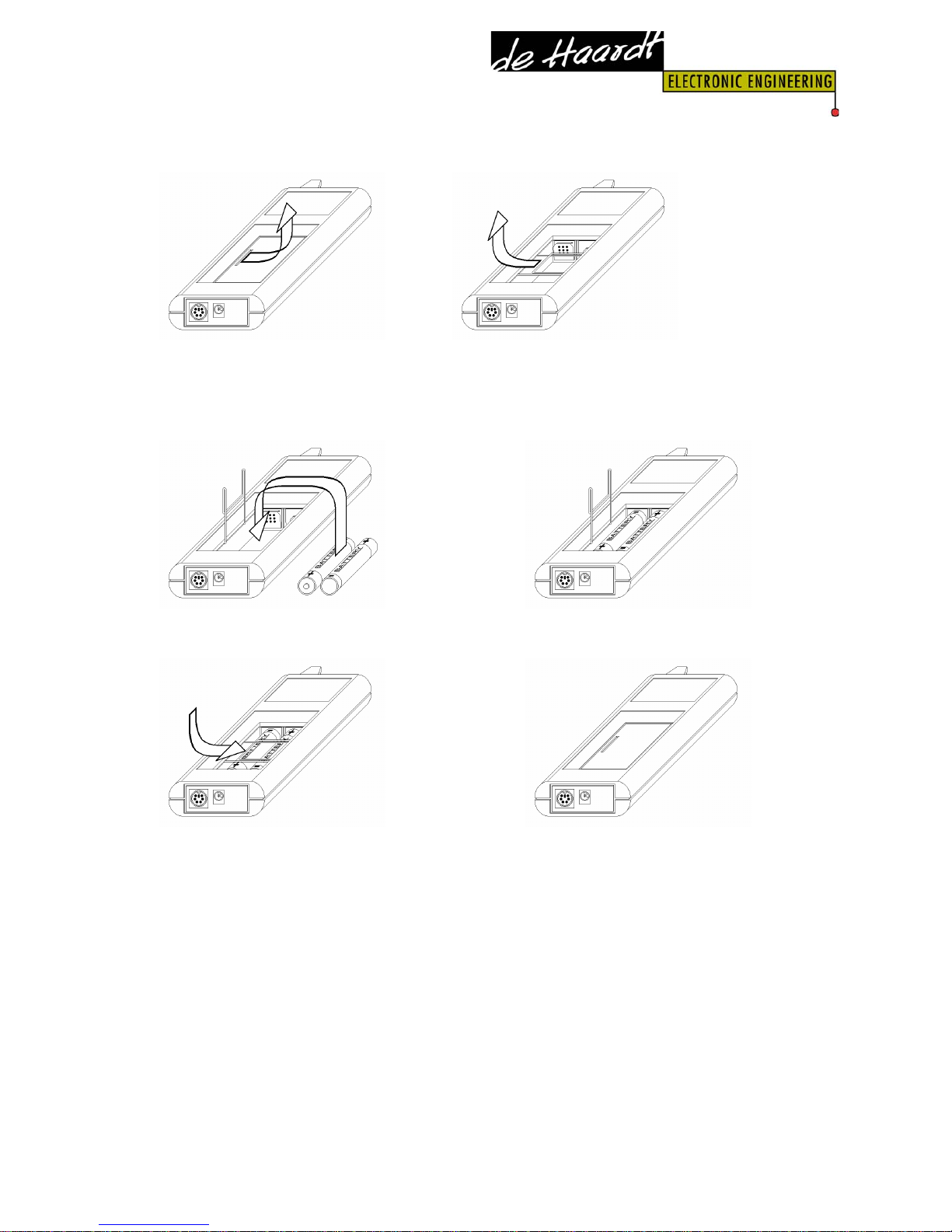
4.1.1 Placing the batteries
The Xtra.Remote Control Unit can be equipped with 2
rechargeable NiMH batteries type AA. To place these
batteries the battery cover must be opened. Pull the 'lock'
spring towards the inside. Place the batteries according to
the symbols + and – labeled in the battery compartment.
Close the battery compartment by sliding the spring to the
right and close the cover.
Important:
• Only use rechargeable batteries of the type NiMh,
and no conventional batteries.
• Do not use old and new batteries together, or from
different manufacturers.
• Batteries contain chemical substances. Treat old
batteries as chemical waste and don’t leave them in
the vicinity of children.
Manual Xtra.Remote Kart &
Track Control System
7
1. Open battery cover 2. ‘Unlock’ the spring
3. Place the batteries in the battery compartment
4. close the spring 5. Close the cover
The provided rechargeable batteries must be charged before
use.
Manual Xtra.Remote Kart &
Track Control System
8
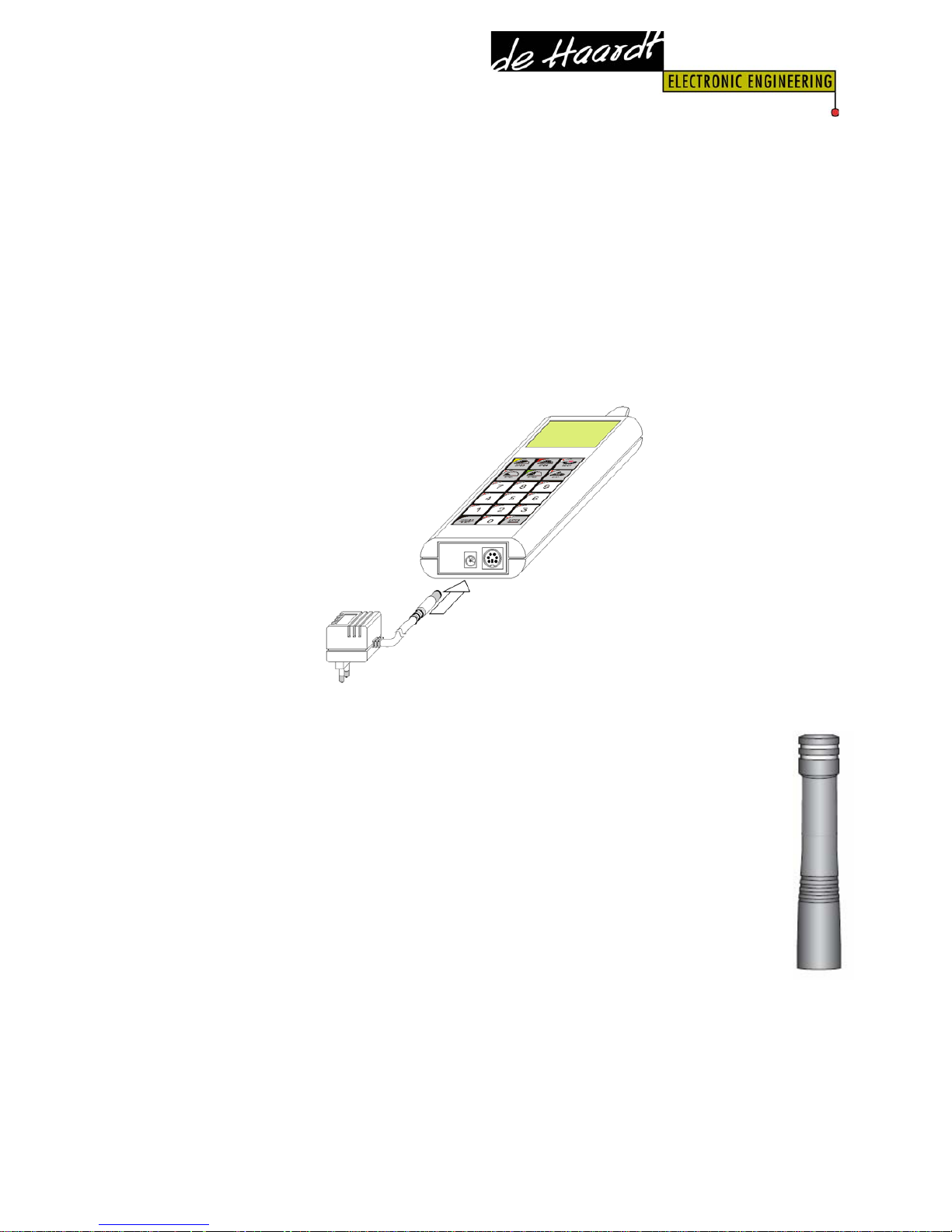
4.1.2 Connecting the adapter
Connect the provided adapter to the DC power connector of
the Xtra.Remote Control unit and plug the adapter into the
mains power supply socket.
By connecting the adapter to the Remote Control it can be
used without batteries and/or charge the NiMH batteries in
the Xtra.Remote Control.
4.1.3 Connecting the antenna
The antenna of the Xtra.Remote Control can be fastened
on the top side connector by turning clockwise. Do not
apply excessive force as this could cause damage!
Caution : Do never use the antenna as a handle. Do
not lift the Xtra.remote control out of the carriage
bag by its antenna.
Manual Xtra.Remote Kart &
Track Control System
9
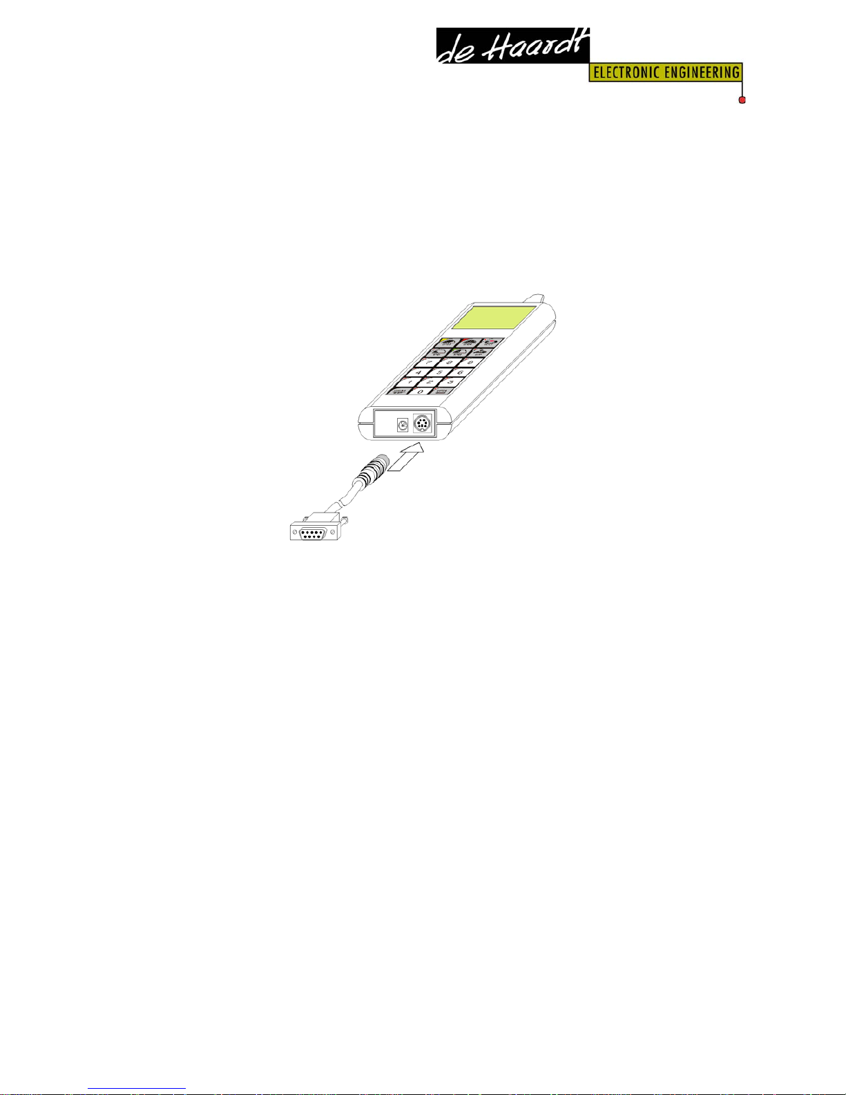
4.1.4 Connecting to a Personal Computer
The Xtra.Remote Control can be connected to a PC by
means of a serial cable.
This serial link gives third parties the ability to control and
monitor the karts and track by means of a PC.
4.2 Xtra.Shutdown transponder
To be able to limit the speed of the karts from a distance,
the Xtra.shutdown transponders have to be assembled on
every kart (Xtra.TwinShutdown transponder for karts
powered by 2 engines). Every Xtra.Shutdown transponder
has a unique serial number, and by using the Xtra.Remote
Control it is possible for the user to give every
Xtra.shutdown transponder a Kart, group(s) and/or track
number.
Assigning a track number to the Xtra.Shutdown transponder
gives the possibility, when other go-kart circuits are close
by, to control the karts independently of each other. A
maximum of 4 tracks can be assigned.
This gives for example the possibility to assign a kart
number 1 on every circuit, and only a Remote Control which
Manual Xtra.Remote Kart &
Track Control System
10
is also assigned to the same track will have control over this
kart number.
The Xtra.Shutdown transponder is standard provided with a
connection for a brake switch. If a brake switch is connected
and activated by pressing the brake pedal of the go-kart,
the RPM of the kart is reduced.
On the Xtra.Shutdown transponder there is also a plug for a
network connection. By means of this network connection
(future) applications or devices can be linked, and
communicate with the Xtra.Shutdown transponder.
Warning:
Continuous use of the Xtra.Shutdown
transponder as a speed-limiting device may degrade the
lifespan of the engine.
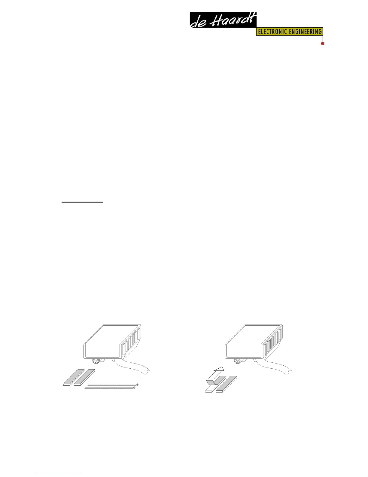
4.2.1 Assembly of the Xtra.Shutdown transponder
The Xtra.Shutdown transponder is easy to install on the
kart, by means of it’s V-shape based housing. It is possible
to mount the housing both on round and / or square tubes.
By means of 2 tiewraps and 2 double sided adhesive strips
it is possible to mount the Xtra.Shutdown transponder in
most cases.
Manual Xtra.Remote Kart &
Track Control System
11
Place each of the double sided adhesive strips on one of the
slanting V sides on the bottom part of the Xtra.shutdown
transponder.
Next, place the Xtra.Shutdown transponder on for example
a frame tube of the kart, so that the adhesive strips keep
the Xtra.Shutdown transponder in place.
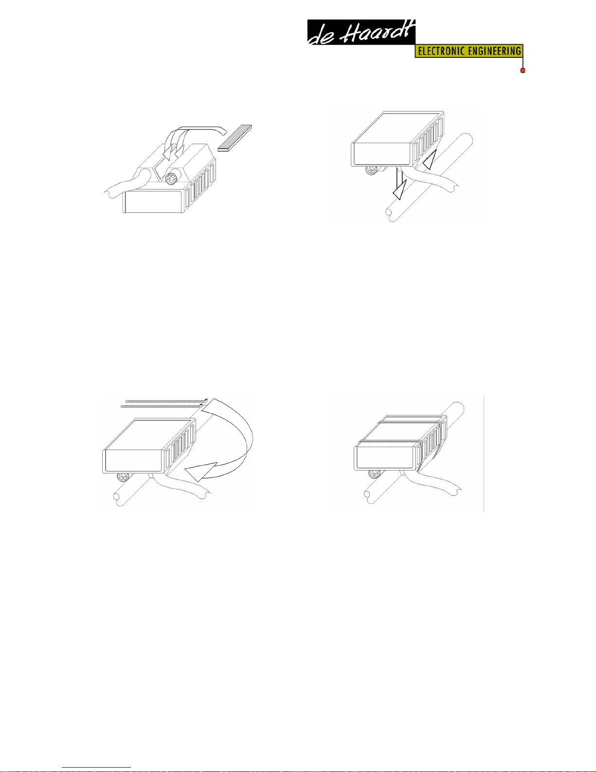
Fasten the Xtra.Shutdown transponder with 2 tiewraps, and
ensure that these can not tremble off during the use of the
kart or by other causes.
Warning: The best way of mounting the transponder to
yourgo- kart depends heavily on your karts framework.
Therefore the mounting instructions mentioned above
should be considered as guidelines only. Because the
transponder operates in a rough environment, every now
and then a routine check-up must be made to ensure that

Manual Xtra.Remote Kart &
Track Control System
12
the transponder is still properly fastened and shows no
visual damage.
Keep the upper part (Flat part) of the Xtra.Shutdown
transponder away from any metal parts or wires and never
place it facedown towards the track concrete.
There is no kart number printed on the Xtra.Shutdown
transponder, only a serial number. Assigning a kart number,
group number and / or track to the Xtra.Shutdown
transponder is explained in chapter 'Menu-> Shutdown tp->
Assign'.
Assigning the numbers is only possible when the
Xtra.Shutdown transponder has been connected to the
engine, which is running.
When a new Xtra.Shutdown transponder is bought, the
default kartnumber is factory set to the last 2 digits of the
serial number.
Warning: To prevent personal injury during installation of
the Xtra.Shutdown transponder(s), the kart engine must be
turned off.
Warning:
Make sure that the Xtra.Shutdown transponder is
not damaged in case of an accident or when the driver steps
out of the kart. Do not mount the shutdown transponder
next to the ignition.
Manual Xtra.Remote Kart &
Track Control System
13
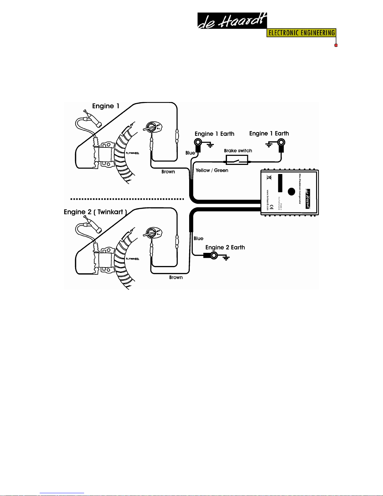
4.2.2 Electrical connection of the Xtra.Shutdown
transponder
Depending on the type of Xtra.Shutdown transponder you
use, one or 2 cables are coming out of the Shutdown
transponder. The second cable on an Xtra.Twin Shutdown
transponder is connected in a simular fashion as the cable
for the first engine, and therefore not specifically described
in the text below.
The cable eye at the end of the blue wire of the
Xtra.Shutdown transponder has to be fixed on the blank
metal (mass) of the Honda GX… engine with a screw.
Pull apart the 2 connectors coming from the engine’s On/Off
switch and connect these to the connectors of the
Xtra.Shutdown transponder which are attached to the
brown wire.

Manual Xtra.Remote Kart &
Track Control System
14
If the brake switch is used, the connector has to be
connected to the yellow-green wire (possibly this wire has
to be extended). The maximum length of the original wire
together with the extension cable is 2 meters. The other
contact of the brake switch must be fixed on the blank
metal (mass) of the Honda GX… engine.
Important: Fix the mass wire of the brake switch and / or
Xtra.Shutdown transponder always on a mass point of the
engine block itself. Under no circumstances fix them on
another mass point that is on the kart. (like for example a
frame tube)
The Xtra.Shutdown transponder is fitted with a network
port. By way of this network port the Xtra.Shutdown
transponder can be connected to other on-kart electronics.
Warning: Always put the protection cap on the
Xtra.Shutdown transponder’s
network port when this port is
not used ! Be sure that the
protection cap is fully covering
all outside metal parts of the
network port connector.
It’s not allowed to connect any
device which is not approved by
De Haardt to this network port.
Manual Xtra.Remote Kart &
Track Control System
15
4.3 Xtra.Range Extender / Accesspoint
The Xtra.Range Extender / Accesspoint has a “relay”or
“repeater” approach which helps to cover large areas,
reflective corners and hard-to-reach areas on the race
circuit.
The unit can also be used as an access point in case it is
connected to the serial port of an external device. This gives
for example third parties the ability to control and monitor
the Track and Karts by means of a PC.
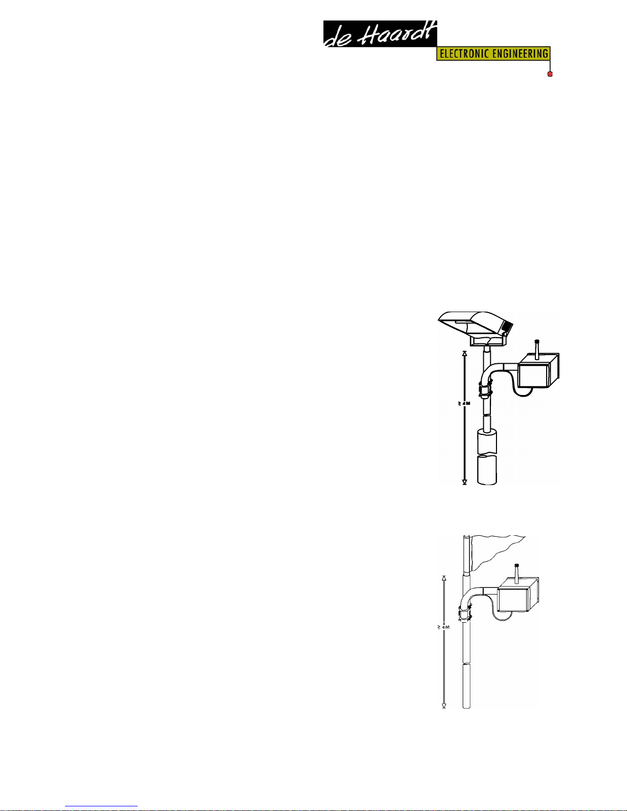
4.3.1 Mounting of the Xtra.Range
Extender / Accesspoint
The operating range of the Xtra.Range
extender / Accesspoint depends on the height
of the antenna above the ground, line of
sight, and obstructions in the line of sight.
Therefore we suggest for range extension on
outdoor circuits to mount the Xtra.Range extender / Access
point on a mast of at least 4 meters high or on one of the
track light poles.
Locate the mast(s) on (a) strategic
position(s), in the centre of the operating
areas where obstacles (like trees and
buildings) in the line of sight are at a
minimum.
If you are mounting the antenna on a roof, it
must be at least 1m above the roof line.
Manual Xtra.Remote Kart &
Track Control System
16
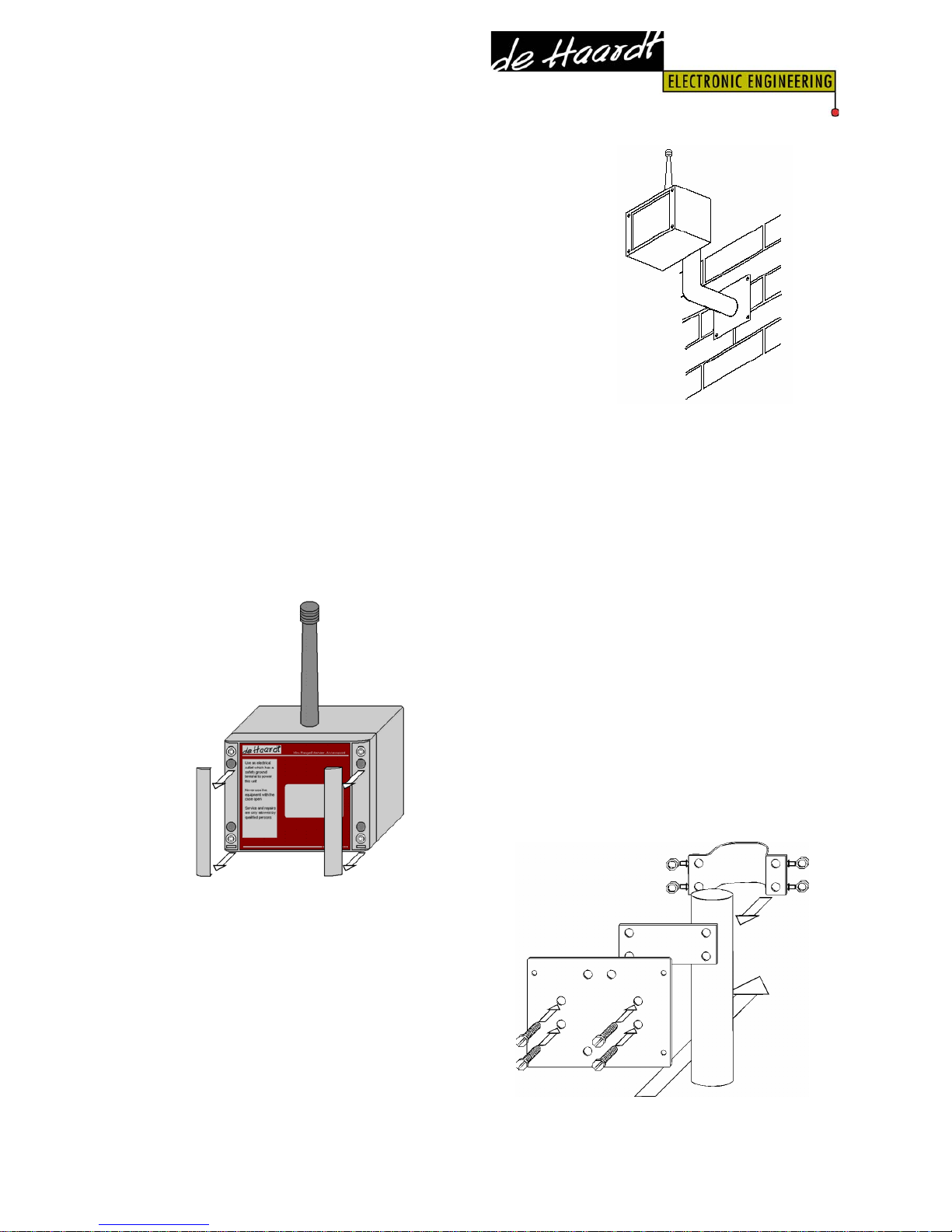
For indoor use the Xtra.Range extender /
Accesspoint can be mounted for example
on a fixure which is located on a building
wall or on a pole. The fixture must
provide a distance of at least 35cm
between the Xtra.RangeExtenderAccesspoint and the wall.
Always position the Xtra.Range Extender such way that the
antenna is in vertically position and pointing to the sky.
Guideline for mounting the Xtra.Range extender / Access
point on a pole. (For illustration only):
Lift the plastic design covers
of the Xtra.RangeExtenderAccesspoint from the
aluminium housing.
The 4 fastening holes are now
visible. (It is not necessary to
open the housing for
mounting the unit!)
Mount a baseplate to the
support tube. This can be done
by a bridge support. Use self
locking nuts to prevent from
loosening by vibration.
 Loading...