

Defy 900 Owner's Manual

Owner’s
Manual
CONICAL CHIMNEY HOOD
STAINLESS
CONTENTS
2 Installation
3 Electrical Installation
3 The Controls
4 Operation
4 Maintenance
4 The controls
5 Cleaning and maintaining
stainless steel
6 Problem check
6 Service
www.defy.co.za
CONICAL CHIMNEY
STAINLESS
HOOD
The manufacturer strives for
continuous improvements. For
this reason, the text and
illustrations in this book are
subject to change without notice.
Part Number 064 782
Installation
CAUTION
The exhaust air from the chimney hood must not be discharged into a flue or chimney
which is used for exhausting the fumes from other appliances burning gas or fuels.
Please ensure that the regulations concerning the discharge of exhaust air have been
fulfilled. ( SABS IE C60335-2-31)
S L I M L I N E
113
MIN 650
FOR ELECTRIC HOB
MIN 750
FOR GAS HOB
TOP CHIMNEY
FIXING BRACKET
KEYHOLE
SLOTS
RETAINER
HOLES
OUTLET VENT SLOTS IN
LOWER CHIMNEY
Y-PIECE FOR
RECIRCULATED AIR
SPIGOT FOR
OUTSIDE VENTING
FLANGE
Installation
Please read these instructions carefully before installing and attempting to operate the appliance.
CAUTION
The exhaust air from the chimney hood must not be discharged into a flue or chimney which is
used for exhausting the fumes from other appliances burning gas or fuels.
Please ensure that the regulations concerning the discharge of exhaust air have been fulfilled.
( SABS IE C60335-2-31)
S L I M L I N E
113
MIN 650
FOR ELECTRIC HOB
MIN 750
FOR GAS HOB
TOP CHIMNEY
FIXING BRACKET
KEYHOLE
SLOTS
RETAINER
HOLES
OUTLET VENT SLOTS IN
LOWER CHIMNEY
Y-PIECE FOR
RECIRCULATED AIR
SPIGOT FOR
OUTSIDE VENTING
FLANGE
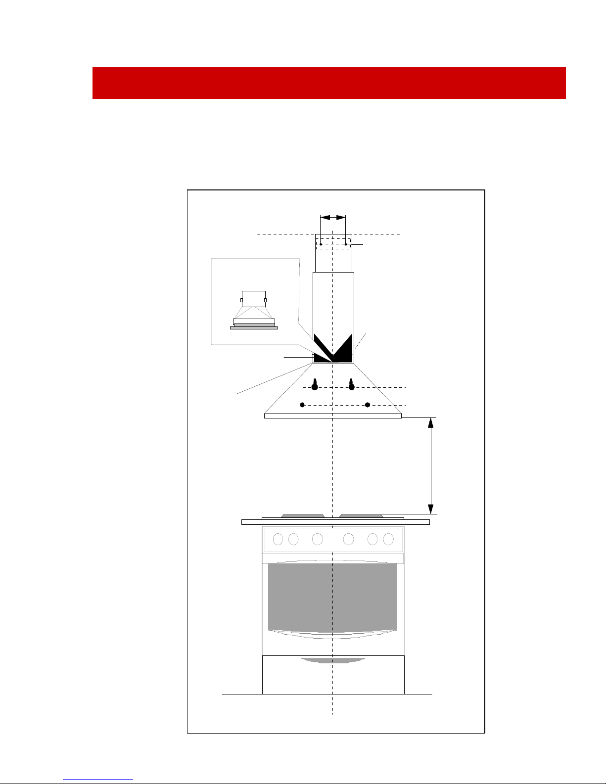
Wall mounting.
Remove the aluminium grease filters (perforated plates) by gently pulling down on the
handles so that the interior of the cooker hood and the keyhole slots are exposed.
The hood must be mounted directly over the cooking area. The minimum distance
between the cooking surface and the underside of the hood must be 650 mm. for
electric cookers and 750 mm. for gas burners.
Get two people to help you hold the body of the hood in position against the wall and
using a pencil, mark the two keyhole slots and the two retaining hole positions, on the
wall.
Using a masonry bit, drill a hole at the top of each marked slot and at the centre of the
retaining hole marks. Insert a rawl plug into each hole.
Using pan-head screws with a head diameter slightly smaller than the bottom opening
of the keyhole slot, insert the screws part way into the marked keyhole positions.
Leave about 5 mm of the screws proud of the wall.
Installation continued
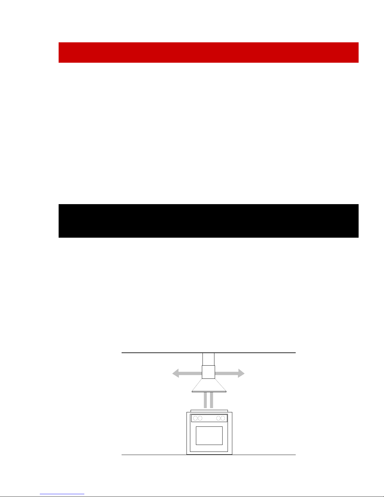
The Hood has the ability to either circulate the filtered air back into the kitchen o
r
to exhaust the filtered air through an outside wall or chimney pipe. Decide on which
option best suits your needs and proceed with the installation accordingly
Option 1—Re- circulated air
Fit the metal Y-piece on to the main body using the self tapping screws supplied
Fit the larger of the two chimney pieces to the main body using the two self tapping
screws supplied.
Lift and hang the hood and chimney assembly onto the two keyhole mounting screws.
Fit and tighten two suitable retainer screws ensuring all the while that the hood is
level.
Using the top chimney fixing bracket as a template, mark the hole positions. Drill and
attach the fixing bracket to the wall at the marked positions. Reposition the top
chimney piece so that the side holes correspond with the holes in the fixing bracket
and secure with two self tapping screws.
 Loading...