

Defy 621 Kitchenmaster Owner's Manual

PAGE 1 OF12
Part Number 068 121
You can rely on Defy. To simplify
Please register your
product at
www.defy.co.za
The Manufacturer
strives for continuous
improvements.
For this reason, the text
and illustrations in this
book are subject to
change without notice.
Kitchenmaster
Stove
OWNER’S MANUAL
FOR MODEL:
621 Kitchenmaster
Solid plates
CONTENTS
Introduction
Unpacking
Installation
Electrical installation
Owners responsibility
Anti-tilt mechanism
Fitting the removable
splashback
Safety advice
The control panel
6 Position selector knob
Using the oven
Caring for solid plates
Utility drawer
Problem check
Cleaning the oven
Oven light
Removable oven door
Do and Don’t guide
Purchase details
Service centres
Warranty
2
2
2
2
2
3
4
5
6
6
7
8
8
8
9
9
9
10
10
11
12

PAGE 2 OF12
Introduction
Congratulations on the purchase of this quality appliance. We trust that you will enjoy
many years of trouble free use. Please read these instructions carefully before using the
appliance. This manual will provide you with information on how to operate and care for
your appliance in order that you gain the maximum benefit from it.
Unpacking
• Please ensure that packaging material is disposed of in a responsible manner.
• Remove all packing from the oven cavity and position the accessories.
• If the appliance is damaged in any way, do not use it. Report the damage to your dealer,
who will take the necessary corrective action.
Installation
• Surfaces immediately adjacent to the oven should be able to withstand temperatures of
up to 100°C without delaminating or discolouring.
Electrical installation
This appliance must be earthed and the manufacturer and the seller do not accept
responsibility for any damage due to incorrect installation or electrical connection.
This appliance should not be connected through an earth leakage system.
Refer to S.A.N.S. 10142
Connection to the power supply
This appliance has a ‘Y’ type supply cord connection and must be installed by a licensed
electrician, who will ensure that the stove is correctly connected and safely earthed. The
rated current is printed on the serial number label attached to the stove upper back panel.
The appliance must be connected to the mains through an All pole isolating switch which
has a minimum clearance between the contacts of 3 mm. in All poles.
A means for disconnection must be provided in the fixed wiring.
Owner’s responsibility
Since the following are not factory faults, they are the owner’s responsibility:
Damage to exterior finish.
Breakage of glass and other components.
Replacement of the light bulb.
Damage through improper installation or use of the appliance.
Damage caused by moving the appliance.
PAGE 3 OF12
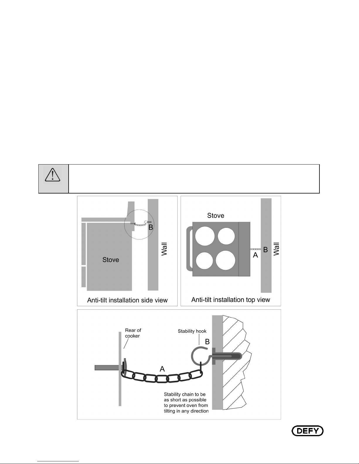
Anti-Tilt mechanism
• “A” 1 x Stability chain
• “B” 1 x Stability hook with anchor sleeve
• “A” is factory fitted at the rear of the stove in the centre. (See overleaf for instructions
if the removable splashback is to be fitted)
• Position the stove and move “A” to touch the wall behind the stove.
• Mark the hole where “A” touches the wall behind the stove.
• Move the stove away from the wall to allow for an area to work in.
• Using a 8.0 mm concrete bit, drill a hole at the marked position.
• Using the Stability hook and anchor sleeve “B”, firmly secure “B” to the wall.
• Slide the stove back in position and engage the stability chain “A” onto the Stability
hook “B”.
• The stove is then secured and will not accidentally tilt if downward pressure is applied
to the open oven door.
WARNING: All stoves can tilt if you or a child sit or lean on an open oven
door. Safety regulations stipulate that the ANTI-TILT mechanism supplied with the stove,
must be fitted as shown.

PAGE 4 OF12
Fitting the removable splashback
Remove the splashback (B)
(recessed in the polystyrene) from the
polystyrene packaging.
Align the 4 splashback holes with the
4 holes on the top back of the stove.
Insert screws numbered 1, 2, 3 & 4
through the splashback into the stove.
Fasten the screws 1, 2, 3 & 4 to
secure the splashback in place as
indicated in the diagrams.
Please see instructions on the previous page regarding correct fitment and
securing of the anti tilt mechanism (A) to the wall.
 Loading...