

Page 1
SoloCinema Studio
Owner’s Manual
Page 2

Thank you for choosing Denitive Technology
Please take a few moments to fully read this owner’s
manual and familiarize yourself with the proper installation
and setup procedures.
Unpack and Inspect your
SoloCinema Studio
Please unpack the components carefully, removing the subwoofer rst
as indicated on the carton and then the sound bar. Inspect for shipping
damage. Any visible damage most likely occurred in handling after it left
our plant and should be reported at once to your retailer, distributor, or
shipping company. Please save all cartons and packing materials in case
you move, or need to ship your SoloCinema Studio.
Contents
Safety Precautions 2
What’s in the Carton 3
Specications 3
Placement Options 4
Tabletop Mounting 4
Mounting the Sound Bar on the Wall 5
Tips for Mounting the Sound Bar 5
Connecting Your System 6
Connection Method #1 6
Connection Method #2 6
Connection Method #3 7
Connection Method #4 7
Subwoofer 8
Audio Optimizer Remote Control 8
Sound Bar Controls and LED Display 9
On-Screen Display (OSD) Set-up Menu Functions 10
1. BLUETOOTH 10
2. NIGHT MODE 10
3. IR LEARN 11
4. SUB CONNECTION 11
5. SOLO SURROUND ARRAY (SSA) IMMERSION 11
6. HDMI AUDIO 12
7. SYSTEM 12
Using High Speed HDMI Cables 12
Tips and Troubleshooting: FAQ’s 13
IR Remote Control Function and Data List 14
Service 15
Warranty 15
Page 3

Safety Precautions
1. Read these instructions.
2. Keep these instructions.
3. Heed all warnings.
4. Follow all instructions.
5. Do not use this apparatus near water.
6. Clean only with dry cloth.
7. Do not block any ventilation openings. Install in accordance with
the manufacturer’s instructions.
8. Do not install near any heat sources such as radiators, heat
registers, stoves, or other apparatus (including amplifiers) that
produce heat.
9. Do not defeat the safety purpose of the polarized or grounding
plug. A polarized plug has two blades with one wider than the
other. A grounding plug has two blades and a third grounding
prong. The wide blade or the third prong is provided for your
safety. If the provided plug does not fit into your outlet, consult an
electrician for replacement of the obsolete outlet.
10. Protect the power cord from being walked on or pinched
particularly at the plugs, convenience receptacles, and at the point
where they exit from the apparatus.
11. Only use attachments/accessories specified by the manufacturer.
12. Use only with the cart, stand, tripod, bracket, or table specified by
the manufacturer, or sold with the apparatus.When a cart or rack is
used, use caution when moving the cart/apparatus combination to
avoid injury from tip-over.
13. Unplug the apparatus during lightning storms or when unused for
long periods of time.
14. Refer all servicing to qualified personnel. Servicing is required
when the apparatus has been damaged in any way, such as when
power supply cord or plug is damaged, liquid has been spilled
or objects have fallen into the apparatus, or apparatus has been
exposed to rain or moisture, does not operate normally, or has
been dropped.
15. To reduce the risk of fire or electric shock, do not expose this
apparatus to rain or moisture. The apparatus shall not be exposed
to dripping or splashing, and objects filled with liquids,such as
vases, shall not be placed on apparatus.
16. The mains plug/appliance coupler is used as disconnect device;
the disconnect device shall remain readily operable.
CAUTION
RISK OF ELECTRIC SHOCK
DO NOT OPEN
ATTENTION: RISQUE DE CHOC ELECTRIQUE - NE PAS OUVRIR
17. This lightning flash with arrowhead symbol within an equilateral
triangle is intended to alert the user to the presence of non-insulated
“dangerous voltage” within the product’s enclosure thatmay be of
sufficient magnitude to constitute a risk of electric shock.
WARNING: To reduce the risk of electric shock, do not remove
cover (or back) as there are no user-serviceable parts inside. Refer
servicing to qualified personnel.
The exclamation point within an equilateral triangle is intended
to alert the user to the presence of important operating and
maintenance instructions in the literature accompanying the
appliance.
18. Protective grounding terminal. The apparatus should be connected
to a main socket outlet with a protective grounding connection.
19. No naked flame sources, such as lighted candles, should be
placed on the apparatus.
CAUTION! To reduce the risk of electric shock and re, do not remove the cover or
back plate of this device. There are no user serviceable parts inside. Please refer all
servicing to licensed service technicians.
CAUTION! The international symbol of a lightning bolt inside a triangle is intended to
alert the user to un-insulated “dangerous voltage” within the device’s enclosure. The
international symbol of an exclamation point inside a triangle is intended to alert the
user to the presence of important operating, maintenance and servicing information
in the manual accompanying the device.
CAUTION! To prevent electrical shock, match wide blade of plug to wide
slot, fully insert.
CAUTION! To reduce the risk of electrical shock, do not expose this equipment
of rain or moisture.
2 Definitive Technology ° Owings Mills, MD
Page 4
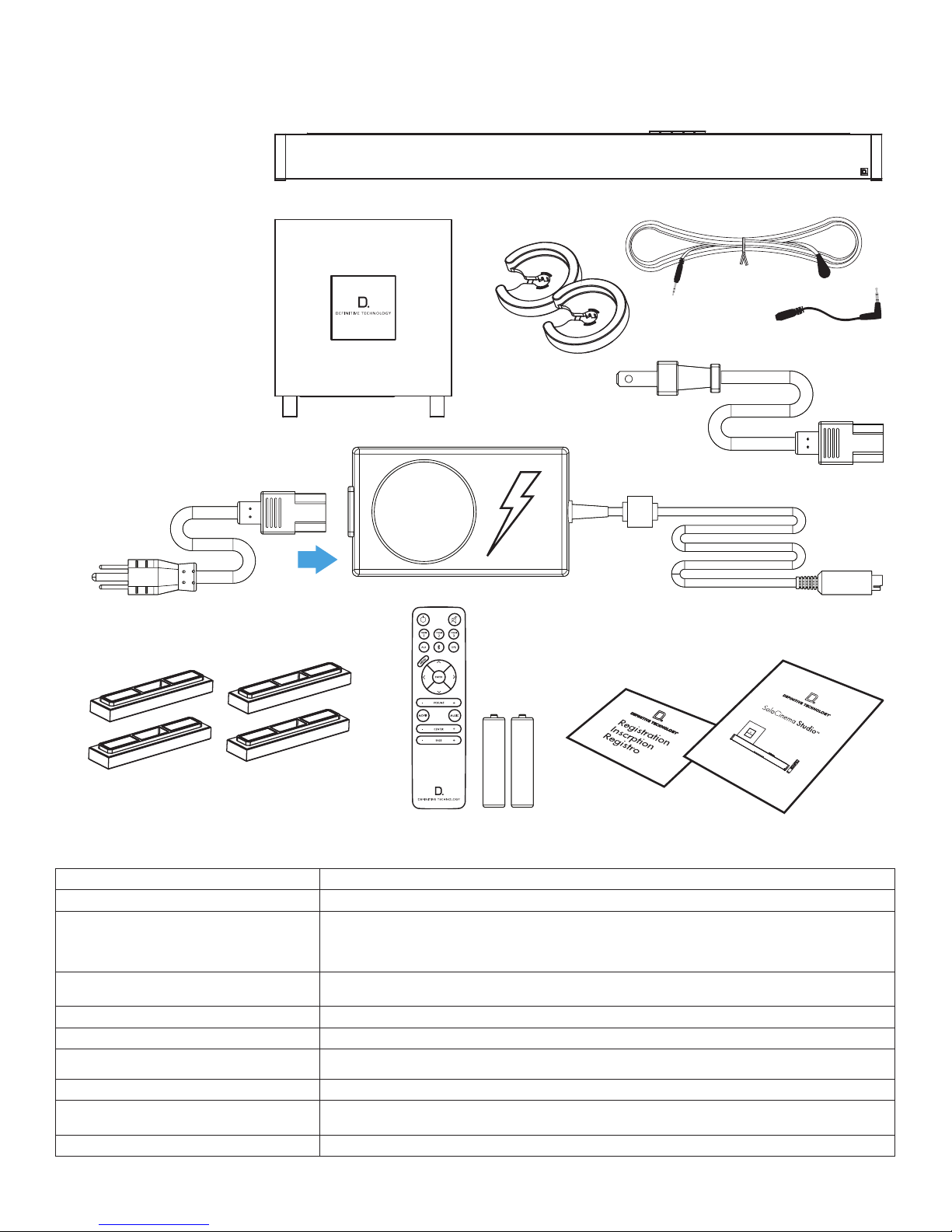
What’s in the Carton
Included in your SoloCinema Studio carton:
1. sound bar
2. subwoofer
3. power cord
4. power supply
5. subwoofer power cord
6. two spacers for wall mounting
7. four magnetic feet
8. user guide
9. online registration card
10. remote control
11. batteries
12. IR adapters
(input and output)
1
2
12
6
5
4
3
10
7
8
11
AAA
AAA
Specications
Driver Complement - Bar 6 x 3.0" mid woofer drivers, 3 x 1" aluminum dome tweeters
Number of channels 5.1
Dimensions: Bar 43" W x 3.5" H x 3.15" D
Inputs/Outputs HDMI 1.4a in (3), HDMI 1.4a out (1), Toslink Optical input (1), Analog 3.5 mm mini-jack AUX (1), factory update (1)
Wireless Input Bluetooth® wireless technology with aptX
Power Output: Bar 120 Watts
Supported Surround Formats Dolby Digital®, DTS
109 W x 8.9 H x 8 D (cm)
Depth including wall mount spacers 3.8" (9.5 cm)
Wall keyhole slots 32" apart ( 81.28 cm)
(rmware updates ONLY; not a source input)
®
®
9
Driver Complement: Subwoofer (1) 8" long throw woofer in sealed enclosure
Dimensions: Subwoofer 12.5" W x 12.5" H x 12.5" D;
Power Output: Subwoofer 200 Watts
32cm W x 32cm H x 32cm D
more information visit our website at www.definitivetech.com 3
Page 5
Placement Options
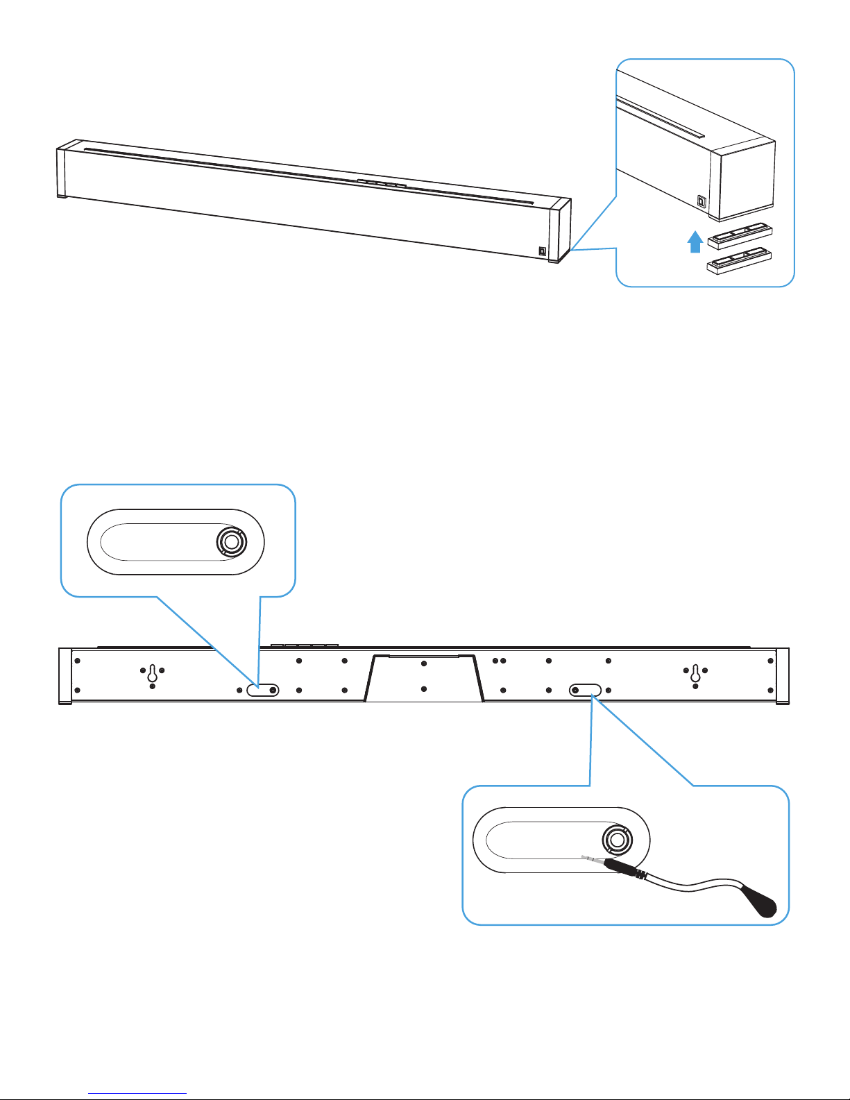
Tabletop Mounting
SoloCinema Studio comes with extra riser feet (two per side) that
magnetically attach to the bar to raise it as much as 15.2 mm (5/8")
off the tabletop so the bar will clear the TV’s protruding table stand.
Attach magnetic feet: Peel off the protective cover and expose the
magnets. Attach the feet to the bottom edge of the sound bar.
What if the bar blocks your TV’s remote IR receiver?
Note: The SoloCinema Studio could block your TV’s remote “eye,”
making it impossible to control the TV via remote control, so we
supply an IR asher. Plug the asher into the bar’s IR output and
position it in front of the TV’s eye.
IR INPUT
For custom installations: the IR input is more likely to be used with a
home automation system, like Crestron or Control 4. This is often just an
electrical connection to a piece of equipment.
IR OUTPUT
Caption: The LED side has an adhesive backing and can be mounted to the TV’s IR
4 Definitive Technology ° Owings Mills, MD
Page 6
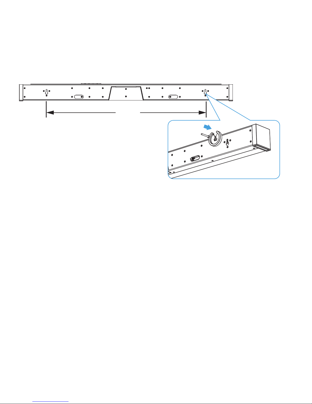
Mounting the Sound Bar on the Wall
The SoloCinema Studio sound bar has built-in keyhole slots so you can
wall-mount it beneath your wall-mounted television. Spacers are included
to help secure and install your sound bar on the wall.
Note: DO NOT mount the sound bar directly to the wall. You must use the
supplied wall-mount spacers to ensure proper operation and reliability.
Note: DO MAKE SURE you are using a wall anchors capable of
supporting the sound bar.
812.8 mm
[32"]
Tips For Wall Mounting the Sound Bar
Leveling the sound bar: Use a bubble level to make sure the bar is level.
Mark holes with pencil, taking the keyhole slot measurement from the bar.
Drill Screw Holes in Wall: Pre-drill the pilot-hole locations for mounting
screws (not included). Use screws rated to hold securely in the wall
material and have screw heads at least 0.33" (8.5 mm) in diameter.
NOTE: Measure Twice Make sure the sound bar clears the ceiling,
adjacent walls, corners, beams, lighting xtures and door/window
frames. Leave at least 1-2" (25-50 mm) above the sound bar location to
allow the sound bar to slide onto the screws. Make sure the center of the
bar is centered with the TV screen’s center point.
Hang Sound bar on Posts: Line up the bar so that the screw heads
slide into the keyhole slots. Slide the bar down so the screw heads
hold the bar rmly in place.
Caption: The sound bar can be mounted on a wall with built-in keyhole slots for a
total installed on-wall depth of only 3.8" (9.5 cm). Use the supplied rubber cups
that hold the bar off the wall.
more information visit our website at www.definitivetech.com 5
Page 7

Connecting Your System
Connection Method #1:
All sources into your SoloCinema Studio
via HDMI (recommended)
HDMI
IN
BD
Cable
The HDMI cable runs from the HDMI output of the SoloCinema Studio
to an HDMI input on the TV set.
You will use the SoloCinema Studio remote for switching between the
sources you have connected to the system (Blu-Ray player, cable box etc.).
We recommend this method; it ensures the highest resolution audio and
video signals for the best possible audio performance.
Note: For greater convenience, you can program the SoloCinema Studio
to respond to the power, volume, mute, and source select commands of
your TV or cable box remote. See the “IR Learn” section of the
OSD Set-up Menu Functions for instructions.
Connection Method #2:
All sources into your TV, with TOSLINK optical audio output
from the TV set to the sound bar.
TV
Opt OUT
BD
Cable
The TV does all the switching between sources, and the sound bar is
always set to INPUT #5.
Note: Most TV’s cannot pass a Dolby Digital or DTS 5.1 channel audio
signal through an optical audio output connection. They can only pass
2 channel stereo through Toslink. The SoloCinema Studio will simulate a
surround experience, but it will not be as effective as when processing a
true 5.1 digital surround signal. This hookup method offers convenience:
most functions (including source switching) can be done through one
remote control, such as your cable box or TV remote. But you won’t get
the best system sound quality, or be able to use all of the features of the
SoloCinema Studio, including your OSD (on-screen displays).
6 Definitive Technology ° Owings Mills, MD
Page 8

Connection Method #3:
All sources into your TV with 3.5mm analog
mini-jack to the sound bar.
TV
BD
Cable
Note: Some older TV’s have only an analog output connection. In
this scenario, the TV does all the switching between sources and the
SoloCinema Studio is always set to INPUT #4. A Dolby Digital or DTS
digital audio signal cannot be passed through a TV’s analog output
connection. The best audio signal quality that can be reproduced using
this method is two-channel stereo audio. This method is the least-preferred
connection method of the three described here.
Note: You can also connect a smartphone, tablet or other mp3 player
using the 3.5mm mini jack to the sound bar.
Connection Method #4:
Bluetooth Streaming
The SoloCinema Studio is an excellent system for playing all kinds of
music from smart phones, tablets and laptop PCs, thanks to the bar’s
built-in Bluetooth streaming capability.
Bluetooth Source/Pairing: Press and hold the Bluetooth button on the
sound bar to pair the sound bar with a Bluetooth device, or you can also
press and hold the BT button on the remote to pair.
Note: Devices equipped with Near Field Communication (NFC) can pair
with the SoloCinema Studio. Simply touch the device to the sound bar and
they’re paired. Touch the device again, and it disconnects.
more information visit our website at www.definitivetech.com 7
Page 9

Subwoofer
FCC ID:IPUSOLOCINSTUDIO / IC:10392A-SOLOSTUDIO
CAN ICES-3 (B)/NMB-3(B). MODEL: SOLOCINEMA STUDIO
Note: The sound bar and the subwoofer come paired from the factory.
All you do is plug in the subwoofer’s power cord and turn on the ON/
OFF POWER switch. When you turn on the sound bar, both the bar and
subwoofer will establish a communication link.
Audio Optimizer Remote Control
1. Power: Press Power to toggle the unit on/off. A front panel
light recognizes the command. The subwoofer also turns
on when it sees a signal from the sound bar. Please allow
approximately 10 seconds for the system to turn on.
2. Mute: Turns sound off while the system remains on.
Press MUTE again to return the sound to the previous
volume level. The On-Screen Display (OSD) pop-up
menu confirms your selection
3. Sources: HDMI 1, HDMI 2, HDMI 3, AUX, Bluetooth®,
Optical. These enable you to select sources, such as a Blu-ray
player or tuner that you’ve connected to the rear panel source
inputs. The OSD pop-up confirms your selection.
4. Menu: Press MENU to call up the On-Screen Display
(OSD). This shows a series functions that can be accessed
to make system changes. Press MENU again to exit from
the OSD once you’ve completed making your selections.
See the section titled “On-Screen Display set-up menu
functions” for more detail.
5. Cursor control/Enter button: Press the four arrow keys, with
the ENTER button in the middle, to select and adjust menu
items such as surround immersion level. The OSD pop-up
menu confirms your selection.
6. Master Volume up/down (+ –): Press (+) to increase
the system volume. Press (–) to decrease the volume.
Volume is displayed on the front panel LEDs and on
the OSD pop-up menu.
7. Movie: Press MOVIE to
optimize the bass output,
surround processing and
other sound parameters, so
movies sound their best. The
OSD pop-up menu confirms
your selection.
8. Music: Press MUSIC
to optimize the sound
characteristics for
maximum music
enjoyment. The OSD
pop-up menu confirms
your selection.
9. Center + or – : Use to
increase or decrease the
center channel volume,
independently of changing
the overall volume level. For
example, if family members
are sleeping, you may
want to improve the movie
dialog audibility without
significantly increasing the
overall volume level.
10. Bass output up/down (+
–): Press (+) to increase the
bass output of the subwoofer
relative to the system volume.
Press (–) to decrease the bass
output. The OSD pop-up
menu confirms your selection.
6
9
3
7
1
4
2
5
8
10
8 Definitive Technology ° Owings Mills, MD
Page 10

Sound Bar Controls and LED Display
1. POWER: Press to turn on the system (sound bar and wire-
less subwoofer).
2. SOURCE (Symbol ): Six LED lights correspond to each of the six
source inputs. Example: You want to play a Blu-ray disc and are
currently playing another source on input #1. Your Blu-ray player
is connected to source input #2. Simply touch this switch once to
select the input.
Please note: When advancing more than one source, please allow
for a few seconds of delay.
3. Volume DOWN: Press – to decrease the system volume. A
row of LED’s displays the volume level. It takes 4-5 presses to
change the LED, but you will hear, and see on the OSD pop-up
screen, that the volume is decreasing.
4. Volume UP: Pressing + to increase the system volume, with
a corresponding change in the LED display/OSD.
5. Bluetooth Source/Pairing: Press once to select Bluetooth
Input. Press and hold to pair the sound bar with a
Bluetooth device.
Note: you can also press and hold the BT button on the remote
to pair.
®
more information visit our website at www.definitivetech.com 9
Page 11

On-Screen Display (OSD) Set-Up
Menu Functions
(only available when using HDMI hook-up method)
With your TV ON, press the MENU button on the remote. The OSD screen
appears on your TV. To exit the menu at any time, just press the MENU
button. The functions:
SOLOCINEMA STUDIO MENU
BLUETOOTH
NIGHT MODE
IR LEARN
SUB CONNECTION
SSA IMMERSION
HDMI AUDIO
SYSTEM
1. BLUETOOTH:
Listeners with Bluetooth® enabled smart devices such as smart
phones, tablets and laptop PCs can access a vast array of music.
Simply pair the device to the SoloCinema Studio to stream music
les stored on the device, any subscription music streaming
service, podcasts, cloud-stored audio content and more.
NFC. A Quick Easy Way to Pair
Devices equipped with Near Field Communication (NFC) such as those
with the Android operating system are especially easy to pair with
the SoloCinema Studio. Gently touch the device to the sound bar and
they’re paired. Touch the device again and it disconnects.
To pair and connect your Bluetooth® device with the sound bar:
1. Make sure your Bluetooth® device and the sound bar are
powered on.
2. Activate the Bluetooth® function on your Bluetooth®
source device. See your device’s manual for
instructions.
3. Press and hold the Bluetooth® source button on the sound
bar or the SoloCinema remote. The Bluetooth LED will
illuminate, then begin slowly flashing as it looks for the
paired device.
4. “SoloCinema Studio” will now be displayed on your
Bluetooth® device and available to pair and/or connect.
Select “SoloCinema Studio” on your device to initiate the
connection process.
5. After a short delay (about 5 seconds), the two devices
should now be connected.
6. Play your music from your device.
Note: When you turn off or disconnect the Bluetooth
on your Bluetooth® device, the sound bar’s Bluetooth® source
LED will shine white.
®
feature
2. NIGHT MODE:
This is a useful feature to use late at night if other family members are
asleep. When Night Mode (Dynamic Range Compression) is turned
onpeaks in the audio signal are compressed. This makes it easier to
hear at low volume levels. At the same time more intense sounds (like
explosions) are reduced.
NIGHT MODE ON
OFF
10 Definitive Technology ° Owings Mills, MD
Page 12

3. IR LEARN:
IR Learn is used to program SoloCinema Studio to respond
to other remote controls like your cable box or TV’s remote
IR commands.
IMPORTANT NOTE: In some rare instances, a television may create
enough IR pollution to block the sound bar’s learning capability. Should
you experience this with your television, turn your TV on but leave the
source off. This should eliminate any IR pollution. The TV screen will
be black, but you will be able to work with IR LEARN OSD to program
commands.
Your bar can learn to respond to the following IR commands from other
remote controls:
1. POWER
2. VOLUME Up and Down
3. MUTE
4. INPUT SOURCE commands (up to six inputs).
The OSD is used to teach the remote commands to SoloCinema Studio
(see example below):
Important Note: IR learn function should be completed within
3' of the sound bar. The accuracy decreases as you get further
away.
To learn your TV remote’s Volume UP command:
With the SoloCinema Studio powered on,
1. Press the SoloCinema Studio remote control MENU button to
open the OSD
2. Scroll down to the third menu box: IR Learn
3. Click right arrow on the Studio remote directional control,
and VOLUME UP Illuminates
4. Press the Studio remote ENTER key.
Note: You will see the words “PRESS & HOLD KEY”
displayed on the OSD.
5. Pick up the remote you wish to have the SoloCinema
Studio learn—for example, the TV remote. Press and
hold the Volume Up key
6. The words “PRESS & HOLD KEY” now change to say
“RELEASE.” Release the TV remote’s volume up key and
the OSD again prompts you to “PRESS & HOLD KEY.”
7. The OSD will prompt you to PRESS & HOLD KEY three
times. The word “DONE” then appears on the lower right
hand corner of the OSD.
8. The OSD automatically navigates to STORE once the
3 press-and-release prompts have been completed.
9. Press the ENTER key while STORE is illuminated. The
menu now reverts back to highlighting the IR LEARN
function.
IR LEARN
Power Store
Volume Up Cancel
Volume Down Clear All
Mute
HDMI 1
HDMI 2
HDMI 3
AUX 4
OPT 5
BT 6
4. SUB CONNECTION:
The SoloCinema Studio subwoofer and sound bar are paired at the
factory to communicate automatically. In rare instances, such as if
the original sub or bar are replaced, you must pair the subwoofer
with the bar:
1. Turn off the subwoofer and wait approximately
15 seconds
2. Select SUB CONNECTION and choose START PAIRING
3. Turn the subwoofer power ON
4. Wait until the green light appears on the subwoofer
amp panel
SUB CONNECTION START PAIRING
5. SOLO SURROUND ARRAY (SSA) IMMERSION:
The MOVIE and MUSIC surround parameters are user-denable,
allowing you to customize the surround immersion intensity. Your room
conguration, main listening position, and personal taste can all affect
how much of the immersive sound experience you want. The MOVIE
AND MUSIC settings have a 21 position scale running from minus –10
to plus +10. They have been pre-set at the factory (MOVIE, +10 and
MUSIC, +5), and may need no adjustment. There is no “right” setting;
experiment if you wish, adjust to taste and choose the setting that
sounds best to you.
Please note: Each time you want to use the MUSIC setting, you must
choose it by pushing the MUSIC button on the remote. The system
defaults to the MOVIE setting each time you select a new source. Input
#6 (Bluetooth®) defaults to music.
SSA IMMERSION MOVIE MODE
MUSIC MODE
more information visit our website at www.definitivetech.com 11
Page 13

6. HDMI AUDIO:
This menu option controls whether or not audio is sent to the TV via
HDMI. The factory preset is NORMAL. The DEMO feature routes audio
to the TV set via the HDMI output. In normal operation, audio is not
sent to the TV. You would rarely, if ever, use this feature. It’s intended
to allow comparisons between the audio that is reproduced by the bar
and the same audio through the TV speakers.
HDMI AUDIO DEMO
NORMAL
7. SYSTEM:
Selecting the RESTORE DEFAULTS option restores all system settings
to their original factory default settings. It may be useful in trouble
shooting system issues.
Note: When “restore defaults” is selected, the bar will enter standby
and you will have to turn the bar on.
FIRMWARE: Your SoloCinema Studio uses FIRMWARE R0261. If you
have an issue with your system, please have this rmware version
number handy prior to contacting our customer service department.
They will need this information to help you.
Note: Please register your SoloCinema Studio at www.
DenitiveTech.com/Register/ so that we can alert you in
the event of rmware upgrades.
SYSTEM RESTORE DEFAULTS
Using High Speed HDMI Cables
We recommend using High Speed HDMI cables with the SoloCinema
Studio. HDMI (High-Denition Multimedia Interface) is a digital
alternative to analog connections between audio and video components.
Using a single, standardized HDMI cable of 19 individual conductors
allows the transmission of encrypted, uncompressed digital data. For
example: a high-denition TV to a multichannel audio/video receiver
and vice versa. The HDMI cable replaces many other analog cable
types, such as composite video, coaxial cable, and standard audio
cables, passing all of the following information:
• Videosignals,includinghighresolutionformats
up to 1080p
• Audiosignals,includingmultichannelaudioand
formats, such as Dolby that cannot be conducted by
analog audio cables
• Theautomaticmatchingofsourceswiththeproper
display information, so that format, aspect ratio and
display are correct
An HDMI cable offers several benets: First, it makes connections clean
and easy, with one cable. Second, audio and video performance
improves. Because the HDMI cable passes information as digital data, it
delivers the signal from one point (the SoloCinema sound bar) to another
(the TV set) virtually intact, without the signal degradation found in analog
transmission systems. When signals are transmitted over HDMI cable, it’s
possible for the audio or video signal to “disappear” completely, rather
than degrade slightly as would occur with analog cables.
HDMI cables are available in four types approved for home
use by HDMI LLC:
1. Standard Speed
2. High Speed
3. Standard Speed with Ethernet
4. High Speed with Ethernet
The quality of the cable, the amount of data being sent and cable length
determine the quality of the sound and picture. High Speed HDMI cables
meet, or exceed, the maximum current data rate of 10.2 Gbps. They can
transmit all of the data required for HDMI’s current features, including
BluRay 3D, whereas Standard Speed cables cannot.
We also recommend that you keep your High Speed HDMI cable length
to 30 feet (10 meters) or less. In our experience, longer cables cannot
consistently maintain the High Speed HDMI standards required for high
denition sources.
12 Definitive Technology ° Owings Mills, MD
Page 14

Tips, Troubleshooting, Frequently
Asked Questions (FAQ)
1. Q: I just purchased this product, and a part is missing.
What should I do?
Answer: You have several options. You can contact the dealer who
sold you the product, or you can e-mail or call us. Please provide
us with the serial number of your product; a description of what
part is missing; and the name of the dealer you purchased the
product from. Customers outside the US and Canada should contact
the Denitive Importer in your country. Our list of international
distributors can be found here: http://www.denitivetech.com/
Dealers/International.aspx
2. Q: How do I get in touch with Definitive tech support?
Answer: You can e-mail: info@denitivetech.com or call (800) 228-
7148 (US and Canada), +1 (410) 363-7148 (all other countries).
Tech support is offered only in English.
3. Q: What is Definitive’s web site address?
10. Q: Can the sound bar be mounted to TV brackets that feature
pivoting arms?
Answer: Yes, but make sure that you leave enough clearance below
the TV to mount the sound bar! The combined weight of the TV, the
bracket, and the SoloCinema Studio sound bar MUST be less than
the rated weight capacity of the TV mount being used. You may or
may not need to use the SoloCinema wall bracket, depending upon
the pivoting mount being used.
11. Q: I can hear sound coming out of the bar, but don’t see anything
on the television.
Answer: Getting multiple components to talk to each other can
sometimes be problematic. Some owners occasionally experience
issues such as:
• “IcanseepictureontheTV,butIcan’thearanything
out of the bar.”
• “IpluggedinasourcewithHDMIanditjust
doesn’t work.”
• “Acomponentinmysystemisfrozenandwon’tlet
me control it.”
Answer: www.denitivetech.com
4. Q: I believe something is wrong, and the product needs service.
What do I do?
Answer: You have several options. You can contact the dealer who
sold you the product, or you can e-mail or call us. Please provide us
with the serial number of your product; a description of what part
is missing; and the name of the dealer you purchased the product
from. Customers outside the U.S. and Canada should contact
the Denitive Technology importer in your country: http://www.
denitivetech.com/Dealers/International.aspx
5. Q: I want to order a replacement remote control. How do I do that?
Answer: You have several options. You can contact the dealer who
sold you the product, or you can e-mail or call us. Please provide us
with the serial number of your product, and the name of the dealer
you purchased the product from. Customers outside the U.S. and
Canada should contact the Denitive Technology importer in your
country: http://www.denitivetech.com/Dealers/International.aspx
6. Q: Does the SoloCinema support 3D video?
Answer: Yes, via the HDMI 1.4a inputs and output to the TV.
7. Q: How do I set the crossover and channel balance settings?
Answer: You don’t need to make any crossover settings or
adjustments. SoloCinema Studio is a complete system, with
subwoofer and main system crossover points already preset.
8. Q: Where should I put the subwoofer?
Answer: We encourage subwoofer experimentation! Your subwoofer
and room interact to create the bass that you hear and feel. In
general, placing the subwoofer along the wall, or in a corner, will
reinforce the bass response and create a better listening experience.
The subwoofer is wireless, so try different places in the room until
you are satised with the bass that you experience.
HDMI is an elegant, high performance way to connect audio/
video components. In rare circumstances, such issues as the ones
listed above can occur. When you encounter problems like this,
please try the following troubleshooting steps:
1. Confirm that the Television and SoloCinema Studio are set to
the correct inputs and that the Volume is set to a reasonable
level
2. Toggle inputs on the bar (select a different input and then
switch back)
3. Confirm that all cables are plugged in completely
4. Unplug the HDMI cable from the source and plug it back in
5. Power cycle all components in the system
6. Unplug the power cable from each component in the entire system (TV, SoloCinema Studio, and all sources). Wait 3 minutes
before restoring power.
Note: If the trouble shooting tips above do not help you resolve
your issue, please ensure that all devices in your system have upto-date rmware. With many of todays ‘Smart’ (internet connected)
TV’s, Blu-ray players, and game systems, this can be as easy as
going into a menu and instructing the device to check for updates.
We recommend installing any and all updates when they become
available for all your devices.
Denitive’s customer service team is eager to help you resolve any issue
that arises. Please contact customer service by phone or email, or visit
www.denitivetech.com/support
Toll Free (USA & Canada): (800) 228-7148
Phone. (410) 363-7148
Fax. (410) 363-9998
Email.info@denitivetech.com
Hours: Monday – Friday
9:30 AM – 6:00 PM EST (GMT-5)
9. Q: Should I mount the bar below, or above, my TV set?
Answer: The bar can be placed either above, or below,
the TV set, but close to ear level will sound best.
more information visit our website at www.definitivetech.com 13
Page 15

IR Remote Control Function and Data List
SoloCinema Studio’s remote control codes are discrete IR (Infrared) codes. Custom installers may want to have access
to the standard codes that enable the SoloCinema Studio’s remote functions to be programmed into a universal
controller. Below are the remote control function and data lists for these functions:
IR Remote Control FUNCTION and DATA list for the ‘SoloCinema Studio’ Sound Bar
Standard Codes
NEC Transmission Format using Denitive Technology Custom Code (A): 0x0A56 Custom Code Data Code
BUTTON Screen Print FUNCTION: SoloCinema Studio DECIMAL Ccode Ccode’ Dcode Dcode’
Power power symbol Power toggle: On / Off (standby) 136 0x0A 0x56 0x88 0x77
Mute mute symbol Power toggle: On/Off (standby) 138 0x0A 0x56 0x8A 0x75
SRC1 HDMI 1 Select: Source ‘Input 1’ 150 0x0A 0x56 0x96 0x69
SRC2 HDMI 2 Select: Source ‘Input 2’ 151 0x0A 0x56 0x97 0x68
SRC3 HDMI 3 Select: Source ‘Input 3’ 152 0x0A 0x56 0x98 0x67
SRC4 AUX Select: Source ‘Input Analog’ 153 0x0A 0x56 0x99 0x66
SRC5 OPT. Select: Source ‘Input Digital’ 154 0x0A 0x56 0x9A 0x65
SRC6 Bluetooth
CENTER + CENTER + Center Level: adjust Up (+) 192 0x0A 0x56 0xC0 0x64
CENTER - - CENTER Center Level: adjust Down (-) 193 0x0A 0x56 0xC1 0x3F
MENU MENU Menu toggle: On / Off 17 0x0A 0x56 0x11 0x3E
^ ^ OSD Navigation: Up 10 0x0A 0x56 0x0A 0xF5
v v OSD Navigation: Down 11 0x0A 0x56 0x0B 0xF4
ENTER ENTER OSD Navigation: Enter/Select 14 0x0A 0x56 0x0E 0xF1
< < OSD Navigation: Left 12 0x0A 0x56 0x0C 0xF3
> > OSD Navigation: Right 13 0x0A 0x56 0x0D 0xF2
VOLUME + VOLUME + Master Volume: adjust Up (+) 212 0x0A 0x56 0xD4 0x2B
VOLUME - - VOLUME Master Volume: adjust Down (-) 208 0x0A 0x56 0xD0 0x2F
BASS + BASS + Subwoofer Level: adjust Up (+) 214 0x0A 0x56 0xD6 0x29
BASS - - BASS Subwoofer Level: adjust Down (-) 210 0x0A 0x56 0xD2 0x2D
MOVIE MOVIE Select: ‘Movie’ audio DSP processing
MUSIC MUSIC Select: ‘Music’ audio DSP processing
®
Select: Source ‘Input Bluetooth’ 155 0x0A 0x56 0x9B 0x64
mode
mode
140 0x0A 0x56 0x8C 0x73
141 0x0A 0x56 0x8D 0x72
IR Remote Control FUNCTION and DATA list for the ‘SoloCinema Studio’ Sound Bar
Discrete Codes
NEC Transmission Format using Denitive Technology Custom Code (B): 0x0A58 Custom Code Data Code
NAME FUNCTION: SoloCinema DECIMAL Ccode Ccode’ Dcode Dcode’
Power ON DISCRETE_POWER_ON 87 0x0A 0x58 0x57 0xA8
Power OFF DISCRETE_POWER_OFF 88 0x0A 0x58 0x58 0xA7
Mute DISCRETE_MUTE 92 0x0A 0x58 0x5C 0x6D
Unmute DISCRETE_UNMUTE 93 0x0A 0x58 0c5D 0xA2
Menu ON DISCRETE_MENU_ON 202 0x0A 0x58 0xCA 0x35
Menu OFF DISCRETE_MENU_OFF 203 0x0A 0x58 0xCB 0x34
0x0A 0x58 0x00
0x0A 0x58 0x00
0x0A 0x58 0x00
0x0A 0x58 0x00
0x0A 0x58 0xC3 0x32
RF Update Discrete RF Module Update Mode 195 0x0A 0x58 0x9D 0x62
FPT: step 1 Discrete Factory Production Test step: 1 157 0x0A 0x58 0x9E 0x61
FPT: step 2 Discrete Factory Production Test step: 2 158 0x0A 0x58 0x9F 0x60
FPT: step 3 Discrete Factory Production Test step: 3 159 0x0A 0x58 0x00
14 Definitive Technology ° Owings Mills, MD
Page 16

Service
Service and warranty work on your Denitive product will
normally be performed by the Denitive Technology retailer or
importer. If, however, you wish to return the product to us, please
contact us rst, describing the problem and requesting proper
authorization. Please note: Denitive phone and email technical
support is offered only in English.
Product Servicing
The address given in this booklet is the address of our ofces.
Under no circumstances should loudspeakers be shipped to our
ofces or returned without contacting us rst and obtaining return
authorization. e-mail: info@DenitiveTech.com
Technical Assistance
If you have any questions, please contact the Denitive
Technology dealer or importer you purchased your product
from. If they are unable to help you, please contact us directly.
(800) 228-7148 (North America), 01 (410) 363-7148, email:
info@DenitiveTech.com
Contact Us Directly
Address: Denitive Technology
11433 Cronridge Drive, Suite K
Owings Mills, MD 21117 USA
Call: 800-228-7148
Visit: www.DenitiveTech.com
Email: info@DenitiveTech.com
Twitter: @DenitiveTech
Limited Warranty
5-Years for Drivers and Cabinets, 3-Years for Electronic Components
DEI Sales Co., dba Denitive Technology (herein “Denitive”), warrants to the original retail
purchaser only that this Denitive loudspeaker product (the “Product”) will be free from defects
in material and workmanship for a period of ve (5) years covering the drivers and cabinets,
and three (3) years for the electronic components from the date of the original purchase from a
Denitive Authorized Dealer. If the Product is defective in material or workmanship, Denitive or
its Authorized Dealer will, at its option, repair or replace the warranted product at no additional
charge, except as set forth below. All replaced parts and Product(s) become the property of
Denitive. Product that is repaired or replaced under this warranty will be returned to you, within
a reasonable time, freight collect. This warranty is non-transferrable and is automatically void if the
original purchaser sells or otherwise transfers the Product to any other party. This Warranty does
not include service or parts to repair damage caused by accident, misuse, abuse, negligence,
inadequate packing or shipping procedures, commercial use, voltage in excess of the rated
maximum of the unit, cosmetic appearance of cabinetry not directly attributable to defects in
material or workmanship. This warranty does not cover the elimination of externally generated
static or noise, or the correction of antenna problems or weak reception. This warranty does
not cover labor costs or damage to the Product caused by installation or removal of the Product.
Denitive Technology makes no warranty with respect to its products purchased from dealers or
outlets other than Denitive Technology Authorized Dealer.
This Warranty applies only to Products purchased in Canada, the United States of America,
its possessions, and U.S. and NATO armed forces exchanges and audio clubs.
The Warranty terms and conditions applicable to Products purchased in other countries are
available from the Denitive Technology Authorized Distributors in such countries.
The warranty is automatically void if:
1) The product has been damaged, altered in any way mishandled during transportation or
tampered with. 2) The product is damaged due to accident, re, ood, unreasonable use, misuse,
abuse, customer applied cleaners, failure to observe manufacturers warnings, neglect or related
events. 3) Repair or modication of the Product has not been made or authorized by Denitive
Technology. 4) The product has been improperly installed or used. Product must be returned
(insured and prepaid), together with the original dated proof of purchase to the Authorized Dealer
from whom the Product was purchased, or to the nearest Denitive factory service center. Product
must be shipped in the original shipping container or its equivalent. Denitive is not responsible or
liable for loss or damage to Product in transit. This limited warranty is the only express warranty
that applies to your product. Denitive neither assumes nor authorizes any person or entity to
assume for it any other obligation or liability in connection with your product or this warranty.
All other warranties, including but not limited to express, implied, warranty of merchantability or
tness for a particular purpose, are expressly excluded and disclaimed to the maximum extent
allowed by law. All implied warranties on product are limited to the duration of this expressed
warranty. Denitive has no liability for acts of third parties. Denitive’s liability, whether based on
contract, tort, strict liability, or any other theory, shall not exceed the purchase price of the product
for which a claim has been made. Under no circumstance will Denitive bear any liability for
incidental, consequential or special damages. The consumer agrees and consents that all disputes
between the consumer and Denitive shall be resolved in accordance with California laws in San
Diego County, California. Denitive reserves the right to modify this warranty statement at any
time. Some states do not allow the exclusion or limitation of consequential or incidental damages,
or implied warranties, so the above limitations may not apply to you. This warranty gives you
specic legal rights, and you may also have other rights which vary from state to state.
Technology acknowledgements
Manufactured under license from Dolby Laboratories. Dolby and the double-D symbol are
trademarks of Dolby Laboratories.
Manufactured under license under U.S. Patent Nos: 5,956,674; 5,974,380; 6,487,535 & other
U.S. and worldwide patents issued & pending. DTS, the Symbol, & DTS and the Symbol together
are registered trademarks & DTS Digital Surround and the DTS logos are trademarks of DTS, Inc.
© DTS, Inc. All Rights Reserved.
The terms HDMI and HDMI High-Denition Multimedia Interface, and the HDMI logo are
trademarks or registered trademarks of HDMI licensing LLC in the United States and other
countries.
TruSurround HD4 is a trademark of SRS Labs, Inc. TruSurround HD4 technology is incorporated
under license form SRS Labs, Inc.
The Bluetooth® word mark and logos are registered trademarks owned by Bluetooth SIG, Inc. and
any use of such marks by Denitive Technology is under license. Other trademarks and trade
names are those of their respective owners.
The “aptX® software is copyright CSR plc or its group companies. All rights reserved. The aptX®
mark and the aptX logo are trademarks of CSR plc or one of its group companies and may be
registered in one or more jurisdictions.”
For patent information, please visit www.denitivetech.com/patents/
more information visit our website at www.definitivetech.com 15
Page 17

16 Definitive Technology ° Owings Mills, MD
Page 18

Definitive Technology Offices
11433 Cronridge Drive, Suite K
Owings Mills, Maryland 21117
Phone: 410-363-7148
 Loading...