

Page 1
ZEN-16-REG-MAN-18V01
Zen16 Register
Supplement
© <2018> ... Define Instruments Ltd.
Page 2

Zen RegistersI
Table of Contents
Part I
Foreword
Introduction
................................................................................................................................... 81 Register Types
................................................................................................................................... 102 Memory Types
................................................................................................................................... 113 Communication Formats
................................................................................................................................... 174 ASCII Mode Format
................................................................................................................................... 195 Macro Compiling & Uploading
0
8
.......................................................................................................................................................... 8Intech A16 Compatability Registers (1 to 127)
.......................................................................................................................................................... 932-bit Fixed Point (129 to 1023)
.......................................................................................................................................................... 932-bit Floating Point (1025 to 1535)
.......................................................................................................................................................... 932-bit Pseudo Floating Point (1537 to 2047)
.......................................................................................................................................................... 1024-bit Fixed Point (2049 to 3072)
.......................................................................................................................................................... 10Input Module Registers (3073 to 4096)
.......................................................................................................................................................... 1016-bit Fixed Point (4097 to 8192)
.......................................................................................................................................................... 108-bit Fixed Point (8193 to 16384)
.......................................................................................................................................................... 10Text Registers (16385 to 20479)
.......................................................................................................................................................... 10Macro Code Registers (32769 to 65536)
.......................................................................................................................................................... 11ASCII Mode
.......................................................................................................................................................... 12Modbus Mode
.......................................................................................................................................................... 15Intech Mode
.......................................................................................................................................................... 15Character Frame Formats
.......................................................................................................................................................... 16Command Response Time
.......................................................................................................................................................... 19ASCII Read/Write Examples
.......................................................................................................................................................... 19Multiple Write
Part II
Register List
................................................................................................................................... 221 ASCII Text Registers
................................................................................................................................... 282 Analog Inputs
22
.......................................................................................................................................................... 25Register 16385, 16387, 16389
.......................................................................................................................................................... 26ASCII Characters for 14-Segment Display
.......................................................................................................................................................... 27Print String - Register 16543
.......................................................................................................................................................... 29Channel 1
......................................................................................................................................................... 30CH1 Setup Registers
......................................................................................................................................................... 30CH1 Secondary Result
.......................................................................................................................................................... 31Channel 2
......................................................................................................................................................... 31CH2 Setup Registers
......................................................................................................................................................... 32CH2 Secondary Result
.......................................................................................................................................................... 32Channel 3
......................................................................................................................................................... 33CH3 Setup Registers
......................................................................................................................................................... 33CH3 Secondary Result
.......................................................................................................................................................... 34Channel 4
......................................................................................................................................................... 35CH4 Setup Registers
......................................................................................................................................................... 35CH4 Secondary Result
.......................................................................................................................................................... 36Channel 5
......................................................................................................................................................... 37CH5 Setup Registers
......................................................................................................................................................... 37CH5 Secondary Result
.......................................................................................................................................................... 38Channel 6
......................................................................................................................................................... 39CH6 Setup Registers
......................................................................................................................................................... 39CH6 Secondary Result
.......................................................................................................................................................... 40Channel 7
ZEN-16-REG-MAN-18V01
© <2018> ... Define Instruments Ltd.
Page 3

................................................................................................................................... 613 Analog Output
................................................................................................................................... 684 Clock
................................................................................................................................... 705 Configuration
................................................................................................................................... 866 Counters
IIContents
......................................................................................................................................................... 41CH7 Setup Registers
......................................................................................................................................................... 41CH7 Secondary Result
.......................................................................................................................................................... 42Channel 8
......................................................................................................................................................... 43CH8 Setup Registers
......................................................................................................................................................... 43CH8 Secondary Result
.......................................................................................................................................................... 44Channel 9
......................................................................................................................................................... 45CH9 Setup Registers
......................................................................................................................................................... 45CH9 Secondary Result
.......................................................................................................................................................... 46Channel 10
......................................................................................................................................................... 47CH10 Setup Registers
......................................................................................................................................................... 47CH10 Secondary Result
.......................................................................................................................................................... 48Channel 11
......................................................................................................................................................... 49CH11 Setup Registers
......................................................................................................................................................... 49CH11 Secondary Result
.......................................................................................................................................................... 50Channel 12
......................................................................................................................................................... 51CH12 Setup Registers
......................................................................................................................................................... 51CH12 Secondary Result
.......................................................................................................................................................... 52Channel 13
......................................................................................................................................................... 53CH13 Setup Registers
......................................................................................................................................................... 53CH13 Secondary Result
.......................................................................................................................................................... 54Channel 14
......................................................................................................................................................... 55CH14 Setup Registers
......................................................................................................................................................... 55CH14 Secondary Result
.......................................................................................................................................................... 56Channel 15
......................................................................................................................................................... 57CH15 Setup Registers
......................................................................................................................................................... 57CH15 Secondary Result
.......................................................................................................................................................... 58Channel 16
......................................................................................................................................................... 59CH16 Setup Registers
......................................................................................................................................................... 59CH16 Secondary Result
.......................................................................................................................................................... 60TC Cold Junction Temperature Selection
.......................................................................................................................................................... 62Analog Output Setup
.......................................................................................................................................................... 63Analog Output A
.......................................................................................................................................................... 64Analog Output B
.......................................................................................................................................................... 64Analog Output Data Source Selection
.......................................................................................................................................................... 64Additional Analogue Output Modules
......................................................................................................................................................... 65Analogue Output Module
......................................................................................................................................................... 67Status of Analogue O/P Module
.......................................................................................................................................................... 68Daylight Saving
.......................................................................................................................................................... 69Time Zone
.......................................................................................................................................................... 71Calibration
.......................................................................................................................................................... 72Config Blanking
.......................................................................................................................................................... 73Display Mode Setup
......................................................................................................................................................... 74Select Data Source
.......................................................................................................................................................... 76Analogue Mode Setup
.......................................................................................................................................................... 78Counter A Mode Setup
.......................................................................................................................................................... 80Counter B Mode Setup
.......................................................................................................................................................... 82Counter C Mode Setup
.......................................................................................................................................................... 83Counter D Mode Setup
.......................................................................................................................................................... 85Logging Mode Setup
.......................................................................................................................................................... 88Counter A
......................................................................................................................................................... 89Counter A Setup Registers
.......................................................................................................................................................... 89Counter B
......................................................................................................................................................... 90Counter B Setup Registers
ZEN-16-REG-MAN-18V01
© <2018> ... Define Instruments Ltd.
II
Page 4

Zen RegistersIII
.......................................................................................................................................................... 91Counter C
......................................................................................................................................................... 92Counter C Setup Registers
.......................................................................................................................................................... 93Counter D
......................................................................................................................................................... 94Counter D Setup Registers
................................................................................................................................... 947 Data Logging
.......................................................................................................................................................... 97Data Logging Concepts
.......................................................................................................................................................... 99Read Only Registers
.......................................................................................................................................................... 101Maximum Number Of Log Samples
.......................................................................................................................................................... 101Log Write Pointer
.......................................................................................................................................................... 102Log Read Pointer
.......................................................................................................................................................... 102Numeric Log Sample Values
.......................................................................................................................................................... 102Log Register Source
.......................................................................................................................................................... 103Number Of Log Sample Reads
.......................................................................................................................................................... 103Read Log Sample Data
.......................................................................................................................................................... 104Read Single Log Data at Log Read Pointer
.......................................................................................................................................................... 106Read Log Data at Log Read Pointer
.......................................................................................................................................................... 106SD Data Logger
................................................................................................................................... 1078 Digital I/O
.......................................................................................................................................................... 108Internal Digital Inputs
.......................................................................................................................................................... 109Internal Digital Outputs
.......................................................................................................................................................... 110External Digital Outputs
.......................................................................................................................................................... 120External Digital Inputs
.......................................................................................................................................................... 130External Control Inputs
.......................................................................................................................................................... 131I/O Module Type
.......................................................................................................................................................... 133Modbus Digital Outputs
.......................................................................................................................................................... 136Modbus Digital Inputs
.......................................................................................................................................................... 138Additional Relay Output Modules
......................................................................................................................................................... 139Relay Output Module
................................................................................................................................... 1429 Display
.......................................................................................................................................................... 144Display Data Source Selection
.......................................................................................................................................................... 144Peak/Valley Data Source Selection
.......................................................................................................................................................... 144Brightness/Contrast
.......................................................................................................................................................... 144Display Options For Current Display
.......................................................................................................................................................... 145Alphanumeric Character for Current Display
.......................................................................................................................................................... 145Display Format
.......................................................................................................................................................... 146Octal Format
.......................................................................................................................................................... 146 Text
................................................................................................................................... 14810 Edit Mode
.......................................................................................................................................................... 148Non-volatile Write Flag
.......................................................................................................................................................... 149Edit State
................................................................................................................................... 15011 Linearization
.......................................................................................................................................................... 150Linearization Table 1
.......................................................................................................................................................... 153Linearization Table 2
................................................................................................................................... 15512 MicroScan
.......................................................................................................................................................... 15616-bit Scratchpad Memory
.......................................................................................................................................................... 156Intech Scratchpad Text
................................................................................................................................... 15613 Multiplexer
.......................................................................................................................................................... 157Mux Setup
.......................................................................................................................................................... 157Mux Channel 1
.......................................................................................................................................................... 158Mux Channel 2
.......................................................................................................................................................... 159Mux Channel 3
.......................................................................................................................................................... 160Mux Channel 4
................................................................................................................................... 16114 Output Controllers
.......................................................................................................................................................... 163Controller Mode Registers
.......................................................................................................................................................... 165Controller Setpoints
ZEN-16-REG-MAN-18V01
© <2018> ... Define Instruments Ltd.
Page 5

.......................................................................................................................................................... 166Controller Cooling Differential
.......................................................................................................................................................... 167Controller Heating Differential
.......................................................................................................................................................... 168Controller Deadband
.......................................................................................................................................................... 169Output Masks
................................................................................................................................... 17415 Serial Port
.......................................................................................................................................................... 175Serial Port Settings
.......................................................................................................................................................... 175Serial Address
.......................................................................................................................................................... 176Serial Strings In Macro Master Mode
.......................................................................................................................................................... 177Serial Receive Count
.......................................................................................................................................................... 177Serial Transmit Count
.......................................................................................................................................................... 178Serial Receive Timeout
.......................................................................................................................................................... 178ModBus Master
.......................................................................................................................................................... 183Bridging Modes
.......................................................................................................................................................... 183Port 1
......................................................................................................................................................... 186Ethernet Option
......................................................................................................................................................... 186Serial Buffer Port 1
.......................................................................................................................................................... 186Port 2
......................................................................................................................................................... 188Serial Buffer Port 2
.......................................................................................................................................................... 188Port 3
......................................................................................................................................................... 190Serial Buffer Port 3
................................................................................................................................... 19116 Advanced Setpoints
.......................................................................................................................................................... 192Setpoint Control Registers
......................................................................................................................................................... 193Setpoint 3-digit Graphic
......................................................................................................................................................... 194Relay Energize Functions
.......................................................................................................................................................... 196Relay De-energize Mask
.......................................................................................................................................................... 196Setpoint Reset Delay (Power-On Inhibit)
.......................................................................................................................................................... 197Reset Destination
.......................................................................................................................................................... 197Setpoint Data Source Selection
.......................................................................................................................................................... 198Setpoint Tracking
.......................................................................................................................................................... 198Delay Type
.......................................................................................................................................................... 199Hysteresis Type
.......................................................................................................................................................... 199Setpoint Trigger Functions
.......................................................................................................................................................... 200Setpoint Status Flags
.......................................................................................................................................................... 201Setpoint Trigger Flags
.......................................................................................................................................................... 202Setpoint Blanking
.......................................................................................................................................................... 203Setpoint 1
......................................................................................................................................................... 203SP1 Setup
.......................................................................................................................................................... 204Setpoint 2
......................................................................................................................................................... 205SP2 Setup
.......................................................................................................................................................... 206Setpoint 3
......................................................................................................................................................... 206SP3 Setup
.......................................................................................................................................................... 207Setpoint 4
......................................................................................................................................................... 208SP4 Setup
.......................................................................................................................................................... 209Setpoint 5
......................................................................................................................................................... 209SP5 Setup
.......................................................................................................................................................... 210Setpoint 6
......................................................................................................................................................... 211SP6 Setup
.......................................................................................................................................................... 212Setpoint 7
......................................................................................................................................................... 212SP7 Setup
.......................................................................................................................................................... 213Setpoint 8
......................................................................................................................................................... 214SP8 Setup
.......................................................................................................................................................... 215Setpoint 9
......................................................................................................................................................... 215SP9 Setup
.......................................................................................................................................................... 216Setpoint 10
......................................................................................................................................................... 217SP10 Setup
.......................................................................................................................................................... 218Setpoint 11
......................................................................................................................................................... 218SP11 Setup
IVContents
......................................................................................................................................... 193Setpoint Latch Mask
ZEN-16-REG-MAN-18V01
© <2018> ... Define Instruments Ltd.
IV
Page 6

Zen RegistersV
.......................................................................................................................................................... 219Setpoint 12
......................................................................................................................................................... 220SP12 Setup
.......................................................................................................................................................... 221Setpoint 13
......................................................................................................................................................... 221SP13 Setup
.......................................................................................................................................................... 222Setpoint 14
......................................................................................................................................................... 223SP14 Setup
.......................................................................................................................................................... 224Setpoint 15
......................................................................................................................................................... 224SP15 Setup
.......................................................................................................................................................... 225Setpoint 16
......................................................................................................................................................... 226SP16 Setup
................................................................................................................................... 22617 Status Registers
.......................................................................................................................................................... 230Input Module Status
.......................................................................................................................................................... 231Module ID
.......................................................................................................................................................... 233View Mode Blanking
.......................................................................................................................................................... 233Error Status
.......................................................................................................................................................... 239Status Switches
.......................................................................................................................................................... 239Register 239 - Alarm Status
......................................................................................................................................................... 240Alarm Status Read
......................................................................................................................................................... 241Alarm Status Write
......................................................................................................................................................... 244Alarm Status 16 bit
................................................................................................................................... 24618 Switches
................................................................................................................................... 24719 Timers
................................................................................................................................... 24820 Totalizers
.......................................................................................................................................................... 250Total 1
.......................................................................................................................................................... 251Total 2
.......................................................................................................................................................... 252Total 3
.......................................................................................................................................................... 253Total 4
.......................................................................................................................................................... 253Total 5
.......................................................................................................................................................... 254Total 6
.......................................................................................................................................................... 255Total 7
.......................................................................................................................................................... 256Total 8
.......................................................................................................................................................... 256Total 9
.......................................................................................................................................................... 257Total 10
.......................................................................................................................................................... 258Final Total Vaue
.......................................................................................................................................................... 258Input Rate Value
.......................................................................................................................................................... 258Totalizer Data Source Selection
.......................................................................................................................................................... 259Totalizer Time Period and Rollover
................................................................................................................................... 25921 User
.......................................................................................................................................................... 260Auxiliary
......................................................................................................................................................... 261Setup (Auxiliary)
.......................................................................................................................................................... 264Memory
......................................................................................................................................................... 26616-bit User Memory
......................................................................................................................................................... 2678-bit User Memories
.......................................................................................................................................................... 267Text Memory
......................................................................................................................................................... 268Startup Text
......................................................................................................................................................... 269Station Name
......................................................................................................................................................... 269Macro Name
.......................................................................................................................................................... 269Variables
......................................................................................................................................................... 270Bit Flags
......................................................................................................................................................... 270Floating Point
......................................................................................................................................................... 271Integers
......................................................................................................................................................... 272Text Variables
................................................................................................................................... 27222 Miscellaneous Registers
ZEN-16-REG-MAN-18V01
© <2018> ... Define Instruments Ltd.
Page 7

VIContents
Index 274
ZEN-16-REG-MAN-18V01
© <2018> ... Define Instruments Ltd.
VI
Page 8

Part
I
Page 9

1 Introduction
This document covers both the ZenRTU controller and the Zen datalogger, however the generic term
Zen16
is used in this document to cover both of these models. Note that some features are not
available in all models.
This Introduction shows how the different register types are used and arranged for the
Zen16
controller.
See Register Types
See also
Communication Formats
ASCII Mode Format
Macro Compiling & Uploading
Register List
The controller uses 8, 16, 24, and 32-bit signed, unsigned, and floating point registers. There are two
types of register used in the controller.
Configuration Register
A configuration register stores signal constants that change only when they are reprogrammed. For
example, registers 1129 and 359 store digital counter channel 1 input scale and offset settings.
Working Register
A working register stores signal data that changes regularly due to variations in the input signal, as
well as the processes carried out by the
controller
's functions on the input signal. For example,
register 645 stores the processed data for the input signal after it has been processed through the
channel 1 functions programmed into the
controller
.
See also
Intech A16 Compatibility Registers (1 to 127)
32-bit Fixed Point (129 to 1023)
32-bit Floating Point (1025 to 1535)
32-bit Pseudo Floating Point (1537 to 2047)
24-bit Fixed Point (2049 to 3072)
Input Module Registers (3073 to 4096)
16-bit Fixed Point (4097 to 8192)
8-bit Fixed Point (8193 to 16384)
Text Registers (16385 to 20479)
Macro Code Registers (32769 to 65536)
Register addresses 1 to 127 are provided to give backwards compatibility to previous Intech A16
controllers and contain a mixture of 12 & 16 bit fixed point and 32 bit floating point registers. For
1.1 Register Types
Introduction
8
1.1.1 Intech A16 Compatability Registers (1 to 127)
ZEN-16-REG-MAN-18V01
© <2018> ... Define Instruments Ltd.
Page 10

Zen Registers9
those registers which are floating point, only odd register addresses are used. Otherwise both odd and
even registers addresses are used.
Register addresses 129 to 1023 are used for 32-bit fixed point addresses. To accommodate for
Modbus usage of 32-point registers, only odd register addresses are used, providing a maximum of
447 registers.
Register addresses 1025 to 1535 are used for 32-bit floating point addresses. All registers in this
range are single precision floating point numbers that conform to the IEEE-754 standard format. To
accommodate for Modbus usage of 32-point registers, only odd register addresses are used,
providing a maximum of 255 registers.
See Also
32-bit Pseudo Floating Point (1537 to 2047)
Register addresses 1537 to 2047 are pseudo 32-bit floating point addresses. To accommodate for
Modbus usage of 32-point registers, only odd register addresses are used, providing a maximum of
255 registers.
Pseudo floating point registers are basically floating point images of the 32 bit fixed point registers
ranging from register 257 to 767. The float value is created by dividing the original integer value in
accordance with it's decimal point selection (see
Display Format
). Not all 32 bit fixed point registers in
the above range have associated user selectable display format registers, and those that don't have
preset decimal point settings.
Note
: Pseudo floats are only available with
Display Format
settings from 000 to 006. Anything outside
of this range will produce incorrect results. Any rounding applied in the display format setting will be
ignored in the pseudo floating point value.
Hint
: If you add a register offset of 1280 to any valid 32 bit integer register in the range of 257 to 767,
it will address the associated pseudo floating point image of that register.
All registers in this range are single precision floating point numbers that conform to the IEEE-754
standard format. They can be read and written as standard floating point numbers, however they have
the following limitations.
Range and Truncation
Because these numbers are derived from an integer value, their range and resolution is limited by
how the integer value is configured. For example if the integer register has a display format setting of
1 decimal place, and the value of 0.001234 is written to the pseudo floating point register, the
resulting value written to the register will be 0.0.
If the same write is repeated when the display format is set to 6 decimal places then the resulting
value written to the register will be 1234 which will be displayed 0.001234.
If the above test is repeated with a display format setting of 4 decimal places, the resulting value
written to the register will be 12 which will be displayed 0.0012. The value is truncated and the last 2
decimal places will be lost.
Note
: Pseudo floating point registers 1537 to 2047 are only available in firmware version V0.08.01
onwards.
See Also
32-bit Floating Point (1025 to 1535)
1.1.2 32-bit Fixed Point (129 to 1023)
1.1.3 32-bit Floating Point (1025 to 1535)
1.1.4 32-bit Pseudo Floating Point (1537 to 2047)
ZEN-16-REG-MAN-18V01
© <2018> ... Define Instruments Ltd.
Page 11

1.1.5 24-bit Fixed Point (2049 to 3072)
Register addresses 2049 to 3072 are used for 24 bit fixed point addresses. . To accommodate for
Modbus usage of 24 point registers, only odd register addresses are used, giving a maximum of 511
registers.
Register addresses 3073 to 4096 are used for Modbus access to input module registers via the index
register 8224. Subtracting an offset of 3072 from this register number will give the original register
number in the input module. Various data types are used throughout this address range and the user
must check the register map for input modules used (contact
Define Instruments Ltd.
for more
information on input module registers and specifications). An absolute maximum of 1023 registers is
addressable in this range.
Note:
These registers can only be accessed in Modbus RTU mode and only Modbus functions 3 and
16 are supported for accesses within this range.
All other Modbus functions (including function 6
- write single register) are not available when writing to registers 3073 to 4096.
This does not
apply to register 8224.
Register addresses 4097 to 8192 are used for 16-bit fixed point addresses. Both odd and even
addresses in this range are used, providing a maximum of 4096 registers.
Register addresses 8193 to 16384 are used for 8-bit fixed point addresses. Both odd and even
addresses in this range are used, providing a maximum of 8192 registers.
Register addresses 16385 to 20479 are used for accessing text strings. Only odd addresses in this
range are used, providing a maximum of 2047 text strings. Registers 16385 to 16525 are arranged so
that they relate to registers numbers 1 to 141 with an offset of 16384 added to them.
See also
ASCII Text Registers
Accessing Text Strings In Modbus
Register addresses 32769 to 65536 are 16-bit unsigned registers used for macro code storage. Both
odd and even addresses in this range are used, providing a maximum of 32767 registers.
Zen16 series controllers use
different types of memory to store register information. In some cases
the data is stored in RAM only and is lost at power down (i.e. volatile memory). In other cases the
data must be retained at power down so it must be saved in non volatile memory as well. There are
also some restrictions on the way some memory types can be used so that their endurance
specifications are not exceeded.
The table below shows the different memory types available in the
Zen16 series controllers and the
memory characteristics and restrictions which may apply.
1.1.6 Input Module Registers (3073 to 4096)
1.1.7 16-bit Fixed Point (4097 to 8192)
Introduction
10
1.1.8 8-bit Fixed Point (8193 to 16384)
1.1.9 Text Registers (16385 to 20479)
1.1.10 Macro Code Registers (32769 to 65536)
1.2 Memory Types
ZEN-16-REG-MAN-18V01
© <2018> ... Define Instruments Ltd.
Page 12

Zen Registers11
Memory Type
Memory Characteristics
RAM
Random Access Memory. This memory is fast to access and is generally used for most working variables.
It is volatile memory and it contents are not saved after a power down. Generally this memory is set to zero
when the controller is turned on.
EEPROM
Electrically Erasable Programmable Read-Only Memory. This memory is slower to access and usually has
a write time of between 5 - 10mS. It also has a limitation of 1x10^6 write cycles which must not be
exceeded. There is no limit on the number of read cycles. EEPROM memory is non volatile and it's
contents are retained even with no power applied. The controller uses this memory type for non volatile
storage of data which is not accessed continuously by the operating system but is needed from time to
time.
RAM/EEPROM
This memory type is made up of a combination of the two memory types shown above (i.e. RAM and
EEPROM). It is probably the most common memory type used by the controller as it allows fast access
and also non volatile storage. When writing to this type of memory from the macro, the RAM value is
always updated and the EEPROM value is only updated if the
|NON_VOLATILE_WRITE
flags is set just
prior to the write instruction. This allows the macro to continuously write to a register without exceeding the
maximum write cycle limit. When writing to this register via the serial port, both the RAM and EEPROM
are updated so care must be taken not to exceed the maximum number of write cycles.
RAM/FLASH
T
his type of memory is similar to RAM/EEPROM in that it allows fast access and non volatile storage but it
uses FLASH memory for the non volatile storage instead of EEPROM. FLASH memory is similar to
EEPROM but is usually programmed in larger blocks of memory.
This type of memory is used by the
controller to store variables which are changing continuously and also need non volatile storage. A write to
one of these registers from the macro or the serial port only changes the RAM value. This means that
there are no limitations on how many times the register is written. When the power is removed from the
controller it senses this and quickly copies the contents of these registers into FLASH memory. When
power is restored, the contents of the FLASH memory are copied back into the RAM registers.
RAM/NVRAM
This type of memory uses RAM for fast access and non volatile RAM for data storage. The non volatile
RAM is a real time clock device which uses a small battery to retain the contents of the memory during
power down. The controller uses this type of memory to store time information.
RAMinputModule
Input modules have an on board microprocessor which contains registers in RAM that can be accessed
indirectly by via the index. (See note on
Input Module Registers (3073 to 4096)
)
FLASHinputModule
Input modules have a page of 512 bytes of onboard FLASH memory which holds calibration and setup
data. This memory has the similar features and restrictions as the EEPROM listed above. Calibration and
setup registers in the input module are written into RAM first via the index register (8224) and then when
all data is correct they can be saved to FLASH by setting the save bit (bit 0) in the control byte. FLASH
should only be saved in this way when absolutely necessary and care must be taken not to exceed the
maximum number of 10^5 write cycles. (See note on
Input Module Registers (3073 to 4096)
)
SDcard
If the uSD data logging option is fitted then some of the registers associated with data logging are also
stored on the uSD memory card. This card is similar to the EEPROM in that it is slower to access.
See
ASCII Mode
Modbus Mode
Modbus Mode
Character Frame Formats
Command Response Time
The ASCII mode is a simple communication protocol using the standard ASCII character set. This
mode provides external communication between the controller and a PC allowing remote
programming to be carried out. It was designed specifically so that it could be used with standard
terminal emulation software allowing the user to communicate with the controller without the need for
specialized software. Because of this fact it does not include any error checking or CRC bytes and is
intended for configuration of the controller over short distances.
1.3 Communication Formats
1.3.1 ASCII Mode
ZEN-16-REG-MAN-18V01
© <2018> ... Define Instruments Ltd.
Page 13

Introduction
Zen16 Series controllers use a serial communication channel to transfer data from the controller to
another device. With serial communications, data is sent one bit at a time over a single
communications line. The voltage is switched between a high and a low level at a predetermined
transmission speed (baud rate) using ASCII encoding. Each ASCII character is transmitted
individually as a byte of information (eight bits) with a variable idle period between characters. The
idle period is the time between the receiving device receiving the stop bit of the last byte sent and the
start bit of the next byte. The receiving device (for example a PC) reads the voltage levels at the
same interval and then translates the switched levels back to an ASCII character. The voltage levels
depend on the interface standard being used.
The following table lists the voltage level conventions used for RS-232 and RS-485. The voltage
levels listed are at the receiver.
0
Interface Voltage Level Conventions
Logic
Interface State
RS-232
RS-485
1
Mark (idle)
TXD, RXD: -3 V to -15 V
a+b < -200 mV
0
Space (active)
TXD, RXD: +3 V to +15 V
a-b > +200 mV
Each ASCII character is
framed
with:
·
A start bit.
·
An optional error detection parity bit.
·
And one or more ending stop bits.
For communication to take place, the data format and baud rate (transmission speed) must match
that of the other equipment in the communication circuit. The following diagram shows the character
frame formats used by the controller.
Character Frame Formats Diagram
See also
Modbus Mode
Character Frame Formats
Command Response Time
The Modbus mode uses the Modbus communication protocol to provide external communication
between a Zen16 controller and a process device for monitoring, control, and automation purposes.
12
1.3.2 Modbus Mode
ZEN-16-REG-MAN-18V01
© <2018> ... Define Instruments Ltd.
Page 14

Zen Registers13
Zen16 controllers use Modbus RTU (Remote Terminal Unit) communication. This is an 8-bit binary
transmission mode. The main advantage of this mode is that its greater character density allows
better data throughput than ASCII for the same baud rate. Each message must be transmitted in a
continuous stream.
Zen16 controllers can be configured as a Modbus slave device or a Modbus master. In the Modbus
slave mode, the controller acts as a slave to a Modbus master (PC or PLC). Data transfers are based
on registers and can only be initiated by the Modbus master. The Modbus master must be configured
to accept this type of data. Once this is done, seamless communication between the Modbus master
and Modbus slave can be initiated.
In Modbus master mode the controller initiates all communications to other Modbus slaves on the
bus. On Zen16 controllers, the Modbus master mode must be used in conjunction with the
MODBUS_MASTER_MACRO which defines which slave devices are accessed.
(see
Modbus Master
). In Modbus master mode, Zen16 Series controllers can only access Modbus Holding
registers (in the Modbus 40000 address range) and Input registers (in the Modbus 30000 address
range) in external Modbus devices. Coils (20000) are not currently supported.
Modbus Command Summary
All of the registers currently incorporated in Zen16 Series controllers are accessed as "Holding
Registers". Although strictly speaking this means that all of the registers are read/write registers, there
are some exceptions to this rule. However the majority of these registers are read/write registers.
There are no Discrete input registers, Coils or Input registers available in the Zen16.
The following Modbus function codes are supported by Zen16 controllers in slave mode;
Function Code
Description
1
Read coil status
2
Read input switch status
3
Read holding registers
4
Read input registers
5
Force coils
6
Write single holding register
15
Force multiple coils
16
Write multiple holding registers
23
Read/Write multiple holding registers (V0.08.01 onwards)
NOTE
: Access to Modbus addresses 3073 to 4096 are restricted to function codes 3 & 16. (See
Input Module Registers (3073 to 4096)
for more information).
The following Modbus function codes are supported by Zen16 controllers in master mode;
Function Code
Description
3
Read holding registers
4
Read input registers
6
Write single holding register
16
Write multiple holding registers
Addressing Convention
All registers numbers contained in this document refer to the original Modbus convention for
addressing where register 1 is addressed as 0x0000 in the data packet.
ZEN-16-REG-MAN-18V01
© <2018> ... Define Instruments Ltd.
Page 15

Introduction
For example, the register number for the Channel 1 processed data register is shown in this
document as 9. In Modbus terms this is referred to as 40009. However the actual or direct address
contained in the Modbus data packet would be 0x0008 (i.e. 1 count less).
Data Orientation
Zen16 controllers contain a combination of 8 bit, 16 bit, 24 bit, 32 bit integer, 32 bit floating point
registers. The original Modbus protocol only allows for 16bit data registers so to access larger
registers, multiple 16 bit registers are accessed. You will notice that all 24 and 32 bit register numbers
in the Zen16 are odd addresses only so that they are spaced 2 register addresses apart from each
other. This allows block reads of 32 bit registers to be carried out while still maintaining the correct
register addresses.
In Zen16 controllers the data for 24 and 32 bit registers is transmitted LSW (Least Significant Word)
first followed by the MSW (Most Significant Word). In Modbus master mode the user can specify the
MB_SWAPPED option to access slave devices which use the alternate format. (See
Modbus Master
)
For example;
If register 40009 points to a 32 bit long which contains the value 12345678 (0xBC614E hex) then
1st pair of 8 bit bytes transmitted = 0x61 0x4E
2nd pair of 8 bit bytes transmitted = 0x00 0xBC
If the internal register is a 32 bit floating point number then the 1st two 8 bit values transmitted are the
least significant 16 bits of the mantissa, while the next two 8 bit values transmitted give the sign, 8
bits of exponent and the most significant 7 bits of the mantissa.
For example;
If register pair 41025 points to a 32 bit float which contains the value –12.5 (0xC1480000 hex) then
1st pair of 8 bit bytes transmitted = 0x00 0x00
2nd pair of 8 bit bytes transmitted = 0XC1 0x48
8 bit Registers
In cases where the internal register is only an 8 bit value, the MSB will be set to zero (if the register is
an 8 bit unsigned value) or to the sign (if the register is an 8 bit signed value).
Text String Registers
Zen16 controllers also contain various text string registers. Text strings vary in maximum length and
all text strings must be terminated with an ASCII null (0x00). Most text strings are 14 chars+null (so
15 chars in total) but some are 30chars+null and some are also 62chars+null. (See specific info on
each register)
A string can be shorter than the maximum length provided that unused characters are padded with
ASCII nulls.
Each character in the string is sent in the same order as it appears in the original text
string (i.e. 2 characters per 16bit word).
Our addressing of text registers does not strictly adhere to the Modbus spec in that the register
number specified for each text string is only used as an entry point into the text string. So for
example, register 4016393 is the register number used to access the channel name for input channel
1 which can be up to 14 ASCII characters in length plus a null (ASCII 0x00) terminating character. So
the Modbus frame required to read this would be as follows:
Add Funct Start Add Hi Start Add Lo No. of regs Hi No. of regs Lo Chksum
??? 0x03 0x40 0x08 0x00 0x08 ???
If the channel name was set to "Temp_1" the reply would be as follows:
Add Funct Byte Count Byte1 Byte2 Byte3 Byte4 Byte4 Byte5 Byte6
....... Byte16 Chksum
??? 0x03 0x10 0x54(T) 0x65(e) 0x6D(m) 0x70(p) 0x5F(_) 0x31(1) 0x00
0x00 ???
14
ZEN-16-REG-MAN-18V01
© <2018> ... Define Instruments Ltd.
Page 16

Zen Registers15
Under standard Modbus addressing another read of register number 4016395 would access byte 5
and 6 (i.e. "_1") of the channel 1 name, but this is not the case in our implementation. Instead
register number 4016395 addresses the start of the next text string (i.e. then channel name for input
channel 2).
The only limitation with the way we address text string registers is that you can only read/write one
complete text string in a single Modbus frame. You cannot access consecutive text string registers in
a single long Modbus block read/write. Reading past the maximum size a text string register will give
random result values for the unused characters so we recommend that you limit your read/write
lengths to those specified for each register.
Data packet Size
Zen16 controllers can transmit and receive Modbus data packets up to 255 bytes in length.
Modbus/TCP Slave Option
Zen16 controllers can be supplied with an Ethernet option fitted to serial port 1. When the Ethernet
option is fitted, the Zen16 will automatically switch to Modbus/TCP mode when the Modbus RTU
slave protocol is selected for serial port 1. (This also applies to the Intech/Modbus RTU slave
protocol. See
Intech Mode
.) With the Ethernet option fitted the internal serial rate is fixed to 230400
baud, no parity. The Ethernet adapter (Xport device) must be configured with its serial channel set to
match. (See
ICC402 Ethernet
for more information on how to setup the Ethernet port).
NOTE:
Later versions of Zen16 firmware include a Modbus/TCP wrap option which wraps/unwraps
TCP packets around a serial frame of data. Its intended for use with some cellular modems and this
mode should not be used for standard Modbus/TCP communications.
See also
Character Frame Formats
Modbus Digital Inputs
Modbus Digital Outputs
The Intech communications mode is designed to allow the
Zen16
series controller to operate with the
MicroScan SCADA system developed by Intech Instruments Ltd.
Modbus RTU In Intech Mode
The Intech communications mode also allows Modbus RTU messages to be handled without
switching to the standard Modbus mode. In Intech mode, Modbus RTU timing restrictions are slightly
relaxed from the Modbus standard with only the inter frame timeout being checked during receive.
Start Bit and Data Bits
Data transmission always begins with the start bit. The start bit signals the receiving device to prepare
to receive data. One bit period later, the least significant bit of the ASCII encoded character is
transmitted, followed by the remaining data bits. The receiving device then reads each bit position as
they are transmitted and, since the sending and receiving devices operate at the same transmission
speed (baud rate), the data is read without timing errors.
Parity Bit
To prevent errors in communication, the sum of data bits in each character (byte) must be the same:
either an odd amount or an even amount. The parity bit is used to maintain this similarity for all
characters throughout the transmission. It is necessary for the parity protocol of the sending and
receiving devices to be set before transmission. There are three options for the parity bit, it can be set
to either:
1.3.3 Intech Mode
1.3.4 Character Frame Formats
ZEN-16-REG-MAN-18V01
© <2018> ... Define Instruments Ltd.
Page 17

Introduction
·
None – there is no parity.
·
Odd – the sum of bits in each byte is odd.
·
Even – the sum of bits in each byte is even.
After the start and data bits of the byte have been sent, the parity bit is sent. The transmitter sets the
parity bit to 1 or 0 making the sum of the bits of the first character odd or even, depending on the
parity protocol set for the sending and receiving devices.
As each subsequent character in the transmission is sent, the transmitter sets the parity bit to a 1 or a
0 so that the protocol of each character is the same as the first character: odd or even.
The parity bit is used by the receiver to detect errors that may occur to an odd number of bits in the
transmission. However, a single parity bit cannot detect errors that may occur to an even number of
bits. Given this limitation, the parity bit is often ignored by the receiving device. You set the parity bit
of incoming data and also set the parity bit of outgoing data to odd, even, or none (mark parity).
Stop Bit
The stop bit is the last character to be transmitted. The stop bit provides a single bit period pause to
allow the receiver to prepare to re-synchronize to the start of a new transmission (start bit of next
byte). The receiver then continuously looks for the occurrence of the start bit.
See also
Command Response Time
The controller uses half-duplex operation to send and receive data. This means that it can only send
or receive data at any given time. It cannot do both simultaneously. The controller ignores commands
while transmitting data, using RXD as a busy signal.
When the controller receives commands and data, after the first command string has been received,
timing restrictions are imposed on subsequent commands. This allows enough time for the controller
to process the command and prepare for the next command.
See the Timing Diagram below
. At the start of the time interval
t1
, the sending device (PC) prints or
writes the string to the serial port, initiating a transmission. During
t1
the command characters are
under transmission and at the end of this period the controller receives the command terminating
character. The time duration of time interval
t1
depends on the number of characters and baud rate of
the channel:
t1 = (10 * # of characters) / baud rate
At the start of time interval
t2
, the controller starts to interpret the command, and when complete
performs the command function.
After receiving a valid command string, the controller always indicates to the sending device when it
is ready to accept a new command. After a read command, the controller responds with the requested
data followed by a carriage return (øDH) and a line feed (øAH) character. After receiving a write
command, the controller executes the write command and then responds with a carriage return/line
feed.
The sending device should wait for the carriage return/line feed characters before sending the next
command to the controller.
If the controller is to reply with data, time interval
t2
is controlled by using the command terminating
character:
$
or *. The
$
terminating character results in a response time window of 50 milliseconds
minimum and 100 milliseconds maximum. This allows enough time to release the sending driver on
the RS-485 bus. Terminating the command line with the
*
symbol, results in a response time window
(t2) of 2 milliseconds minimum and 50 milliseconds maximum. The faster response time of this
terminating character requires that sending drivers release within 2 milliseconds after the terminating
character is received.
16
1.3.5 Command Response Time
ZEN-16-REG-MAN-18V01
© <2018> ... Define Instruments Ltd.
Page 18

Zen Registers17
At the start of time interval
t3
, the controller responds with the first character of the reply. As with
t1,the time duration of
t3
depends on the number of characters and baud rate of the channel:
t3 = (10 * # of characters) / baud rate
At the end of
t3
the controller is ready to receive the next command.
The maximum throughput of the controller is limited to the sum of the times:
t1, t2, t3.Timing Diagram
See also
ASCII Mode Format
Command String Construction
When sending commands to the controller using a Terminal emulation program, a string containing at
least one command character must be constructed. A command string consists of the following
characters and must be constructed in the order shown:
Command String Construction Diagram
Start Character
Use S or s for the start character of a command string. This must be the first character in the string.
Controller Address
Use an ASCII number from
0
to
255
for the controller address. If the character following the
start
character is not an ASCII number, then address
0
is assumed. All controllers respond to address
0.Read / Write Command
The next character must be an ASCII
R
or r for read, an ASCII
U
or u for an unformatted read, or an
ASCII
W
or w for write. Any other character aborts the operation.
Register Address
The register address for the read/write operation is specified next. It can be an ASCII number from
1
to
65535
or, for special text registers, an ASCII letter from
A
to Z which is not case sensitive. If the
address character is omitted in a read command, the controller always responds with the data value
1.4 ASCII Mode Format
ZEN-16-REG-MAN-18V01
© <2018> ... Define Instruments Ltd.
Page 19

Introduction
currently on the display. The register address must be specified for a write command.
Separator Character
After the register address in a write command, the next character must be something other than an
ASCII number. This is used to separate the register address from the data value. It can be a
space
ora ,
(comma), or any other character except a
$
(dollar) or an
*
(asterisk).
Data Value
After the separator character, the data value is sent. It must be an ASCII number in the range of
-
32766
to
32766
.
Message Terminator
The last character in the message is the message terminator and this must be either a
$
(dollar) or an
*
(asterisk).
If the
$
is used as a terminator, a minimum delay of 50 milliseconds is inserted before a reply is sent.
If the
*
is used as a terminator, a minimum delay of 2 milliseconds is inserted before a reply is sent.
NOTE
: The
$
and the
*
characters must not appear anywhere else in the message string.
Controller Response
After the controller has completed a read or write instruction it responds by sending a carriage
return/line feed (CR/LF) back to the host. If the instruction was a read command, the CR/LF follows
the last character in the ASCII string. If it was a write command, a CR/LF is the only response sent
back to the host. The host must wait for this before sending any further commands to the controller.
Unformatted Read
In the ASCII mode data is normally read as formatted data which includes decimal point and any text
characters that may be selected to show display units. However it is also possible to read unformatted
data (i.e. no decimal point and no text characters) by using a "
U
" or "
u
" in the read command instead
of an "
R
" or "
r
". The following command sequence would be used to read unformatted data in channel
4 from controller address 3.
S3U15*
NOTE:
There is no unformatted write command. When writing to fixed point registers, any decimal
point and text characters are ignored.
See also
ASCII Read/Write Examples
Multiple Write
ASCII Text Registers
18
ZEN-16-REG-MAN-18V01
© <2018> ... Define Instruments Ltd.
Page 20
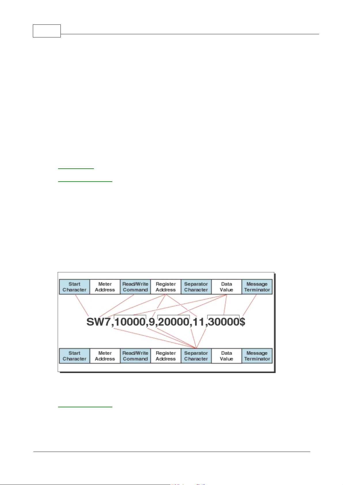
Zen Registers19
Examples
Description
SR$
Read
display
value, 50 milliseconds delay, all controllers respond.
s15r$
Read
display
value, 50 milliseconds delay, controller address 15 responds.
SR57*
Read
Peak
value, 2 milliseconds delay, all controllers respond.
Sr8194*
Read
Code 1
setting, 2 milliseconds delay, all controllers respond.
s2w1 -10000$
Write
-10000
to the display register of controller address 2, 50 milliseconds
delay.
SW16393 Chan_1$
Write ASCII text string
Chan_1
to channel 1 text register, 50 milliseconds.
s10w8206,7*
Change brightness to
7
on controller address 8206, 2 milliseconds delay.
See also
Multiple Write
ASCII Text Registers
This feature allows multiple registers to be written in a single ASCII command string. It is similar to a
normal write command with the following differences:
·
After the first data value, a separator character is inserted instead of the message terminator. Then
the next register address is specified, followed by another separator character and the next data
value. This procedure is repeated for each new register. The message terminator is added after the
last data value in the string.
·
Any number of registers can be written in the above manner provided the total length of the
command string does not exceed 73 ASCII characters, including spaces and message terminator.
Two examples of the multiple write command
See also
ASCII Text Registers
A macro is a set of commands that run automatically when the controller is powered up.
Define
Instruments Ltd.
has a growing library of macros to suit a wide range of customer applications.
Macros can be installed in the controller at the factory during initial programming or by the customer
1.4.1 ASCII Read/Write Examples
1.4.2 Multiple Write
1.5 Macro Compiling & Uploading
ZEN-16-REG-MAN-18V01
© <2018> ... Define Instruments Ltd.
Page 21

Introduction
at some later date. Macros are written by
Define Instruments Ltd.
or the customer using the
CodeLab
,
which is available for free download at
www.defineinstruments.com
.
20
ZEN-16-REG-MAN-18V01
© <2018> ... Define Instruments Ltd.
Page 22

Part
II
Page 23

2 Register List
The registers described in the topics of this Help are available for controller configuration and macro
programming purposes. Each register is identified in four ways, by:
Name
This is the name of the register and relates to its function.
Description
This describes the function of each register.
Symbol Type
Under Symbol Type, the following abbreviations identify the register type:
B_
The symbol B_ is followed by a number from 0 up to 31 and describes the
register bit number.
F_32
The symbol F_32 identifies the register as a floating point 32-bit register
(IEEE-754). (Modbus word order is Little Endian)
PF_32
The symbol PF_32 identifies the register as a pseudo floating point 32-bit
register (IEEE-754). (Modbus word order is Little Endian) (See
32-
bit Pseudo Floating Point (1537 to 2047)
).
SF_32
The symbol SF_32 identifies the register as a swapped floating point 32-bit
register (IEEE-754). When accessing via Modbus word order is Big Endian.
This register type was included to maintain backwards compatibility with older
Intech products.
_R
The symbol _R identifies the register as a read only register and may be
attached to another symbol. For example, B_0_R identifies this as bit 0 read
only.
S_
The symbol S_ is followed by either 16, 24, or 32, identifying the register as a
16, 24, or 32-bit signed integer.
U_
The symbol U_ is followed by either 8, 16, or 32 identifying the register as an
8, 16, or 32-bit unsigned integer.
O_
The symbol O_ is followed by either 8, 16, or 32 identifying the register as an
8, 16, or 32-bit unsigned integer which is displayed in an octal format.
_W
The symbol _W identifies the register as a write only register.
L_
The symbol _L identifies the register as a text string that contains printable
ASCII characters from 0x20 - 0x7a.
Register Number
This is the number that identifies the register in the controller.
See Also
Memory Types
The Zen16 Series controller incorporates a number of text registers for storage of ASCII text strings.
These strings vary in length from 8 to 62 characters depending on the intended function of the text
register. The USER_TEXT and TEXT_VARIABLE registers are intended for macro use to store user
text data.
Note: The table below is correct for F/W version 2.3.01 and following. On older versions most text
strings used for channel naming were only 14 chars long.
Text registers can be accessed in the ASCII serial mode via the serial port or from the Macro.
Name
Description
Symbol
Type
Register
Number
Memory
Type
Register List
22
2.1 ASCII Text Registers
ZEN-16-REG-MAN-18V01
© <2018> ... Define Instruments Ltd.
Page 24

Zen Registers23
DISPLAY_STRING
Write Display Text to primary display (for use
with serial port in ASCII mode)
L_100
16385
RAM
DISPLAY_STRING2
Write Display Text to second display (for use
with serial port in ASCII mode)
L_100
16387
RAM
DISPLAY_STRING3
Write Display Text to third display (for use with
serial port in ASCII mode)
L_100
16389
RAM
RESULT_TEXT
Text display for Result
L_30
16391
EEPROM
CHANNEL1_TEXT
Text display for Channel 1
L_30
16393
EEPROM
CHANNEL2_TEXT
Text display for Channel 2
L_30
16395
EEPROM
CHANNEL3_TEXT
Text display for Channel 3
L_30
16397
EEPROM
CHANNEL4_TEXT
Text display for Channel 4
L_30
16399
EEPROM
CHANNEL5_TEXT
Text display for Channel 5
L_30
16401
EEPROM
CHANNEL6_TEXT
Text display for Channel 6
L_30
16403
EEPROM
CHANNEL7_TEXT
Text display for Channel 7
L_30
16405
EEPROM
CHANNEL8_TEXT
Text display for Channel 8
L_30
16407
EEPROM
CHANNEL9_TEXT
Text display for Channel 9
L_30
16409
EEPROM
CHANNEL10_TEXT
Text display for Channel 10
L_30
16411
EEPROM
CHANNEL11_TEXT
Text display for Channel 11
L_30
16413
EEPROM
CHANNEL12_TEXT
Text display for Channel 12
L_30
16415
EEPROM
CHANNEL13_TEXT
Text display for Channel 13
L_30
16417
EEPROM
CHANNEL14_TEXT
Text display for Channel 14
L_30
16419
EEPROM
CHANNEL15_TEXT
Text display for Channel 15
L_30
16421
EEPROM
CHANNEL16_TEXT
Text display for Channel 16
L_30
16423
EEPROM
ZEN-16-REG-MAN-18V01
© <2018> ... Define Instruments Ltd.
Page 25

Register List
COUNTER_A_TEXT
Text display for Counter A
L_30
16427
EEPROM
COUNTER_B_TEXT
Text display for Counter B
L_30
16429
EEPROM
COUNTER_C_TEXT
Text display for Counter C
L_30
16431
EEPROM
COUNTER_D_TEXT
Text display for Counter D
L_30
16433
EEPROM
TOTAL1_TEXT
Text display for Totalizer 1
L_30
16437
EEPROM
TOTAL2_TEXT
Text display for Totalizer 2
L_30
16439
EEPROM
TOTAL3_TEXT
Text display for Totalizer 3
L_30
16441
EEPROM
TOTAL4_TEXT
Text display for Totalizer 4
L_30
16443
EEPROM
TOTAL5_TEXT
Text display for Totalizer 5
L_30
16445
EEPROM
TOTAL6_TEXT
Text display for Totalizer 6
L_30
16447
EEPROM
TOTAL7_TEXT
Text display for Totalizer 7
L_30
16449
EEPROM
TOTAL8_TEXT
Text display for Totalizer 8
L_30
16451
EEPROM
TOTAL9_TEXT
Text display for Totalizer 9
L_30
16453
EEPROM
TOTAL10_TEXT
Text display for Totalizer 10
L_30
16455
EEPROM
AUX1_TEXT
Text display for Auxiliary 1
L_30
16463
EEPROM
AUX2_TEXT
Text display for Auxiliary 2
L_30
16465
16463
EEPROM
AUX3_TEXT
Text display for Auxiliary 3
L_30
16467
16463
EEPROM
AUX4_TEXT
Text display for Auxiliary 4
L_30
16469
16463
EEPROM
AUX5_TEXT
Text display for Auxiliary 5
L_30
16471
EEPROM
AUX6_TEXT
Text display for Auxiliary 6
L_30
16473
EEPROM
AUX7_TEXT
Text display for Auxiliary 7
L_30
16475
EEPROM
AUX8_TEXT
Text display for Auxiliary 8
L_30
16477
EEPROM
AUX9_TEXT
Text display for Auxiliary 9
L_30
16479
EEPROM
AUX10_TEXT
Text display for Auxiliary 10
L_30
16481
EEPROM
AUX11_TEXT
Text display for Auxiliary 11
L_30
16483
EEPROM
AUX12_TEXT
Text display for Auxiliary 12
L_30
16485
EEPROM
AUX13_TEXT
Text display for Auxiliary 13
L_30
16487
EEPROM
AUX14_TEXT
Text display for Auxiliary 14
L_30
16489
EEPROM
AUX15_TEXT
Text display for Auxiliary 15
L_30
16491
EEPROM
AUX16_TEXT
Text display for Auxiliary 16
L_30
16493
EEPROM
SETPOINT1_TEXT
Text display for Setpoint 1
L_30
16495
EEPROM
SETPOINT2_TEXT
Text display for Setpoint 2
L_30
16497
EEPROM
SETPOINT3_TEXT
Text display for Setpoint 3
L_30
16499
EEPROM
SETPOINT4_TEXT
Text display for Setpoint 4
L_30
16501
EEPROM
SETPOINT5_TEXT
Text display for Setpoint 5
L_30
16503
EEPROM
SETPOINT6_TEXT
Text display for Setpoint 6
L_30
16505
EEPROM
SETPOINT7_TEXT
Text display for Setpoint 7
L_30
16507
EEPROM
SETPOINT8_TEXT
Text display for Setpoint 8
L_30
16509
EEPROM
SETPOINT9_TEXT
Text display for Setpoint 9
L_30
16511
EEPROM
SETPOINT10_TEXT
Text display for Setpoint 10
L_30
16513
EEPROM
SETPOINT11_TEXT
Text display for Setpoint 11
L_30
16515
EEPROM
SETPOINT12_TEXT
Text display for Setpoint 12
L_30
16517
EEPROM
24
ZEN-16-REG-MAN-18V01
© <2018> ... Define Instruments Ltd.
Page 26

Zen Registers25
PEAK1_TEXT
Text display for Peak
L_30
16527
EEPROM
VALLEY1_TEXT
Text display for Valley
L_30
16529
EEPROM
PEAK2_TEXT
Text display for Peak 2
L_30
16531
EEPROM
VALLEY2_TEXT
Text display for Valley 2
L_30
16533
EEPROM
PEAK3_TEXT
Text display for Peak 3
L_30
16535
EEPROM
VALLEY3_TEXT
Text display for Valley 3
L_30
16537
EEPROM
OVER_TEXT
Text display for over range
L_14
16539
EEPROM
UNDER_TEXT
Text display for under range
L_14
16541
EEPROM
PRINT_STRING
Print String
L_62
16543
EEPROM
STARTUP_TEXT_LINE1
Non-volatile 16 character text string for user
defined startup text on line 1 (1602 LCD display
only). L_16
16545
EEPROM
STARTUP_TEXT_LINE2
Non-volatile 16 character text string for user
defined startup text on line 2 (1602 LCD
display).
L_16
16547
EEPROM
SINGLE_LOG
This register reads or write a single data log
sample if data logging is enabled.
L_14
16553
EEPROM
METER_TYPE
L_14_R
16565
FLASH
USER_TEXT 1
to
USER_TEXT64
Are all non-volatile 30 character text strings for
user defined text storage, using only odd number
register addresses from 16567 to 16693.
L_30
16567
to
16693
EEPROM
TEXT_VARIABLE1
30 character text string variable in RAM.
L_30 16897
RAM
TEXT_VARIABLE2
30 character text string variable in RAM.
L_30
16899
RAM
TEXT_VARIABLE3
30 character text string variable in RAM.
L_30
16901
RAM
TEXT_VARIABLE4
30 character text string variable in RAM.
L_30
16903
RAM
TEXT_VARIABLE5
30 character text string variable in RAM.
L_30
16905
RAM
TEXT_VARIABLE6
30 character text string variable in RAM.
L_30
16907
RAM
TEXT_VARIABLE7
30 character text string variable in RAM.
L_30
16909
RAM
TEXT_VARIABLE8
30 character text string variable in RAM.
L_30
16911
RAM
TEXT_VARIABLE9
30 character text string variable in RAM.
L_30
16913
RAM
TEXT_VARIABLE10
30 character text string variable in RAM.
L_30
16915
RAM
TEXT_VARIABLE11
30 character text string variable in RAM.
L_30
16917
RAM
TEXT_VARIABLE12
30 character text string variable in RAM.
L_30
16919
RAM
TEXT_VARIABLE13
30 character text string variable in RAM.
L_30
16921
RAM
TEXT_VARIABLE14
30 character text string variable in RAM.
L_30
16923
RAM
TEXT_VARIABLE15
30 character text string variable in RAM.
L_30
16925
RAM
TEXT_VARIABLE16
30 character text string variable in RAM.
L_30
16927
RAM
See also
Register 16385
ASCII Characters for 14-segment
Print String - Register 16543
Registers 16385 to 16389 are used to write a text string directly to the controller display via the serial
port in ASCII mode. Text strings are only displayed while the controller is in it's normal operating
mode, known as the
operational display
. Text strings are ignored when the controller is in any edit
or view mode.
A scrolling text string of up to 100 characters long can be sent to the display. The string is scrolled
2.1.1 Register 16385, 16387, 16389
ZEN-16-REG-MAN-18V01
© <2018> ... Define Instruments Ltd.
Page 27

through once and then the display returns to the operational display. The special ~ (tilde) character is
used to insert an instantaneous register value into the text string.
See note on register 16543
(print
string) for more information on this feature.
To send text to the primary display, the following commands can be used:
This Text String
Displays This
SW16385
This text string scrolls across the display_____ *
SW16385
Setpoint 1 = ~6 Volts $
Register 16385 is available on all models of
Zen16
Series controllers. Registers 16387 and 16389 are
also available on controller versions that have multiple displays (such as the DI-602, DI-802, DI-503,
etc.) A write to register 16387 scrolls a text message on the second line of the display and a write to
register 16389 scrolls a message on the third line of the display.
A read of registers 16385 to 16389 results in the text
DISP
being displayed.
2.1.2 ASCII Characters for 14-Segment Display
The following characters can be selected for the last digit by selecting
and entering the appropriate register control value.
Character
Register Control
Value (decimal)
Character
Register Control
Value (decimal)
Space
32
@ 64!33A65"34B66#35C67$36D68%37E69&38F70'39G71(40H72)41I73*42J74+43K75,44L76-45M77.46N78/47O79048P80149Q81250R82351S83452T84553U85654V86755W87856X88
Register List
26
ZEN-16-REG-MAN-18V01
© <2018> ... Define Instruments Ltd.
Page 28

Zen Registers27
957Y89:58(displays as decimal
point)Z90;59[91
(displays same as
C)<60\92=61]93>62^94?63_
95
When setup in the print mode, the controller can print data from any register directly to a serial
printer, or to a PC where it can be imported into a spreadsheet.
Register 16543 is a special register that allows you to specify the text and data stored in specific
registers to be printed out when a print command is issued by the controller while in the print mode.
Through the serial port, register 16543 can be either written to or read from using a terminal program
on a PC.
Writing To Register 16543
Writing to register 16543 tells the controller to print the data stored in one or more of the controller's
registers when the print command is issued. To get the controller to print, the printer must be
connected to the controller through the serial port and the controller must be programmed to run in
the
print mode
. The data to be printed depends on how the controller has been programmed.
For example, to display a flow rate and total. The total length of a write string can be up to 62 ASCII
characters long. See Printing Restrictions.
Reading From Register 16543
Reading from register 16543 allows you to check your settings prior to removing the PC from the
serial port and connecting to a printer. Register 16543 can be read in the normal manner: SR16543$.
Example of Writing To Register 16543
The following example shows a write to register 16543 with the controller setup to display flow rate
and total flow of channel 1.
swx Rate = ~1
(add carriage return and line feed)
Total = ~37$
The above write to register 16543 means the following:
sw16543
:
Start writing to register 16543.
Rate =
:
Tells the controller to print the word Rate =.
~1:Tells the controller to print the current flow rate (display data), held in register
1, after the word Rate =.
Total =
:
Tells the controller to print the word Total =.
~37:Tells the controller to print the current total flow (stored data), held in register
37, after the word Flow =.
The printer would then print, for example, the following:
Rate = 2000
Total = 25000
This means that the current flow rate is 2000 and the total flow at this point is 25000.
2.1.3 Print String - Register 16543
ZEN-16-REG-MAN-18V01
© <2018> ... Define Instruments Ltd.
Page 29

Register List
Example of Reading From Register 16543
Having written the above example to the controller, to check the contents of register 16543 using the
terminal program through the PC, type the following:
sr16543$
The following is shown on the PC screen:
Rate = ~1
Total = ~37$
Printing Restrictions
When printing, any alphanumeric ASCII character can be used within the following restrictions:
·
The
$
and
*
characters are reserved for the terminating character at the end of the string and
cannot be used as part of the text string.
·
The total string length must be no greater than 62 bytes long. This includes spaces, tabs, carriage
returns, line feeds, and the terminating character. There must be a separator space between the
register address 16543 and the start of the string.
Note, this separator space does not have to
be included in text string length calculations
.·Any number following a
~
(tilde) character is interpreted as a register address. During a printout the
register's current value is printed out in this position.
·
The ASCII character
\
is treated as a special character in the print string. When a
\
is encountered,
a * is printed in its place (
*
is reserved as a terminating character and normally can not appear
anywhere in the text string). This allows the print output of one controller to be connected to another
controller that is operating in the ASCII mode.
For example, if the print string reads:
swx sw3 ~11\ sw4 ~13\ sw6 ~1\$
The printer prints the following:
sw3
(current register value)
* sw4
(current register value)
*
sw6
(current register value)
*
Up to seven different registers can be specified in one text string, provided that the total string length
is no greater than 62 bytes long and the total length of the resulting printout is less than 100 bytes
long (including time stamp if selected).
For example, the following tab delimited output could be specified to input display data, processed
result, processed channel 1, processed channel 2, peak, valley, and total, directly into a spreadsheet:
swx ~1(tab)~7(tab)~9(tab)~11(tab)~57(tab)~59(tab)~37$
When calculating the length of the printout, an allowance of 7 bytes for each register address should
be used, plus any extra text or separating characters such as tabs or spaces.
NOTE
: As a new line is usually represented by a carriage return and a line feed, 2 bytes should be
added for each new line in text string length calculations.
The
Zen16
controller can have up to 16 analog input modules fitted. These can be configured for a
variety of different input sensors including RTD temperature probes, thermocouple temperature
probes, voltage and current measurement and counters. Input modules can be isolated or non-
isolated types. Each type of input module will have different setup and configuration requirements
which need to be adhered to for correct functionality.
28
2.2 Analog Inputs
ZEN-16-REG-MAN-18V01
© <2018> ... Define Instruments Ltd.
Page 30

Zen Registers29
However, regardless of which type of input module is fitted, the
Zen16
main controller will poll all
input modules and create an updated copy of the result and status registers of each input module.
This data is then scaled and becomes available in the analog result registers shown in this section.
This section also shows the various configuration registers associated with the result data.
NOTE: The configuration of each input module must be done separately via the index register 8224.
Channel 1 registers can be selected as the data source for:
·
The primary display.
·
The second display, if installed.
·
The third display, if installed.
·
Trigger for advanced setpoints SP1 to SP16 (integer registers only)
·
Analogue output channels (integer registers only).
·
Setpoint reset destination (integer registers only).
The reset destination mode allows you to select a register to be reset using the contents of another
register triggered by a setpoint.
Name
Description
Symbol
Type
Register
Number
Memory
Type
CH1
32-bit register that holds the processed data for CH1.
S_32
645
RAM/FLASH
CH1_RAW
32-bit register that holds the raw data for CH1.
Note
: When input module is operating in counter mode,
this register shows the raw accumulated count value.
S_32
677
RAM/FLASH
CH1_FLOAT
32-bit register that holds the CH1 data in a floating
point format. Scaling and decimal point values are
based on those used for the CH1 data shown above.
F_32
1193
RAM
CH1_SWAPPED_FLOAT
32-bit register that holds the CH1 data in a floating
point format. Scaling and decimal point values are
based on those used for the CH1 data shown above.
Note
: This register is used to maintain backwards
compatibility with older Intech products. When reading
this register via Modbus the word order is Big Endian.
SF_32
17
RAM
CH1_12
12-bit register that holds the processed data for CH1.
(Range from 0 - 4095) This register is used to maintain
backwards compatibility with older Intech products.
U_121RAM
IM_STATUS1
16-bit unsigned register that holds the input module
status for CH1. (See
Input Module Status
)
U_16
4592
RAM
The above registers are normally updated by the operating system of the controller after a new input
sample is processed. If the channel is disabled or in a counter mode, it is also possible to modify the
contents of the register by writing to it from the setpoint reset logic, from the Macro, or via the serial
port. A write to these registers in any other operational mode may result in the newly written value
being overwritten by the operating system in the controller.
See also
CH1 Setup Registers
2.2.1 Channel 1
ZEN-16-REG-MAN-18V01
© <2018> ... Define Instruments Ltd.
Page 31

2.2.1.1 CH1 Setup Registers
Name
Description
Symbol
Type
Register
Number
Memory Type
OFFSET_CH1
32-bit register. Holds the calibration offset for
CH1 and CH1_FLOAT.
S_32
613
RAM/EEPROM
SCALE_FACTOR_CH1
32-bit floating point register. Holds the
calibration scale factor for CH1 and
CH1_FLOAT.
F_32
1097
RAM/EEPROM
OFFSET_CH1_12BIT
16-bit register. Holds the calibration offset for
CH1_12.
S_16
4576
RAM/EEPROM
SCALE_FACTOR_CH1_12BIT
32-bit floating point register. Holds the
calibration scale factor for CH1_12.
F_32
1161
RAM/EEPROM
CHANNEL1_TEXT
Text display for CH1.
L_30
16393
EEROM
UNITS_TEXT_CH1
Units text for CH1. (Note: this is a storage
register used by external applications. It is not
shown on the standard display.)
L_14
17409
EEROM
DISPLAY_FORMAT_CH1
8-bit register. Controls the display format
settings for CH1 (displayed in
octal
format).
O_8
8321
RAM/EEPROM
TEXT_CHARACTER_CH1
8-bit register. Holds the ASCII value for the last
digit text character for CH1 (0 = no character).
U_8
8375
RAM/EEPROM
See also
Channel 1
Zen16 controllers running firmware version V2.3.01 onwards also provide secondary result registers
for use with certain input modules.
The table below shows all registers associated with the secondary result values.
Name
Description
Symbol
Type
Register
Number
Memory Type
CH1_SEC_RESULT
32-bit register. Holds the scaled value for the
Ch1 secondary result.
S_32
737
RAM
CH1_SEC_RAW
32-bit register. Holds the scaled value for the
Ch1 secondary result.
S_32
771
RAM
CH1_SEC_FLOAT
32-bit pseudo float register. Holds the scaled
floating point result value for the Ch1 secondary
result. (See
32-
bit Pseudo Floating Point (1537 to 2047)
F_32
2017
RAM
OFFSET_CH1_12BIT
16-bit register. Holds the calibration offset for
CH1 secondary value and the CH1 12 bit offset.
S_16
4576
RAM/EEPROM
SCALE_FACTOR_CH1_12BIT
32-bit floating point register. Holds the
calibration scale factor for the CH1 secondary
value and CH1_12 bit value.
F_32
1161
RAM/EEPROM
CHANNEL1_SEC_TEXT
Text display for name of CH1 secondary result.
L_30
16929
EEROM
UNITS_TEXT_CH1_SEC
Units text for CH1 secondary result. (Note: this
is a storage register used by external
applications. It is not shown on the standard
display.)
L_14
17501
EEROM
DISPLAY_FORMAT_CH1_SEC
8-bit register. Controls the display format
settings for CH1 secondary result value
(displayed in
octal
format).
O_8
8544
RAM/EEPROM
See also
Channel 1
CH1 Setup Registers
Register List
30
2.2.1.2 CH1 Secondary Result
ZEN-16-REG-MAN-18V01
© <2018> ... Define Instruments Ltd.
Page 32

Zen Registers31
Channel 2 registers can be selected as the data source for:
·
The primary display.
·
The second display, if installed.
·
The third display, if installed.
·
Trigger for advanced setpoints SP1 to SP16 (integer registers only)
·
Analogue output channels (integer registers only).
·
Setpoint reset destination (integer registers only).
The reset destination mode allows you to select a register to be reset using the contents of another
register triggered by a setpoint.
Name
Description
Symbol
Type
Register
Number
Memory
Type
CH2
32-bit register that holds the processed data for CH2.
S_32
647
RAM/FLASH
CH2_RAW
32-bit register that holds the raw data for CH2.
Note
: When input module is operating in counter mode,
this register shows the raw accumulated count value.
S_32
679
RAM/FLASH
CH2_FLOAT
32-bit register that holds the CH2 data in a floating
point format. Scaling and decimal point values are
based on those used for the CH2 data shown above.
F_32
1195
RAM
CH2_SWAPPED_FLOAT
32-bit register that holds the CH2 data in a floating
point format. Scaling and decimal point values are
based on those used for the CH2 data shown above.
Note
:This register is used to maintain backwards
compatibility with older Intech products. When reading
this register via Modbus the word order is Big Endian.
SF_32
19
RAM
CH2_12
12-bit register that holds the processed data for CH2.
(Range from 0 - 4095) This register is used to maintain
backwards compatibility with older Intech products.
U_122RAM
IM_STATUS2
16-bit unsigned register that holds the input module
status for CH2. (See
Input Module Status
)
U_16
4593
RAM
The above registers are normally updated by the operating system of the controller after a new input
sample is processed. If the channel is disabled or in a counter mode, it is also possible to modify the
contents of the register by writing to it from the setpoint reset logic, from the Macro, or via the serial
port. A write to these registers in any other operational mode may result in the newly written value
being overwritten by the operating system in the controller.
See also
CH2 Setup Registers
Name
Description
Symbol
Type
Register
Number
Memory Type
OFFSET_CH2
32-bit register. Holds the calibration offset for
CH2 and CH2_FLOAT.
S_32
615
RAM/EEPROM
SCALE_FACTOR_CH2
32-bit floating point register. Holds the
calibration scale factor for CH2 and
CH2_FLOAT.
F_32
1099
RAM/EEPROM
OFFSET_CH2_12BIT
16-bit register. Holds the calibration offset for
CH2_12.
S_16
4577
RAM/EEPROM
SCALE_FACTOR_CH2_12BIT
32-bit floating point register. Holds the
calibration scale factor for CH2_12.
F_32
1163
RAM/EEPROM
2.2.2 Channel 2
2.2.2.1 CH2 Setup Registers
ZEN-16-REG-MAN-18V01
© <2018> ... Define Instruments Ltd.
Page 33

CHANNEL2_TEXT
Text display for CH2.
L_30
16395
EEROM
UNITS_TEXT_CH2
Units text for CH2. (Note: this is a storage
register used by external applications. It is not
shown on the standard display.)
L_14
17411
EEROM
DISPLAY_FORMAT_CH2
8-bit register. Controls the display format
settings for CH2 (displayed in
octal
format).
O_8
8322
RAM/EEPROM
TEXT_CHARACTER_CH2
8-bit register. Holds the ASCII value for the last
digit text character for CH2 (0 = no character).
U_8
8376
RAM/EEPROM
See also
Channel 2
2.2.2.2 CH2 Secondary Result
Zen16 controllers running firmware version V2.3.01 onwards also provide secondary result registers
for use with certain input modules.
The table below shows all registers associated with the secondary result values.
Name
Description
Symbol
Type
Register
Number
Memory Type
CH2_SEC_RESULT
32-bit register. Holds the scaled value for the
Ch2 secondary result.
S_32
739
RAM
CH2_SEC_RAW
32-bit register. Holds the scaled value for the
Ch2 secondary result.
S_32
773
RAM
CH2_SEC_FLOAT
32-bit pseudo float register. Holds the scaled
floating point result value for the Ch2 secondary
result. (See
32-
bit Pseudo Floating Point (1537 to 2047)
F_32
2019
RAM
OFFSET_CH2_12BIT
16-bit register. Holds the calibration offset for
CH2 secondary value and the CH2 12 bit offset.
S_16
4577
RAM/EEPROM
SCALE_FACTOR_CH2_12BIT
32-bit floating point register. Holds the
calibration scale factor for the CH2 secondary
value and CH2_12 bit value.
F_32
1163
RAM/EEPROM
CHANNEL2_SEC_TEXT
Text display for name of CH2 secondary result.
L_30
16931
EEROM
UNITS_TEXT_CH2_SEC
Units text for CH2 secondary result. (Note: this
is a storage register used by external
applications. It is not shown on the standard
display.)
L_14
17503
EEROM
DISPLAY_FORMAT_CH2_SEC
8-bit register. Controls the display format
settings for CH2 secondary result value
(displayed in
octal
format).
O_8
8545
RAM/EEPROM
See also
Channel 2
CH2 Setup Registers
Channel 3 registers can be selected as the data source for:
·
The primary display.
·
The second display, if installed.
·
The third display, if installed.
·
Trigger for advanced setpoints SP1 to SP16 (integer registers only)
·
Analogue output channels (integer registers only).
·
Setpoint reset destination (integer registers only).
The reset destination mode allows you to select a register to be reset using the contents of another
register triggered by a setpoint.
Register List
32
2.2.3 Channel 3
ZEN-16-REG-MAN-18V01
© <2018> ... Define Instruments Ltd.
Page 34

Zen Registers33
Name
Description
Symbol
Type
Register
Number
Memory
Type
CH3
32-bit register that holds the processed data for CH3.
S_32
649
RAM/FLASH
CH3_RAW
32-bit register that holds the raw data for CH3.
Note
: When input module is operating in counter mode,
this register shows the raw accumulated count value.
S_32
681
RAM/FLASH
CH3_FLOAT
32-bit register that holds the CH3 data in a floating
point format. Scaling and decimal point values are
based on those used for the CH3 data shown above.
F_32
1197
RAM
CH3_SWAPPED_FLOAT
32-bit register that holds the CH3 data in a floating
point format. Scaling and decimal point values are
based on those used for the CH3 data shown above.
Note
: This register is used to maintain backwards
compatibility with older Intech products. When reading
this register via Modbus the word order is Big Endian.
SF_32
21
RAM
CH3_12
12-bit register that holds the processed data for CH3.
(Range from 0 - 4095) This register is used to maintain
backwards compatibility with older Intech products.
U_123RAM
IM_STATUS3
16-bit unsigned register that holds the input module
status for CH3. (See
Input Module Status
)
U_16
4594
RAM
The above registers are normally updated by the operating system of the controller after a new input
sample is processed. If the channel is disabled or in a counter mode, it is also possible to modify the
contents of the register by writing to it from the setpoint reset logic, from the Macro, or via the serial
port. A write to these registers in any other operational mode may result in the newly written value
being overwritten by the operating system in the controller.
See also
CH3 Setup Registers
Name
Description
Symbol
Type
Register
Number
Memory Type
OFFSET_CH3
32-bit register. Holds the calibration offset for
CH3 and CH3_FLOAT.
S_32
617
RAM/EEPROM
SCALE_FACTOR_CH3
32-bit floating point register. Holds the
calibration scale factor for CH3 and
CH3_FLOAT.
F_32
1101
RAM/EEPROM
OFFSET_CH3_12BIT
16-bit register. Holds the calibration offset for
CH3_12.
S_16
4578
RAM/EEPROM
SCALE_FACTOR_CH3_12BIT
32-bit floating point register. Holds the
calibration scale factor for CH3_12.
F_32
1165
RAM/EEPROM
CHANNEL3_TEXT
Text display for CH3.
L_30
16397
EEROM
UNITS_TEXT_CH3
Units text for CH3. (Note: this is a storage
register used by external applications. It is not
shown on the standard display.)
L_14
17413
EEROM
DISPLAY_FORMAT_CH3
8-bit register. Controls the display format
settings for CH3 (displayed in
octal
format).
O_8
8323
RAM/EEPROM
TEXT_CHARACTER_CH3
8-bit register. Holds the ASCII value for the last
digit text character for CH3 (0 = no character).
U_8
8377
RAM/EEPROM
See also
Channel 3
Zen16 controllers running firmware version V2.3.01 onwards also provide secondary result registers
for use with certain input modules.
2.2.3.1 CH3 Setup Registers
2.2.3.2 CH3 Secondary Result
ZEN-16-REG-MAN-18V01
© <2018> ... Define Instruments Ltd.
Page 35

Register List
The table below shows all registers associated with the secondary result values.
Name
Description
Symbol
Type
Register
Number
Memory Type
CH3_SEC_RESULT
32-bit register. Holds the scaled value for the
Ch3 secondary result.
S_32
741
RAM
CH3_SEC_RAW
32-bit register. Holds the scaled value for the
Ch3 secondary result.
S_32
775
RAM
CH3_SEC_FLOAT
32-bit pseudo float register. Holds the scaled
floating point result value for the Ch3 secondary
result. (See
32-
bit Pseudo Floating Point (1537 to 2047)
F_32
2021
RAM
OFFSET_CH3_12BIT
16-bit register. Holds the calibration offset for
CH3 secondary value and the CH3 12 bit offset.
S_16
4578
RAM/EEPROM
SCALE_FACTOR_CH3_12BIT
32-bit floating point register. Holds the
calibration scale factor for the CH3 secondary
value and CH3_12 bit value.
F_32
1165
RAM/EEPROM
CHANNEL3_SEC_TEXT
Text display for name of CH3 secondary result.
L_30
16933
EEROM
UNITS_TEXT_CH3_SEC
Units text for CH3 secondary result. (Note: this
is a storage register used by external
applications. It is not shown on the standard
display.)
L_14
17505
EEROM
DISPLAY_FORMAT_CH3_SEC
8-bit register. Controls the display format
settings for CH3 secondary result value
(displayed in
octal
format).
O_8
8546
RAM/EEPROM
See also
Channel 3
CH3 Setup Registers
Channel 4 registers can be selected as the data source for:
·
The primary display.
·
The second display, if installed.
·
The third display, if installed.
·
Trigger for advanced setpoints SP1 to SP16 (integer registers only)
·
Analogue output channels (integer registers only).
·
Setpoint reset destination (integer registers only).
The reset destination mode allows you to select a register to be reset using the contents of another
register triggered by a setpoint.
Name
Description
Symbol
Type
Register
Number
Memory
Type
CH4
32-bit register that holds the processed data for CH4.
S_32
651
RAM/FLASH
CH4_RAW
32-bit register that holds the raw data for CH4.
Note
: When input module is operating in counter mode,
this register shows the raw accumulated count value.
S_32
683
RAM/FLASH
CH4_FLOAT
32-bit register that holds the CH4 data in a floating
point format. Scaling and decimal point values are
based on those used for the CH4 data shown above.
F_32
1199
RAM
34
2.2.4 Channel 4
ZEN-16-REG-MAN-18V01
© <2018> ... Define Instruments Ltd.
Page 36

Zen Registers35
CH4_SWAPPED_FLOAT
32-bit register that holds the CH4 data in a floating
point format. Scaling and decimal point values are
based on those used for the CH4 data shown above.
Note
:This register is used to maintain backwards
compatibility with older Intech products. When reading
this register via Modbus the word order is Big Endian.
SF_32
23
RAM
CH4_12
12-bit register that holds the processed data for CH4.
(Range from 0 - 4095) This register is used to maintain
backwards compatibility with older Intech products.
U_124RAM
IM_STATUS4
16-bit unsigned register that holds the input module
status for CH4. (See
Input Module Status
)
U_16
4595
RAM
The above registers are normally updated by the operating system of the controller after a new input
sample is processed. If the channel is disabled or in a counter mode, it is also possible to modify the
contents of the register by writing to it from the setpoint reset logic, from the Macro, or via the serial
port. A write to these registers in any other operational mode may result in the newly written value
being overwritten by the operating system in the controller.
See also
CH4 Setup Registers
Name
Description
Symbol
Type
Register
Number
Memory Type
OFFSET_CH4
32-bit register. Holds the calibration offset for
CH4 and CH4_FLOAT.
S_32
619
RAM/EEPROM
SCALE_FACTOR_CH4
32-bit floating point register. Holds the
calibration scale factor for CH4 and
CH4_FLOAT.
F_32
1103
RAM/EEPROM
OFFSET_CH4_12BIT
16-bit register. Holds the calibration offset for
CH4_12.
S_16
4579
RAM/EEPROM
SCALE_FACTOR_CH4_12BIT
32-bit floating point register. Holds the
calibration scale factor for CH4_12.
F_32
1167
RAM/EEPROM
CHANNEL4_TEXT
Text display for CH4.
L_30
16399
EEROM
UNITS_TEXT_CH4
Units text for CH4. (Note: this is a storage
register used by external applications. It is not
shown on the standard display.)
L_14
17415
EEROM
DISPLAY_FORMAT_CH4
8-bit register. Controls the display format
settings for CH4 (displayed in
octal
format).
O_8
8324
RAM/EEPROM
TEXT_CHARACTER_CH4
8-bit register. Holds the ASCII value for the last
digit text character for CH4 (0 = no character).
U_8
8378
RAM/EEPROM
See also
Channel 4
Zen16 controllers running firmware version V2.3.01 onwards also provide secondary result registers
for use with certain input modules.
The table below shows all registers associated with the secondary result values.
2.2.4.1 CH4 Setup Registers
2.2.4.2 CH4 Secondary Result
ZEN-16-REG-MAN-18V01
© <2018> ... Define Instruments Ltd.
Page 37

Register List
Name
Description
Symbol
Type
Register
Number
Memory Type
CH4_SEC_RESULT
32-bit register. Holds the scaled value for the
Ch4 secondary result.
S_32
743
RAM
CH4_SEC_RAW
32-bit register. Holds the scaled value for the
Ch4 secondary result.
S_32
777
RAM
CH4_SEC_FLOAT
32-bit pseudo float register. Holds the scaled
floating point result value for the Ch4 secondary
result. (See
32-
bit Pseudo Floating Point (1537 to 2047)
F_32
2023
RAM
OFFSET_CH4_12BIT
16-bit register. Holds the calibration offset for
CH4 secondary value and the CH4 12 bit offset.
S_16
4579
RAM/EEPROM
SCALE_FACTOR_CH4_12BIT
32-bit floating point register. Holds the
calibration scale factor for the CH4 secondary
value and CH4_12 bit value.
F_32
1167
RAM/EEPROM
CHANNEL4_SEC_TEXT
Text display for name of CH4 secondary result.
L_30
16935
EEROM
UNITS_TEXT_CH4_SEC
Units text for CH4 secondary result. (Note: this
is a storage register used by external
applications. It is not shown on the standard
display.)
L_14
17507
EEROM
DISPLAY_FORMAT_CH4_SEC
8-bit register. Controls the display format
settings for CH4 secondary result value
(displayed in
octal
format).
O_8
8547
RAM/EEPROM
See also
Channel 4
CH4 Setup Registers
Channel 5 registers can be selected as the data source for:
·
The primary display.
·
The second display, if installed.
·
The third display, if installed.
·
Trigger for advanced setpoints SP1 to SP16 (integer registers only)
·
Analogue output channels (integer registers only).
·
Setpoint reset destination (integer registers only).
The reset destination mode allows you to select a register to be reset using the contents of another
register triggered by a setpoint.
Name
Description
Symbol
Type
Register
Number
Memory
Type
CH5
32-bit register that holds the processed data for CH5.
S_32
653
RAM/FLASH
CH5_RAW
32-bit register that holds the raw data for CH5.
Note
: When input module is operating in counter mode,
this register shows the raw accumulated count value.
S_32
685
RAM/FLASH
CH5_FLOAT
32-bit register that holds the CH5 data in a floating
point format. Scaling and decimal point values are
based on those used for the CH5 data shown above.
F_32
1201
RAM
36
2.2.5 Channel 5
ZEN-16-REG-MAN-18V01
© <2018> ... Define Instruments Ltd.
Page 38

Zen Registers37
CH5_SWAPPED_FLOAT
32-bit register that holds the CH5 data in a floating
point format. Scaling and decimal point values are
based on those used for the CH5 data shown above.
Note
: This register is used to maintain backwards
compatibility with older Intech products. When reading
this register via Modbus the word order is Big Endian.
SF_32
25
CH5_12
12-bit register that holds the processed data for CH5.
(Range from 0 - 4095) This register is used to maintain
backwards compatibility with older Intech products.
U_125RAM
IM_STATUS5
16-bit unsigned register that holds the input module
status for CH5. (See
Input Module Status
)
U_16
4596
RAM
The above registers are normally updated by the operating system of the controller after a new input
sample is processed. If the channel is disabled or in a counter mode, it is also possible to modify the
contents of the register by writing to it from the setpoint reset logic, from the Macro, or via the serial
port. A write to these registers in any other operational mode may result in the newly written value
being overwritten by the operating system in the controller.
See also
CH5 Setup Registers
Name
Description
Symbol
Type
Register
Number
Memory Type
OFFSET_CH5
32-bit register. Holds the calibration offset for
CH5 and CH5_FLOAT.
S_32
621
RAM/EEPROM
SCALE_FACTOR_CH5
32-bit floating point register. Holds the
calibration scale factor for CH5 and
CH5_FLOAT.
F_32
1105
RAM/EEPROM
OFFSET_CH5_12BIT
16-bit register. Holds the calibration offset for
CH5_12.
S_16
4580
RAM/EEPROM
SCALE_FACTOR_CH5_12BIT
32-bit floating point register. Holds the
calibration scale factor for CH5_12.
F_32
1169
RAM/EEPROM
CHANNEL5_TEXT
Text display for CH5.
L_30
16401
EEROM
UNITS_TEXT_CH5
Units text for CH5. (Note: this is a storage
register used by external applications. It is not
shown on the standard display.)
L_14
17417
EEROM
DISPLAY_FORMAT_CH5
8-bit register. Controls the display format
settings for CH5 (displayed in
octal
format).
O_8
8325
RAM/EEPROM
TEXT_CHARACTER_CH5
8-bit register. Holds the ASCII value for the last
digit text character for CH5 (0 = no character).
U_8
8379
RAM/EEPROM
See also
Channel 5
Zen16 controllers running firmware version V2.3.01 onwards also provide secondary result registers
for use with certain input modules.
The table below shows all registers associated with the secondary result values.
2.2.5.1 CH5 Setup Registers
2.2.5.2 CH5 Secondary Result
ZEN-16-REG-MAN-18V01
© <2018> ... Define Instruments Ltd.
Page 39

Register List
Name
Description
Symbol
Type
Register
Number
Memory Type
CH5_SEC_RESULT
32-bit register. Holds the scaled value for the
Ch5 secondary result.
S_32
745
RAM
CH5_SEC_RAW
32-bit register. Holds the scaled value for the
Ch5 secondary result.
S_32
779
RAM
CH5_SEC_FLOAT
32-bit pseudo float register. Holds the scaled
floating point result value for the Ch5 secondary
result. (See
32-
bit Pseudo Floating Point (1537 to 2047)
F_32
2025
RAM
OFFSET_CH5_12BIT
16-bit register. Holds the calibration offset for
CH5 secondary value and the CH5 12 bit offset.
S_16
4580
RAM/EEPROM
SCALE_FACTOR_CH5_12BIT
32-bit floating point register. Holds the
calibration scale factor for the CH5 secondary
value and CH5_12 bit value.
F_32
1169
RAM/EEPROM
CHANNEL5_SEC_TEXT
Text display for name of CH5 secondary result.
L_30
16937
EEROM
UNITS_TEXT_CH5_SEC
Units text for CH5 secondary result. (Note: this
is a storage register used by external
applications. It is not shown on the standard
display.)
L_14
17509
EEROM
DISPLAY_FORMAT_CH5_SEC
8-bit register. Controls the display format
settings for CH5 secondary result value
(displayed in
octal
format).
O_8
8548
RAM/EEPROM
See also
Channel 5
CH5 Setup Registers
Channel 6 registers can be selected as the data source for:
·
The primary display.
·
The second display, if installed.
·
The third display, if installed.
·
Trigger for advanced setpoints SP1 to SP16 (integer registers only)
·
Analogue output channels (integer registers only).
·
Setpoint reset destination (integer registers only).
The reset destination mode allows you to select a register to be reset using the contents of another
register triggered by a setpoint.
Name
Description
Symbol
Type
Register
Number
Memory
Type
CH6
32-bit register that holds the processed data for CH6.
S_32
655
RAM/FLASH
CH6_RAW
32-bit register that holds the raw data for CH6.
Note
: When input module is operating in counter mode,
this register shows the raw accumulated count value.
S_32
687
RAM/FLASH
CH6_FLOAT
32-bit register that holds the CH6 data in a floating
point format. Scaling and decimal point values are
based on those used for the CH6 data shown above.
F_32
1203
RAM
38
2.2.6 Channel 6
ZEN-16-REG-MAN-18V01
© <2018> ... Define Instruments Ltd.
Page 40

Zen Registers39
CH6_SWAPPED_FLOAT
32-bit register that holds the CH6 data in a floating
point format. Scaling and decimal point values are
based on those used for the CH6 data shown above.
Note
:This register is used to maintain backwards
compatibility with older Intech products. When reading
this register via Modbus the word order is Big Endian.
SF_32
27
RAM
CH6_12
12-bit register that holds the processed data for CH6.
(Range from 0 - 4095) This register is used to maintain
backwards compatibility with older Intech products.
U_126RAM
IM_STATUS6
16-bit unsigned register that holds the input module
status for CH6. (See
Input Module Status
)
U_16
4597
RAM
The above registers are normally updated by the operating system of the controller after a new input
sample is processed. If the channel is disabled or in a counter mode, it is also possible to modify the
contents of the register by writing to it from the setpoint reset logic, from the Macro, or via the serial
port. A write to these registers in any other operational mode may result in the newly written value
being overwritten by the operating system in the controller.
See also
CH6 Setup Registers
Name
Description
Symbol
Type
Register
Number
Memory Type
OFFSET_CH6
32-bit register. Holds the calibration offset for
CH6 and CH6_FLOAT.
S_32
623
RAM/EEPROM
SCALE_FACTOR_CH6
32-bit floating point register. Holds the
calibration scale factor for CH6 and
CH6_FLOAT.
F_32
1107
RAM/EEPROM
OFFSET_CH6_12BIT
16-bit register. Holds the calibration offset for
CH6_12.
S_16
4581
RAM/EEPROM
SCALE_FACTOR_CH6_12BIT
32-bit floating point register. Holds the
calibration scale factor for CH6_12.
F_32
1171
RAM/EEPROM
CHANNEL6_TEXT
Text display for CH6.
L_30
16403
EEROM
UNITS_TEXT_CH6
Units text for CH6. (Note: this is a storage
register used by external applications. It is not
shown on the standard display.)
L_14
17419
EEROM
DISPLAY_FORMAT_CH6
8-bit register. Controls the display format
settings for CH6 (displayed in
octal
format).
O_8
8326
RAM/EEPROM
TEXT_CHARACTER_CH6
8-bit register. Holds the ASCII value for the last
digit text character for CH6 (0 = no character).
U_8
8380
RAM/EEPROM
See also
Channel 6
Zen16 controllers running firmware version V2.3.01 onwards also provide secondary result registers
for use with certain input modules.
The table below shows all registers associated with the secondary result values.
2.2.6.1 CH6 Setup Registers
2.2.6.2 CH6 Secondary Result
ZEN-16-REG-MAN-18V01
© <2018> ... Define Instruments Ltd.
Page 41

Register List
Name
Description
Symbol
Type
Register
Number
Memory Type
CH6_SEC_RESULT
32-bit register. Holds the scaled value for the
Ch6 secondary result.
S_32
747
RAM
CH6_SEC_RAW
32-bit register. Holds the scaled value for the
Ch6 secondary result.
S_32
781
RAM
CH6_SEC_FLOAT
32-bit pseudo float register. Holds the scaled
floating point result value for the Ch6 secondary
result. (See
32-
bit Pseudo Floating Point (1537 to 2047)
F_32
2027
RAM
OFFSET_CH6_12BIT
16-bit register. Holds the calibration offset for
CH6 secondary value and the CH6 12 bit offset.
S_16
4581
RAM/EEPROM
SCALE_FACTOR_CH6_12BIT
32-bit floating point register. Holds the
calibration scale factor for the CH6 secondary
value and CH6_12 bit value.
F_32
1171
RAM/EEPROM
CHANNEL6_SEC_TEXT
Text display for name of CH6 secondary result.
L_30
16939
EEROM
UNITS_TEXT_CH6_SEC
Units text for CH6 secondary result. (Note: this
is a storage register used by external
applications. It is not shown on the standard
display.)
L_14
17511
EEROM
DISPLAY_FORMAT_CH6_SEC
8-bit register. Controls the display format
settings for CH6 secondary result value
(displayed in
octal
format).
O_8
8549
RAM/EEPROM
See also
Channel 6
CH6 Setup Registers
Channel 7 registers can be selected as the data source for:
·
The primary display.
·
The second display, if installed.
·
The third display, if installed.
·
Trigger for advanced setpoints SP1 to SP16 (integer registers only)
·
Analogue output channels (integer registers only).
·
Setpoint reset destination (integer registers only).
The reset destination mode allows you to select a register to be reset using the contents of another
register triggered by a setpoint.
Name
Description
Symbol
Type
Register
Number
Memory
Type
CH7
32-bit register that holds the processed data for CH7.
S_32
657
RAM/FLASH
CH7_RAW
32-bit register that holds the raw data for CH7.
Note
: When input module is operating in counter mode,
this register shows the raw accumulated count value.
S_32
689
RAM/FLASH
CH7_FLOAT
32-bit register that holds the CH7 data in a floating
point format. Scaling and decimal point values are
based on those used for the CH7 data shown above.
F_32
1205
RAM
40
2.2.7 Channel 7
ZEN-16-REG-MAN-18V01
© <2018> ... Define Instruments Ltd.
Page 42

Zen Registers41
CH7_SWAPPED_FLOAT
32-bit register that holds the CH7 data in a floating
point format. Scaling and decimal point values are
based on those used for the CH7 data shown above.
Note
: This register is used to maintain backwards
compatibility with older Intech products. When reading
this register via Modbus the word order is Big Endian.
SF_32
29
RAM
CH7_12
12-bit register that holds the processed data for CH7.
(Range from 0 - 4095) This register is used to maintain
backwards compatibility with older Intech products.
U_127RAM
IM_STATUS7
16-bit unsigned register that holds the input module
status for CH7. (See
Input Module Status
)
U_16
4598
RAM
The above registers are normally updated by the operating system of the controller after a new input
sample is processed. If the channel is disabled or in a counter mode, it is also possible to modify the
contents of the register by writing to it from the setpoint reset logic, from the Macro, or via the serial
port. A write to these registers in any other operational mode may result in the newly written value
being overwritten by the operating system in the controller.
See also
CH7 Setup Registers
Name
Description
Symbol
Type
Register
Number
Memory Type
OFFSET_CH7
32-bit register. Holds the calibration offset for
CH7 and CH7_FLOAT.
S_32
625
RAM/EEPROM
SCALE_FACTOR_CH7
32-bit floating point register. Holds the
calibration scale factor for CH7 and
CH7_FLOAT.
F_32
1109
RAM/EEPROM
OFFSET_CH7_12BIT
16-bit register. Holds the calibration offset for
CH7_12.
S_16
4582
RAM/EEPROM
SCALE_FACTOR_CH7_12BIT
32-bit floating point register. Holds the
calibration scale factor for CH7_12.
F_32
1173
RAM/EEPROM
CHANNEL7_TEXT
Text display for CH7.
L_30
16405
EEROM
UNITS_TEXT_CH7
Units text for CH7. (Note: this is a storage
register used by external applications. It is not
shown on the standard display.)
L_14
17421
EEROM
DISPLAY_FORMAT_CH7
8-bit register. Controls the display format
settings for CH7 (displayed in
octal
format).
O_8
8327
RAM/EEPROM
TEXT_CHARACTER_CH7
8-bit register. Holds the ASCII value for the last
digit text character for CH7 (0 = no character).
U_8
8381
RAM/EEPROM
See also
Channel 7
Zen16 controllers running firmware version V2.3.01 onwards also provide secondary result registers
for use with certain input modules.
The table below shows all registers associated with the secondary result values.
2.2.7.1 CH7 Setup Registers
2.2.7.2 CH7 Secondary Result
ZEN-16-REG-MAN-18V01
© <2018> ... Define Instruments Ltd.
Page 43

Register List
Name
Description
Symbol
Type
Register
Number
Memory Type
CH7_SEC_RESULT
32-bit register. Holds the scaled value for the
Ch7 secondary result.
S_32
749
RAM
CH7_SEC_RAW
32-bit register. Holds the scaled value for the
Ch7 secondary result.
S_32
783
RAM
CH7_SEC_FLOAT
32-bit pseudo float register. Holds the scaled
floating point result value for the Ch7 secondary
result. (See
32-
bit Pseudo Floating Point (1537 to 2047)
F_32
2029
RAM
OFFSET_CH7_12BIT
16-bit register. Holds the calibration offset for
CH7 secondary value and the CH7 12 bit offset.
S_16
4582
RAM/EEPROM
SCALE_FACTOR_CH7_12BIT
32-bit floating point register. Holds the
calibration scale factor for the CH7 secondary
value and CH7_12 bit value.
F_32
1173
RAM/EEPROM
CHANNEL7_SEC_TEXT
Text display for name of CH7 secondary result.
L_30
16941
EEROM
UNITS_TEXT_CH7_SEC
Units text for CH7 secondary result. (Note: this
is a storage register used by external
applications. It is not shown on the standard
display.)
L_14
17513
EEROM
DISPLAY_FORMAT_CH7_SEC
8-bit register. Controls the display format
settings for CH7 secondary result value
(displayed in
octal
format).
O_8
8550
RAM/EEPROM
See also
Channel 7
CH7 Setup Registers
Channel 8 registers can be selected as the data source for:
·
The primary display.
·
The second display, if installed.
·
The third display, if installed.
·
Trigger for advanced setpoints SP1 to SP16 (integer registers only)
·
Analogue output channels (integer registers only).
·
Setpoint reset destination (integer registers only).
The reset destination mode allows you to select a register to be reset using the contents of another
register triggered by a setpoint.
Name
Description
Symbol
Type
Register
Number
Memory
Type
CH8
32-bit register that holds the processed data for CH8.
S_32
659
RAM/FLASH
CH8_RAW
32-bit register that holds the raw data for CH8.
Note
: When input module is operating in counter mode,
this register shows the raw accumulated count value.
S_32
691
RAM/FLASH
CH8_FLOAT
32-bit register that holds the CH8 data in a floating
point format. Scaling and decimal point values are
based on those used for the CH8 data shown above.
F_32
1207
RAM
42
2.2.8 Channel 8
ZEN-16-REG-MAN-18V01
© <2018> ... Define Instruments Ltd.
Page 44

Zen Registers43
CH8_SWAPPED_FLOAT
32-bit register that holds the CH8 data in a floating
point format. Scaling and decimal point values are
based on those used for the CH8 data shown above.
Note
: This register is used to maintain backwards
compatibility with older Intech products. When reading
this register via Modbus the word order is Big Endian.
SF_32
31
RAM
CH8_12
12-bit register that holds the processed data for CH8.
(Range from 0 - 4095) This register is used to maintain
backwards compatibility with older Intech products.
U_128RAM
IM_STATUS8
16-bit unsigned register that holds the input module
status for CH8. (See
Input Module Status
)
U_16
4599
RAM
The above registers are normally updated by the operating system of the controller after a new input
sample is processed. If the channel is disabled or in a counter mode, it is also possible to modify the
contents of the register by writing to it from the setpoint reset logic, from the Macro, or via the serial
port. A write to these registers in any other operational mode may result in the newly written value
being overwritten by the operating system in the controller.
See also
CH8 Setup Registers
Name
Description
Symbol
Type
Register
Number
Memory Type
OFFSET_CH8
32-bit register. Holds the calibration offset for
CH8 and CH8_FLOAT.
S_32
627
RAM/EEPROM
SCALE_FACTOR_CH8
32-bit floating point register. Holds the
calibration scale factor for CH8 and
CH8_FLOAT.
F_32
1111
RAM/EEPROM
OFFSET_CH8_12BIT
16-bit register. Holds the calibration offset for
CH8_12.
S_16
4583
RAM/EEPROM
SCALE_FACTOR_CH8_12BIT
32-bit floating point register. Holds the
calibration scale factor for CH8_12.
F_32
1175
RAM/EEPROM
CHANNEL8_TEXT
Text display for CH8.
L_30
16407
EEROM
UNITS_TEXT_CH8
Units text for CH8. (Note: this is a storage
register used by external applications. It is not
shown on the standard display.)
L_14
17423
EEROM
DISPLAY_FORMAT_CH8
8-bit register. Controls the display format
settings for CH8 (displayed in
octal
format).
O_8
8328
RAM/EEPROM
TEXT_CHARACTER_CH8
8-bit register. Holds the ASCII value for the last
digit text character for CH8 (0 = no character).
U_8
8382
RAM/EEPROM
See also
Channel 8
Zen16 controllers running firmware version V2.3.01 onwards also provide secondary result registers
for use with certain input modules.
The table below shows all registers associated with the secondary result values.
2.2.8.1 CH8 Setup Registers
2.2.8.2 CH8 Secondary Result
ZEN-16-REG-MAN-18V01
© <2018> ... Define Instruments Ltd.
Page 45

Register List
Name
Description
Symbol
Type
Register
Number
Memory Type
CH8_SEC_RESULT
32-bit register. Holds the scaled value for the
Ch8 secondary result.
S_32
751
RAM
CH8_SEC_RAW
32-bit register. Holds the scaled value for the
Ch8 secondary result.
S_32
785
RAM
CH8_SEC_FLOAT
32-bit pseudo float register. Holds the scaled
floating point result value for the Ch8 secondary
result. (See
32-
bit Pseudo Floating Point (1537 to 2047)
F_32
2031
RAM
OFFSET_CH8_12BIT
16-bit register. Holds the calibration offset for
CH8 secondary value and the CH8 12 bit offset.
S_16
4583
RAM/EEPROM
SCALE_FACTOR_CH8_12BIT
32-bit floating point register. Holds the
calibration scale factor for the CH8 secondary
value and CH8_12 bit value.
F_32
1175
RAM/EEPROM
CHANNEL8_SEC_TEXT
Text display for name of CH8 secondary result.
L_30
16943
EEROM
UNITS_TEXT_CH8_SEC
Units text for CH8 secondary result. (Note: this
is a storage register used by external
applications. It is not shown on the standard
display.)
L_14
17515
EEROM
DISPLAY_FORMAT_CH8_SEC
8-bit register. Controls the display format
settings for CH8 secondary result value
(displayed in
octal
format).
O_8
8551
RAM/EEPROM
See also
Channel 8
CH8 Setup Registers
Channel 9 registers can be selected as the data source for:
·
The primary display.
·
The second display, if installed.
·
The third display, if installed.
·
Trigger for advanced setpoints SP1 to SP16 (integer registers only)
·
Analogue output channels (integer registers only).
·
Setpoint reset destination (integer registers only).
The reset destination mode allows you to select a register to be reset using the contents of another
register triggered by a setpoint.
Name
Description
Symbol
Type
Register
Number
Memory
Type
CH9
32-bit register that holds the processed data for CH9.
S_32
661
RAM/FLASH
CH9_RAW
32-bit register that holds the raw data for CH9.
Note
: When input module is operating in counter mode,
this register shows the raw accumulated count value.
S_32
693
RAM/FLASH
CH9_FLOAT
32-bit register that holds the CH9 data in a floating
point format. Scaling and decimal point values are
based on those used for the CH9 data shown above.
F_32
1209
RAM
44
2.2.9 Channel 9
ZEN-16-REG-MAN-18V01
© <2018> ... Define Instruments Ltd.
Page 46

Zen Registers45
CH9_SWAPPED_FLOAT
32-bit register that holds the CH9 data in a floating
point format. Scaling and decimal point values are
based on those used for the CH9 data shown above.
Note
: This register is used to maintain backwards
compatibility with older Intech products. When reading
this register via Modbus the word order is Big Endian.
SF_32
33
RAM
CH9_12
12-bit register that holds the processed data for CH9.
(Range from 0 - 4095) This register is used to maintain
backwards compatibility with older Intech products.
U_129RAM
IM_STATUS9
16-bit unsigned register that holds the input module
status for CH9. (See
Input Module Status
)
U_16
4600
RAM
The above registers are normally updated by the operating system of the controller after a new input
sample is processed. If the channel is disabled or in a counter mode, it is also possible to modify the
contents of the register by writing to it from the setpoint reset logic, from the Macro, or via the serial
port. A write to these registers in any other operational mode may result in the newly written value
being overwritten by the operating system in the controller.
See also
CH9 Setup Registers
Name
Description
Symbol
Type
Register
Number
Memory Type
OFFSET_CH9
32-bit register. Holds the calibration offset for
CH9 and CH9_FLOAT.
S_32
629
RAM/EEPROM
SCALE_FACTOR_CH9
32-bit floating point register. Holds the
calibration scale factor for CH9 and
CH9_FLOAT.
F_32
1113
RAM/EEPROM
OFFSET_CH9_12BIT
16-bit register. Holds the calibration offset for
CH9_12.
S_16
4584
RAM/EEPROM
SCALE_FACTOR_CH9_12BIT
32-bit floating point register. Holds the
calibration scale factor for CH9_12.
F_32
1177
RAM/EEPROM
CHANNEL9_TEXT
Text display for CH9.
L_30
16409
EEROM
UNITS_TEXT_CH9
Units text for CH9. (Note: this is a storage
register used by external applications. It is not
shown on the standard display.)
L_14
17425
EEROM
DISPLAY_FORMAT_CH9
8-bit register. Controls the display format
settings for CH9 (displayed in
octal
format).
O_8
8329
RAM/EEPROM
TEXT_CHARACTER_CH9
8-bit register. Holds the ASCII value for the last
digit text character for CH9 (0 = no character).
U_8
8383
RAM/EEPROM
See also
Channel 9
Zen16 controllers running firmware version V2.3.01 onwards also provide secondary result registers
for use with certain input modules.
The table below shows all registers associated with the secondary result values.
2.2.9.1 CH9 Setup Registers
2.2.9.2 CH9 Secondary Result
ZEN-16-REG-MAN-18V01
© <2018> ... Define Instruments Ltd.
Page 47

Register List
Name
Description
Symbol
Type
Register
Number
Memory Type
CH9_SEC_RESULT
32-bit register. Holds the scaled value for the
Ch9 secondary result.
S_32
753
RAM
CH9_SEC_RAW
32-bit register. Holds the scaled value for the
Ch9 secondary result.
S_32
787
RAM
CH9_SEC_FLOAT
32-bit pseudo float register. Holds the scaled
floating point result value for the Ch9 secondary
result. (See
32-
bit Pseudo Floating Point (1537 to 2047)
F_32
2033
RAM
OFFSET_CH9_12BIT
16-bit register. Holds the calibration offset for
CH9 secondary value and the CH9 12 bit offset.
S_16
4584
RAM/EEPROM
SCALE_FACTOR_CH9_12BIT
32-bit floating point register. Holds the
calibration scale factor for the CH9 secondary
value and CH9_12 bit value.
F_32
1177
RAM/EEPROM
CHANNEL9_SEC_TEXT
Text display for name of CH9 secondary result.
L_30
16945
EEROM
UNITS_TEXT_CH9_SEC
Units text for CH9 secondary result. (Note: this
is a storage register used by external
applications. It is not shown on the standard
display.)
L_14
17517
EEROM
DISPLAY_FORMAT_CH9_SEC
8-bit register. Controls the display format
settings for CH9 secondary result value
(displayed in
octal
format).
O_8
8552
RAM/EEPROM
See also
Channel 9
CH9 Setup Registers
Channel 10 registers can be selected as the data source for:
·
The primary display.
·
The second display, if installed.
·
The third display, if installed.
·
Trigger for advanced setpoints SP1 to SP16 (integer registers only)
·
Analogue output channels (integer registers only).
·
Setpoint reset destination (integer registers only).
The reset destination mode allows you to select a register to be reset using the contents of another
register triggered by a setpoint.
Name
Description
Symbol
Type
Register
Number
Memory
Type
CH10
32-bit register that holds the processed data for CH10.
S_32
663
RAM/FLASH
CH10_RAW
32-bit register that holds the raw data for CH10.
Note
: When input module is operating in counter mode,
this register shows the raw accumulated count value.
S_32
695
RAM/FLASH
CH10_FLOAT
32-bit register that holds the CH10 data in a floating
point format. Scaling and decimal point values are
based on those used for the CH10 data shown above.
F_32
1211
RAM
46
2.2.10 Channel 10
ZEN-16-REG-MAN-18V01
© <2018> ... Define Instruments Ltd.
Page 48

Zen Registers47
CH10_SWAPPED_FLOAT
32-bit register that holds the CH10 data in a floating
point format. Scaling and decimal point values are
based on those used for the CH10 data shown above.
Note
: This register is used to maintain backwards
compatibility with older Intech products. When reading
this register via Modbus the word order is Big Endian.
SF_32
35
RAM
CH10_12
12-bit register that holds the processed data for CH10.
(Range from 0 - 4095) This register is used to maintain
backwards compatibility with older Intech products.
U_1210RAM
IM_STATUS10
16-bit unsigned register that holds the input module
status for CH10. (See
Input Module Status
)
U_16
4601
RAM
The above registers are normally updated by the operating system of the controller after a new input
sample is processed. If the channel is disabled or in a counter mode, it is also possible to modify the
contents of the register by writing to it from the setpoint reset logic, from the Macro, or via the serial
port. A write to these registers in any other operational mode may result in the newly written value
being overwritten by the operating system in the controller.
See also
CH10 Setup Registers
Name
Description
Symbol
Type
Register
Number
Memory Type
OFFSET_CH10
32-bit register. Holds the calibration offset for
CH10 and CH10_FLOAT.
S_32
631
RAM/EEPROM
SCALE_FACTOR_CH10
32-bit floating point register. Holds the
calibration scale factor for CH10 and
CH10_FLOAT.
F_32
1115
RAM/EEPROM
OFFSET_CH10_12BIT
16-bit register. Holds the calibration offset for
CH10_12.
S_16
4585
RAM/EEPROM
SCALE_FACTOR_CH10_12BIT
32-bit floating point register. Holds the
calibration scale factor for CH10_12.
F_32
1179
RAM/EEPROM
CHANNEL10_TEXT
Text display for CH10.
L_30
16411
EEROM
UNITS_TEXT_CH10
Units text for CH10. (Note: this is a storage
register used by external applications. It is not
shown on the standard display.)
L_14
17427
EEROM
DISPLAY_FORMAT_CH10
8-bit register. Controls the display format
settings for CH10 (displayed in
octal
format).
O_8
8330
RAM/EEPROM
TEXT_CHARACTER_CH10
8-bit register. Holds the ASCII value for the last
digit text character for CH10 (0 = no character).
U_8
8384
RAM/EEPROM
See also
Channel 10
Zen16 controllers running firmware version V2.3.01 onwards also provide secondary result registers
for use with certain input modules.
The table below shows all registers associated with the secondary result values.
2.2.10.1 CH10 Setup Registers
2.2.10.2 CH10 Secondary Result
ZEN-16-REG-MAN-18V01
© <2018> ... Define Instruments Ltd.
Page 49

Register List
Name
Description
Symbol
Type
Register
Number
Memory Type
CH10_SEC_RESULT
32-bit register. Holds the scaled value for the
Ch10 secondary result.
S_32
753
RAM
CH10_SEC_RAW
32-bit register. Holds the scaled value for the
Ch10 secondary result.
S_32
789
RAM
CH10_SEC_FLOAT
32-bit pseudo float register. Holds the scaled
floating point result value for the Ch10
secondary result. (See
32-
bit Pseudo Floating Point (1537 to 2047)
F_32
2035
RAM
OFFSET_CH10_12BIT
16-bit register. Holds the calibration offset for
CH10 secondary value and the CH10 12 bit
offset.
S_16
4585
RAM/EEPROM
SCALE_FACTOR_CH10_12BIT
32-bit floating point register. Holds the
calibration scale factor for the CH10 secondary
value and CH10_12 bit value.
F_32
1179
RAM/EEPROM
CHANNEL10_SEC_TEXT
Text display for name of CH10 secondary result.
L_30
16947
EEROM
UNITS_TEXT_CH10_SEC
Units text for CH10 secondary result. (Note: this
is a storage register used by external
applications. It is not shown on the standard
display.)
L_14
17519
EEROM
DISPLAY_FORMAT_CH10_SEC
8-bit register. Controls the display format
settings for CH10 secondary result value
(displayed in
octal
format).
O_8
8553
RAM/EEPROM
See also
Channel 10
CH10 Setup Registers
Channel 11 registers can be selected as the data source for:
·
The primary display.
·
The second display, if installed.
·
The third display, if installed.
·
Trigger for advanced setpoints SP1 to SP16 (integer registers only)
·
Analogue output channels (integer registers only).
·
Setpoint reset destination (integer registers only).
The reset destination mode allows you to select a register to be reset using the contents of another
register triggered by a setpoint.
Name
Description
Symbol
Type
Register
Number
Memory
Type
CH11
32-bit register that holds the processed data for CH11.
S_32
665
RAM/FLASH
CH11_RAW
32-bit register that holds the raw data for CH11.
Note
: When input module is operating in counter mode,
this register shows the raw accumulated count value.
S_32
697
RAM/FLASH
CH11_FLOAT
32-bit register that holds the CH11 data in a floating
point format. Scaling and decimal point values are
based on those used for the CH11 data shown above.
F_32
1213
RAM
48
2.2.11 Channel 11
ZEN-16-REG-MAN-18V01
© <2018> ... Define Instruments Ltd.
Page 50

Zen Registers49
CH11_SWAPPED_FLOAT
32-bit register that holds the CH11 data in a floating
point format. Scaling and decimal point values are
based on those used for the CH11 data shown above.
Note
: This register is used to maintain backwards
compatibility with older Intech products. When reading
this register via Modbus the word order is Big Endian.
SF_32
37
RAM
CH11_12
12-bit register that holds the processed data for CH11.
(Range from 0 - 4095) This register is used to maintain
backwards compatibility with older Intech products.
U_1211RAM
IM_STATUS11
16-bit unsigned register that holds the input module
status for CH11. (See
Input Module Status
)
U_16
4602
RAM
The above registers are normally updated by the operating system of the controller after a new input
sample is processed. If the channel is disabled or in a counter mode, it is also possible to modify the
contents of the register by writing to it from the setpoint reset logic, from the Macro, or via the serial
port. A write to these registers in any other operational mode may result in the newly written value
being overwritten by the operating system in the controller.
See also
CH11 Setup Registers
Name
Description
Symbol
Type
Register
Number
Memory Type
OFFSET_CH11
32-bit register. Holds the calibration offset for
CH11 and CH11_FLOAT.
S_32
633
RAM/EEPROM
SCALE_FACTOR_CH11
32-bit floating point register. Holds the
calibration scale factor for CH11 and
CH11_FLOAT.
F_32
1117
RAM/EEPROM
OFFSET_CH11_12BIT
16-bit register. Holds the calibration offset for
CH11_12.
S_16
4586
RAM/EEPROM
SCALE_FACTOR_CH11_12BIT
32-bit floating point register. Holds the
calibration scale factor for CH11_12.
F_32
1181
RAM/EEPROM
CHANNEL11_TEXT
Text display for CH11.
L_30
16413
EEROM
UNITS_TEXT_CH11
Units text for CH11. (Note: this is a storage
register used by external applications. It is not
shown on the standard display.)
L_14
17429
EEROM
DISPLAY_FORMAT_CH11
8-bit register. Controls the display format
settings for CH11 (displayed in
octal
format).
O_8
8331
RAM/EEPROM
TEXT_CHARACTER_CH11
8-bit register. Holds the ASCII value for the last
digit text character for CH11 (0 = no character).
U_8
8385
RAM/EEPROM
See also
Channel 11
Zen16 controllers running firmware version V2.3.01 onwards also provide secondary result registers
for use with certain input modules.
The table below shows all registers associated with the secondary result values.
2.2.11.1 CH11 Setup Registers
2.2.11.2 CH11 Secondary Result
ZEN-16-REG-MAN-18V01
© <2018> ... Define Instruments Ltd.
Page 51

Register List
Name
Description
Symbol
Type
Register
Number
Memory Type
CH11_SEC_RESULT
32-bit register. Holds the scaled value for the
Ch11 secondary result.
S_32
757
RAM
CH11_SEC_RAW
32-bit register. Holds the scaled value for the
Ch11 secondary result.
S_32
791
RAM
CH11_SEC_FLOAT
32-bit pseudo float register. Holds the scaled
floating point result value for the Ch11
secondary result. (See
32-
bit Pseudo Floating Point (1537 to 2047)
F_32
2037
RAM
OFFSET_CH11_12BIT
16-bit register. Holds the calibration offset for
CH11 secondary value and the CH11 12 bit
offset.
S_16
4586
RAM/EEPROM
SCALE_FACTOR_CH11_12BIT
32-bit floating point register. Holds the
calibration scale factor for the CH11 secondary
value and CH11_12 bit value.
F_32
1181
RAM/EEPROM
CHANNEL11_SEC_TEXT
Text display for name of CH11 secondary result.
L_30
16949
EEROM
UNITS_TEXT_CH11_SEC
Units text for CH11 secondary result. (Note: this
is a storage register used by external
applications. It is not shown on the standard
display.)
L_14
17521
EEROM
DISPLAY_FORMAT_CH11_SEC
8-bit register. Controls the display format
settings for CH11 secondary result value
(displayed in
octal
format).
O_8
8554
RAM/EEPROM
See also
Channel 11
CH11 Setup Registers
Channel 12 registers can be selected as the data source for:
·
The primary display.
·
The second display, if installed.
·
The third display, if installed.
·
Trigger for advanced setpoints SP1 to SP16 (integer registers only)
·
Analogue output channels (integer registers only).
·
Setpoint reset destination (integer registers only).
The reset destination mode allows you to select a register to be reset using the contents of another
register triggered by a setpoint.
Name
Description
Symbol
Type
Register
Number
Memory
Type
CH12
32-bit register that holds the processed data for CH12.
S_32
667
RAM/FLASH
CH12_RAW
32-bit register that holds the raw data for CH12.
Note
: When input module is operating in counter mode,
this register shows the raw accumulated count value.
S_32
699
RAM/FLASH
CH12_FLOAT
32-bit register that holds the CH12 data in a floating
point format. Scaling and decimal point values are
based on those used for the CH12 data shown above.
F_32
1215
RAM
50
2.2.12 Channel 12
ZEN-16-REG-MAN-18V01
© <2018> ... Define Instruments Ltd.
Page 52

Zen Registers51
CH12_SWAPPED_FLOAT
32-bit register that holds the CH12 data in a floating
point format. Scaling and decimal point values are
based on those used for the CH12 data shown above.
Note
:This register is used to maintain backwards
compatibility with older Intech products. When reading
this register via Modbus the word order is Big Endian.
SF_32
39
RAM
CH12_12
12-bit register that holds the processed data for CH12.
(Range from 0 - 4095) This register is used to maintain
backwards compatibility with older Intech products.
U_1212RAM
IM_STATUS12
16-bit unsigned register that holds the input module
status for CH12. (See
Input Module Status
)
U_16
4603
RAM
The above registers are normally updated by the operating system of the controller after a new input
sample is processed. If the channel is disabled or in a counter mode, it is also possible to modify the
contents of the register by writing to it from the setpoint reset logic, from the Macro, or via the serial
port. A write to these registers in any other operational mode may result in the newly written value
being overwritten by the operating system in the controller.
See also
CH12 Setup Registers
Name
Description
Symbol
Type
Register
Number
Memory Type
OFFSET_CH12
32-bit register. Holds the calibration offset for
CH12 and CH12_FLOAT.
S_32
635
RAM/EEPROM
SCALE_FACTOR_CH12
32-bit floating point register. Holds the
calibration scale factor for CH12 and
CH12_FLOAT.
F_32
1119
RAM/EEPROM
OFFSET_CH12_12BIT
16-bit register. Holds the calibration offset for
CH12_12.
S_16
4587
RAM/EEPROM
SCALE_FACTOR_CH12_12BIT
32-bit floating point register. Holds the
calibration scale factor for CH12_12.
F_32
1183
RAM/EEPROM
CHANNEL12_TEXT
Text display for CH12.
L_30
16415
EEROM
UNITS_TEXT_CH12
Units text for CH12. (Note: this is a storage
register used by external applications. It is not
shown on the standard display.)
L_14
17431
EEROM
DISPLAY_FORMAT_CH12
8-bit register. Controls the display format
settings for CH12 (displayed in
octal
format).
O_8
8332
RAM/EEPROM
TEXT_CHARACTER_CH12
8-bit register. Holds the ASCII value for the last
digit text character for CH12 (0 = no character).
U_8
8386
RAM/EEPROM
See also
Channel 12
Zen16 controllers running firmware version V2.3.01 onwards also provide secondary result registers
for use with certain input modules.
The table below shows all registers associated with the secondary result values.
2.2.12.1 CH12 Setup Registers
2.2.12.2 CH12 Secondary Result
ZEN-16-REG-MAN-18V01
© <2018> ... Define Instruments Ltd.
Page 53

Register List
Name
Description
Symbol
Type
Register
Number
Memory Type
CH12_SEC_RESULT
32-bit register. Holds the scaled value for the
Ch12 secondary result.
S_32
759
RAM
CH12_SEC_RAW
32-bit register. Holds the scaled value for the
Ch12 secondary result.
S_32
793
RAM
CH12_SEC_FLOAT
32-bit pseudo float register. Holds the scaled
floating point result value for the Ch12
secondary result. (See
32-
bit Pseudo Floating Point (1537 to 2047)
F_32
2039
RAM
OFFSET_CH12_12BIT
16-bit register. Holds the calibration offset for
CH12 secondary value and the CH2 12 bit
offset.
S_16
4587
RAM/EEPROM
SCALE_FACTOR_CH12_12BIT
32-bit floating point register. Holds the
calibration scale factor for the CH12 secondary
value and CH12_12 bit value.
F_32
1183
RAM/EEPROM
CHANNEL12_SEC_TEXT
Text display for name of CH12 secondary result.
L_30
16951
EEROM
UNITS_TEXT_CH12_SEC
Units text for CH12 secondary result. (Note: this
is a storage register used by external
applications. It is not shown on the standard
display.)
L_14
17523
EEROM
DISPLAY_FORMAT_CH12_SEC
8-bit register. Controls the display format
settings for CH12 secondary result value
(displayed in
octal
format).
O_8
8555
RAM/EEPROM
See also
Channel 12
CH12 Setup Registers
Channel 13 registers can be selected as the data source for:
·
The primary display.
·
The second display, if installed.
·
The third display, if installed.
·
Trigger for advanced setpoints SP1 to SP16 (integer registers only)
·
Analogue output channels (integer registers only).
·
Setpoint reset destination (integer registers only).
The reset destination mode allows you to select a register to be reset using the contents of another
register triggered by a setpoint.
Name
Description
Symbol
Type
Register
Number
Memory
Type
CH13
32-bit register that holds the processed data for CH13.
S_32
669
RAM/FLASH
CH13_RAW
32-bit register that holds the raw data for CH13.
Note
: When input module is operating in counter mode,
this register shows the raw accumulated count value.
S_32
701
RAM/FLASH
CH13_FLOAT
32-bit register that holds the CH13 data in a floating
point format. Scaling and decimal point values are
based on those used for the CH13 data shown above.
F_32
1217
RAM
52
2.2.13 Channel 13
ZEN-16-REG-MAN-18V01
© <2018> ... Define Instruments Ltd.
Page 54

Zen Registers53
CH13_SWAPPED_FLOAT
32-bit register that holds the CH13 data in a floating
point format. Scaling and decimal point values are
based on those used for the CH13 data shown above.
Note
: This register is used to maintain backwards
compatibility with older Intech products. When reading
this register via Modbus the word order is Big Endian.
SF_32
41
RAM
CH13_12
12-bit register that holds the processed data for CH13.
(Range from 0 - 4095) This register is used to maintain
backwards compatibility with older Intech products.
U_1213RAM
IM_STATUS13
16-bit unsigned register that holds the input module
status for CH13. (See
Input Module Status
)
U_16
4604
RAM
The above registers are normally updated by the operating system of the controller after a new input
sample is processed. If the channel is disabled or in a counter mode, it is also possible to modify the
contents of the register by writing to it from the setpoint reset logic, from the Macro, or via the serial
port. A write to these registers in any other operational mode may result in the newly written value
being overwritten by the operating system in the controller.
See also
CH13 Setup Registers
Name
Description
Symbol
Type
Register
Number
Memory Type
OFFSET_CH13
32-bit register. Holds the calibration offset for
CH13 and CH13_FLOAT.
S_32
637
RAM/EEPROM
SCALE_FACTOR_CH13
32-bit floating point register. Holds the
calibration scale factor for CH13 and
CH13_FLOAT.
F_32
1121
RAM/EEPROM
OFFSET_CH13_12BIT
16-bit register. Holds the calibration offset for
CH13_12.
S_16
4588
RAM/EEPROM
SCALE_FACTOR_CH13_12BIT
32-bit floating point register. Holds the
calibration scale factor for CH13_12.
F_32
1185
RAM/EEPROM
CHANNEL13_TEXT
Text display for CH13.
L_30
16417
EEROM
UNITS_TEXT_CH13
Units text for CH13. (Note: this is a storage
register used by external applications. It is not
shown on the standard display.)
L_14
17433
EEROM
DISPLAY_FORMAT_CH13
8-bit register. Controls the display format
settings for CH13 (displayed in
octal
format).
O_8
8333
RAM/EEPROM
TEXT_CHARACTER_CH13
8-bit register. Holds the ASCII value for the last
digit text character for CH13 (0 = no character).
U_8
8387
RAM/EEPROM
See also
Channel 13
Zen16 controllers running firmware version V2.3.01 onwards also provide secondary result registers
for use with certain input modules.
The table below shows all registers associated with the secondary result values.
2.2.13.1 CH13 Setup Registers
2.2.13.2 CH13 Secondary Result
ZEN-16-REG-MAN-18V01
© <2018> ... Define Instruments Ltd.
Page 55

Register List
Name
Description
Symbol
Type
Register
Number
Memory Type
CH13_SEC_RESULT
32-bit register. Holds the scaled value for the
Ch13 secondary result.
S_32
761
RAM
CH13_SEC_RAW
32-bit register. Holds the scaled value for the
Ch13 secondary result.
S_32
795
RAM
CH13_SEC_FLOAT
32-bit pseudo float register. Holds the scaled
floating point result value for the Ch13
secondary result. (See
32-
bit Pseudo Floating Point (1537 to 2047)
F_32
2041
RAM
OFFSET_CH13_12BIT
16-bit register. Holds the calibration offset for
CH13 secondary value and the CH3 12 bit
offset.
S_16
4588
RAM/EEPROM
SCALE_FACTOR_CH13_12BIT
32-bit floating point register. Holds the
calibration scale factor for the CH13 secondary
value and CH13_12 bit value.
F_32
1185
RAM/EEPROM
CHANNEL13_SEC_TEXT
Text display for name of CH13 secondary result.
L_30
16953
EEROM
UNITS_TEXT_CH13_SEC
Units text for CH13 secondary result. (Note: this
is a storage register used by external
applications. It is not shown on the standard
display.)
L_14
17525
EEROM
DISPLAY_FORMAT_CH13_SEC
8-bit register. Controls the display format
settings for CH13 secondary result value
(displayed in
octal
format).
O_8
8556
RAM/EEPROM
See also
Channel 13
CH13 Setup Registers
Channel 14 registers can be selected as the data source for:
·
The primary display.
·
The second display, if installed.
·
The third display, if installed.
·
Trigger for advanced setpoints SP1 to SP16 (integer registers only)
·
Analogue output channels (integer registers only).
·
Setpoint reset destination (integer registers only).
The reset destination mode allows you to select a register to be reset using the contents of another
register triggered by a setpoint.
Name
Description
Symbol
Type
Register
Number
Memory
Type
CH14
32-bit register that holds the processed data for CH14.
S_32
671
RAM/FLASH
CH14_RAW
32-bit register that holds the raw data for CH14.
Note
: When input module is operating in counter mode,
this register shows the raw accumulated count value.
S_32
703
RAM/FLASH
CH14_FLOAT
32-bit register that holds the CH14 data in a floating
point format. Scaling and decimal point values are
based on those used for the CH14 data shown above.
F_32
1219
RAM
54
2.2.14 Channel 14
ZEN-16-REG-MAN-18V01
© <2018> ... Define Instruments Ltd.
Page 56

Zen Registers55
CH14_SWAPPED_FLOAT
32-bit register that holds the CH14 data in a floating
point format. Scaling and decimal point values are
based on those used for the CH14 data shown above.
Note
: This register is used to maintain backwards
compatibility with older Intech products. When reading
this register via Modbus the word order is Big Endian.
SF_32
43
RAM
CH14_12
12-bit register that holds the processed data for CH14.
(Range from 0 - 4095) This register is used to maintain
backwards compatibility with older Intech products.
U_1214RAM
IM_STATUS14
16-bit unsigned register that holds the input module
status for CH14. (See
Input Module Status
)
U_16
4605
RAM
The above registers are normally updated by the operating system of the controller after a new input
sample is processed. If the channel is disabled or in a counter mode, it is also possible to modify the
contents of the register by writing to it from the setpoint reset logic, from the Macro, or via the serial
port. A write to these registers in any other operational mode may result in the newly written value
being overwritten by the operating system in the controller.
See also
CH14 Setup Registers
Name
Description
Symbol
Type
Register
Number
Memory Type
OFFSET_CH14
32-bit register. Holds the calibration offset for
CH14 and CH14_FLOAT.
S_32
639
RAM/EEPROM
SCALE_FACTOR_CH14
32-bit floating point register. Holds the
calibration scale factor for CH14 and
CH14_FLOAT.
F_32
1123
RAM/EEPROM
OFFSET_CH14_12BIT
16-bit register. Holds the calibration offset for
CH14_12.
S_16
4589
RAM/EEPROM
SCALE_FACTOR_CH14_12BIT
32-bit floating point register. Holds the
calibration scale factor for CH14_12.
F_32
1187
RAM/EEPROM
CHANNEL14_TEXT
Text display for CH14.
L_30
16419
EEROM
UNITS_TEXT_CH14
Units text for CH14. (Note: this is a storage
register used by external applications. It is not
shown on the standard display.)
L_14
17435
EEROM
DISPLAY_FORMAT_CH14
8-bit register. Controls the display format
settings for CH14 (displayed in
octal
format).
O_8
8334
RAM/EEPROM
TEXT_CHARACTER_CH14
8-bit register. Holds the ASCII value for the last
digit text character for CH14 (0 = no character).
U_8
8388
RAM/EEPROM
See also
Channel 14
Zen16 controllers running firmware version V2.3.01 onwards also provide secondary result registers
for use with certain input modules.
The table below shows all registers associated with the secondary result values.
2.2.14.1 CH14 Setup Registers
2.2.14.2 CH14 Secondary Result
ZEN-16-REG-MAN-18V01
© <2018> ... Define Instruments Ltd.
Page 57

Register List
Name
Description
Symbol
Type
Register
Number
Memory Type
CH14_SEC_RESULT
32-bit register. Holds the scaled value for the
Ch14 secondary result.
S_32
763
RAM
CH14_SEC_RAW
32-bit register. Holds the scaled value for the
Ch14 secondary result.
S_32
797
RAM
CH14_SEC_FLOAT
32-bit pseudo float register. Holds the scaled
floating point result value for the Ch14
secondary result. (See
32-
bit Pseudo Floating Point (1537 to 2047)
F_32
2043
RAM
OFFSET_CH14_12BIT
16-bit register. Holds the calibration offset for
CH14 secondary value and the CH4 12 bit
offset.
S_16
4589
RAM/EEPROM
SCALE_FACTOR_CH14_12BIT
32-bit floating point register. Holds the
calibration scale factor for the CH14 secondary
value and CH14_12 bit value.
F_32
1187
RAM/EEPROM
CHANNEL14_SEC_TEXT
Text display for name of CH14 secondary result.
L_30
16955
EEROM
UNITS_TEXT_CH14_SEC
Units text for CH14 secondary result. (Note: this
is a storage register used by external
applications. It is not shown on the standard
display.)
L_14
17527
EEROM
DISPLAY_FORMAT_CH14_SEC
8-bit register. Controls the display format
settings for CH14 secondary result value
(displayed in
octal
format).
O_8
8557
RAM/EEPROM
See also
Channel 14
CH14 Setup Registers
Channel 15 registers can be selected as the data source for:
·
The primary display.
·
The second display, if installed.
·
The third display, if installed.
·
Trigger for advanced setpoints SP1 to SP16 (integer registers only)
·
Analogue output channels (integer registers only).
·
Setpoint reset destination (integer registers only).
The reset destination mode allows you to select a register to be reset using the contents of another
register triggered by a setpoint.
Name
Description
Symbol
Type
Register
Number
Memory
Type
CH15
32-bit register that holds the processed data for CH15.
S_32
673
RAM/FLASH
CH15_RAW
32-bit register that holds the raw data for CH15.
Note
: When input module is operating in counter mode,
this register shows the raw accumulated count value.
S_32
705
RAM/FLASH
CH15_FLOAT
32-bit register that holds the CH15 data in a floating
point format. Scaling and decimal point values are
based on those used for the CH15 data shown above.
F_32
1221
RAM
56
2.2.15 Channel 15
ZEN-16-REG-MAN-18V01
© <2018> ... Define Instruments Ltd.
Page 58

Zen Registers57
CH15_SWAPPED_FLOAT
32-bit register that holds the CH15 data in a floating
point format. Scaling and decimal point values are
based on those used for the CH15 data shown above.
Note
: This register is used to maintain backwards
compatibility with older Intech products. When reading
this register via Modbus the word order is Big Endian.
SF_32
45
RAM
CH15_12
12-bit register that holds the processed data for CH15.
(Range from 0 - 4095) This register is used to maintain
backwards compatibility with older Intech products.
U_1215RAM
IM_STATUS15
16-bit unsigned register that holds the input module
status for CH15. (See
Input Module Status
)
U_16
4606
RAM
The above registers are normally updated by the operating system of the controller after a new input
sample is processed. If the channel is disabled or in a counter mode, it is also possible to modify the
contents of the register by writing to it from the setpoint reset logic, from the Macro, or via the serial
port. A write to these registers in any other operational mode may result in the newly written value
being overwritten by the operating system in the controller.
See also
CH15 Setup Registers
Name
Description
Symbol
Type
Register
Number
Memory Type
OFFSET_CH15
32-bit register. Holds the calibration offset for
CH15 and CH15_FLOAT.
S_32
641
RAM/EEPROM
SCALE_FACTOR_CH15
32-bit floating point register. Holds the
calibration scale factor for CH15 and
CH15_FLOAT.
F_32
1125
RAM/EEPROM
OFFSET_CH15_12BIT
16-bit register. Holds the calibration offset for
CH15_12.
S_16
4590
RAM/EEPROM
SCALE_FACTOR_CH15_12BIT
32-bit floating point register. Holds the
calibration scale factor for CH15_12.
F_32
1189
RAM/EEPROM
CHANNEL15_TEXT
Text display for CH15.
L_30
16421
EEROM
UNITS_TEXT_CH15
Units text for CH15. (Note: this is a storage
register used by external applications. It is not
shown on the standard display.)
L_14
17437
EEROM
DISPLAY_FORMAT_CH15
8-bit register. Controls the display format
settings for CH15 (displayed in
octal
format).
O_8
8335
RAM/EEPROM
TEXT_CHARACTER_CH15
8-bit register. Holds the ASCII value for the last
digit text character for CH15 (0 = no character).
U_8
8389
RAM/EEPROM
See also
Channel 15
Zen16 controllers running firmware version V2.3.01 onwards also provide secondary result registers
for use with certain input modules.
The table below shows all registers associated with the secondary result values.
2.2.15.1 CH15 Setup Registers
2.2.15.2 CH15 Secondary Result
ZEN-16-REG-MAN-18V01
© <2018> ... Define Instruments Ltd.
Page 59

Register List
Name
Description
Symbol
Type
Register
Number
Memory Type
CH15_SEC_RESULT
32-bit register. Holds the scaled value for the
Ch15 secondary result.
S_32
765
RAM
CH15_SEC_RAW
32-bit register. Holds the scaled value for the
Ch15 secondary result.
S_32
799
RAM
CH15_SEC_FLOAT
32-bit pseudo float register. Holds the scaled
floating point result value for the Ch15
secondary result. (See
32-
bit Pseudo Floating Point (1537 to 2047)
F_32
2045
RAM
OFFSET_CH15_12BIT
16-bit register. Holds the calibration offset for
CH15 secondary value and the CH5 12 bit
offset.
S_16
4590
RAM/EEPROM
SCALE_FACTOR_CH15_12BIT
32-bit floating point register. Holds the
calibration scale factor for the CH15 secondary
value and CH15_12 bit value.
F_32
1189
RAM/EEPROM
CHANNEL15_SEC_TEXT
Text display for name of CH15 secondary result.
L_30
16957
EEROM
UNITS_TEXT_CH15_SEC
Units text for CH15 secondary result. (Note: this
is a storage register used by external
applications. It is not shown on the standard
display.)
L_14
17529
EEROM
DISPLAY_FORMAT_CH15_SEC
8-bit register. Controls the display format
settings for CH15 secondary result value
(displayed in
octal
format).
O_8
8558
RAM/EEPROM
See also
Channel 15
CH15 Setup Registers
Channel 16 registers can be selected as the data source for:
·
The primary display.
·
The second display, if installed.
·
The third display, if installed.
·
Trigger for advanced setpoints SP1 to SP16 (integer registers only)
·
Analogue output channels (integer registers only).
·
Setpoint reset destination (integer registers only).
The reset destination mode allows you to select a register to be reset using the contents of another
register triggered by a setpoint.
Name
Description
Symbol
Type
Register
Number
Memory Type
CH16
32-bit register that holds the processed data for CH16.
S_32
675
RAM/FLASH
CH16_RAW
32-bit register that holds the raw data for CH16.
Note
: When input module is operating in counter mode,
this register shows the raw accumulated count value.
S_32
707
RAM/FLASH
CH16_FLOAT
32-bit register that holds the CH16 data in a floating
point format. Scaling and decimal point values are
based on those used for the CH16 data shown above.
F_32
1223
RAM
58
2.2.16 Channel 16
ZEN-16-REG-MAN-18V01
© <2018> ... Define Instruments Ltd.
Page 60

Zen Registers59
CH16_SWAPPED_FLOAT
32-bit register that holds the CH16 data in a floating
point format. Scaling and decimal point values are
based on those used for the CH16 data shown above.
Note
: This register is used to maintain backwards
compatibility with older Intech products. When reading
this register via Modbus the word order is Big Endian.
SF_32
47
RAM
CH16_12
12-bit register that holds the processed data for CH16.
(Range from 0 - 4095) This register is used to maintain
backwards compatibility with older Intech products.
U_1216RAM
IM_STATUS16
16-bit unsigned register that holds the input module
status for CH16. (See
Input Module Status
)
U_16
4607
RAM
The above registers are normally updated by the operating system of the controller after a new input
sample is processed. If the channel is disabled or in a counter mode, it is also possible to modify the
contents of the register by writing to it from the setpoint reset logic, from the Macro, or via the serial
port. A write to these registers in any other operational mode may result in the newly written value
being overwritten by the operating system in the controller.
See also
CH16 Setup Registers
Name
Description
Symbol
Type
Register
Number
Memory Type
OFFSET_CH16
32-bit register. Holds the calibration offset for
CH16 and CH16_FLOAT.
S_32
643
RAM/EEPROM
SCALE_FACTOR_CH16
32-bit floating point register. Holds the
calibration scale factor for CH16 and
CH16_FLOAT.
F_32
1127
RAM/EEPROM
OFFSET_CH16_12BIT
16-bit register. Holds the calibration offset for
CH16_12.
S_16
4591
RAM/EEPROM
SCALE_FACTOR_CH16_12BIT
32-bit floating point register. Holds the
calibration scale factor for CH16_12.
F_32
1191
RAM/EEPROM
CHANNEL16_TEXT
Text display for CH16.
L_30
16423
EEROM
UNITS_TEXT_CH16
Units text for CH16. (Note: this is a storage
register used by external applications. It is not
shown on the standard display.)
L_14
17439
EEROM
DISPLAY_FORMAT_CH16
8-bit register. Controls the display format
settings for CH16 (displayed in
octal
format).
O_8
8336
RAM/EEPROM
TEXT_CHARACTER_CH16
8-bit register. Holds the ASCII value for the last
digit text character for CH16 (0 = no character).
U_8
8390
RAM/EEPROM
See also
Channel 16
Zen16 controllers running firmware version V2.3.01 onwards also provide secondary result registers
for use with certain input modules.
The table below shows all registers associated with the secondary result values.
2.2.16.1 CH16 Setup Registers
2.2.16.2 CH16 Secondary Result
ZEN-16-REG-MAN-18V01
© <2018> ... Define Instruments Ltd.
Page 61

Register List
Name
Description
Symbol
Type
Register
Number
Memory Type
CH16_SEC_RESULT
32-bit register. Holds the scaled value for the
Ch16 secondary result.
S_32
767
RAM
CH16_SEC_RAW
32-bit register. Holds the scaled value for the
Ch16 secondary result.
S_32
801
RAM
CH16_SEC_FLOAT
32-bit pseudo float register. Holds the scaled
floating point result value for the Ch16
secondary result. (See
32-
bit Pseudo Floating Point (1537 to 2047)
F_32
2047
RAM
OFFSET_CH16_12BIT
16-bit register. Holds the calibration offset for
CH16 secondary value and the CH16 12 bit
offset.
S_16
4591
RAM/EEPROM
SCALE_FACTOR_CH16_12BIT
32-bit floating point register. Holds the
calibration scale factor for the CH16 secondary
value and CH16_12 bit value.
F_32
1191
RAM/EEPROM
CHANNEL16_SEC_TEXT
Text display for name of CH16 secondary result.
L_30
16959
EEROM
UNITS_TEXT_CH16_SEC
Units text for CH16 secondary result. (Note: this
is a storage register used by external
applications. It is not shown on the standard
display.)
L_14
17531
EEROM
DISPLAY_FORMAT_CH16_SEC
8-bit register. Controls the display format
settings for CH16 secondary result value
(displayed in
octal
format).
O_8
8559
RAM/EEPROM
See also
Channel 16
CH16 Setup Registers
The Zen16 controller can be configured to have all of its 16 analogue input channels to work with
thermocouple temperature probes. In this mode, cold junction temperature compensation is carried
out by measuring the ambient temperature inside the Zen16 controller at the input terminals.
However in some applications it is desirable to measure the cold junction temperature at an external
source. To allow for this the Zen16 has two cold junction select registers which allow the user to
define an input channel to be used as a cold junction temperature reference.
There are two registers associated with this function;
Name
Description
Symbol
Type
Register
Number
Memory Type
CJC_SELECT_LOW
8 bit register that selects the input channel used
for cold junction compensation for input channels
1-8.
U_8
8501
RAM/EEPROM
CJC_SELECT_HIGH
8 bit register that selects the input channel used
for cold junction compensation for input channels
9-16.
U_8
8502
RAM/EEPROM
Register 8501 - CJC Select Low
Register 8501 is an 8 bit unsigned register that specifies the input channel to be used with inputs 1-8.
Register 8502 - CJC Select Low
Register 8502 is an 8 bit unsigned register that specifies the input channel to be used with inputs 9-
16.
NOTE
: The input channel selected to measure the cold junction temperature must be set to operate in
RTD input mode
with a resolution of
0.1 degree F
. Even if the final temperature results for the other
TC channels are set to read in degrees C with a different resolution, the cold junction channel must be
set as above.
60
2.2.17 TC Cold Junction Temperature Selection
ZEN-16-REG-MAN-18V01
© <2018> ... Define Instruments Ltd.
Page 62

Zen Registers61
The function of these registers is shown in the table below.
CJC Select Value
Cold Junction Temperature Channel
0
(default)
Cold junction temperature is taken from internal sensor in Zen16.
1
Cold junction temperature is taken from input channel 1 result.
2
Cold junction temperature is taken from input channel 2 result.
3
Cold junction temperature is taken from input channel 3 result.
4
Cold junction temperature is taken from input channel 4 result.
5
Cold junction temperature is taken from input channel 5 result.
6
Cold junction temperature is taken from input channel 6 result.
7
Cold junction temperature is taken from input channel 7 result.
8
Cold junction temperature is taken from input channel 8 result.
9
Cold junction temperature is taken from input channel 9 result.
10
Cold junction temperature is taken from input channel 10 result.
11
Cold junction temperature is taken from input channel 11 result.
12
Cold junction temperature is taken from input channel 12 result.
13
Cold junction temperature is taken from input channel 13 result.
14
Cold junction temperature is taken from input channel 14 result.
15
Cold junction temperature is taken from input channel 15 result.
16
Cold junction temperature is taken from input channel 16 result.
Note
: It is possible for both CJC_SELECT_LOW and CJC_SELECT_HIGH to select the same input
channel. This allows 15 thermocouples to be used with only 1 cold junction RTD channel.
Zen16 controllers support two onboard analogue outputs as standard. Analog output registers contain
the calibration and scaling information and scaled output data for each individual analog outputs.
Note: From firmware V0.08.01 onwards, Zen16 controllers will also support additional analogue
outputs modules which can be installed in the channel slots in place of the standard analogue input
module.
The available analog output signals can be used for the following applications:
·
To drive remote process instruments.
·
As an isolated 4 to 20 mA signal for further processing via a PLC.
·
As a 4 to 20 mA PID output for process control applications (e.g. temperature control).
·
As a manual loader output to manually control the operation of actuated plant equipment such as
valves, dampers, hydraulic and pneumatic cylinders and slides.
2.3 Analog Output
ZEN-16-REG-MAN-18V01
© <2018> ... Define Instruments Ltd.
Page 63

Register List
The analog output can be
programmed over:
·
The full scale range of
the controller and the
selected input module.
·
Any part within the full
scale range of the
input channel.
·
Any part within the full
scale range of the
linearized input signal.
·
The proportional band
of the selected PID
register.
The source of data for
the analog output can be
selected from any
processed controller
input signal.
The span range of the
analog output can be as
small as 100 counts
between the low and high
analog output signal.
Once calibrated, the span range of the analog output can be easily changed (rescaled) without
having to recalibrate the output. The low and high analog signal output values (mA) follow the new
span range.
See also
Analog Output A
Analog Output B
Analog Mode Setup
The analog outputs in the
Zen16 have several different output modes which are controller by the
registers shown below.
62
2.3.1 Analog Output Setup
ZEN-16-REG-MAN-18V01
© <2018> ... Define Instruments Ltd.
Page 64

Zen Registers63
Name
Description
Symbol
Type
Register
Number
Memory Type
ANALOG_MODE
8-bit register. Holds the configuration and setup
data for the analog output mode. (see
Analog Mode Setup
for more info)
O_8
8195
RAM/EEPROM
MULTIPLEXER_LOW_OP
16-bit register. Holds the
low
output value for
analog outputs when in multiplexer output mode.
(Range from -32000 to +24000)
S_16 4117
RAM/EEPROM
MULTIPLEXER_HIGH_OP
16-bit register. Holds the
high
output value for
analog outputs when in multiplexer output mode.
(Range from -32000 to +24000)
S_16
4118
RAM/EEPROM
Read Only
MPX_CHANNEL_2100M
Read Only 8-bit register. Shows current
multiplexing state of analog outputs when in MPX
2100M driver mode. (Note: only bits 0-3 are
relevant, bits 4-7 should be masked out).
U_8_R
8440
RAM
MPX_CHANNEL_PLCRTX
Read Only 8-bit register. Shows current
multiplexing state of analog outputs when in MPX
PLC RTX modes. (Note: only bits 0-3 are
relevant, bits 4-7 should be masked out).
U_8_R
8441
RAM
See also
Analog Mode Setup
Mux Setup
Name
Description
Symbol
Type
Register
Number
Memory Type
D2A_AOP_A_CAL_HIGH
16-bit register. Holds the
high
end calibration
value for analog output A.
S_16 4135
RAM/EEPROM
D2A_AOP_A_CAL_LOW
16-bit register. Holds the
low
end calibration
value for analog output A.
S_16
4127
RAM/EEPROM
D2A_AOP_A_CAL_FULL_SCALE
32-bit register. Holds the
full scale
value for
analog output A.
S_32
405
RAM/EEPROM
D2A_AOP_A_ZERO
32-bit register. Holds the
zero scale
value for
analog output A.
S_32
381
RAM/EEPROM
DATA_SOURCE_ANALOG_A
16-bit register. Holds the register number of the
data source
for analog output A.
U_16
4320
RAM/EEPROM
ANALOG_OP_A_12BIT
12-bit input register which holds the data value to
be output to analog output A. (Range 0 - 4095)
(Note:
DATA_SOURCE_ANALOG_A
must point
to this register for data to be output correctly)
U_12
117
RAM
Read Only
ANALOG_OUTPUT_A
Read Only 16-bit register. Holds the
scaled
output data
for analog output A.
S_16
4119
RAM
2.3.2 Analog Output A
ZEN-16-REG-MAN-18V01
© <2018> ... Define Instruments Ltd.
Page 65

2.3.3 Analog Output B
Name
Description
Symbol
Type
Register
Number
Memory type
D2A_AOP_B_CAL_HIGH
16-bit register. Holds the
high
end calibration
value for analog output B.
S_16
4136
RAM/EEPROM
D2A_AOP_B_CAL_LOW
16-bit register. Holds the
low
end calibration
value for analog output B
S_16
4128
RAM/EEPROM
D2A_AOP_B_CAL_FULL_SCALE
32-bit register. Holds the
full scale
value for
analog output B.
S_32
407
RAM/EEPROM
D2A_AOP_B_ZERO
32-bit register. Holds the
zero scale
value for
analog output B.
S_32
383
RAM/EEPROM
DATA_SOURCE_ANALOG_B
16-bit register. Holds the register number of the
data source
for analog output B.
U_16
4321
RAM/EEPROM
ANALOG_OP_B_12BIT
12-bit input register which holds the data value to
be output to analog output B. (Range 0 - 4095)
(Note:
DATA_SOURCE_ANALOG_B
must point
to this register for data to be output correctly)
U_12
118
RAM
Read Only
ANALOG_OUTPUT_B
Read Only 16-bit register. Holds the
scaled
output data
for analog output B.
S_16
4120
RAM
Registers 4320 & 4321 are 16-bit registers that specify the data source for the analog output channels
A & B. The number they contain is the ASCII/Modbus register number for the required data source.
NOTE
: Only registers that hold integer values can be used as a data source for the display. Floating
point and text registers can not be used.
See Also
Common Data Source Registers
From firmware version
V0.08.01 onwards
,
Zen16
controllers support additional analogue output
modules which can be fitted in the analogue channel slots in place of analogue input modules. It is
possible to order your
Zen16
in several configurations which may contain combinations of analogue
input channels and analogue output channels (please go to
www.defineinstruments.com
or contact
your
Zen16
distributor for order code options).
When the
Zen16
detects an analogue output module in one of the channel slots, the functions for
that channel change from the standard analogue input functions to an analogue output function and
the 3 pin channel connector now provides a passive 4-20mA output.
See
analogue output module
and
status for information
of the operation of additional analogue output
modules.
See also
Additional Relay Output Modules
Status of Analogue O/P Module
Analog Inputs
Register List
64
2.3.4 Analog Output Data Source Selection
2.3.5 Additional Analogue Output Modules
ZEN-16-REG-MAN-18V01
© <2018> ... Define Instruments Ltd.
Page 66

Zen Registers65
When the Zen16 detects an analogue output module in a channel slot, the functions for that channel
change from the standard analogue input function to an analogue output function and the 3 pin
channel connector now provides a passive 4-20mA output. Many of the registers associated with the
channel are still valid however for some of them their functionality changes.
The table below shows those existing registers whose functions are changed in analogue output
mode.
Name
Description
Symbol
Type
Register
Numbers
Memory Type
CH1 to CH16
32-bit registers that now hold the processed data
for the analogue output. This is basically the
scaled value that is sent to the analogue output
module where a range of 0 to 20,000 counts
equals an analogue output current of 0 to 20mA.
S_32(Same as
input channel
registers
)
RAM/FLASH
CH1_RAW
to
CH16_RAW
32-bit registers that hold the raw data for analogue
output (i.e. this is the data pointed to by
SLOTx_DATA_SOURCE below). This data is
scaled as per
SCALE_FACTOR_CHx
and
OFFSET_CHx
values and the result is stored in
the processed data register shown above.
S_32(Same as
input channel
registers
)
RAM/FLASH
IM_STATUS1
to
IM_STATUS16
16-bit unsigned registers that hold the analogue
output module status for CH1 to CH16. (See
Module Status
also
)
U_16(Same as
input channel
registers
)
RAM
Note:
The information shown above is only valid when the slot for an analogue channel has an
analogue output module fitted. Although the registers shown above have the same register names
and addresses as those shown in the "Analogue Inputs" section, their function changes when an
analogue output module is fitted in the channel slot.
When an analogue channel slot is fitted with an output module, the following registers are used to
configure the data source for each analogue output. Each register is a 16 bit register which holds the
register number of the data to be used for the respective analogue output. This allows you to
associate each analogue output with virtually any of the integer parameters in the Zen16.
Name
Description
Symbol
Type
Register
Number
Memory Type
SLOT1_DATA_SOURCE
16-bit register that points to the data source for CH1
analogue output module.
NOTE
: Only registers that hold
integer values can be used as a data source for the
analogue output module. Floating point and text registers
can not be used.
U_16
4632
RAM/EEPROM
SLOT2_DATA_SOURCE
16-bit register that points to the data source for CH2
analogue output module.
NOTE
: Only registers that hold
integer values can be used as a data source for the
analogue output module. Floating point and text registers
can not be used.
U_16
4633
RAM/EEPROM
SLOT3_DATA_SOURCE
16-bit register that points to the data source for CH3
analogue output module.
NOTE
: Only registers that hold
integer values can be used as a data source for the
analogue output module. Floating point and text registers
can not be used.
U_16
4634
RAM/EEPROM
2.3.5.1 Analogue Output Module
ZEN-16-REG-MAN-18V01
© <2018> ... Define Instruments Ltd.
Page 67

Register List
SLOT4_DATA_SOURCE
16-bit register that points to the data source for CH4
analogue output module.
NOTE
: Only registers that hold
integer values can be used as a data source for the
analogue output module. Floating point and text registers
can not be used.
U_16
4635
RAM/EEPROM
SLOT5_DATA_SOURCE
16-bit register that points to the data source for CH5
analogue output module.
NOTE
: Only registers that hold
integer values can be used as a data source for the
analogue output module. Floating point and text registers
can not be used.
U_16
4636
RAM/EEPROM
SLOT6_DATA_SOURCE
16-bit register that points to the data source for CH6
analogue output module.
NOTE
: Only registers that hold
integer values can be used as a data source for the
analogue output module. Floating point and text registers
can not be used.
U_16
4637
RAM/EEPROM
SLOT7_DATA_SOURCE
16-bit register that points to the data source for CH7
analogue output module.
NOTE
: Only registers that hold
integer values can be used as a data source for the
analogue output module. Floating point and text registers
can not be used.
U_16
4638
RAM/EEPROM
SLOT8_DATA_SOURCE
16-bit register that points to the data source for CH8
analogue output module.
NOTE
: Only registers that hold
integer values can be used as a data source for the
analogue output module. Floating point and text registers
can not be used.
U_16
4639
RAM/EEPROM
SLOT9_DATA_SOURCE
16-bit register that points to the data source for CH9
analogue output module.
NOTE
: Only registers that hold
integer values can be used as a data source for the
analogue output module. Floating point and text registers
can not be used.
U_16
4640
RAM/EEPROM
SLOT10_DATA_SOURCE
16-bit register that points to the data source for CH10
analogue output module.
NOTE
: Only registers that hold
integer values can be used as a data source for the
analogue output module. Floating point and text registers
can not be used.
U_16
4641
RAM/EEPROM
SLOT11_DATA_SOURCE
16-bit register that points to the data source for CH11
analogue output module.
NOTE
: Only registers that hold
integer values can be used as a data source for the
analogue output module. Floating point and text registers
can not be used.
U_16
4642
RAM/EEPROM
SLOT12_DATA_SOURCE
16-bit register that points to the data source for CH12
analogue output module.
NOTE
: Only registers that hold
integer values can be used as a data source for the
analogue output module. Floating point and text registers
can not be used.
U_16
4643
RAM/EEPROM
SLOT13_DATA_SOURCE
16-bit register that points to the data source for CH13
analogue output module.
NOTE
: Only registers that hold
integer values can be used as a data source for the
analogue output module. Floating point and text registers
can not be used.
U_16
4644
RAM/EEPROM
SLOT14_DATA_SOURCE
16-bit register that points to the data source for CH14
analogue output module.
NOTE
: Only registers that hold
integer values can be used as a data source for the
analogue output module. Floating point and text registers
can not be used.
U_16
4645
RAM/EEPROM
SLOT15_DATA_SOURCE
16-bit register that points to the data source for CH15
analogue output module.
NOTE
: Only registers that hold
integer values can be used as a data source for the
analogue output module. Floating point and text registers
can not be used.
U_16
4646
RAM/EEPROM
SLOT16_DATA_SOURCE
16-bit register that points to the data source for CH16
analogue output module.
NOTE
: Only registers that hold
integer values can be used as a data source for the
analogue output module. Floating point and text registers
can not be used.
U_16
4647
RAM/EEPROM
66
ZEN-16-REG-MAN-18V01
© <2018> ... Define Instruments Ltd.
Page 68

Zen Registers67
See also
Additional Analogue Output Modules
Status of Analogue O/P Module
Analogue Inputs
When the Zen16 detects an analogue output module in one of the channel slots it monitors the
current operating state of that channel. Registers 4592 to 4607 are 16 bit unsigned registers that hold
the current status of each input channel. Most flags in the status registers are read only, however
there is a special write function associated with each of these registers. See
Writing To Input Module Status Registers
below.
Each module status register contains up to 16 bit flags which define different status functions. The
table below shows the meaning of each status bit.
NOTE
: The status bits shown below relate to the analogue output module. In the future these
functions could change as new input modules are released or new functions are introduced.
Bit
Name
Description
Function
0-Not used with analogue output modules.
1
Busy
This flag shows that the input module is
busy doing some internal function and may
not be able to execute normal input
sampling.
0 = OK
1 = Busy
2
No Response
This flag indicates that the input module is
not responding to the Zen16's repeated
attempts to communicate with it. After 5
consecutive bad or no responses, the Zen16
will stop trying and assume the module is no
longer operational. (See
Writing To Input Module Status Registers
below to reset this flag)
0 = OK
1 = Not responding
3
Flash Memory Error
This flag indicates that a Flash memory error
has occurred in the analogue output module.
This means that the configuration
information in the module has been
corrupted and it can no longer operate
correctly. C
ontact Define Instruments Ltd. for
service advice.
0 = OK
1 = Flash Memory Error
4-Not used with analogue output modules.
5
Over Range
This flag indicates that output channel is in
over range and the output current for the
channel is not valid.
0 = OK
1 = Over Range
6
Under Range
This flag indicates that output channel is in
under range and the output current for the
channel is not valid.
0 = OK
1 = Under Range
7-15
Reserved
These flags are not used with analogue
output modules at present and are reserved
for future functions.
0 = OK
1 = Don't Care
Note: See section on
writing to module status registers
.
See also
Additional Analogue Output Modules
2.3.5.2 Status of Analogue O/P Module
ZEN-16-REG-MAN-18V01
© <2018> ... Define Instruments Ltd.
Page 69

Status of Analogue O/P Module
Analog Inputs
2.4 Clock
The following registers are used to hold time and date information from the real-time clock. These
read/write registers are continuously updated by the operating system of the controller. If the real-time
clock option is installed in the controller, then these registers are maintained even during power down.
If the real-time clock option is not installed in the controller then these registers are still updated by
the controller, but all values are lost when the power is removed from the controller.
Name
Description
Symbol
Type
Register
Number
Memory Type
DATE
8-bit register. Holds the real-time clock
date
(range 1 to 31).
U_8
8242
RAM/NVRAM
DAYS
8-bit register. Holds the real-time clock
days of the week
(Sunday = 0, Saturday = 6).
U_8
8241
RAM/NVRAM
HOURS
8-bit register. Holds the real-time clock
hours
count (range 0
to 23).
U_8
8240
RAM/NVRAM
MINUTES
8-bit register. Holds the real-time clock
minutes
count (range
0 to 59).
U_8
8239
RAM/NVRAM
HOURS_MINUTES
16-bit read only register. Holds the real-time clock count in
minutes for
hours : minutes
(range 0 to 1439 (00:00 to
23:59)).
U_16_R
4438
RAM
HRS_MIN_SEC
32-bit read only register. Holds the real-time clock count in
seconds for
hours : minutes : seconds
(range 0 to 86399
(0:00:00 to 23:59:59)).
U_32_R
151
RAM
MONTH
8-bit register. Holds the real-time clock
month
(range 1 to 12).
U_8
8243
RAM/NVRAM
SECONDS
8-bit register. Holds the real-time clock
seconds
count (range
0 to 59).
U_8
8238
RAM/NVRAM
YEAR
8-bit register. Holds the real-time clock
year
(range 0 to 99).
U_8
8244
RAM/NVRAM
From firmware version
V0.08.01 onwards
,
Zen16 controllers support daylight saving correction and
Time Zone
.
The daylight saving function works by detecting the start and end of daylight saving time as per the
configuration specified by the user. If it detects that the current time stamp lies outside of the selected
daylight saving period, it reports the current time at the selected
time zone
. If it finds that the current
time stamp lies within the daylight saving period, it then adds the users predefined time offset to the
time and also updates a
current time zone
register to show the adjusted time.
Note 1:
In order for daylight saving to work correctly it is important that all
clock
parameters are
correctly synchronized for your local time and your current
time zone
. This also includes the day of
the week. If any
clock
parameters are not correct, daylight saving adjustments will be incorrect.
Note 2:
DS_START_MONTH and DS_END_MONTH must be different. Setting DS_START_MONTH
and DS_END_MONTH to the same value will disable the daylight saving function.
The following table shows the registers that are associated with the daylight saving function.
Register List
68
2.4.1 Daylight Saving
ZEN-16-REG-MAN-18V01
© <2018> ... Define Instruments Ltd.
Page 70

Zen Registers69
Name
Description
Symbol
Type
Register
Number
Memory Type
DS_START_MONTH
8-bit register. Holds the
month
when daylight saving
starts (range 1 to 12).
U_8
8531
RAM/EEPROM
DS_START_DAY
8-bit register. Holds the
day of the week
that daylight
saving starts on (Sunday = 0, Saturday = 6).
U_8
8533
RAM/EEPROM
DS_START_RECURRENCE
8-bit register. Holds the
number of times
that
DS_START_DAY must occur before daylight saving time
starts (range 1 to 5). Note: selecting 5 is the same as
choosing the last occurrence in a month which could be 4
or 5 depending on the month.
U_8
8535
RAM/EEPROM
DS_START_TIME
16-bit register. Holds the daylight saving start time in
minutes
past midnight (range 0 to 1439 (00:00 to
23:59)).
U_16
4659
RAM/EEPROM
DS_END_MONTH
8-bit register. Holds the
month
when daylight saving ends
(range 1 to 12).
U_8
8532
RAM/EEPROM
DS_END_DAY
8-bit register. Holds the
day of the week
that daylight
saving ends on (Sunday = 0, Saturday = 6).
U_8
8534
RAM/EEPROM
DS_END_RECURRENCE
8-bit register. Holds the
number of times
that
DS_END_DAY must occur before daylight saving time
ends (range 1 to 5). Note: selecting 5 is the same as
choosing the last occurrence in a month which could be 4
or 5 depending on the month.
U_8
8536
RAM/EEPROM
DS_END_TIME
16-bit register. Holds the daylight saving end time in
minutes
past midnight (range 0 to 1439 (00:00 to 23:59)).
U_16
4660
RAM/EEPROM
DS_OFFSET
8-bit signed register. Holds the
daylight saving time
offset
that is added to the current time when daylight
saving is active (range -128mins to +127mins). Note:
typically this value is +60 minutes (+1:00) but it can be a
negative value as well.
S_8
8537
RAM/EEPROM
See Also
Clock
Time Zone
From firmware version
V0.08.01 onwards
,
Zen16 controllers support international time zone
reporting and
daylight saving correction
.
An international time zone reference is often needed when communicating with other Internet
connected devices.
The
Zen16 controller allows the user to specify their time zone in coordinated
universal time (UTC) and then provides a register to report the current time zone in UTC which is
compensated for
daylight saving
adjustments.
Note:
In order for daylight saving to work correctly it is important that all
clock
parameters are
correctly synchronized for your local time and your current
time zone
. This also includes the day of
the week. If any
clock
parameters are not correct, daylight saving adjustments will be incorrect.
The following table shows the registers that are associated with the time zone.
2.4.2 Time Zone
ZEN-16-REG-MAN-18V01
© <2018> ... Define Instruments Ltd.
Page 71

Name
Description
Symbol
Type
Register
Number
Memory Type
TIME_ZONE
16-bit signed register. Holds the
UTC time zone
value
in minutes, specified by the user for their particular
location. The
range of -1439 to +1439 minutes (or -
23:59 to +23:59).
S_16
4661
RAM/EEPROM
CURRENT_TIME_ZONE
16-bit signed read only register. This register shows the
current time zone
value in UTC based on the user
defined TIME_ZONE and the
daylight saving time offset
. This value is reported in
minutes and has a range of -1439 to +1439 minutes (or
-23:59 to +23:59).
S_16_R
4662
RAM/EEPROM
See Also
Clock
Daylight Saving
2.5 Configuration
Configuration Registers
Registers 8193 to 8200 are 8-bit registers used to control the functionality of the controller. When
reading or writing to these registers via the serial port in ASCII mode, the data is treated in octal
format. This is identical to the value shown on the display of the controller when setting the
configuration up manually from the from panel of an FM1602 display. The function selected in the 1st
digit of each register is stored in bits 6 and 7. The function selected in the 2nd digit of each register is
stored in bits 3, 4, and 5. The function selected in the 3rd digit of each register is stored in bits 0, 1,
and 2.
For example
:
If the manual setup for COUNTER_A_SETUP shows 241 on the display, then reading register 8197 in
ASCII mode results in a value of 241. Converting this octal value to a binary equivalent of 10100001
or hexadecimal equivalent of 0A1.
1st Digit
2nd Digit
3rd Digit
Octal241Binary
10
100
001
Name
Description
Symbol
Type
Register
Number
Memory Type
CAL
8-bit register. Holds the currently programmed calibration
mode settings (Note, the meter display is in octal).
O_8
8193
RAM/EEPROM
DISPLAY_SETUP
8-bit register. Holds the currently programmed settings for
the display setup (Note, the display is in octal).
O_8
8194
RAM/EEPROM
ANALOG_MODE
8-bit register. Holds the currently programmed settings for
analog mode setup (Note, the display is in octal).
O_8
8195
RAM/EEPROM
COUNTER_A_MODE
8-bit register. Holds the currently programmed settings for
Counter A setup (Note, the display is in octal).
O_8
8196
RAM/EEPROM
Register List
70
ZEN-16-REG-MAN-18V01
© <2018> ... Define Instruments Ltd.
Page 72

Zen Registers71
COUNTER_B_SETUP
8-bit register. Holds the currently programmed settings for
Counter B setup (Note, the display is in octal).
O_8
8197
RAM/EEPROM
COUNTER_C_SETUP
8-bit register. Holds the currently programmed settings for
Counter C setup (Note, the display is in octal).
O_8
8198
RAM/EEPROM
COUNTER_D_SETUP
8-bit register. Holds the currently programmed settings for
Counter D setup (Note, the display is in octal).
O_8
8199
RAM/EEPROM
LOGGING_SETUP
8-bit register. Holds the currently programmed settings for
Code 8
(Note, the display is in octal).
O_8
8200
RAM/EEPROM
CONFIG_BLANKING
16-bit register that controls which parameters are displayed
when editing the code setups.
U_16
4434
EEPROM
While programming through the front display, the calibration modes allow you to calibrate the
selected channel for all input signals. They also allow you to set up on-demand functions, serial
communications settings, auto zero maintenance settings, averaging samples and averaging window
settings, set K factor and cutoff for totalizers, set up 32-point linearization tables, and calibrate and
scale analog output signals.
2.5.1 Calibration
ZEN-16-REG-MAN-18V01
© <2018> ... Define Instruments Ltd.
Page 73
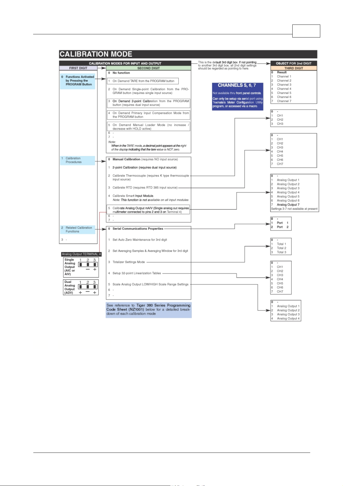
Register List
Register 4434 is a 16 bit register
in EEPROM which controls the sequence of code setups that are
displayed when the "Prog" and "Up" button are pressed. Each bit in the register controls a specific
code display as shown below. If a specific bit is a "0" then the display of the associated function is
disabled and that function will be skipped over. If a bit is a "1" the function will be displayed.
Bit 0 = not used
Bit 1 = Brightness (for LED display option only)
Bit 2 = "Lock" display
Bit 3 = Cal
Bit 4 = Display Mode Setup
Bit 5 = Analog Mode Setup
Bit 6 = Counter A Mode Setup
Bit 7 = Counter B Mode Setup
Bit 8 = Counter C Mode Setup
72
2.5.2 Config Blanking
ZEN-16-REG-MAN-18V01
© <2018> ... Define Instruments Ltd.
Page 74

Zen Registers73
Bit 9 = Counter D Mode Setup
Bit 10 = Logging Mode Setup
Bit 11 = not used
Bit 12 = not used
Bit 13 = not used
Bit 14 = not used
Bit 15 = not used
When register
4434
is read it will be displayed as a 16 bit unsigned number. The default value will be
8191 (0x1FFF hex) which is all codes enabled. If, for example, you wished to display the following
codes;
Brightness, Cal, Display Setup, Counter B Setup & Logging Setup
the resulting value for register
4434
would be;
0000 0100 1001 1010b (binary) = 0x049A (hex) = 1178 (decimal)
While programming through the front display, the programming digits of the display mode setup
provide
settings for the following display functions:
·
Indication of setpoints / relays operation thru dedicated annunciators.
·
Selecting the data source for the display, totalizers 1-6, analog output 1-7, peak / valley 1-3, CH1-
CH7 and result.
·
Selecting last digit rounding.
·
Selecting display units.
·
Selecting decimal point position.
·
Display manual loader.
·
Display with selected update rates (display shows selected register).
The
display mode setup
register is represented in
octal
format to allow 3 functions to be selected in
one digit.
Display Digit
1st Digit
2nd Digit
3rd Digit
Function
Not Used
Display Functions
Display Channel
1st Digit - Not Used
The first digit of the
display mode setup
register (bits 6 & 7) is not used at present and is reserved for
future functions. It is recommended that this be set to 0.
2nd Digit - Display Functions
The 2nd digit of the
display mode
setup register (bits 3, 4, 5) selects different display functions as per
the following options:
X0X = Normal display mode (i.e. operational display shows selected register and updates every
0.5 seconds)
X1X = Manual loader mode (display shows static value which is adjustable with Up/Down buttons)
X2X = Fast display update (display updates every 0.1 seconds)
X3X = Reserved for future development
X4X = Reserved for future development
X5X = Select data source for display, peak & valley specified in 3rd digit.
X6X = Set display format for counters specified in 3rd digit.
X7X = Set trailing text character for counters specified in 3rd digit.
2.5.3 Display Mode Setup
ZEN-16-REG-MAN-18V01
© <2018> ... Define Instruments Ltd.
Page 75

Register List
3rd Digit - Decimal Point
The 3rd digit of the
display mode
setup register (bits 0,1, 2) has different options depending on the
selection of the second digit. The various options are shown below for each relevant setting of the
second digit.
2nd digit = 0 - 4
If the 2nd digit of the
display mode
setup register is set from 0 to 4 then the 3rd digit has no function.
It is recommended that the 3rd digit be set to 0.
2nd digit = 5 (set data source)
If the 2nd digit of the
display mode
setup register is set to 5 then the 3rd digit selects which display or
peak/valley channel is being targeted. The options are shown below:
X50 = Primary display source (top line of display in dual mode or top left in multi display mode).
X51 = Second display source (lower line of display in dual mode or top right in multi display
mode).
X52 = Third display source (Lower left display - multi display mode only).
X53 = Fourth display source (Lower right display - multi display mode only).
X54 = Peak1/Valley1 data source.
X55 = Peak2/Valley2 data source.
X56 = Peak3/Valley3 data source.
X57 = not used at present.
2nd digit = 6 (set display format)
If the 2nd digit of the
display mode
setup register is set to 6 then the display format settings for the 4
counter channels can be setup, as per the selection of the 3rd digit, shown below:
X60 = not used at present.
X61 = Display format for Counter A.
X62 = Display format for Counter B.
X63 = Display format for Counter C.
X64 = Display format for Counter D.
X65 = not used at present.
X66 = not used at present.
X67 = not used at present.
2nd digit = 7 (set trailing text character)
If the 2nd digit of the
display mode
setup register is set to 7 then the trailing text character for the 4
counter channels can be setup, as per the selection of the 3rd digit, shown below:
X70 = not used at present.
X71 = Trailing text character for Counter A.
X72 = Trailing text character for Counter B.
X73 = Trailing text character for Counter C.
X74 = Trailing text character for Counter D.
X75 = not used at present.
X76 = not used at present.
X77 = not used at present.
See also
Select Data Source
Display Format
Last Digit Text Character
Registers 1 to 16383 are available as the data source for the elected display (1 up to 4), peak / valley
(1 to 3), or setpoints.
74
2.5.3.1 Select Data Source
ZEN-16-REG-MAN-18V01
© <2018> ... Define Instruments Ltd.
Page 76

Zen Registers75
Following are the most commonly used named registers:
Register Name
Register
Number
Register Name
Register
Number
Register Name
Register
Number
CH1
645
CH1_12
1
CH1_FLOAT
17
CH2
647
CH2_12
2
CH2_FLOAT
19
CH3
649
CH3_12
3
CH3_FLOAT
21
CH4
651
CH4_12
4
CH4_FLOAT
23
CH5
653
CH5_12
5
CH5_FLOAT
25
CH6
655
CH6_12
6
CH6_FLOAT
27
CH7
657
CH7_12
7
CH7_FLOAT
29
CH8
659
CH8_12
8
CH8_FLOAT
31
CH9
661
CH9_12
9
CH9_FLOAT
33
CH10
663
CH10_12
10
CH10_FLOAT
35
CH11
665
CH11_12
11
CH11_FLOAT
37
CH12
667
CH12_12
12
CH12_FLOAT
39
CH13
669
CH13_12
13
CH13_FLOAT
41
CH14
671
CH14_
1214CH14_FLOAT
43
CH15
673
CH15_12
15
CH15_FLOAT
45
CH16
675
CH16_12
16
CH16_FLOAT
47
Register Name
Register
Number
Register Name
Register
Number
Register Name
Register
Number
COUNTER_A_16
113
TOTAL10
307
AUX16
345
COUNTER_B_16
114
AUX1
315
RAW_COUNTER_A
369
COUNTER_C_16
115
AUX2
317
RAW_COUNTER_B
371
COUNTER_D_16
116
AUX3
319
RAW_COUNTER_C
373
ANALOGUE1_12
117
AUX4
321
RAW_COUNTER_D
375
ANALOGUE2_12
118
AUX5
323
PEAK1
461
DISPLAY1
223
AUX6
325
VALLEY1
463
TOTAL1
289
AUX7
327
PEAK2
465
TOTAL2
291
AUX8
329
VALLEY2
467
TOTAL3
293
AUX9
331
PEAK3
469
TOTAL4
295
AUX10
333
VALLEY3
471
TOTAL5
297
AUX11
335
SCALED_COUNTER_A
525
TOTAL6
299
AUX12
337
SCALED_COUNTER_B
527
TOTAL7
301
AUX13
339
SCALED_COUNTER_C
529
TOTAL8
303
AUX14
341
SCALED_COUNTER_D
111
TOTAL9
305
AUX15
343
ZEN-16-REG-MAN-18V01
© <2018> ... Define Instruments Ltd.
Page 77

Register List
Register Name
Register
Number
Register Name
Register
Number
Register Name
Register
Number
Register Name
Register
Number
MUX1_CH1
49
MUX2_CH1
65
MUX3_CH1
81
MUX4_CH1
97
MUX1_CH2
50
MUX2_CH2
66
MUX3_CH2
82
MUX4_CH2
98
MUX1_CH3
51
MUX2_CH3
67
MUX3_CH3
83
MUX4_CH3
99
MUX1_CH4
52
MUX2_CH4
68
MUX3_CH4
84
MUX4_CH4
100
MUX1_CH5
53
MUX2_CH5
69
MUX3_CH5
85
MUX4_CH5
101
MUX1_CH6
54
MUX2_CH6
70
MUX3_CH6
86
MUX4_CH6
102
MUX1_CH7
55
MUX2_CH7
71
MUX3_CH7
87
MUX4_CH7
103
MUX1_CH8
56
MUX2_CH8
72
MUX3_CH8
88
MUX4_CH8
104
MUX1_CH9
57
MUX2_CH9
73
MUX3_CH9
89
MUX4_CH9
105
MUX1_CH10
58
MUX2_CH10
74
MUX3_CH10
90
MUX4_CH10
106
MUX1_CH11
59
MUX2_CH11
75
MUX3_CH11
91
MUX4_CH11
107
MUX1_CH12
60
MUX2_CH12
76
MUX3_CH12
92
MUX4_CH12
108
MUX1_CH13
61
MUX2_CH13
77
MUX3_CH13
93
MUX4_CH13
109
MUX1_CH14
62
MUX2_CH14
78
MUX3_CH14
94
MUX4_CH14
110
MUX1_CH15
63
MUX2_CH15
79
MUX3_CH15
95
MUX4_CH15
111
MUX1_CH16
64
MUX2_CH16
80
MUX3_CH16
96
MUX4_CH16
112
While programming through the front display, the programming digits of the analog mode setup
register provide the settings to select supply rejection, and analogue output modes.
The analog mode setup register is represented in
octal
format to allow 3 functions to be selected in
one digit.
Display Digit
1st Digit
2nd Digit
3rd Digit
Function
Supply Rejection
Analogue O/P
Mode
Analogue O/P
Options
1st Digit - Supply Rejection
The first digit of the analog mode setup register (bits 6 & 7) are used to select the supply frequency
rejection, as shown below:
0XX = 60hz supply rejection.
1XX = 50hz supply rejection.
2XX = Reserved for future development
3XX = Reserved for future development
2nd Digit - Analogue Output Mode
The 2nd digit of the analog mode setup register (bits 3, 4, 5) selects different analogue output modes
as per the following options:
X0X = Intech 2100M driver mode.
X1X = Normal mode (SCADA).
X2X = PLC RTX (clk/rst).
X3X = PLC RTX (BCD).
X4X = Reserved for future development.
X5X = Reserved for future development.
X6X = Reserved for future development.
X7X = Reserved for future development.
76
2.5.4 Analogue Mode Setup
ZEN-16-REG-MAN-18V01
© <2018> ... Define Instruments Ltd.
Page 78

Zen Registers77
3rd Digit - Analogue Output Options
The 3rd digit of the analog mode setup register (bits 0,1, 2) has different options depending on the
selection of the second digit. The various options are shown below for each relevant setting of the
second digit.
2nd digit = 0
If the 2nd digit of the analog mode setup register is set to 0 (2100M driver mode) then the 3rd digit
functions as shown below;
X00 = 700mS delay between clock pulses.
X01 = 1 second delay between clock pulses.
X02 = 2 seconds delay between clock pulses.
X03 = 3 seconds delay between clock pulses.
X04 = 4 seconds delay between clock pulses.
X05 = 5 seconds delay between clock pulses.
X06 = 6 seconds delay between clock pulses.
X07 = 7 seconds delay between clock pulses.
2nd digit = 2
If the 2nd digit of the analog mode setup register is set to 2 (PLC RTX (clk/rst) mode) then the 3rd
digit functions as a debounce timer for the clock input pin (D2) with the following options;
X20 = No debounce time.
X21 = 2.5mS debounce time.
X22 = 5mS debounce time.
X23 = 10mS debounce time.
X24 = 25mS debounce time.
X25 = 50mS debounce time.
X26 = 100mS debounce time.
X27 = 200mS debounce time.
2nd digit = 3
If the 2nd digit of the analog mode setup register is set to 3 (PLC RTX (BCD) mode) then the 3rd digit
gives the following options;
X30 = 12 bit result values output on analogue O/P 1, 12 bit scaled setpoints output on analogue
O/P 2. (Intech compatibility mode).
X31 = 32 bit result values output on analogue O/P 1, 32 bit totals 1-10 output on analogue O/P 2.
X32 = Reserved for future development.
X33 = Reserved for future development.
X34 = Reserved for future development.
X35 = Reserved for future development.
X36 = Reserved for future development.
X37 = Reserved for future development.
Note: If the analogue mode is set to X31, BCD input values of 0-9 will cause TOTAL1 - TOTAL10
values to be output on analogue output 2. For BCD input values 10 - 15, analogue output channel 2
will operate in normal mode and output whatever register the
DATA_SOURCE_ANALOG2
points to.
2nd digit = 1 or 4-7
If the 2nd digit of the analog mode setup register is set to 1, or 3 to 7 then the 3rd digit has no
function. It is recommended that the 3rd digit be set to 0.
NOTE: Some analogue output mode settings shown above also require the use of various
digital input pins. Setting the analogue output to these modes will over ride other settings for
digital inputs (see
Counter Setup
)
See also
Counter A Setup
ZEN-16-REG-MAN-18V01
© <2018> ... Define Instruments Ltd.
Page 79

Counter B Setup
Counter C Setup
Counter D Setup
2.5.5 Counter A Mode Setup
While programming through the front display, the programming digits of the counter A mode register
allow you to select from various digital input modes associated with the DI A input pin.
The counter 1
mode
register is represented in
octal
format to allow 3 functions to be selected in one
digit.
Display Digit
1st Digit
2nd Digit
3rd Digit
Function
Reset/Restore
Digital I/P Mode
Digital I/P
Options
1st Digit - Reset/Restore Count A at Power-up
The first digit of the counter A
mode
register (bits 6 & 7) are used to select the whether the count
value for the counter A register is reset to zero at a power up or restored to the last count value
before power down. The options are as shown below:
0XX = Restore count A value at power up.
1XX = Reset count A value to zero at power up.
2XX = Apply 32 point linearization to count A and restore count A value at power up.
3XX = Apply 32 point linearization to count A and reset count A value to zero at power up.
Note:
Linearization table 1 is used for counter A linearization options 2XX and 3XX. (See
Linearization
for information).
NOTE:
Linearization is applied
AFTER
scaling and offset.
2nd Digit - DI A Digital Input Mode
The 2nd digit of the counter A
mode
register (bits 3, 4, 5) selects different digital input modes for the
DI A pin as per the following options:
X0X = Digital input only.
X1X = Counter input.
X2X = Frequency counter input.
X3X = Reserved for future development.
X4X = Reserved for future development.
X5X = Reserved for future development.
X6X = Reserved for future development.
X7X = Reserved for future development.
3rd Digit - Digital Input Options
The 3rd digit of the counter A
mode
register (bits 0,1, 2) has different options depending on the
selection of the second digit. The various options are shown below for each relevant setting of the
second digit.
2nd digit = 0 (digital input)
If the 2nd digit of the counter A
mode
register is set to 0 (digital input only) then the 3rd digit functions
as shown below;
Register List
78
ZEN-16-REG-MAN-18V01
© <2018> ... Define Instruments Ltd.
Page 80

Zen Registers79
X00 = Digital input only - no other associated functions.
X01 = Digital input which also triggers capture macro on leading edge of pulse.
X02 = Digital input with data log on leading edge of pulse.
X03 = Digital input with gated interval logging and data log on leading edge of pulse. (See
Gated Interval Logging
).
X04 = Reserved for future development.
X05 = Same as X01 above with 5mS de-bounce applied to leading edge of pulse.
X06 = Same as X02 above with 5mS de-bounce applied to leading edge of pulse.
X07 = Same as X03 above with 5mS de-bounce applied to leading edge of pulse.
(
Note:
options X03 to X07 above are only available on firmware V0.09.04+)
2nd digit = 1 (Counter input)
If the 2nd digit of the counter A
mode
register is set to 1 (counter input) then the 3rd digit functions as
shown below;
X10 = Up counter.
X11 = Up/Down counter (DI B = direction where up=DI B off, down=DI B on).
X12 = Gated up counter (DI B = gate control where count enabled if DI B=on, disabled if DI
B=off).
X13 = Reserved for future development.
X14 = De-bounced up counter.
X15 = De-bounced up/down counter (DI B = direction where up=DI B off, down = DI B on).
X16 = De-bounced gated up counter (DI B = gate control, count enabled if DI B=on, disabled if DI
B=off).
X17 = Reserved for future development.
Note
: In de-bounced count modes a 5mS de-bounce period is applied after the leading edge of a
count pulse. The de-bounce logic is only applied to the count input (i.e. no de-bounce applied to DIB
in up/down or gated count modes).
2nd digit = 2 (frequency counter input)
If the 2nd digit of the counter A
mode
register is set to 0 (digital input only) then the 3rd digit functions
as shown below;
3rd digit
X20 = Frequency counter (0.01hz - 2500.00hz) - result declines to zero without pulses (100
seconds max.).
X21 = Frequency counter (1.00hz - 2500.00hz) - result reset to zero after 1 seconds of no pulse.
X22 = Reserved for future development.
X23 = Reserved for future development.
X24 = Reserved for future development.
X25 = Reserved for future development.
X26 = Reserved for future development.
X27 = Reserved for future development.
2nd digit = 3 to 7
If the 2nd digit of the counter A
mode
register is set from 3 to 7 then the 3rd digit has no function. It is
recommended that the 3rd digit be set to 0.
NOTE: Some settings of the analog mode setup register require the use of digital input pins
for analogue output modes. These mode will over ride the settings of the digital inputs shown
above (see
analog mode setup
).
Also note that some of the counter options also use the DI B input pins. If these options are
selected here they will over ride the setup options for the DI B.
See also
ZEN-16-REG-MAN-18V01
© <2018> ... Define Instruments Ltd.
Page 81

Counter B Mode Setup
Counter C Mode Setup
Counter D Mode Setup
Analog Mode Setup
2.5.6 Counter B Mode Setup
While programming through the front display, the programming digits of the counter B mode register
allow you to select from various digital input modes associated with the DI B input pin.
The counter B mode register is represented in
octal
format to allow 3 functions to be selected in one
digit.
Display Digit
1st Digit
2nd Digit
3rd Digit
Function
Reset/Restore
Digital I/P Mode
Digital I/P
Options
1st Digit - Reset/Restore Count B at Power-up
The first digit of the counter B
mode
register (bits 6 & 7) are used to select the whether the count
value for the counter 1 register is reset to zero at a power up or restored to the last count value before
power down. The options are as shown below:
0XX = Restore count B value at power up.
1XX = Reset count B value to zero at power up.
2XX = Apply 32 point linearization to count B and restore count B value at power up.
3XX = Apply 32 point linearization to count B and reset count B value to zero at power up.
Note:
Linearization table 1 is used for counter B linearization options 2XX and 3XX. (See
Linearization
for information).
NOTE:
Linearization is applied
AFTER
scaling and offset.
2nd Digit - DI B Digital Input Mode
The 2nd digit of the counter B mode register (bits 3, 4, 5) selects different digital input modes for the
DI B pin as per the following options:
X0X = Digital input only.
X1X = Counter input.
X2X = Frequency counter input.
X3X = Reserved for future development.
X4X = Reserved for future development.
X5X = Reserved for future development.
X6X = Reserved for future development.
X7X = Reserved for future development.
3rd Digit - Digital Input Options
The 3rd digit of the counter B mode register (bits 0,1, 2) has different options depending on the
selection of the second digit. The various options are shown below for each relevant setting of the
second digit.
2nd digit = 0 (digital input)
If the 2nd digit of the counter B
mode
register is set to 0 (digital input only) then the 3rd digit functions
as shown below;
X00 = Digital input only - no other associated functions.
Register List
80
ZEN-16-REG-MAN-18V01
© <2018> ... Define Instruments Ltd.
Page 82

Zen Registers81
X01 = Digital input which also triggers capture macro on leading edge of pulse.
X02 = Digital input with data log on leading edge of pulse.
X03 = Digital input with gated interval logging and data log on leading edge of pulse. (See
Gated Interval Logging
).
X04 = Reserved for future development.
X05 = Same as X01 above with 5mS de-bounce applied to leading edge of pulse.
X06 = Same as X02 above with 5mS de-bounce applied to leading edge of pulse.
X07 = Same as X03 above with 5mS de-bounce applied to leading edge of pulse.
(
Note:
options X03 to X07 above are only available on firmware V0.09.04+)
2nd digit = 1 (Counter input)
If the 2nd digit of the counter B
mode
register is set to 1 (counter input) then the 3rd digit functions as
shown below;
X10 = Up counter.
X11 = Reserved for future development.
X12 = Reserved for future development.
X13 = Reserved for future development.
X14 = De-bounced up counter (5mS de-bounce applied to leading edge of count pulse).
X15 = Reserved for future development.
X16 = Reserved for future development.
X17 = Reserved for future development.
2nd digit = 2 (frequency counter input)
If the 2nd digit of the counter B
mode
register is set to 0 (digital input only) then the 3rd digit functions
as shown below;
3rd digit
X20 = Frequency counter (0.01hz - 2500.00hz) - result declines to zero without pulses (100
seconds max.).
X21 = Frequency counter (1.00hz - 2500.00hz) - result reset to zero after 1 seconds of no pulse.
X22 = Reserved for future development.
X23 = Reserved for future development.
X24 = Reserved for future development.
X25 = Reserved for future development.
X26 = Reserved for future development.
X27 = Reserved for future development.
2nd digit = 3 to 7
If the 2nd digit of the counter B
mode
register is set from 3 to 7 then the 3rd digit has no function. It is
recommended that the 3rd digit be set to 0.
NOTE: Some settings of the analog mode setup register require the use of digital input pins
for analogue output modes. These mode will over ride the settings of the digital inputs shown
above (see
analog mode setup
).
Note also that some of the counter functions for the DI A pin also require the use of the DI B
pin and in these modes the above settings for DI B will be overridden. (see
Counter A Mode Setup
).
See also
Counter A Mode Setup
Counter C Mode Setup
Counter D Mode Setup
Analog Mode Setup
ZEN-16-REG-MAN-18V01
© <2018> ... Define Instruments Ltd.
Page 83

2.5.7 Counter C Mode Setup
While programming through the front display, the programming digits of the counter C mode register
allow you to select from various digital input modes associated with the DI C input pin.
The counter C mode register is represented in
octal
format to allow 3 functions to be selected in one
digit.
Display Digit
1st Digit
2nd Digit
3rd Digit
Function
Reset/Restore
Digital I/P Mode
Digital I/P
Options
1st Digit - Reset/Restore Count C at Power-up
The first digit of the counter C mode register (bits 6 & 7) are used to select the whether the count
value for the counter C register is reset to zero at a power up or restored to the last count value
before power down. The options are as shown below:
0XX = Restore count C value at power up.
1XX = Reset count C value to zero at power up.
2XX = Apply 32 point linearization to count C and restore count C value at power up.
3XX = Apply 32 point linearization to count C and reset count C value to zero at power up.
NOTE:
Linearization is applied
AFTER
scaling and offset.
2nd Digit - DI C Digital Input Mode
The 2nd digit of the counter C mode register (bits 3, 4, 5) selects different digital input modes for the
DI C pin as per the following options:
X0X = Digital input only.
X1X = Counter input.
X2X = Frequency counter input.
X3X = Reserved for future development.
X4X = Reserved for future development.
X5X = Reserved for future development.
X6X = Reserved for future development.
X7X = Reserved for future development.
3rd Digit - Digital Input Options
The 3rd digit of the counter C mode register (bits 0,1, 2) has different options depending on the
selection of the second digit. The various options are shown below for each relevant setting of the
second digit.
2nd digit = 0 (digital input)
If the 2nd digit of the counter C
mode
register is set to 0 (digital input only) then the 3rd digit functions
as shown below;
X00 = Digital input only - no other associated functions.
X01 = Digital input which also triggers capture macro on leading edge of pulse.
X02 = Digital input with data log on leading edge of pulse.
X03 = Digital input with gated interval logging and data log on leading edge of pulse. (See
Gated Interval Logging
).
X04 = Reserved for future development.
X05 = Same as X01 above with 5mS de-bounce applied to leading edge of pulse.
X06 = Same as X02 above with 5mS de-bounce applied to leading edge of pulse.
X07 = Same as X03 above with 5mS de-bounce applied to leading edge of pulse.
(
Note:
options X03 to X07 above are only available on firmware V0.09.04+)
2nd digit = 1 (Counter input)
Register List
82
ZEN-16-REG-MAN-18V01
© <2018> ... Define Instruments Ltd.
Page 84

Zen Registers83
If the 2nd digit of the counter C
mode
register is set to 1 (counter input) then the 3rd digit functions as
shown below;
X10 = Up counter.
X11 = Up/Down counter (DI D = direction where up=DI D off, down=DI Don).
X12 = Gated up counter (DI D = gate control where count enabled if DI D=on, disabled DDI
D=off).
X13 = Reserved for future development.
X14 = De-bounced up counter.
X15 = De-bounced up/down counter (DI D = direction where up=DI D off, down=DI Don).
X16 = De-bounced gated up counter (DI D = gate control, count enabled if DI D=on, disabled DI
D=off).
X17 = Reserved for future development.
Note:
In de-bounced count modes a 5mS de-bounce period is applied to the leading edge of a count
pulse. The de-bounce logic is only applied to the count input (i.e. no de-bounce applied to DI D in
up/down or gated count modes).
2nd digit = 2 (frequency counter input)
If the 2nd digit of the counter C
mode
register is set to 0 (digital input only) then the 3rd digit functions
as shown below;
3rd digit
X20 = Frequency counter (0.01hz - 2500.00hz) - result declines to zero without pulses (100
seconds max.).
X21 = Frequency counter (1.00hz - 2500.00hz) - result reset to zero after 1 seconds of no pulse.
X22 = Reserved for future development.
X23 = Reserved for future development.
X24 = Reserved for future development.
X25 = Reserved for future development.
X26 = Reserved for future development.
X27 = Reserved for future development.
2nd digit = 3 to 7
If the 2nd digit of the counter C
mode
register is set from 3 to 7 then the 3rd digit has no function. It is
recommended that the 3rd digit be set to 0.
NOTE: Some settings of the analog mode setup register require the use of digital input pins
for analogue output modes. These mode will over ride the settings of the digital inputs shown
above (see
analog mode setup
).
Also note that some of the counter options also use the
DI D
input pins. If these options are
selected here they will over ride the setup options for the
DI D
.
See also
Counter A Mode Setup
Counter B Mode Setup
Counter D Mode Setup
Analog Mode Setup
While programming through the front display, the programming digits of the counter D mode register
allow you to select from various digital input modes associated with the DI D input pin.
The counter D mode register is represented in
octal
format to allow 3 functions to be selected in one
digit.
2.5.8 Counter D Mode Setup
ZEN-16-REG-MAN-18V01
© <2018> ... Define Instruments Ltd.
Page 85

Register List
Display Digit
1st Digit
2nd Digit
3rd Digit
Function
Reset/Restore
Digital I/P Mode
Digital I/P
Options
1st Digit - Reset/Restore Count D at Power-up
The first digit of the counter D mode register (bits 6 & 7) are used to select the whether the count
value for the counter D register is reset to zero at a power up or restored to the last count value
before power down. The options are as shown below:
0XX = Restore count D value at power up.
1XX = Reset count D value to zero at power up.
2XX = Apply 32 point linearization to count D and restore count D value at power up.
3XX = Apply 32 point linearization to count D and reset count D value to zero at power up.
NOTE:
Linearization is applied
AFTER
scaling and offset.
2nd Digit - DI D Digital Input Mode
The 2nd digit of the counter D mode register (bits 3, 4, 5) selects different digital input modes for the
DI D pin as per the following options:
X0X = Digital input only.
X1X = Counter input.
X2X = Frequency counter input.
X3X = Reserved for future development.
X4X = Reserved for future development.
X5X = Reserved for future development.
X6X = Reserved for future development.
X7X = Reserved for future development.
3rd Digit - Digital Input Options
The 3rd digit of the counter D mode register (bits 0,1, 2) has different options depending on the
selection of the second digit. The various options are shown below for each relevant setting of the
second digit.
2nd digit = 0 (digital input)
If the 2nd digit of the counter D
mode
register is set to 0 (digital input only) then the 3rd digit functions
as shown below;
X00 = Digital input only - no other associated functions.
X01 = Digital input which also triggers capture macro on leading edge of pulse.
X02 = Digital input with data log on leading edge of pulse.
X03 = Digital input with gated interval logging and data log on leading edge of pulse. (See
Gated Interval Logging
).
X04 = Reserved for future development.
X05 = Same as X01 above with 5mS de-bounce applied to leading edge of pulse.
X06 = Same as X02 above with 5mS de-bounce applied to leading edge of pulse.
X07 = Same as X03 above with 5mS de-bounce applied to leading edge of pulse.
(
Note:
options X03 to X07 above are only available on firmware V0.09.04+)
2nd digit = 1 (Counter input)
If the 2nd digit of the counter D
mode
register is set to 1 (counter input) then the 3rd digit functions as
shown below;
X10 = Up counter.
X11 = Reserved for future development.
X12 = Reserved for future development.
X13 = Reserved for future development.
84
ZEN-16-REG-MAN-18V01
© <2018> ... Define Instruments Ltd.
Page 86

Zen Registers85
X14 = De-bounced up counter (5ms de-bounce applied to leading edge of count pulse).
X15 = Reserved for future development.
X16 = Reserved for future development.
X17 = Reserved for future development.
2nd digit = 2 (frequency counter input)
If the 2nd digit of the counter D
mode
register is set to 0 (digital input only) then the 3rd digit functions
as shown below;
3rd digit
X20 = Frequency counter (0.01hz - 2500.00hz) - result declines to zero without pulses (100
seconds max.).
X21 = Frequency counter (1.00hz - 2500.00hz) - result reset to zero after 1 seconds of no pulse.
X22 = Reserved for future development.
X23 = Reserved for future development.
X24 = Reserved for future development.
X25 = Reserved for future development.
X26 = Reserved for future development.
X27 = Reserved for future development.
2nd digit = 3 to 7
If the 2nd digit of the counter D
mode
register is set from 3 to 7 then the 3rd digit has no function. It is
recommended that the 3rd digit be set to 0.
NOTE: Some settings of the analog mode setup register require the use of digital input pins
for analogue output modes. These mode will over ride the settings of the digital inputs shown
above (see
analog mode setup
).
Note also that some of the counter functions for the DI C pin also require the use of the DI D
pin and in these modes the above settings for DI D will be overridden. (see
Counter C Mode Setup
).
See also
Counter A Mode Setup
Counter B Mode Setup
Counter C Mode Setup
Analog Mode Setup
While programming through the front display, the programming digits of logging mode setup allow
you to select data logging and print mode options.
The
logging mode
setup register is represented in
octal
format to allow 3 functions to be selected in
one digit.
Display Digit
1st Digit
2nd Digit
3rd Digit
Function
Logging/buffer Control
Date/Time/Print
Options
Manual Trigger
Options
1st Digit - Logging Buffer Control
The first digit of the
logging mode
setup register (bits 6 & 7) are used to enable data logging and
select the type of data logging buffer, as shown below:
0XX = Data logging disabled.
1XX = Data logging enabled - cyclic buffer (wraps around to 1 when it reaches the end of data
2.5.9 Logging Mode Setup
ZEN-16-REG-MAN-18V01
© <2018> ... Define Instruments Ltd.
Page 87

Register List
logging memory).
2XX = Data logging enabled - linear buffer (logging stops when it reaches the end of data logging
memory).
3XX = Reserved for future development.
2nd Digit - Date/Time/Print Options
The 2nd digit of the
logging mode
setup register (bits 3, 4, 5) selects different time stamp and print
output options as shown below:
X0X = Printer output - no time stamp.
X1X = Printer output - with time stamp (Month/Day/Year Hrs:Min:Sec).
X2X = Printer output - with time stamp (Day/Month/Year Hrs:Min:Sec).
X3X = Printer output - with time stamp (Hrs:Min:Sec).
X4X = Spreadsheet output - no time stamp.
X5X = Spreadsheet output - with time stamp (Month/Day/Year Hrs:Min:Sec).
X6X = Spreadsheet output - with time stamp (Day/Month/Year Hrs:Min:Sec).
X7X = Spreadsheet output - with time stamp (Hrs:Min:Sec).
3rd Digit - Manual Trigger Options
The 3rd digit of the
logging mode
setup register (bits 0,1, 2) selects different options to manually
trigger a log sample from push button switches. The various options are shown below;
XX0 = No manual trigger.
XX1 = Trigger log sample from Prog button.
XX2 = Trigger log sample from F1 button.
XX3 = Trigger log sample from F2 button.
XX4 = Reserved for future development.
XX5 = Reserved for future development.
XX6 = Reserved for future development.
XX7 = Reserved for future development.
See also
Data Logging
Data Logging Concepts
The
Zen16
controller includes 4 digital input pins. These can be configured for a variety of different
input functions including standard digital status inputs, various counter modes and frequency counter
modes.
The 4 digital input pins are isolated from the other
Zen16
pins by opto couplers but all share the same
common pin. The maximum frequency of these input pins is limited to approximately 2.5kHz. or pulse
widths > 200uS.
Each of the 4 digital channels has a number of associated registers which hold result and setup data.
The result registers are normally updated by the operating system of the controller after each new
input sample is processed.
The result registers can be read or written to, however the outcome of a
write operation to a result register will vary depending on the operational mode of the counter. The
following outcomes are possible.
Digital Input Mode
If the counter channel is placed in the digital input only mode (see
Counter Mode Setup
and
Analog Mode Setup
) the COUNTER_x register will show a value of "1" or "0" to reflect the current
input status of the digital input pin (
Note: this only applies to firmware versions 0.09.03 onwards
). The
result registers COUNTER_x_SCALED, COUNTER_x_RAW and COUNTER_x_16 are totally
separate from each other and they are not updated by the operating system. They can be used as
86
2.6 Counters
ZEN-16-REG-MAN-18V01
© <2018> ... Define Instruments Ltd.
Page 88

Zen Registers87
storage registers by the serial port or the macro.
Gated Interval Logging
Firmware V0.09.04 onwards includes a gated interval logging option. When this option is selected for
one of the digital status input pins, normal data logging will be disabled when the digital input is in-
active. Data will only be logged at the rate specified by the LOG_INTERVAL_TIME when the digital
input is active (i.e. "ON"). If 2 or more of the digital status inputs are setup in this mode then they
form an "AND" function and normal data logging will be activated when all selected inputs are active.
The leading edge of a pulse will also be logged with the trigger type for the digital input.
Counter Input Mode
If the counter channel is placed in the counter mode (i.e. up counter or up/down counter) then input
counts are applied to the COUNTERx_RAW register, which is then scaled and applied to the
COUNTER_x_SCALED register. If 32 point linearization is enabled then the COUNTER_x_SCALED
value is taken as an input value and the linearized output value is applied to COUNTER_x. If 32 point
linearization is disabled, the COUNTER_x_SCALED value will be copied into the COUNTER_x
register directly. So these registers are updated by the operating system after each new input sample.
However, a write to these registers is still possible in counter mode to enable the setting or resetting
of the count value.
The COUNTER_x_16 register is effectively a copy of the COUNTER_x_RAW register, and is
provided to maintain compatibility which older products.
Note
: Because COUNTER_x_16 is only a 16 bit register, it will only show the lowest 16 bits of the
COUNTER_x_RAW register. For example, if COUNTER_x_RAW equals 65536 counts then
COUNTER_x_16 will show a value of 0.
A write to the COUNTER_x_RAW register will effect the COUNTER_x_SCALED, COUNTER_x and
COUNTER_x_16 registers. The COUNTER_x register will be updated in accordance with the scale
and offset values applied to the counter channel, and any linearization settings. The COUNTER_x_16
register will basically be a copy of the lowest 16 bits of COUNTER_x_RAW.
A write to the COUNTER_x_SCALED register will update the COUNTER_x_RAW register in
accordance with the scale and offset values applied to the counter channel. This inturn will cause the
COUNTER_x_16 and COUNTER_x registers to be updated with a new value as well. Note:if the
value written to COUNTER_x_SCALED causes the COUNTER_x_RAW value to be greater than
65535, then COUNTER_x_16 will only show the lowest 16 bits of COUNTER_x_RAW.
A write to the COUNTERx_16 register will also update the COUNTERx_RAW register with the same
value. COUNTERx_SCALED and COUNTERx registers will also be updated on the next sample
accordance with the scale and offset values and any linearization applied to the counter channel. .
Frequency Counter Input Mode
If the counter channel is placed in the frequency counter mode then the frequency in Hz is applied to
the COUNTER_x_RAW register, which is then scaled and applied to the COUNTER_x_SCALED
register. If 32 point linearization is enabled then the COUNTER_x_SCALED value is taken as an
input value and the linearized output value is applied to COUNTER_x. If 32 point linearization is
disabled, the COUNTER_x_SCALED value will be copied into the COUNTER_x register directly. So
these registers are updated by the operating system after each new input sample. Any writes to these
register will be lost because the operating system is continuously over writing them with new input
samples.
Note
: In frequency counter mode COUNTER_x_16 registers are hold a 16 bit copy of
COUNTER_x_RAW register. If COUNTER_x_RAW > 65535 then COUNTER_x_16 will display
65535. This is different to straight counter mode - see
Counter Input Mode
.
See also
Counter A
ZEN-16-REG-MAN-18V01
© <2018> ... Define Instruments Ltd.
Page 89

Counter B
Counter C
Counter D
2.6.1 Counter A
Counter A can be operated in various count and frequency counter modes.
Name
Description
Symbol
Type
Register
Number
Memory
Type
COUNTER_A
32-bit register that holds the processed data for counter
A. If 32 point linearization is applied to counter A then
this register will hold the linearized output value. If
linearization is disabled, this register will be a copy of
the COUNTER_A_SCALED register. (Data may be
count or frequency data). Scaling and decimal point
values are based on those specified in the
Counter A Setup Registers
)
S_32
525
RAM
COUNTER_A_SCALE
D
32-bit register that holds the scaled data for counter A.
(Data may be count or frequency data). Scaling and
decimal point values are based on those specified in
the
Counter A Setup Registers
)
S_32
709
RAM
COUNTER_A_RAW
32-bit register that holds the raw counter value for
counter A before scaling is applied. This value is saved
in NV memory at power down and can be restored at
power up. (see
Counter A Mode Setup
for more info)
S_32
369
RAM/FLASH
COUNTER_A_16
16-bit register that holds the processed data for
COUNTER_A_16. (Range from 0 - 65535) This
register is used to maintain backwards compatibility
with older Intech products.
U_16
113
RAM
COUNTER_A_FLOAT
32-bit register that holds a pseudo floating point image
of processed data for counter A. Scaling and decimal
point values are based on those specified in the
Counter A Setup Registers
). (See
32-
bit Pseudo Floating Point
).
PF_32
1805
RAM
DI A
1-bit read only flag that indicates the status of the DI A
digital input pin. (See
Internal Digital Inputs
)
B_0_R
4108
RAM
NOTE
: Most of the above registers are normally updated by the operating system of the controller
after a new input sample is processed. If the channel is disabled or in a counter mode, it is also
possible to modify the contents of the register by writing to it from the setpoint reset logic, from the
Macro, or via the serial port. A write to these registers in other operational modes may result in the
newly written value being overwritten by the operating system in the controller. (See
Digital Input Mode
,
Counter Input Mode
and
Frequency Counter Input Mode
)
See also
Counters
Counter A Setup Registers
Counter A Mode Setup
Register List
88
ZEN-16-REG-MAN-18V01
© <2018> ... Define Instruments Ltd.
Page 90

Zen Registers89
Name
Description
Symbol
Type
Register
Number
Memory Type
OFFSET_COUNTER_A
32-bit register. Holds the calibration offset for
COUNTER_A.
S_32
359
RAM/EEPROM
SCALE_FACTOR_COUNTER_A
32-bit floating point register. Holds the
calibration scale factor for COUNTER_A.
F_32
1129
RAM/EEPROM
AVERAGING_SAMPLES_COUNTER_A
8-bit register sets the averaging samples for
COUNTER_A and COUNTER_A_16. Note:
averaging is only applied in frequency counter
mode, not in counter mode. (Range 0 to 255,
0=off)..
U_8
8311
RAM/EEPROM
AVERAGING _WINDOW_COUNTER_A
16-bit register sets the averaging window size for
COUNTER_A and COUNTER_A_16. Note:
averaging is only applied in frequency counter
mode, not in counter mode. (Range 0 to 65535,
0=window mode turned off)..
u_16
4419
RAM/EEPROM
COUNTER_A_MODE
8-bit register sets the input mode for D1,
COUNTER_A and COUNTER_A_16. (see
Counter A Mode Setup
)
U_8
8196
RAM/EEPROM
COUNTER_A_TEXT
Text display for COUNTER_A.
L_30
16427
EEROM
UNITS_TEXT_COUNTER_A
Units text for
COUNTER
_A. (Note: this is a
storage register used by external applications. It
is not shown on the standard display.)
L_14
17441
EEROM
DISPLAY_FORMAT_COUNTER_A
8-bit register. Controls the display format
settings for COUNTER_A (displayed in
octal
format).
O_8
8317
RAM/EEPROM
TEXT_CHARACTER_COUNTER_A
8-bit register. Holds the ASCII value for the last
digit text character for COUNTER_A (0 = no
character).
U_8
8371
RAM/EEPROM
See also
Counter A
Counter A Mode Setup
Counters
Counter B can be operated in various count and frequency counter modes.
2.6.1.1 Counter A Setup Registers
2.6.2 Counter B
ZEN-16-REG-MAN-18V01
© <2018> ... Define Instruments Ltd.
Page 91

Register List
Name
Description
Symbol
Type
Register
Number
Memory
Type
COUNTER_B
32-bit register that holds the processed data for counter
B. If 32 point linearization is applied to counter B then
this register will hold the linearized output value. If
linearization is disabled, this register will be a copy of
the COUNTER_B_SCALED register. (Data may be
count or frequency data). Scaling and decimal point
values are based on those specified in the
Counter B Setup Registers
)
S_32
527
RAM
COUNTER_B_SCALE
D
32-bit register that holds the scaled data for counter B.
(Data may be count or frequency data). Scaling and
decimal point values are based on those specified in
the
Counter B Setup Registers
)
S_32
711
RAM
COUNTER_B_RAW
32-bit register that holds the raw counter value for
counter B before scaling is applied. This value is saved
in NV memory at power down and can be restored at
power up. (see
Counter B Mode Setup
for more info)
S_32
371
RAM/FLASH
COUNTER_B_16
16-bit register that holds the processed data for
COUNTER_B_16. (Range from 0 - 65535) This
register is used to maintain backwards compatibility
with older Intech products.
U_16
114
RAM
COUNTER_B_FLOAT
32-bit register that holds a pseudo floating point image
of processed data for counter B. Scaling and decimal
point values are based on those specified in the
Counter B Setup Registers
). (See
32-
bit Pseudo Floating Point
).
PF_32
1807
RAM
DI B
1-bit read only flag that indicates the status of the DI B
digital input pin. (See
Internal Digital Inputs
)
B_1_R
4108
RAM
NOTE
: Most of the above registers are normally updated by the operating system of the controller
after a new input sample is processed. If the channel is disabled or in a counter mode, it is also
possible to modify the contents of the register by writing to it from the setpoint reset logic, from the
Macro, or via the serial port. A write to these registers in other operational modes may result in the
newly written value being overwritten by the operating system in the controller. (See
Digital Input Mode
,
Counter Input Mode
and
Frequency Counter Input Mode
)
See also
Counters
Counter B Setup Registers
Counter B Mode Setup
Name
Description
Symbol
Type
Register
Number
Memory Type
OFFSET_COUNTER_B
32-bit register. Holds the calibration offset for
COUNTER_B.
S_32
361
RAM/EEPROM
SCALE_FACTOR_COUNTER_B
32-bit floating point register. Holds the
calibration scale factor for COUNTER_B.
F_32
1131
RAM/EEPROM
AVERAGING_SAMPLES_COUNTER_B
8-bit register sets the averaging samples for
COUNTER_Band COUNTER_B_16. Note:
averaging is only applied in frequency counter
mode, not in counter mode. (Range 0 to 255,
0=off)..
U_8
8312
RAM/EEPROM
90
2.6.2.1 Counter B Setup Registers
ZEN-16-REG-MAN-18V01
© <2018> ... Define Instruments Ltd.
Page 92

Zen Registers91
AVERAGING _WINDOW_COUNTER_B
16-bit register sets the averaging window size for
COUNTER_B and COUNTER_B_16. Note:
averaging is only applied in frequency counter
mode, not in counter mode. (Range 0 to 65535,
0=window mode turned off)..
u_16
4420
RAM/EEPROM
COUNTER_B_MODE
8-bit register sets the input mode for D1,
COUNTER_B and COUNTER_B_16. (see
Counter B Mode Setup
)
U_8
8197
RAM/EEPROM
COUNTER_B_TEXT
Text display for COUNTER_B.
L_30
16429
EEROM
UNITS_TEXT_COUNTER_B
Units text for
COUNTER
_B. (Note: this is a
storage register used by external applications. It
is not shown on the standard display.)
L_14
17443
EEROM
DISPLAY_FORMAT_COUNTER_B
8-bit register. Controls the display format
settings for COUNTER_B (displayed in
octal
format).
O_8
8318
RAM/EEPROM
TEXT_CHARACTER_COUNTER_B
8-bit register. Holds the ASCII value for the last
digit text character for COUNTER_B (0 = no
character).
U_8
8372
RAM/EEPROM
See also
Counter B
Counter B Mode Setup
Counters
Counter C can be operated in various count and frequency counter modes.
Name
Description
Symbol
Type
Register
Number
Memory
Type
COUNTER_C
32-bit register that holds the processed data for counter
VC. If 32 point linearization is applied to counter C then
this register will hold the linearized output value. If
linearization is disabled, this register will be a copy of
the COUNTER_C_SCALED register. (Data may be
count or frequency data). Scaling and decimal point
values are based on those specified in the
Counter C Setup Registers
)
S_32
529
RAM
COUNTER_C_SCALED
32-bit register that holds the scaled data for counter C.
(Data may be count or frequency data). Scaling and
decimal point values are based on those specified in
the
Counter C Setup Registers
)
S_32
713
RAM
COUNTER_C_RAW
32-bit register that holds the raw counter value for
counter C before scaling is applied. This value is saved
in NV memory at power down and can be restored at
power up. (see
Counter C Mode Setup
for more info)
S_32
373
RAM/FLASH
COUNTER_C_16
16-bit register that holds the processed data for
COUNTER_C_16. (Range from 0 - 65535) This
register is used to maintain backwards compatibility
with older Intech products.
U_16
115
RAM
COUNTER_C_FLOAT
32-bit register that holds a pseudo floating point image
of the processed data for counter C. Scaling and
decimal point values are based on those specified in
the
Counter C Setup Registers
). (See
32-
bit Pseudo Floating Point
).
PF_32
1809
RAM
DI C
1-bit read only flag that indicates the status of the DI C
digital input pin. (See
Internal Digital Inputs
)
B_2_R
4108
RAM
NOTE
: Most of the above registers are normally updated by the operating system of the controller
2.6.3 Counter C
ZEN-16-REG-MAN-18V01
© <2018> ... Define Instruments Ltd.
Page 93

after a new input sample is processed. If the channel is disabled or in a counter mode, it is also
possible to modify the contents of the register by writing to it from the setpoint reset logic, from the
Macro, or via the serial port. A write to these registers in other operational modes may result in the
newly written value being overwritten by the operating system in the controller. (See
Digital Input Mode
,
Counter Input Mode
and
Frequency Counter Input Mode
)
See also
Counters
Counter C Setup Registers
Counter C Mode Setup
2.6.3.1 Counter C Setup Registers
Name
Description
Symbol
Type
Register
Number
Memory Type
OFFSET_COUNTER_C
32-bit register. Holds the calibration offset for
COUNTER_C.
S_32
363
RAM/EEPROM
SCALE_FACTOR_COUNTER_C
32-bit floating point register. Holds the
calibration scale factor for COUNTER_C.
F_32
1133
RAM/EEPROM
AVERAGING_SAMPLES_COUNTER_C
8-bit register sets the averaging samples for
COUNTER_C and COUNTER_C_16. Note:
averaging is only applied in frequency counter
mode, not in counter mode. (Range 0 to 255,
0=off)..
U_8
8313
RAM/EEPROM
AVERAGING _WINDOW_COUNTER_C
16-bit register sets the averaging window size for
COUNTER_C and COUNTER_C_16. Note:
averaging is only applied in frequency counter
mode, not in counter mode. (Range 0 to 65535,
0=window mode turned off)..
u_16
4421
RAM/EEPROM
COUNTER_C_MODE
8-bit register sets the input mode for D1,
COUNTER_C and COUNTER_C_16. (see
Counter C Mode Setup
)
U_8
8198
RAM/EEPROM
COUNTER_C_TEXT
Text display for COUNTER_C.
L_30
16431
EEROM
UNITS_TEXT_COUNTER_C
Units text for
COUNTER_C
. (Note: this is a
storage register used by external applications. It
is not shown on the standard display.)
L_14
17445
EEROM
DISPLAY_FORMAT_COUNTER_C
8-bit register. Controls the display format
settings for COUNTER_C (displayed in
octal
format).
O_8
8319
RAM/EEPROM
TEXT_CHARACTER_COUNTER_C
8-bit register. Holds the ASCII value for the last
digit text character for COUNTER_C (0 = no
character).
U_8
8373
RAM/EEPROM
See also
Counter C
Counter C Mode Setup
Counters
Register List
92
ZEN-16-REG-MAN-18V01
© <2018> ... Define Instruments Ltd.
Page 94

Zen Registers93
Counter D can be operated in various count and frequency counter modes.
Name
Description
Symbol
Type
Register
Number
Memory
Type
COUNTER_D
32-bit register that holds the processed data for counter
D. If 32 point linearisation is applied to counter D then
this register will hold the linearisaed output value. If
linearisation is disabled, this register will be a copy of
the COUNTER_D_SCALED register. (Data may be
count or frequency data). Scaling and decimal point
values are based on those specified in the
Counter D Setup Registers
)
S_32
531
RAM
COUNTER_D_SCALED
32-bit register that holds the scaled data for counter D.
(Data may be count or frequency data). Scaling and
decimal point values are based on those specified in
the
Counter D Setup Registers
)
S_32
715
RAM
COUNTER_D_RAW
32-bit register that holds the raw counter value for
counter D before scaling is applied. This value is saved
in NV memory at power down and can be restored at
power up. (see
Counter D Mode Setup
for more info)
S_32
375
RAM/FLASH
COUNTER_D_16
16-bit register that holds the processed data for
COUNTER_D_16. (Range from 0 - 65535) This
register is used to maintain backwards compatibility
with older Intech products.
U_16
116
RAM
COUNTER_D_FLOAT
32-bit register that holds a pseudo floating point image
of the processed data for counter D. Scaling and
decimal point values are based on those specified in
the
Counter D Setup Registers
). (See
32-
bit Pseudo Floating Point
).
PF_32
1811
RAM
DI D
1-bit read only flag that indicates the status of the DI D
digital input pin. (See
Internal Digital Inputs
)
B_3_R
4108
RAM
NOTE
: Most of the above registers are normally updated by the operating system of the controller
after a new input sample is processed. If the channel is disabled or in a counter mode, it is also
possible to modify the contents of the register by writing to it from the setpoint reset logic, from the
Macro, or via the serial port. A write to these registers in other operational modes may result in the
newly written value being overwritten by the operating system in the controller. (See
Digital Input Mode
,
Counter Input Mode
and
Frequency Counter Input Mode
)
See also
Counters
Counter D Setup Registers
Counter D Mode Setup
2.6.4 Counter D
ZEN-16-REG-MAN-18V01
© <2018> ... Define Instruments Ltd.
Page 95

2.6.4.1 Counter D Setup Registers
Name
Description
Symbol
Type
Register
Number
Memory Type
OFFSET_COUNTER_D
32-bit register. Holds the calibration offset for
COUNTER_D.
S_32
365
RAM/EEPROM
SCALE_FACTOR_COUNTER_D
32-bit floating point register. Holds the
calibration scale factor for COUNTER_D.
F_32
1135
RAM/EEPROM
AVERAGING_SAMPLES_COUNTER_D
8-bit register sets the averaging samples for
COUNTER_D and COUNTER_D_16. Note:
averaging is only applied in frequency counter
mode, not in counter mode. (Range 0 to 255,
0=off)..
U_8
8314
RAM/EEPROM
AVERAGING _WINDOW_COUNTER_D
16-bit register sets the averaging window size for
COUNTER_D and COUNTER_D_16. Note:
averaging is only applied in frequency counter
mode, not in counter mode. (Range 0 to 65535,
0=window mode turned off)..
u_16
4422
RAM/EEPROM
COUNTER_D_MODE
8-bit register sets the input mode for D1,
COUNTER_D and COUNTER_D_16. (see
Counter D Mode Setup
)
U_8
8199
RAM/EEPROM
COUNTER_D_TEXT
Text display for COUNTER_D.
L_30
16433
EEROM
UNITS_TEXT_COUNTER_D
Units text for
COUNTER
_D. (Note: this is a
storage register used by external applications. It
is not shown on the standard display.)
L_14
17447
EEROM
DISPLAY_FORMAT_COUNTER_D
8-bit register. Controls the display format
settings for COUNTER_D (displayed in
octal
format).
O_8
8320
RAM/EEPROM
TEXT_CHARACTER_COUNTER_D
8-bit register. Holds the ASCII value for the last
digit text character for COUNTER_D (0 = no
character).
U_8
8374
RAM/EEPROM
See also
Counter D
Counter D Mode Setup
Counters
Most registers from register #1 to register #32765 can be logged. Registers are logged according to
what type of register they are, with floating point and text registers also able to be logged. The Zen16
controllers can log up to 32 different channels in each sample (depending on the data type/size of
each channel being logged).
31,774 samples (data records) can be stored (logged) in internal non-volatile memory for before and
after analysis of any process condition. (Note: If a uSD card data logging option is used then the
number of samples are related to the uSD card size.)
Note: Some models of Zen16 controllers do come with RTC and data FLASH memory installed. The
Zen16 controller
must have either
RTC/data FLASH memory installed or the additional uSD data
logging option installed for data logging to function.
Data logging can be triggered (activated) from the logging timer, a setpoint, a front panel button, an
external switch, via the serial port or from a macro command. With a real-time clock installed, date
and time stamps can be included.
See also
Register List
94
2.7 Data Logging
ZEN-16-REG-MAN-18V01
© <2018> ... Define Instruments Ltd.
Page 96

Zen Registers95
Data Logging Concepts
Name
Description
Symbol
Type
Register
Number
Memory Type
LOG_READ_COUNT
16-bit register. Sets the number of log samples
to read using register 16555 (range 0 to 65535).
U_16
4439
RAM/EEPROM
LOG_WRITE_POINTER
32-bit register. Points to the most recent data log
sample number written by the controller. (Pointer
is pre-incremented before each new sample is
written).
U_32
489
RAM/FLASH/SDcar
d
LOG_READ_POINTER
32-bit register. Pointer to the most recent data
log sample number read by the controller. Pre-
incremented before each read of 16553.
U_32
491
RAM/FLASH/SDcar
d
LOG_REVERSE_READ_POINTER
32-bit register. Pointer to the next data log
sample number to be read by the controller when
using the
U_32
485
RAM/FLASH
DELIMIT_CHAR
8-bit register. Holds delimiting character for
spread sheet output mode. Value is held in
volatile RAM which defaults to Horizontal Tab
(0x9) at power on.
U_8
8452
RAM
LOG_INTERVAL_TIME
32-bit register. Logging interval time. Specifies
the amount of time at which log samples are
taken in 0.1 second resolution.
U_32
483
RAM/EEPROM
LOGGING_MODE
8-bit register. Enables data logging and controls
buffer type, time stamp and manual trigger
modes. (see
Logging Mode Setup
)
O_8
8200
RAM/EEPROM
LOG_REG1
16-bit register. Contains register number of 1st
register logged in sample.
U_16
4275
RAM/EEPROM
LOG_REG2
16-bit register. Contains register number of 2nd
register logged in sample.
U_16
4276
RAM/EEPROM
LOG_REG3
16-bit register. Contains register number of 3rd
register logged in sample.
U_16
4277
RAM/EEPROM
LOG_REG4
16-bit register. Contains register number of 4th
register logged in sample.
U_16
4278
RAM/EEPROM
LOG_REG5
16-bit register. Contains register number of 5th
register logged in sample.
U_16
4279
RAM/EEPROM
LOG_REG6
16-bit register. Contains register number of 6th
register logged in sample.
U_16
4280
RAM/EEPROM
LOG_REG7
16-bit register. Contains register number of 7th
register logged in sample.
U_16 4281
RAM/EEPROM
LOG_REG8
16-bit register. Contains register number of 8th
register logged in sample.
U_16
4282
RAM/EEPROM
LOG_REG9
16-bit register. Contains register number of 9th
register logged in sample.
U_16
4283
RAM/EEPROM
LOG_REG10
16-bit register. Contains register number of 10th
register logged in sample.
U_16
4284
RAM/EEPROM
LOG_REG11
16-bit register. Contains register number of 11th
register logged in sample.
U_16
4285
RAM/EEPROM
ZEN-16-REG-MAN-18V01
© <2018> ... Define Instruments Ltd.
Page 97

Register List
LOG_REG12
16-bit register. Contains register number of 12th
register logged in sample.
U_16
4286
RAM/EEPROM
LOG_REG13
16-bit register. Contains register number of 13th
register logged in sample.
U_16
4287
RAM/EEPROM
LOG_REG14
16-bit register. Contains register number of 14th
register logged in sample.
U_16
4288
RAM/EEPROM
LOG_REG15
16-bit register. Contains register number of 15th
register logged in sample.
U_16
4289
RAM/EEPROM
LOG_REG16
16-bit register. Contains register number of 16th
register logged in sample.
U_16
4290
RAM/EEPROM
LOG_REG17
16-bit register. Contains register number of 17th
register logged in sample.
U_16
4291
RAM/EEPROM
LOG_REG18
16-bit register. Contains register number of 18th
register logged in sample.
U_16
4292
RAM/EEPROM
LOG_REG19
16-bit register. Contains register number of 19th
register logged in sample.
U_16
4293
RAM/EEPROM
LOG_REG20
16-bit register. Contains register number of 20th
register logged in sample.
U_16
4294
RAM/EEPROM
LOG_REG21
16-bit register. Contains register number of 21th
register logged in sample.
U_16
4295
RAM/EEPROM
LOG_REG22
16-bit register. Contains register number of 22th
register logged in sample.
U_16
4296
RAM/EEPROM
LOG_REG23
16-bit register. Contains register number of 23th
register logged in sample.
U_16 4297
RAM/EEPROM
LOG_REG24
16-bit register. Contains register number of 24th
register logged in sample.
U_16
4298
RAM/EEPROM
LOG_REG25
16-bit register. Contains register number of 25th
register logged in sample.
U_16
4299
RAM/EEPROM
LOG_REG26
16-bit register. Contains register number of 26th
register logged in sample.
U_16
4300
RAM/EEPROM
LOG_REG27
16-bit register. Contains register number of 27th
register logged in sample.
U_16
4301
RAM/EEPROM
LOG_REG28
16-bit register. Contains register number of 28th
register logged in sample.
U_16
4302
RAM/EEPROM
LOG_REG29
16-bit register. Contains register number of 29th
register logged in sample.
U_16
4303
RAM/EEPROM
LOG_REG30
16-bit register. Contains register number of 30th
register logged in sample.
U_16
4304
RAM/EEPROM
LOG_REG31
16-bit register. Contains register number of 31st
register logged in sample.
U_16
4305
RAM/EEPROM
LOG_REG32
16-bit register. Contains register number of 32nd
register logged in sample.
U_16
4306
RAM/EEPROM
Name
Description
Symbol
Type
Register
Number
Memory Type
MAX_LOG_SAMPLES
This 32 bit unsigned read only register reports
how many log samples are available for the
current data logging configuration.
U_32_R
487
RAM
See also
Maximum Number Of Log Samples
Log Write Pointer
96
ZEN-16-REG-MAN-18V01
© <2018> ... Define Instruments Ltd.
Page 98

Zen Registers97
Log Read Pointer
Numeric Log Sample Values
Log Register Source
Number Of Log Sample Reads
Read Log Sample Data
Read Single Log Data At Log Read Pointer
Read Log Data At Log Read Pointer
Read Only Registers
The data logging function uses the concept of pointers to control where a sample is to be written to
and from where one is to be read. These pointers are referred to as the log write pointer and the log
read pointer.
Log Write Pointer
Register 489 is a 32-bit register that points to the most recent log sample written by the controller. It
counts up from 0 each time a new sample is logged, with the maximum number of samples being
limited by the size of non-volatile memory installed in the controller and also the number/size of
registers to be logged. Before a new sample is written, the controller first checks to make sure that it
is not overwriting a sample that has not been read. It does this by comparing the write pointer with the
read pointer. If they are the same and the
Linear
logging mode has been selected, data logging is
halted until a read is actioned. If this occurs, new samples are lost. If the
Cyclic
mode has been
selected, the oldest sample will be overwritten with new data and the old sample will be lost. When
the sample number reaches the maximum count it wraps around to 1.
Register 489 can be read from or written to. Make sure that any values written to this pointer are
within the allowable range for the size of the installed memory.
Log Read Pointer
Register 491 is a 32-bit register that points to the most recent log sample read from the controller. It
counts up from 0 each time log data is read from the controller, with the maximum number of
samples being limited by the size of non-volatile memory installed in the controller and also the
number/size of registers to be logged. When it reaches the maximum count it wraps around to 1.
When it reaches the write pointer the log buffer is empty and no more data can be read out of the log.
Register 491 can be read from or written to. Make sure that any values written to this pointer are
within the allowable range for the size of the installed memory.
Note
: Although the log read and write pointers can be reset to zero, sample zero is never used to hold
any real sample data. It is only used as "resting point" when the pointers are cleared. This is because
the pointers are always pre-incremented before the sample is written. When pointers wrap around at
the end of memory they wrap around to the value of 1.
Log Reverse Read Pointer
Register 485 is a 32-bit register that points to the next log sample to be read from the controller using
the reverse read register 16549. It is decremented
after
each read from 16549 and works its way
down until it reaches the current value of the read pointer. When it reaches the read pointer it stops
and no further log samples are sent out. Unlike registers 489 and 491, this register resides in volatile
RAM only and must be setup prior to a block read operation. When it reaches the minimum count of 1
it wraps around to the maximum sample number.
Register 485 can be read from or written to. Make sure that any values written to this pointer are
within the allowable range for the size of the installed memory.
2.7.1 Data Logging Concepts
ZEN-16-REG-MAN-18V01
© <2018> ... Define Instruments Ltd.
Page 99

Register List
Buffer Types
The controller has two types of buffer.
Cyclic Buffer
. With the
cyclic
buffer selected in the Meter Configuration Utility program, the log write
pointer (register 489) increments each time a sample is taken. When it exceeds the maximum sample
number (determined by the amount of non-volatile memory installed and the number/size of registers
to be logged) it wraps around to zero. If the write pointer equals the read pointer then oldest (unread)
data will be overwritten with the new data and old data will lost. This means that when the cyclic
buffer is full, the logged data is replaced on a first ON first OFF basis. This means that when the
buffer is full, the first logged sample is discarded to make way for a new sample at the end of the
logged data string. It then wraps around to sample number 1 again.
See description on
Log Read Pointer
for information about not overwriting old samples that have not
been read.
Linear Buffer
. With the
linear
buffer selected in the Meter Configuration Utility program, the log write
pointer increments each time a sample is taken until it reaches the read pointer. When it equals the
read pointer the controller stops logging data and any new data is lost. If the sample number reaches
the maximum sample number (determined by the amount of non-volatile memory installed and the
number/size of registers to be logged) it will wrap around to zero. When the linear buffer is full it must
either be read or reset to 0. See
Reset Buffer
.
Reset Buffer
With
reset buffer number to 0
set in the Meter Configuration Utility program, the log write and log
read pointers are reset to zero when the PROGRAM button is pressed. The controller then reverts
back to the same setting it had before the reset function was executed (either cyclic or linear). Note
that when the reset function is executed, the contents of the buffer is not destroyed, only the pointers
are changed.
Note:
The reset buffer function only works from a display panel. To reset pointers via the serial port
they should just be written to individually.
Registers 4275 to 4306
Registers 4275 to 4306 can be read from and written to as normal registers. Registers 4275 to 4306
can only be configured via the serial port or from the macro and are not accessible from the front
panel buttons.
Registers 4275 to 4306 are used to specify which registers are to be logged. Register 4275 specifies
the first register to be logged, 4276 the second, 4277 the third, and so on. Writing a value of zero to
one of these registers disables the register from taking any logs.
Up to 32 registers in total can be logged in each sample
however the actual number depends on the
size of each register being logged
. The overall size of each stored sample is 132 bytes and each
sample has a fixed overhead of 8 bytes as shown below.
Each sample will always include:
·
1 byte required for trigger source.
·
3 bytes required for date stamp.
·
3 bytes required for time stamp.
·
1 byte required for checksum (last byte in sample).
This means that all the logged channels must fit into the remaining 124 bytes. The data in each
sample can be made of a combination of any of the following data types:
·
8-bit registers use:
1 byte
·
16-bit registers use:
2 bytes
·
24-bit registers use:
3 bytes
·
32-bit registers use:
4 bytes
·
Text registers:
Number of bytes depends on length of text string.
·
(Custom Text strings can be stored but only with special macro command "log_message" or via a
serial port write to register 16553. See
Read Single Log Data at Log Read Pointer - Register 16553
)
98
ZEN-16-REG-MAN-18V01
© <2018> ... Define Instruments Ltd.
Page 100

Zen Registers99
Non-volatile Memory Options
When the controller is fitted with the internal data logging memory option, then 32Mbit of non-volatile
on-board memory (data FLASH) is installed. This allows up to 31,774 samples to be logged.
NOTE: Altering registers 4275 to 4306 will potentially effect the order of the data within a
sample and may also render any previously stored log data as unreadable. All current log data
should be read and saved before changes are made to these registers and they should be
correctly configured before any new samples are taken.
Special Log Functions
Most data log samples are trigger by the log timer, a setpoint or from an input pin but log samples can
also be triggered from other sources such as special macro commands or from the serial port. There
are 2 special macro commands which allow log samples to be triggered as shown below.
"force_log" command - This macro command triggers a log sample to be taken in the standard
format. The sample is taken the instant the command is executed.
"log_message" command - This macro command allows a text string to be logged by the data logger.
It requires a following text string enclosed in quotation marks (") and allows the logging of custom
messages from the macro. The maximum length of the text string is governed by the data logging
settings for registers 4275 - 4306.
There are also 2 ways of triggering a data log from the serial port as shown below.
Write to register 8442 - a write to register 8442 via the serial port will trigger a log sample to be taken
in the standard format. It allows log samples to be triggered from another serial device.
Write to register 16553 - a write to register 16553 via the serial port allows a text string to be logged in
a similar manner to the "log_message" macro command. In this case the text string to be logged is
included in the serial command in a similar manner to writing to other text registers.
These read only registers are provided to allow the user to selectively read a single parameter from a
log sample, instead of reading all parameters in a sample. Only numeric parameters can be read (not
text) and they will always be drawn from the sample which the log read pointer is currently pointing to.
The user must ensure that the log read pointer is pointing to the correct sample of number before
reading these registers. On previous firmware versions (earlier than 4.04.01), reading any of these
registers does not alter the log read pointer position. On the Zen16 an auto increment feature has
been added.
Name
Description
Symbol
Type
Register
Number
Memory Type
LOG_SAMPLE_TRIGGER
Read only register. Trigger source of current log
sample.
U_R
8443
EEPROM/SDcard
LOG_SAMPLE_DATE
Read only register. Returns 8-bit value for date
of current log sample (range 1 to 31 days).
U_R
8444
EEPROM/SDcard
LOG_SAMPLE_MONTH
Read only register. Returns 8-bit value for
months of current log sample (range 1 to 12
months).
U_R
8445
EEPROM/SDcard
LOG_SAMPLE_YEAR
Read only register. Returns 8-bit value for year
of current log sample (range 00 to 99 years).
U_R
8446
EEPROM/SDcard
2.7.2 Read Only Registers
ZEN-16-REG-MAN-18V01
© <2018> ... Define Instruments Ltd.
 Loading...