

Page 1
› Input Node (P2P-I)
2x universal isolated inputs
› Output Node (P2P-O)
2x 4-20mA isolated analog outputs
› Flexible IO on Input & Output Nodes
4x digital inputs, 2x digital outputs, and
2x relay outputs
› Up to 15x Repeater Nodes (P2P-R)
To extend the system's range
General Description
The Dene Instruments Twin Link is capable
of transferring signals wirelessly over distances of up to 0.9mi (1.5km) line of sight,
providing sophisticated remote control without the need for expensive cabling.
The Input node has two universal isolated
input channels, and accepts a range of
inputs, including: TC and RTD, mA and V,
NPN/PNP, Potentiometer, and AC current
sensors. The Output node provides two
4-20mA isolated analog outputs for retransmission to PLCs and SCADA systems.
Both Input and Output Nodes also oer
four digital IO's, and are easily programmable for mimicking, alarms, and sophisticated
remote control of other equipment.
1
Twin Link
Wireless Point-to-Point System
Setting up your Twin Link Point-to-Point
system is fast and easy with Dene ToolBox.
The soware provides simple but exible
drop-down selections, with all input ranges
pre-calibrated for your convenience.
All functions and features are explained expertly in the dynamic sidebar help - perfect
for the novice starting out, or the expert
who wants to save commissioning time.
The Twin Link has been designed for harsh
industrial environments, and has been extensively tested for noise eects to and
beyond CE requirements.
1.1 - Quick start
Set up using
ToolBox
Output
Node
Input Node
Check
Link
p9
Add
Repeaters
P2P-MAN-17V01 (0504)Copyright © 2017 Dene Instruments
Page 2

2
CONTENTS
Contents ............................................................. 2
Safety Notices ..................................................... 3
1 - Specications ............................................... 4
1.1 - Ordering Codes .................................. 4
1.2 - General Specications ........................ 4
1.3 - Input Node (P2P-I) ............................. 5
1.4 - Output Node (P2P-O) ........................ 6
2 - Front Panel & LED's ..................................... 7
2.1 - Front Panel ......................................... 7
2.2 - Network Status LED's ......................... 7
2.3 - Wireless Link Quality LED's................. 8
2.4 - Restart Button .................................... 8
3 - Quick Start ................................................... 9
4 - Hardware Installation ................................11
4.1 - Case Diagram ....................................11
4.2 - Installation Environment ...................11
4.3 - Installation Instructions ....................12
4.4 - EMC Installation Guidelines ..............13
5 - Soware Installation .................................14
6 - Soware Conguration Using ToolBox ....16
6.1 - Before You Start ................................16
6.2 - Bridge Key .........................................16
6.3 - Using ToolBox ....................................17
6.4 - ToolBox Interface Overview ..............18
6.5 - Mesh ID, Wireless Transmit Power ....19
7 - Wiring Guidelines ...................................... 20
8 - Output Wiring ........................................... 20
8.1 - P2P-O Bottom View .......................... 20
8.2 - Power Supply.....................................21
8.3 - Analog Output ..................................21
9 - Input Wiring .............................................. 22
9.1 - P2P-I Bottom View ........................... 22
9.2 - Power Supply.................................... 22
9.3 - Input ................................................. 22
9.3A - Thermocouple Input .............. 23
9.3B - RTD Input............................... 23
9.3C - Current Input ..........................24
9.3D - Voltage Input ......................... 25
9.3E - Digital Pulse ........................... 26
9.3F - Potentiometer Input .............. 26
9.3G - AC Current Sensor ..................27
10 - Digital I/O's & Relays ................................ 28
10.1 - Overview .......................................... 28
10.2 - P2P-I & P2P-O Top View ................... 28
10.3 - Relay Outputs ................................... 29
10.4 - Digital Outputs ................................. 29
10.5 - Digital Inputs .................................... 29
11 - Repeater Node .......................................... 30
11.1 - Overview .......................................... 30
11.2 - Supply Power.................................... 30
11.3 - Check the Mesh ID ........................... 30
12 - Maintenance ...............................................31
12.1 - Calibration .........................................31
12.2 - Troubleshooting ................................31
Appendix A - EMC Test Results ........................ 32
Appendix B - Warranty ..................................... 33
P2P-MAN-17V01 (0540) Copyright © 2017 Dene Instruments
Page 3
3
SAFETY NOTICES
For your safety and the prevention of damage to your P2P-I, P2P-O or P2P-R, as well as other
equipment connected to these units, please read and carefully observe all safety regula-
tions and instructions. Use of these instruments in a manner not specied by the manufacturer may compromise the protection provided by the instruments.
Dene Instruments has not approved any change or modication to these devices by users.
Any modication or change could void users' authority to operate this equipment. Please
refer to CFR 47, Section 15.21.
These instruments should not be used to directly drive valves, motors, or other actuators,
unless equipped with appropriate safeguards. It is the responsibility of the user to identify
potential hazards that may arise in the event of a fault to unit, and implement safeguards for
the prevention of harm to persons or equipment.
CAUTION
Risk of electric shock
CAUTION
Risk of danger
For your safety, please read complete instructions prior to installation and operation of a
P2P node. In particular, consult this manual in all cases where hazard symbols are marked
on your P2P-I, P2P-O or P2P-R units, in order to understand and avoid potential hazards.
The safety of any system incorporating these units is the responsibility of the assembler of
the system.
CAUTION
Observe minimum safe distance
Dene Instruments P2P units comply with CFR 47, Section 1.1307(b)(1). For your safety,
please observe a minimum safe distance of 8" (20cm).
P2P-MAN-17V01 (0504)Copyright © 2017 Dene Instruments
Page 4

4
1
SPECIFICATIONS
1.1 - Ordering Codes
P2P Nodes
P2P-TWIN-LINK
P2P-R
P2P-I Point-to-Point Universal Input Node* (1/network)
P2P-O Point-to-Point Output Node* (1/network)
* Not sold separately, unless for replacement.
Accessories
WG-3DBI Included 3DBi Monopole antenna (Range= 0.9mi [1.5km] LOS)
WG-8DBI* Sold Separately 8DBi Monopole antenna (Range= 1.7mi [2.7km]
WG-AEC* Sold Separately Antenna extension cable, 0.98 (30cm)
WG-PSU* Sold Separately Power adaptor for 9–36V DC supply
BRIDGE-KEY* Sold Separately
* Starred accessories are not FCC approved.
Point-to-Point paired I/O units (P2P-I + P2P-O)
Point-to-Point Repeater Node (up to 15/network)
LOS)
USB Bridge Key for soware programming
1.2 - General Specications
Power
Power supply 9–36V DC, 2.5VA max
Isolation 1500V AC between power supply
and input or output channels
Transmission
RF data rate 250Kb/s
RF frequency range 2405–2475MHz
RF transmission power +20dBm
(10dBm selectable in soware for regions
with transmission power restrictions)
Transmission range Up to 0.9mi (1.5km) LOS
with supplied antenna. All nodes must be set
to full power [+20dBm] for max range.
P2P-MAN-17V01 (0540) Copyright © 2017 Dene Instruments
RF receiver sensitivity -110dBm
Number of RF channels 15
Number of wireless nodes Up to 17 nodes
per mesh (1x P2P-I, 1x P2P-O, 15x P2P-R)
Spreading method Direct sequence
Modulation O-QPSK
USB programming
Simple soware programming
Connect using the Bridge Key (sold separately). Program using Dene ToolBox.
Protocols Modbus RTU
Serial data rate 9600 baud, 8-N-1
Page 5

5
Construction
DIN 35 rail mount casing
IP20 rated - Install in a protective enclosure
(see 4.3). Installation Category II; Pollution
Degree 2; Flame resistant
Dimensions (H x W x D)
3.98 x 0.91 x 4.72" (101 x 23 x 120mm)
Dimensions (H x W x D, with included
antenna)
5.91 x 0.91 x 5.75" (150 x 23 x 146mm)
Single unit weight (with included antenna
and plugs) P2P-= 5.4oz (154g); P2P-O=
5.3oz (150g); P2P-R= 4.0oz (113g)
Environmental conditions
Operating temp -4 to 131°F (-20 to 55°C)
Storage temp -4 to 149°F (-20 to 65°C)
Operating humidity 0–85% non-condensing
Altitude 1.24mi (2,000m)
1.3 - Input Node (P2P-I)
Compliances
IP20 enclosure rating
FCC ID: 2ACTT-1409
47 Code of Federal Regulations; Part 15 - Radio
Frequency Devices; Subpart C - Intentional
Radiators, including Section 15.247 - Operation in
the band 2400–2483.5MHz
AS/ANS 4268:2012
Radio equipment and systems - Short range
devices - Limits and methods of measurement
ETSI EN 300 440-2, V1.4.1, 2010
Electromagnetic compatibility and Radio
spectrum matters (ERM); Short Range Devices
(SRD); Radio equipment to be used in the 1GHz
to 40GHz frequency range; Part 2: Harmonised
EN under article 3.23 of the R&TTE Directive
EN 301 489-3, V1.6.1, 2013
Electromagnetic compatibility and Radio
spectrum Matters (ERM); Electromagnetic
Compatibility (EMC) standard for radio
equipment and services; Part 3: Specic
conditions for Short Range Devices (SRD)
operating on frequencies between 9kHz and
40GHz
Inputs
2x Universal inputs See 9.3 for full input
specications and wiring
Digital IO's
4x Digital inputs Max rate 1Hz. Selectable
sink/source. Suitable for clean contacts,
NPN, PNP and voltage inputs (low input
<1.4V DC, high input 1.4–30V DC)
Max continuous input 20V DC
Not isolated to power supply common
2x Digital outputs Open drain (1A, 30V DC
max)
Relay Outputs
2x Relay outputs Form A relays
(5A 250V AC / 5A 30V DC)
Isolation to sensor and user input commons 2,300Vrms for 1min. Working voltage
250V AC
Life expectancy 100K cycles min at full load
rating
P2P-MAN-17V01 (0504)Copyright © 2017 Dene Instruments
Page 6

6
1.4 - Output Node (P2P-O)
Analog Outputs
2x Analog outputs Isolated 4–20mA or
20–4mA DC
Power supply Loop powered
Resolution 15 bits, 16000 steps
Loop drop 10V max
Linearity & repeatability 0.1% FSO max
Accuracy 0.1% FSO max
Ambient dri 50ppm/°C FSO max
Isolation to Digital IO GND 1,400Vrms for
1min. Working voltage 125V DC
Digital IO's
4x Digital inputs Max rate 1Hz. Selectable
sink/source. Suitable for clean contacts,
NPN, PNP and voltage inputs (low input
<1.4V DC, high input 1.4–30V DC)
Max continuous input 20V DC
Not isolated to power supply common
2x Digital outputs Open drain (1A, 30V DC
max)
Relay Outputs
2x Relay outputs Form A relays
(5A 250V AC / 5A 30V DC)
Isolation to sensor and user input commons 2,300Vrms for 1min. Working voltage
250V AC
Life expectancy 100K cycles min at full load
rating
P2P-MAN-17V01 (0540) Copyright © 2017 Dene Instruments
Page 7
7
2
FRONT PANEL & LED'S
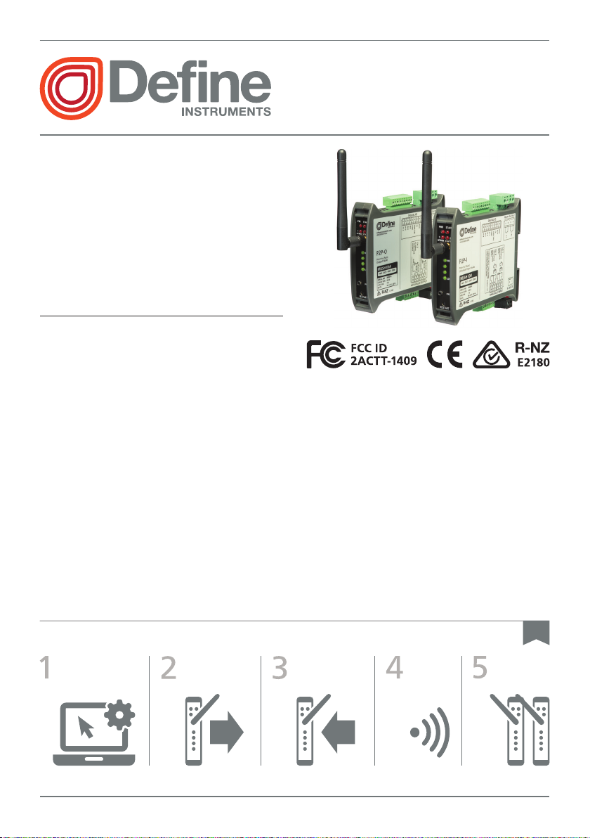
2.1 - Front Panel
A Network Status LED's
See 2.2 for denitions
B Antenna Jack
C Wireless Link Quality LED's
See 2.3 for denitions
D USB Programming Jack
See 6.2 for connection instructions
E Restart Button
See 2.4 for more information
2.2 - Network Status LED's
LED State Denition
PWR On Power supplied
STACK Flashing Node is transmitting or receiving
NTWRK
STATUS 1
NTWRK
STATUS 2
On Output node is booting
Flashing Output node is searching for a network
On Input node is booting
Flashing Input node is searching for a network
P2P-MAN-17V01 (0504)Copyright © 2017 Dene Instruments
Page 8

8
Input
Node
Output
LED State Denition
NTWRK
STATUS
1&2
Both On Units not paired. Check that all P2P nodes are powered on and
Both Flashing
Toggling Wireless network successfully established - ready to transmit or receive
in range, and that line-of-sight is uninterrupted. (See 12.2 for
Troubleshooting.)
P2P-I & P2P-R:
P2P-O: Max available nodes has been reached
Cannot connect to the network
2.3 - Wireless Link Quality LED's
The green Wireless Link Quality LED's are
used to indicate the quality of the wireless
connection between nodes.
HIGH indicates 100% link quality, while LOW
indicates approximately 80% link quality (i.e.
80% of the receiving packet intact.) For the
most stable and reliable wireless connection, the link quality should be at HIGH, or
as close to it as possible.
In a network with one or more Repeaters,
each node indicates the link quality between
itself, and the nearest node that it can reach
in the direction of the Output node.
2.4 - Restart Button
The Restart button can be used to reboot
the node in the event of a malfunction. (This
action is the same as turning the power
on and o again - all user settings will be
retained.)
For example, in the network below:
› The Input node indicates quality of link C
› Repeater 2 indicates the quality of link B
› Repeater 1 indicates the quality of link A
› The Output node indicates the quality of
link A
Repeater
2
C
B
Repeater
1
Node
A
To prevent accidental use, the Restart
button is inset and can only be pressed with
a ne-tipped, blunt instrument, such as a
pen or small screwdriver.
P2P-MAN-17V01 (0540) Copyright © 2017 Dene Instruments
Page 9

9
3
QUICK START
1 - Congure your system using ToolBox
The Twin Link is dispatched from the factory with the default input type
of 4–20mA, and all Setpoints set to Transparent Mode (see 10.1). If you
wish to keep the defaults, you can skip to Step 2 now. To change your
input type, output scaling or setpoint conguration:
A Install Dene ToolBox (see Section 5).
B Connect the Input node (P2P-I) to your computer using the USB
Bridge Key (see 6.2). Then launch ToolBox and click the 'Connect' button (see 6.3).
C Congure your system as required, referring to 6.3–6.5 in this manual,
and also the Help Panel in the soware. You may like to wire your
Input and Output nodes now, using the diagrams in the Help Panel
as a guide.
D When you are nished conguring your system, click 'Disconnect' in
ToolBox, and then disconnect the Input node from your PC.
Note that it is usually not necessary to connect the Output node or the
Repeater to your PC, unless the Wireless Transmit Power or Mesh ID needs
to be adjusted (see 6.5).
2 - Install Output node
If possible, your Output node (P2P-O) should be powered up rst when
setting up your Point-to-Point system.
A Install the Output node (P2P-O) in an enclosure at the output location
(see 4.3).
B Supply power to the node (see 8.2).
C Wait until the NTWRK STATUS 1 and NTWRK STATUS 2 LED's (2.1A)
start toggling. This indicates that the network has been successfully
created, and the unit is ready to connect to other nodes.
D Wire your analog outputs (see 8.3). You may also wire your digital IO's
and relays now, if desired (see Section 10).
The analog outputs will briey output 3mA when the node is powered up or restarted. They will then output a 3.6mA fault signal until
a successful link with an Input node (P2P-I) is established.
P2P-MAN-17V01 (0504)Copyright © 2017 Dene Instruments
Page 10
10
3 - Install Input node
A Install the Input node (P2P-I) in an enclosure at the input location
(see 4.3).
B Supply power to the node (see 9.2).
C Referring to 9.3A–9.3G, wire the two input channels as required for
your application. You may also wire your digital IO's and relays now, if
desired (see Section 10).
4 - Check connectivity
A Please wait at least 2 minutes aer powering up the Input node for
the wireless connection to be made. When a link has been successfully established, the NTWRK STATUS 1 and NTWRK STATUS 2 LED's
(2.1A) on the Input node will start toggling.
If the NTWRK STATUS LED's do not change from ashing to toggling,
then a connection cannot be established, and one or more Repeater
nodes may be needed (see Step 5, below).
B Check the 4 green Wireless Signal LED's on the Input node (P2P-I),
to establish link quality (see 2.3). If the link quality is low, then one or
more Repeater nodes may be needed (see Step 5, below).
5 - Add Repeaters
If a successful link cannot be established between the Input and Output
nodes, or the link quality is low, then one or more Repeater nodes can
be added.
Note that for a successful wireless connection (using the included 3DBi
antenna), all nodes must be within a range of 0.9mi (1.5km) LOS. If line
of sight is impeded by buildings or topography, the transmission distance
must be reduced until a strong signal can be obtained.
A Install each Repeater (P2P-R) in an enclosure at a location that is in
line of sight from any nodes it will communicate with (see 4.3).
B Supply power to the node (see 11.2).
C Provided the Mesh ID of the Repeater is a match to the Input and
Output nodes, the Repeater will be automatically detected and in-
cluded into the network. (See 11.3 for more about the Mesh ID).
P2P-MAN-17V01 (0540) Copyright © 2017 Dene Instruments
Page 11
11
5.75" (146mm)
(150mm
)
4
HARDWARE INSTALLATION
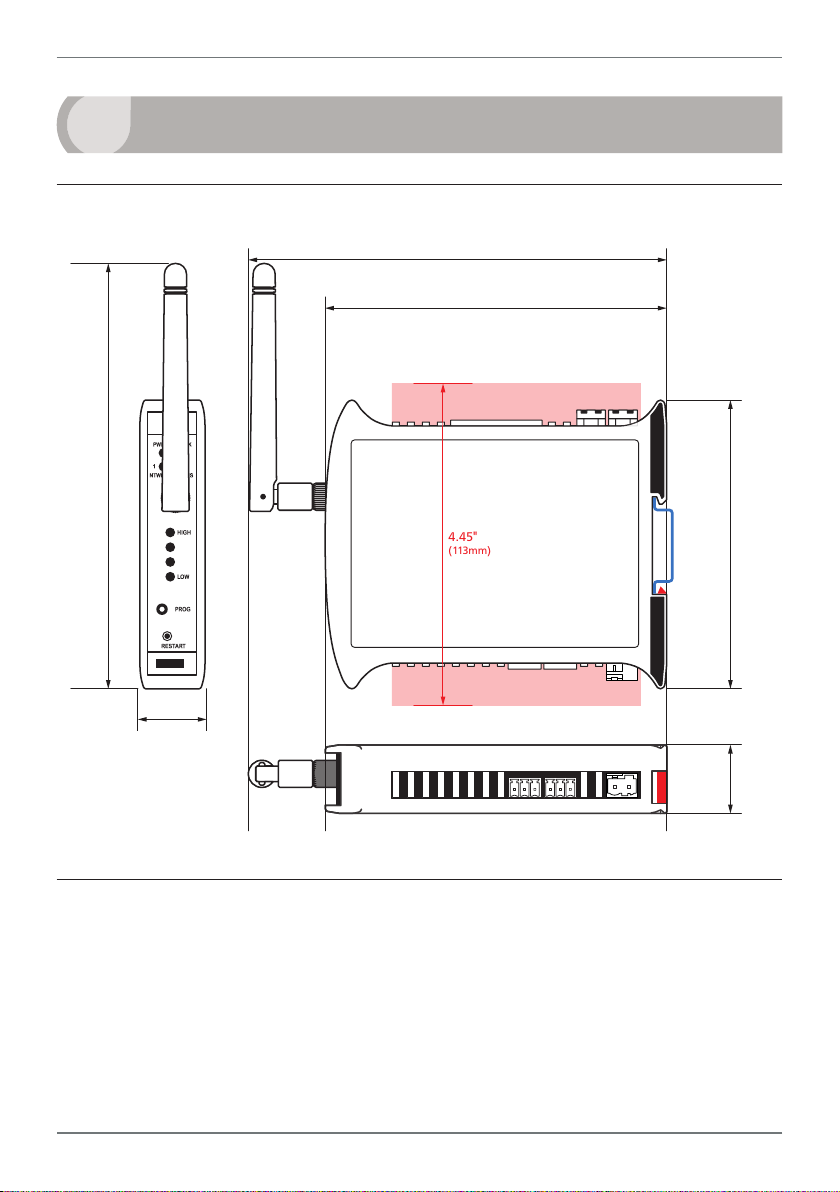
4.1 - Case Diagram
5.91"
)
4.72" (120mm)
Terminals with Connectors in
4.45"
(113mm)
Terminals with Connectors in
35mm
DIN
Rail
3.98"
(101mm
0.91"
(23mm)
4.2 - Installation Environment
Twin Link nodes should be installed in locations that do not exceed the maximum operating temperature, and at a safe distance
from other devices that generate excessive
heat. The installation environment should
provide good air circulation to the unit.
0.91"
(23mm)
The plastic casing and product label may be
cleaned, if required, using a so, damp cloth
and neutral soap product.
Caution should be exercised when cleaning
the unit to avoid water to dripping inside, as
this will damage the internal circuits.
P2P-MAN-17V01 (0504)Copyright © 2017 Dene Instruments
Page 12
12
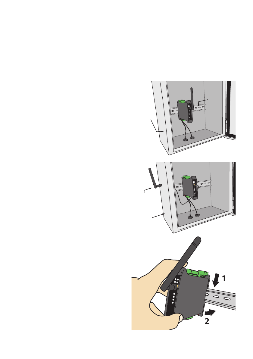
Antenna mounted
outside enclosure
using antenna
extension cable
4.3 - Installation Instructions
Dene Instruments P2P nodes are rated IP20. Nodes should be mounted in protective enclosures, to protect them from weather conditions and dust.
For a successful wireless link to be made, each P2P node must be located at a distance of
no more than 0.9mi (1.5km) LOS from other nodes that it will communicate with. If using
the WG-8DBI antenna, this distance may be
increased to 4km (2.5mi) LOS.
A - Plastic Enclosure (Fig 1)
Prepare the Plastic Enclosure (not supplied)
as illustrated by mounting a DIN 35 rail, cable
glands, and any other required components.
The antenna may be mounted directly on
the P2P unit (inside the Plastic Enclosure).
B - Metal Enclosure (Fig 2)
Prepare the Metal Enclosure (not supplied)
as illustrated by mounting a DIN 35 rail, cable
glands, and any other required components.
This enclosure type should be earthed.
A Metal Enclosure will impede wireless
signal strength if the antenna is mounted internally. In this case, the antenna must be installed on the outside of the enclosure, using
the WG-AEC Antenna Extension Cable (sold
separately).
C - DIN Rail Mounting (Fig 3)
To clip the unit onto the DIN rail:
(1) Hook the upper part of the unit onto the
rail, and then (2) Press down towards the rail
until the red hook clicks into place.
Leave at least 0.8" (2cm) clear on either
side of the unit, and at least 2" (5cm) clear
above and below the unit, to allow room
for airow and wiring.
Plastic
enclosure
Metal
enclosure
35mm
DIN rail
Fig 1
Fig 2
D - Wiring
Refer to Sections 7–11 in this manual.
P2P-MAN-17V01 (0540) Copyright © 2017 Dene Instruments
Fig 3
Page 13

E - Removal from DIN Rail (Fig 4)
The unit may be unclipped from the DIN rail
if required by inserting a small screwdriver
into the slot on the red hook (just visible
when the unit is mounted), and levering the
red hook down.
This will release the hook, allowing the unit
to be detached from the DIN rail.
4.4 - EMC Installation Guidelines
13
Fig 4
All products in the P2P series have been
designed to cope with large EMC disturbances. This has been achieved by continual
testing and improvement of ltering and
layout techniques over many years.
P2P nodes meet CE noise requirements,
and even surpass them in many tests. (For
full details and test results, see Appendix
A.) However in some applications with less
than optimum installations and large power
switching, the EMC performance of a P2P
node can be further improved, by:
A Installing the node in an earthed Metal
Enclosure (see 4.3B). This is particularly
useful if the control box is mounted
close to large power switching devices
like contactors. Every switching cycle
there is a possibility of generating a
large amount of near eld radiated
noise. The Metal Enclosure, acting as a
faraday cage, will shunt this radiation to
ground and away from the P2P node.
Further improvements can be made
with this type of noise by increasing the
physical distance from the power devices. For example, increasing the control
box distance from 6" to 12" from the
noise source will reduce the noise seen
by the control box by a factor of 4. Probably the cheapest and best results in this
situation could be obtained by adding
RC snubbers to the contactors or power
switches.
B Using shielded cable on sensitive input
and control signal lines. Good results can
be obtained by grounding the shields to
the metal enclosure close to the entry
point. All cables act as aerials and pick
up unwanted R.F. radiated signals and
noise; the earthed shield acts as a faraday cage around the cables, shunting
the unwanted energy to ground.
Shields can also help with capacitively
coupled noise typically found in circumstances when signal cable is laid on top
of noisy switching power cables. Of
course in this case you are better o to
keep separate signal and power lines.
C Laying cable on earthed cable trays can
also help reduce noise seen by the P2P
node. This is particularly useful if there
are long cable runs, or the unit is close
to radiating sources such as two way
radios.
D The relay outputs of the P2P-I and
P2P-O nodes have built in MOV's to help
reduce EMI when switching inductive
loads. EMI can further be reduced at the
load by adding snubbers for AC signals
or a yback diode for DC coils.
P2P-MAN-17V01 (0504)Copyright © 2017 Dene Instruments
Page 14

14
5
ToolBox oers a smart, no-fuss setup experience for your Twin Link Point-to-Point system, and
has been designed to simplify and speed up conguration.
You must install ToolBox before connecting the Twin Link to your computer. If you have
already connected your Input node using the Bridge Key, please disconnect before continuing.
A Download the latest version of ToolBox from
www.deneinstruments.com/toolbox
For ease of access, we recommend saving the install le on your desktop. If you cannot locate
the install le, check whether your browser has saved it in your Downloads folder.
B Extract the install le from the zip folder. Right-click on the zip folder and choose 'Extract
All', (or extract the le using another extraction utility of your choice).
SOFTWARE INSTALLATION
C Double-click on the extracted .msi install
le. This will launch the ToolBox installer.
Depending on your security settings, a
'Security Warning' dialogue may appear.
If you see the security message, click
'Run'.
P2P-MAN-17V01 (0540) Copyright © 2017 Dene Instruments
Page 15

D The ToolBox setup wizard will
launch.
Click 'Next' to get started.
E The wizard will also ask for
conrmation that you wish
to begin the installation.
Click 'Next' to continue.
F The wizard will prompt you to
select an installation folder.
You may accept the default
installation folder, or select
an alternative location by
clicking 'Browse'.
Click 'Next' to continue.
G The install wizard will now
install ToolBox.
Please wait. This process usually takes 2-3 minutes, but
may take longer in some
situations.
15
H When the installation has suc-
cessfully completed, the following dialogue will appear.
Click 'Close' to exit.
The installer will place an icon
on your desktop for easy access to ToolBox.
The downloaded .zip and
.msi installer les are no longer needed, and may be deleted if desired.
P2P-MAN-17V01 (0504)Copyright © 2017 Dene Instruments
Page 16

16
6
SOFTWARE CONFIGURATION USING TOOLBOX
6.1 - Before You Start
Soware setup of your Twin Link network is facilitated through the Input node (P2P-I), and
there is usually no need to connect your Output (P2P-O) or Repeater (P2P-R) to your computer:
Node to Connect to ToolBox Congurable Options
Input Node P2P-I All input, output and setpoint settings
Output Node P2P-O Wireless Transmit Power ON LY (see 6.5)
Repeater Node P2P-R Mesh ID & Wireless Transmit Power ON LY (see 6.5)
Mesh ID & Wireless Transmit Power (see 6.5)
Install the ToolBox soware (see Section 5) before connecting the Input Node to your PC.
6.2 - Bridge Key
Connect the Input Node (P2P-I) to your computer's USB port using the Bridge Key, and supply
power to the unit. The interface cable connects to the USB programming jack on the unit's
front panel (see 2.1D). A USB extension cable is supplied for your use if required - this is oen
used for convenience in accessing USB ports located at the back of the computer.
CAUTION - Risk of damage
Ensure that all connections between
the Bridge Key and your P2P node
are secure.
Attempting to connect when cables
P2P-I
Input Node
are not rmly pushed in may result
in connection faults, and could also
cause damage to the unit or your PC.
Interface
Cable
USB Bridge Key
PC Connection
INSTALL SOFTWARE FIRST!
P2P-MAN-17V01 (0540) Copyright © 2017 Dene Instruments
9−36V DC
Power Supply
USB Extension Cable
(If Necessary)
Page 17
17
6.3 - Using ToolBox
Dene ToolBox enables full conguration of your Twin Link system. To set up your
Point-to-Point network, you only need to plug in the P2P-I. Other nodes generally
do not require soware conguration (see 6.1).
ToolBox features a comprehensive help panel that will guide you through the setup of your
Twin Link. Helpful hints and explanations will appear when you adjust a setting using the
ToolBox controls.
There are four main navigation pages/tabs:
› Overview: General info about the connected node, Mesh ID and regional settings
› Input/Output: Input mode/range, Scaling/offset, Retransmission scaling
› Setpoints: Setpoint mode for digital IO's, including activation points and smart modes
› Advanced: Load/save configuration, Create configuration certificate
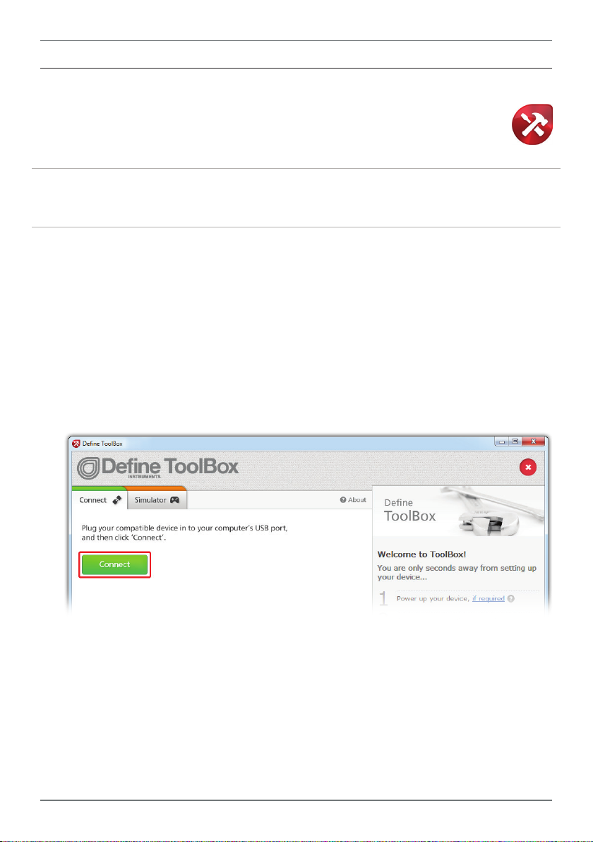
A Connect the P2P-I to your computer using the Bridge Key as shown in 6.2.
Supply power to your P2P-I node as shown in 9.2.
B Double-click the ToolBox icon on your desktop to launch the ToolBox program.
C Click the green 'Connect' button. This will scan your computer's Com ports and
automatically connect to your device.
Connection problems?
ToolBox will auto-detect and connect to any connected P2P node when you click the 'Connect'
button. If you have problems establishing a connection, please check the following:
› Ensure that all connections between the device and your computer are secure.
› Ensure that 9–36V DC is being supplied to the connected node.
› Try disconnecting and reconnecting the USB, or using a different USB port on your PC.
› Disconnect any additional compatible devices. The software's auto-detect feature will not
work if multiple compatible devices are connected to your computer at the same time.
P2P-MAN-17V01 (0504)Copyright © 2017 Dene Instruments
Page 18

18
6.4 - ToolBox Interface Overview
Main Navigation Tabs
Overview, Input/Output, Setpoints, and Advanced conguration pages.
Control Area
Main control area for conguring your
system. Any changes made in this area will
bring up the Apply Bar (see below)
Connection Panel
Disconnect button
Connection status
Apply Bar
Appears if you have made any changes in the
Control Area. ToolBox will not allow you to browse
to a new tab in the Main Navigation with unapplied changes to your conguration.
P2P-MAN-17V01 (0540) Copyright © 2017 Dene Instruments
Help Panel
Diagrams, explanations, and
helpful tips will automatically
appear in this panel as you
congure your unit.
Page 19

19
6.5 - Mesh ID, Wireless Transmit Power
Mesh ID and Wireless Transmit Power are the only two settings that must be congured individually for each P2P node. Because of this, they are also the only settings that require you to
connect to your Output node (P2P-O) or your Repeater (P2P-R) using the ToolBox soware.
(All other settings are congured by connecting the Input node [P2P-I].)
Mesh ID
Each P2P node has a Mesh ID code, which
is printed on the product label. This 16-digit
code is used to link the node to other nodes
in the network.
The Mesh ID of the Output node is considered the 'parent' ID of the network, and
cannot be edited.
The Mesh ID of the Input node is matched
to the Output node by the manufacturer,
prior to dispatch. In the event of a fault requiring replacement of one of the Twin Link
nodes, the Mesh ID of the Input node may
be edited. This can be done on the 'Overview' page in Dene ToolBox.
The Mesh ID of any Repeater node(s) used
must also match that of your Twin Link. Any
Repeater nodes that you order with your
Twin Link will be Mesh ID matched by your
distributor, so there is usually no need to
congure this setting.
If additional Repeater nodes are added at a
later stage, then you may need to set them
to match the Mesh ID of the Twin Link pair
(see 11.3 for instructions).
A Repeater that has a clear line of sight to
other in-range nodes, with a matched Mesh
ID, will be automatically incorporated into
the network.
Wireless Transmit Power
The Wireless Transmit Power setting oers
a selectable list of regions. Selecting the
region in which the P2P network will be
used, will set the transmission power of the
node to comply with local regulations.
Region Transmission Power Complies With
New Zealand & Australia +20dBm (100mW) AS/NZS 4268:2012
USA +20dBm (100mW) FCC Part 15.247
South Africa +10dBm (10mW) ETSI EN 300 440-2
Europe +10dBm (10mW) ETSI EN 300 440-2
IMPORTANT
Regional regulations may have changed since manufacture of this product or publication of
this manual. It is the responsibility of the assembler of the system to ensure that the system
fully complies with all local codes and requirements.
Note that each node in the system must be
individually set for the correct region, by
connecting the node to Dene ToolBox, selecting the region, and then clicking 'Apply'.
P2P-MAN-17V01 (0504)Copyright © 2017 Dene Instruments
Page 20

20
Label Side (Right)
DIN
7
Electrical connections are made via plug in
terminal blocks on the top and bottom of
P2P nodes. All conductors must conform to
the unit's voltage and current ratings, and
be suitably rated for the expected temperature range to be incurred.
When wiring your P2P nodes, check all connections against the terminal numbers printed on the label, and the appropriate wiring
diagrams in this manual (Sections 8–11) or
the Dene ToolBox soware.
Strip the wire, leaving around 0.25" (6mm)
of bare lead exposed. If you are using
stranded wire, this should be tinned with
solder. Insert the lead into the correct plug
in the correct position, and tighten until the
wire is secure. Verify tightness by pulling on
the wire.
Follow all local codes and regulations when
wiring and installing your P2P node.
WIRING GUIDELINES
3.5mm Terminals
See 8.1B–C, 9.1B–C & 10.2E–F
The smaller 3.5mm terminals, (used for the
channel inputs, analog output and Digital
IO), are rated to accept one wire from #14
AWG (2.5mm) to #28 AWG. However it is
possible to accept up to four #28 AWG wires.
5mm Terminals
See 8.1A, 9.1A, 10.2D & 11.2
The larger 5mm terminals, (used for the
power and relay outputs), are rated to
accept one wire from #14 AWG (2.5mm)
to #20 AWG. However it is also possible to
accept two #18 AWG wires, or up to four
#20 AWG wires.
8
OUTPUT WIRING
8.1 - P2P-O Bottom View
Rail
A Power supply
(9–36V DC)
(See 8.2, Pins 20–21)
P2P-MAN-17V01 (0540) Copyright © 2017 Dene Instruments
B Analog output
CH 1 (4–20mA)
(See 8.3, Pins 1–3)
C Analog output
CH 2 (4–20mA)
(See 8.3, Pins 4–6)
Page 21

8.2 - Power Supply
See 8.1A, Pins 20–21
Supply 9–36V DC to the Output node (P2P-O) as shown (right).
9−36V DC
Power
Supply
21
8.3 - Analog Output
See 8.1B, Pins 1–3 (CH1), and 8.1C, Pins 4–6 (CH2)
Wire your two analog output channels, referring to the diagrams in this
section and the terminal numbers for each channel, as printed on the
product label. (The diagram below gives a more detailed example of how
to wire the two analog outputs for current loop output.)
The analog outputs will briey output 3mA when the Output node
(P2P-O) is powered up or restarted.
They will then output a 3.6mA fault signal until a successful link with an
Input node (P2P-I) is established. The analog outputs can be scaled to suit
your application using the ToolBox soware connected to the Input node
(P2P-I, see Section 6).
Analog Output Wiring for Current Loop Output
CH 2
4–20mA
+24V
External
Supply
CH 1
4–20mA
+24V
4−20mA
Analog Output
Exernal
supply & load
CH1
CH2
RL
Load
Meter/PLC Meter/PLC
P2P-MAN-17V01 (0504)Copyright © 2017 Dene Instruments
Page 22

22
Label Side (Right)
DIN
9
INPUT WIRING
9.1 - P2P-I Bottom View
A Power supply
(9–36V DC)
(See 9.2, Pins 20–21)
B Input CH 1
(See 9.3, Pins 1–3)
9.2 - Power Supply
See 9.1A, Pins 20–21
Supply 9–36V DC to the Input node (P2P-I) as shown (right).
C Input CH 2
(See 9.3, Pins 4–6)
9−36V DC
Power
Supply
Rail
9.3 - Input
See 9.1B, Pins 1–3 (CH1), and 9.1C, Pins 4–6 (CH2)
The P2P-I has two universal input channels which accept a wide range of input types. Input
specications and wiring for all available P2P-I input types can be found below (9.3A–9.3G).
CAUTION
Risk of electric shock. Dangerous and lethal voltages may be present on the terminals of
the unit. Please take appropriate precautions to ensure safety.
CAUTION
Risk of danger. The sensor input can potentially oat to dangerous and unexpected volt-
ages depending on what external circuit it is connected to. Appropriate considerations
must be given to the potential of the sensor input with respect to earth common.
P2P-MAN-17V01 (0540) Copyright © 2017 Dene Instruments
Page 23

9.3A - Thermocouple Input
23
Thermocouple types
B, E, J, K, N, R, S, T
Input impedance >500KΩ min
TC lead resistance 100Ω max
Temperature (thermocouple)
The thermocouple is one of the most
common temperature sensors used in
industry. It relies on the Seebeck coecient between dissimilar metals.
The thermocouple type is selected with
reference to the application temperature range and environment. The most
common thermocouple types for general
purpose applications are J and K type.
Thermocouple
Cold junction comp. -10 to 60°C
CJC dri <0.02°C/C typical for all inputs
Sensor open Upscale
Accuracy 0.1% of FSO±1°C typical
Supported thermocouple types/ranges
K -328 to 2300°F (-200 to 1260°C)
B 752 to 3272°F (400 to 1800°C)
E -328 to 1292°F (-200 to 700°C)
J -328 to 1832°F (-200 to 1000°C)
R 32 to 3092°F (0 to 1700°C)
S 32 to 3092°F (0 to 1700°C)
T -328 to 752°F (-200 to 400°C)
N -328 to 2372°F (-200 to 1300°C)
9.3B - RTD Input
RTD types
Pt100 (3-wire RTD DIN 43760:1980) or
Pt1000 (3-wire RTD standard)
Resolution for each calibrated range
-328–572°F (-200–300°C) = 0.02°F (0.01°C)
-328–1472°F (-200–800°C) = 0.1°F (0.1°C)
Sensor current 0.6mA continuous
Lead resistance 10Ω/lead max
recommended
Sensor fail Upscale
Accuracy
-328–572°F (-200–300°C) = ±0.1°C
-328–1472°F (-200–800°C) = ±0.3°C
Ambient dri 0.003°C/C typical
P2P-MAN-17V01 (0504)Copyright © 2017 Dene Instruments
Page 24

24
Temperature (RTD)
The RTD (standing for Resistance
Temperature Device) is highly stable and
accurate, and is fast becoming the most
popular temperature sensor in industry.
Oen referred to as Pt100 and Pt1000,
the Pt represents platinum (the dominant
metal in its construction), and 100/1000 is
the resistance in ohms at 0°C.
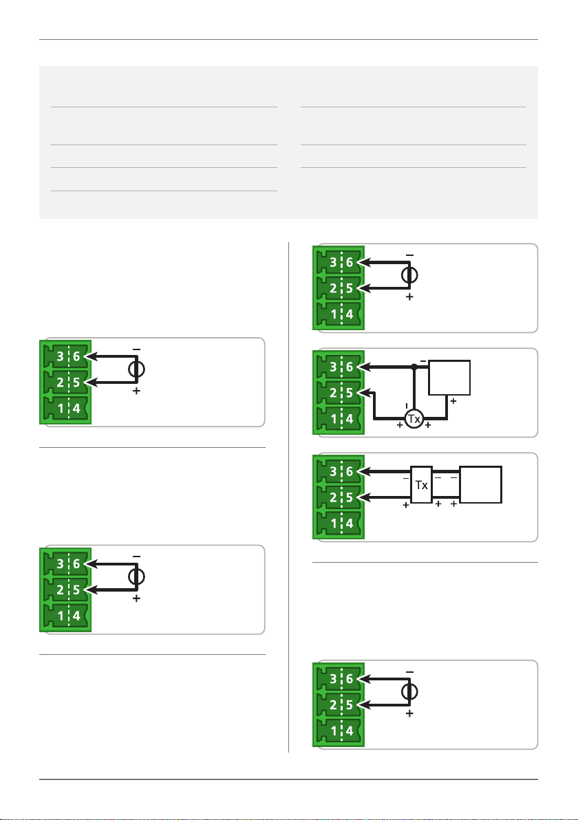
9.3C - Current Input
RTD 3 Wire
Pt100/1000
Supported RTD types/ranges
Pt100/
Pt1000
-328 to 572°F (-200 to 300°C)
-328 to 1472°F (-200 to 800°C)
Range 0/4–20mA
Input resistance 45Ω
Max over-range Protected by PTC to
24V DC
Linearity & repeatability 0.1% FSO max
0/4–20mA DC
0/4–20mA DC is the most commonly
used analog signal in industry, and is
universally accepted. As a current loop,
it is unaected by voltage drops in
cables, and can be transmitted over long
distances without signal degradation.
Current
0/4–20mA
Accuracy 0.1% FSO max
Channel separation 0.001% max
Ambient dri <50ppm/°C of FS input
Response 100msec
External
Output
Output
Output
+24V
Supply
2 Wire
Loop Powered
Transmitter
4–20mA
External
+24V Supply
Output
3 Wire
Transmitter
0/4–20mA
External
+24V
Supply
4 Wire Transmitter
0/4–20mA
P2P-MAN-17V01 (0540) Copyright © 2017 Dene Instruments
Page 25
9.3D - Voltage Input
25
Ranges ±200mV, –200mV to 1V,
0–10V, 0–18V
Input impedance >500KΩ on all ranges
Maximum over-voltage 24V DC
Accuracy 0.1% FSO max
±200mV DC
For low signal applications the P2P-I supports a ±200mV DC range. Typical applications include measuring large DC currents
using external current shunts.
–200 to 200mV DC
-200mV to 1V DC
A -200mV to 1V range is provided for
interfacing to sensors and other electronic apparatus that provide this output.
Linearity and repeatability
0.05% FSO max
Channel separation 0.001% max
Ambient dri 0.003%/°C
0–10V DC
External
+24V
Supply
Output
Output
Output
Output
External
4 Wire Transmitter
0–10V DC
3 Wire
Transmitter
0–10V DC
+24V
Supply
–200mV to 1V DC
0–10V DC
0–10V DC is a common process signal
generated by transmitters, meters and
PLCs. It would normally be scaled into
engineering units by the P2P-I.
0–18V DC
This is a general purpose voltage measuring range, typically used to measure battery voltages, power supply outputs etc.
0–18V DC
P2P-MAN-17V01 (0504)Copyright © 2017 Dene Instruments
Page 26

26
9.3E - Digital Pulse
Frequency range 0–2500Hz
Sensors Open collector (NPN, PNP)
Frequency resolution 0.1Hz
General frequency mode
General Frequency mode allows an NPN
or PNP input (up to 2.5KHz) to be measured and scaled to any engineering unit.
Flow rate mode
Flow Rate mode enables an input from an
NPN or PNP paddle type ow meter to be
converted to a ow rate. The input signal
(up to 2.5KHz) is converted into a ow
rate by programming the unit with the
sensor manufacturer's K-factor value.
RPM mode
ToolBox RPM mode enables an input from
an NPN or PNP proximity sensor to be
converted to an RPM (Revs Per Minute)
value. The input signal (up to 2.5KHz) is
converted into RPM by programming the
unit with the pulses per revolution value.
Soware modes General frequency, Flow
rate, or RPM
Accuracy ± 0.5%
NPN open collector output
NPN Open
Collector
Output
PNP open collector output
PNP Open
Collector
Output
9.3F - Potentiometer Input
Potentiometer input 3-wire
Potentiometer resistance
Low range (<2KΩ) or High range (>2kΩ)
Excitation voltage Variable
Field programmable zero 0–90% of span
P2P-MAN-17V01 (0540) Copyright © 2017 Dene Instruments
Field programmable span 0.1–100%
Linearity and repeatability
<±0.05% FSO typical
Response time 100msec
Temperature dri <50ppm/°C
Page 27

27
ACCS Jump Ranges
200A
010/420:
420-L:
3 wire potentiometer
A 3 wire potentiometer is typically used to measure position. The low or high potentiometer
range can be programmed to your unit using the ToolBox soware. These ranges must be
calibrated using the two point calibration method.
Potentiometer
Low (<2kΩ)
9.3G - AC Current Sensor
Sensor type Current transformer
ACCS-420, ACCS-420-L and ACCS-010
Header selectable amperage range
ACCS-420/010 = 100/150/200A
ACCS-420-L = 10/20/50A
Overload (continuous)
ACCS-420/010 = 175/300/400A respectively
ACCS-420-L = 80/120/200A respectively
Isolation voltage 2,000V
Accuracy 1% of full scale
AC current sensors
The unit accepts input from a Dene
Instruments AC current sensor. Set the
jumper on the top of the sensor to the
desired current range, as shown (below).
Potentiometer
High (>2kΩ)
Output (Representing 0–100% of full scale
input range)
ACCS-420(-L) = 4–20mA DC loop powered
ACCS-010 = 0–10V DC
Power supply
ACCS-420(-L) = Loop powered, 15–36V DC
ACCS-010 = Self powered
Response time 250ms (10–90%)
Frequency 50–60Hz
External
24V DC
Supply
AC
Current
Sensor
AC Current
Sensor
4–20mA
0–100A
0–10A
0–150A
0–20A
0–
0–50A
AC
Current
Sensor
P2P-MAN-17V01 (0504)Copyright © 2017 Dene Instruments
AC
Current
Sensor
0–10V
Page 28
28
Label Side (Right)
DIN
Rail
10
DIGITAL I/O'S & RELAYS
10.1 - Overview
Each digital IO and relay output is mapped to a corresponding channel on the opposite point,
depending on the Setpoint Mode selected during initial setup using Dene ToolBox. There
are three soware modes that may be selected:
Transparent Mode
In Transparent Mode, each relay or digital
output on the Output node is controlled by
its corresponding digital input on the Input
node, and vice versa.
This is ideal for the transfer of slow pulses
through the air to PLC's and SCADA systems,
or for manual remote control of appliances
and machines.
It is recommended that you congure your setpoints in Dene ToolBox (see Section 6) before
continuing with wiring your digital IO's and relays. Once soware setup is complete and you
have decided exactly how each setpoint will be used,
to the terminal numbers printed on the product label.
Alarm or Control Mode
Alarm Mode is ideal for tripping alarms or
for alerting an operator to key system conditions. Control Mode is designed to control
other equipment (such as turning pumps
and heating units on and o).
In both Alarm & Control modes, the input
channels control the relays and digital outputs on both the Input and the Output
nodes.
wire them as shown below, referring
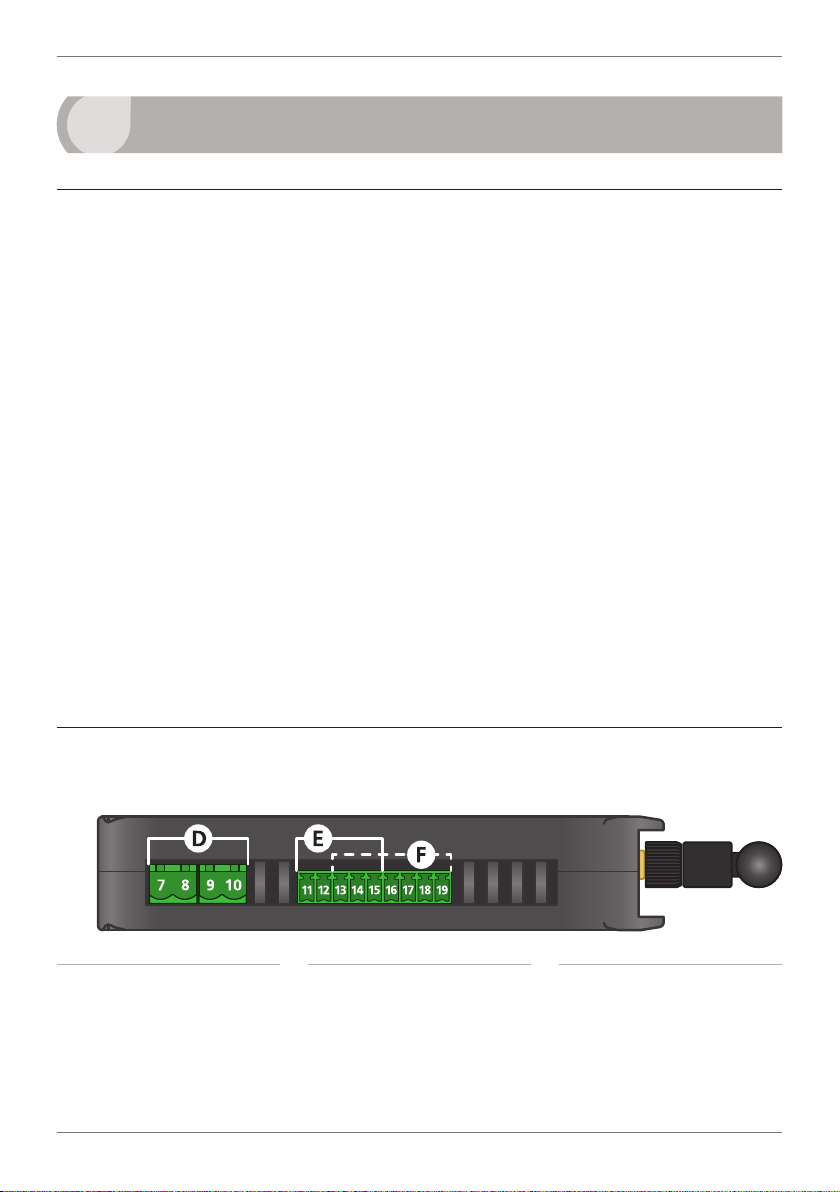
10.2 - P2P-I & P2P-O Top View
D Relay Outputs
(See 10.3, Pins 7–10)
P2P-MAN-17V01 (0540) Copyright © 2017 Dene Instruments
E Digital Outputs
(See 10.4, Pins 11–12, 15)
F Digital Inputs
(See 10.5, Pins 13–19)
Page 29

10.3 - Relay Outputs
Relay Outputs
R2R1
See 10.2D, Pins 7–10
Wire your two relay output channels as shown (right), referring to the
terminal numbers for each channel as printed on the product label.
In Transparent Mode:
› R1 is controlled by D1 of the opposite node.
› R2 is controlled by D2 of the opposite node.
In Alarm or Control Mode:
› R1 and R2 are controlled by Input CH1, and mimicked from the
Input node to the Output node.
10.4 - Digital Outputs
See 10.2E, Pins 11–12 & 15
Wire your two digital output channels as shown (right),
referring to the terminal numbers for each channel as
printed on the product label.
In Transparent Mode:
› DO3 is controlled by D3 of the opposite node.
› DO4 is controlled by D4 of the opposite node.
In Alarm or Control Mode:
› DO3 and DO4 are controlled by Input CH2, and
mimicked from the Input node to the Output node.
DO3
DO4
Digital Outputs
29
GND
10.5 - Digital Inputs
See 10.2F, Pins 13–19
Wire your two digital output channels as shown (right),
referring to the terminal numbers for each channel as
printed on the product label.
In Transparent Mode:
› D1 controls R1 of the opposite node.
› D2 controls R2 of the opposite node.
› D3 controls DO3 of the opposite node.
› D4 controls DO3 of the opposite node.
In Alarm or Control Mode:
› D1–D4 may be programmed for various other functions using ToolBox, but are not
linked to any of the outputs.
3V
GND
SINK/SRC
P2P-MAN-17V01 (0504)Copyright © 2017 Dene Instruments
D1
D2
D3
Digital Inputs
D4
Page 30

30
11
REPEATER NODE
11.1 - Overview
The Point-to-Point Repeater is the perfect
addition to a Twin Link system where the
Input and Output nodes are out of range,
or a line of sight connection is interrupted by
buildings or hilly terrain. It works by retransmitting incoming signals from other nodes
in the network, enabling you to boost your
range and navigate around obstacles.
A Repeater will extend the range of your
Twin Link by up to 0.9mi (1.5km) LOS using
the supplied antenna. Add up to 15 repeaters in a single Point-to-Point system, and
that’s a wireless transmission distance of up
to 14.9mi (24km).
11.2 - Supply Power
Pins 20–21
Supply 9–36V DC to the Repeater node (P2P-R) as shown (right). The power
terminal is located on the underside of the P2P-R, and is the only wiring terminal on the unit.
Wait up to two minutes, and then check the NTWRK STATUS LED's on the
front of the Repeater unit. If the LED's start toggling, then the Repeater has
successfully integrated with your Twin Link, and no further setup is required.
If the NTWRK STATUS LED's do not start toggling aer waiting a few minutes, and you are
sure that all P2P units are in range and line of sight, please see 11.3.
9−36V DC
Power
Supply
11.3 - Check the Mesh ID
Connections between P2P nodes are established using a Mesh ID code (see 6.5). If you
ordered your Repeater with a Twin Link,
then all of the Mesh ID's should have been
matched by your distributor, and it is not
necessary to continue with 11.3.
If the Mesh ID's are not yet matched, or you
are having diculty pairing a Repeater and
would like to check the Mesh ID:
A Supply power to your Repeater (P2P-R),
and then connect the node to your computer using the Bridge Key (see 6.2).
P2P-MAN-17V01 (0540) Copyright © 2017 Dene Instruments
B Launch Dene ToolBox and click
'Connect'.
C ToolBox will display the 'Overview' pan-
el. Check the Mesh ID number against
the number printed on your Twin Link.
If required, edit the Mesh ID number
and then click 'Apply'.
D Disconnect from ToolBox.
E Once the Mesh ID’s are matched, and
all units in the system are in range and
line of sight, the new node will be automatically included in the network.
Page 31

31
12
MAINTENANCE
12.1 - Calibration
Your P2P units have been fully calibrated at the factory, and can be recalibrated in soware
using Dene ToolBox (see 6.3 to connect). Scaling to convert the input signal to a desired
display value is also done using ToolBox.
If your P2P unit appears to be behaving incorrectly or inaccurately, refer to troubleshooting
before attempting to calibrate it. When recalibration is required (generally every 2 years), it
should only be performed by qualied technicians using appropriate equipment.
Calibration does not change any user programmed parameters. However, it may aect the
accuracy of the input signal values previously stored.
12.2 - Troubleshooting
Issue Resolution
Input & Output nodes are
not pairing
Repeater node(s) are not
pairing
Output node outputs 3mA
continuously
Output node outputs
3.6mA continuously
Check that both nodes are powered up, in range, and line
of sight.
Check that the Mesh ID's printed on the labels are identical.
If they are dierent, set the Mesh ID of the Input node to
match the Output node, referring to 6.5.
Check that all nodes in the network are powered up, in
range, and line of sight.
If this is not the issue, then the Mesh ID of the Repeater
needs to be set. Please see 11.3.
This is a fault signal, which indicates that the units are not
paired. Check that all units are powered up, in range, and
line of sight. You may need to add a Repeater node to
achieve a wireless link (see 11.1).
This is a fault signal, which indicates that the network link
has been broken. Check the power to the Input node, and
check that the RF surrounding has not changed. If the quality of the wireless link is low (see 2.3), you may need to add
a Repeater, use to a higher power antenna, or reposition
your node(s).
For further assistance, please contact technical support using the contact details listed at the
end of this document.
P2P-MAN-17V01 (0504)Copyright © 2017 Dene Instruments
Page 32

32
A
APPENDIX A - EMC TEST RESULTS
Statement of compliance
The Dene Instruments Point 2 Point (P2P) Remote Monitoring Transceiver complies with EN
301 489-3 V1.6.1–2013 when tested in accordance with EN 301 489-1 V1.9.2 2011 as a base
station.
Results summary
The results from testing carried out in August 2014 are summarized in the following table.
Phenomena Application Results
Radiated emissions Enclosure Not applicable
Conducted emission DC Power input/output ports Complies
Conducted emission AC Mains input/output ports Not applicable
Harmonic current
emissions
Voltage uctuations
& icker
Conducted emissions Telecom port Not applicable
RF Electromagnetic
eld 80–2700MHz
Electrostatic discharge Enclosure Complies
Fast transients,
common mode
RF Common mode
0.15–80MHz
Transients & surges DC Power input ports Not applicable
Voltage dips &
interruptions
Surges common &
dierential mode
AC Mains input/output ports Not applicable
AC Mains input port Not applicable
Enclosure Complies
Signal, telecom & control
ports, DC & AC power ports
Signal, telecom & control
ports, DC & AC power ports
AC Mains power input ports Not applicable
AC Mains power input &
telecom ports
DC supply cable will not exceed 3 metres
in length
DC powered device
DC powered device
Device does not have a telecom port
Complies
Complies
Device is not used in a vehicle
DC powered device
Not applicable
DC powered device with no telecom port
P2P-MAN-17V01 (0540) Copyright © 2017 Dene Instruments
Page 33

33
B
APPENDIX B - WARRANTY
Warranty
Dene Instruments warrants that its products are free from defects in material and
workmanship under normal use and service for a period of one year from date of
shipment.
Dene Instruments’s obligations under
this warranty are limited to replacement or
repair, at its option, at its factory, of any
of the products which shall, within the applicable period aer shipment, be returned
to Dene Instruments’s facility, transportation charges pre-paid, and which are, aer
examination, disclosed to the satisfaction of
Dene Instruments to be thus defective.
User’s Responsibility
We are pleased to oer suggestions on the
use of our various products, by way of printed matter, on our website, or through direct
contact with our sales/application engineering sta.
However, since we have no control over the
use of our products once they are shipped,
NO WARRANTY, WHETHER OF MERCHANTABILITY, FITNESS FOR PURPOSE OR OTHERWISE is made beyond repair, replacement, or
refund of purchase price at the sole discretion of Dene Instruments.
Users shall determine the suitability of the
product for the intended application before
The warranty shall not apply to any equipment which shall have been repaired or
altered, except by Dene Instruments, or
which shall have been subjected to misuse,
negligence or accident.
In no case shall Dene Instruments’s liability exceed the original purchase price. The
aforementioned provisions do not extend
the original warranty period of any product
which has been either repaired or replaced
by Dene Instruments.
using, and the users assume all risk and liability whatsoever in connection therewith,
regardless of any of our suggestions or statements as to application or construction.
In no event shall Dene Instruments’s liability, in law or otherwise, be in excess of the
purchase price of the product.
Dene Instruments cannot assume responsibility for any circuitry described. No circuit
patent or soware licenses are implied.
Dene Instruments reserves the right to
change circuitry, operating soware, specications, and prices without notice at any
time.
P2P-MAN-17V01 (0504)Copyright © 2017 Dene Instruments
Page 34

34
P2P-MAN-17V01 (0540) Copyright © 2017 Dene Instruments
Page 35

35
P2P-MAN-17V01 (0504)Copyright © 2017 Dene Instruments
Page 36

De ne Instruments
New Zealand
(Head O ce)
Auckland 0632, New Zealand
Auckland 0661, New Zealand
Ph
Fax
www.de neinstruments.co.nz
10B Vega Place, Rosedale,
PO Box 245 Westpark Village,
: +64 (9) 835 1550
: +64 (9) 835 1250
sales@de neinstruments.co.nz
Twin Link Revision Code: P2P-MAN-16V05 Date Code: 160920
United States (Dallas, TX)
Ph: (214) 926 4950
sales@de neinstruments.com
www.de neinstruments.com
South Africa (Pretoria)
sales@de neinstruments.co.za
www.de neinstruments.co.za
 Loading...