


1
TEX-PRC
Process Controller
The TEX-PRC process controller interfac-
es smoothly with a wide range of PLC
and monitoring systems. Specically for
use in process applications, it accepts
0–20mA, 4–20mA, 0–2V or 0–10V
inputs.
This controller has been designed for
ease of use, with intuitive, scrolling text
prompts that guide you step-by-step
through the setup process. The front
panel includes 5 buttons, for simple
operator interface, and a 6-digit LED
display.
Order Codes
TEX–PRC 4–20mA/0–10V Controller
–HV
–LV
Options
–R2
–R4
–A 1 x mA/V analog output
–S2R 1 x RS232 (RJ11 terminal)
–S4S 1 x RS485 (screw terminal)
85–265V AC / 95–370V DC
15–48V AC / 10–72V DC
2 x relay outputs
4 x relay outputs
Contents
1 - Specications ............................. 2
2 - Front Panel & Display ................ 3
3 - Wiring ......................................... 4
4 - Dimensions & Installation ......... 8
5 - Input Header Adjustment ....... 10
6 - Input Setup & Calibration ....... 12
7 - Setpoint Setup ......................... 18
8 - Setpoint Open Access .............. 21
9 - Reset PIN Numbers / View
Firmware Version ..................... 21
A - Appendix A - Serial Modes ...... 22
TEX-PRC-MAN-19V01 (0219) Copyright © 2019 Dene Instruments

2
1
SPECIFICATIONS
Input
Input signal Current (0–20mA /
4–20mA) or Voltage (0–2V / 0–10V)
Excitation 24V DC (50mA max)
Sampling rate 10Hz
Resolution 16-bit
Accuracy 0.05% of reading
Ambient dri Typically 50ppm/°C
Power
Power supply
HV: 85–265V AC/95–370V DC, or
LV: 15–48V AC/10–72V DC
Relay Output
OPTIONAL
Programming
Front panel buttons Up, Down, P
(Prog/Enter), plus 2x Function Buttons
for menu access
Calibration Factory set up for 4–20mA.
Calibrated for 0/4–20mA and 0–2/10V.
Simple header adjustment required for
voltage input (see Section 5)
Security Input setup and setpoint functions have independent PIN code access
Display
Display type LED display, 5 buttons
LED indicators 6 setpoint LEDs
Digits 1 row of 6 digits, 13mm (0.5")
size, 14-segment alphanumeric LED
Number of relay outputs 0, 2, or 4
Construction
Relay output type 5A Form A (3A 240V
AC max or 3A 30V DC max)
Analog Output
Number of analog outputs None or 1
Analog output type Isolated 16 bit
4–20mA/0–10V
TEX-PRC-MAN-19V01 (0219) Copyright © 2019 Dene Instruments
OPTIONAL
Casing Panel mount case, 5 buttons
Ingress protection rating IP65 dust/
splash proof (face only)
Dimensions (H x W x D)
48 x 96 x 120mm (1.89 x 3.78 x 4.72")
Cutout area (H x W)
45 x 92mm (1.77 x 3.62")
3
2
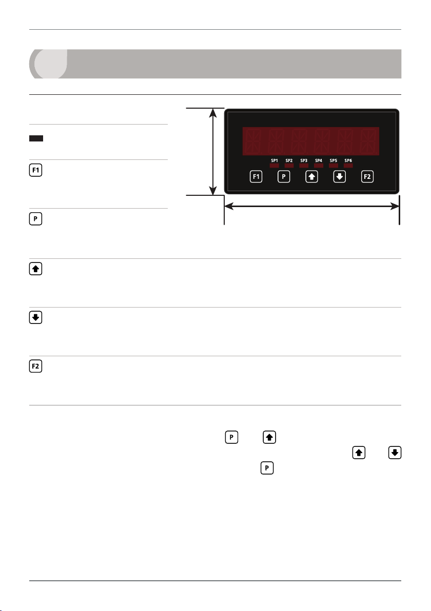
FRONT PANEL & DISPLAY
2.1 - Front panel
SPX
The SP LED's are used to
indicate active setpoints.
This button is used to
access the Input Setup &
Calibration menu (Section 6).
This button is used to save
your settings and advance
to the next step in the setup process.
This button is typically used to scroll through options or increase values in the
setup menu. Pressing this button from the main display allows you to view/reset the
PEAK value (see 2.3).
This button is typically used to scroll through options or decrease values in the
setup menu. Pressing this button from the main display allows you to view/reset the
VALLEY value (see 2.3).
48mm
(1.89")
96mm (3.78")
This button is used to access the Setpoint Setup menu (Section 7) and the
Setpoint Open Access menu (Section 8).
2.2 - Display brightness
To adjust the display brightness, press the and buttons together from the
main display. BRI appears and toggles with the current setting. Use the and
buttons to adjust the LED backlight, and then press to nish.
TEX-PRC-MAN-19V01 (0219) Copyright © 2019 Dene Instruments
4
2.3 - Up and down button shortcuts
Pressing the and buttons from the main operational display allows instant
access to peak and valley values held in the controller's memory, as shown below.
PEAK Maximum measured process input since the unit was turned on or reset
VALLEY Minimum measured process input since the unit was turned on or reset
PEAK or VALLEY may be reset to zero by pressing the and buttons at the
same time while the variable is being displayed. These values may also be reset using
the function pins (see 3.6). Press at any time to return to normal operating mode.
3
WIRING
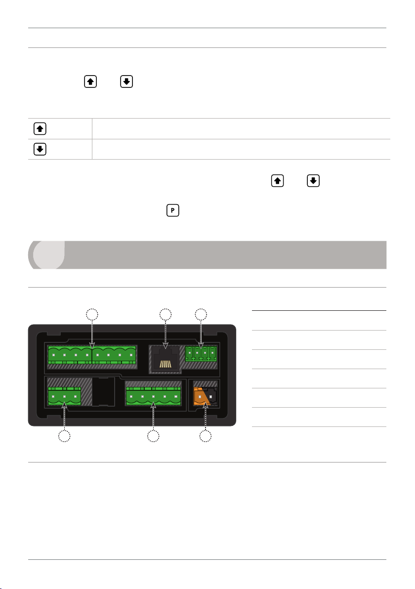
3.1 - Pinouts
A B C
D
E
F
Key
3.1A Relay Output (See 3.3)
3.1B Serial Port (See 3.5)
3.1C Analog Output (See 3.4)
3.1D Analog Input (See 3.2)
3.1E Function Pins (See 3.6)
3.1F Power Supply (See 3.7)
3.2 - Wire the analog input See 3.1D
The analog input module has an input type header that is congured for 0/4–20mA
input by default. This will need to be adjusted for voltage input applications.
Ideally you should do this before you continue wiring. Please see Section 5.
TEX-PRC-MAN-19V01 (0219) Copyright © 2019 Dene Instruments
5
+ POS
+ Signal
+ POS
N/C
+ Signal
+ POS
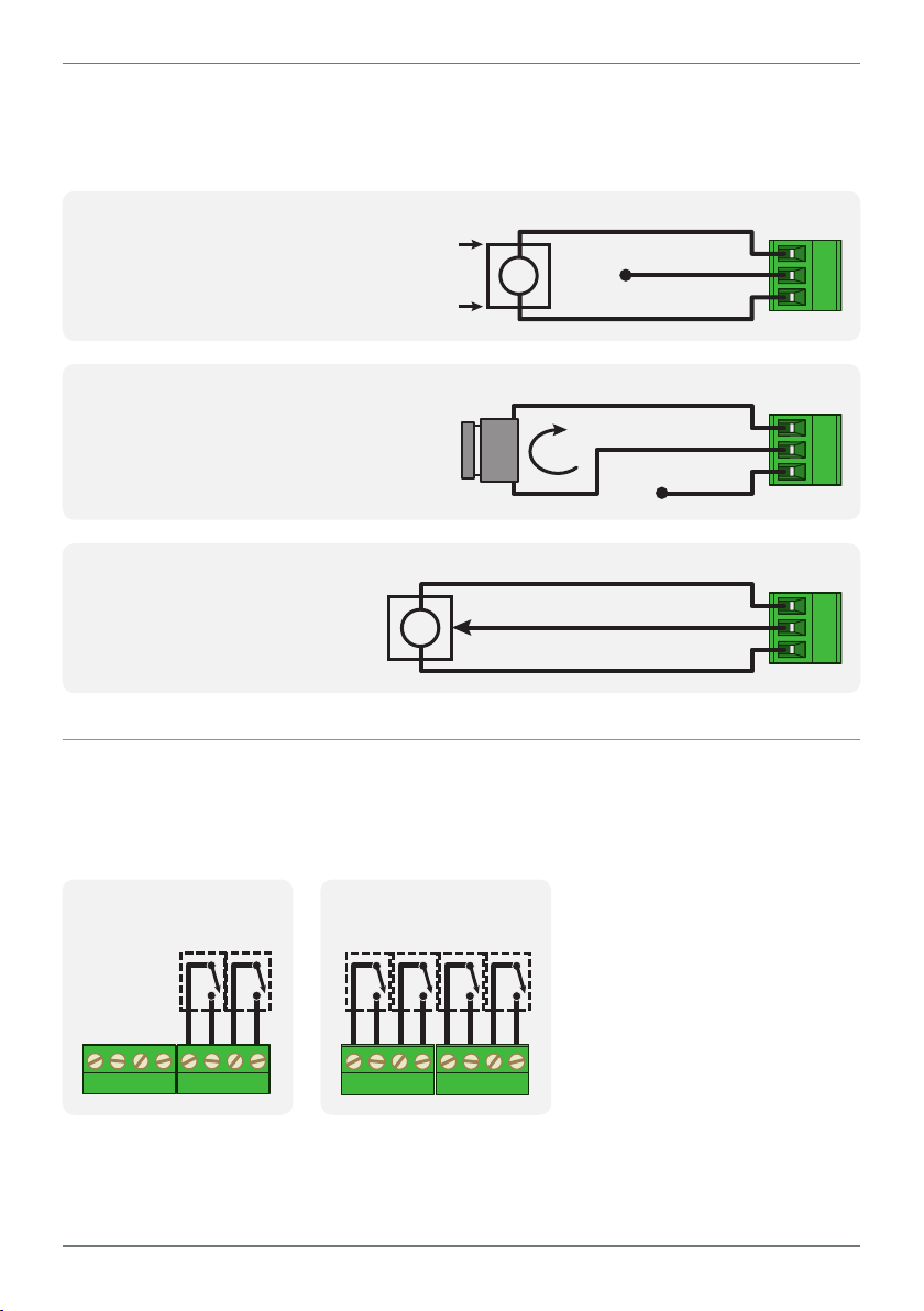
Then wire the analog input as required for your application, referring to the
diagrams below.
2-wire Current/Voltage Input
External excitation used
+ Supply
EXTERNAL
-
Supply
I /V
-
Signal
N/C
+ 24V EXC
-
NEG
2-wire Current Input
Loop powered sensor
SENSOR
I
+ 24V EXC
-
NEG
3-wire Current/Voltage Input
Controller supplied excitation
I /V
+ Supply
-
Signal
/ - Supply
+ 24V EXC
-
NEG
3.3 - Wire the relay outputs See 3.1A
If your controller has relay outputs tted, wire them as shown below. Relays can be
programmed to operate within the total span range of the controller.
-R2
SP2 SP1
-R4
SP3SP4 SP1SP2
TEX-PRC-MAN-19V01 (0219) Copyright © 2019 Dene Instruments
6
+mA
Valley Tes tEnergy
Peak
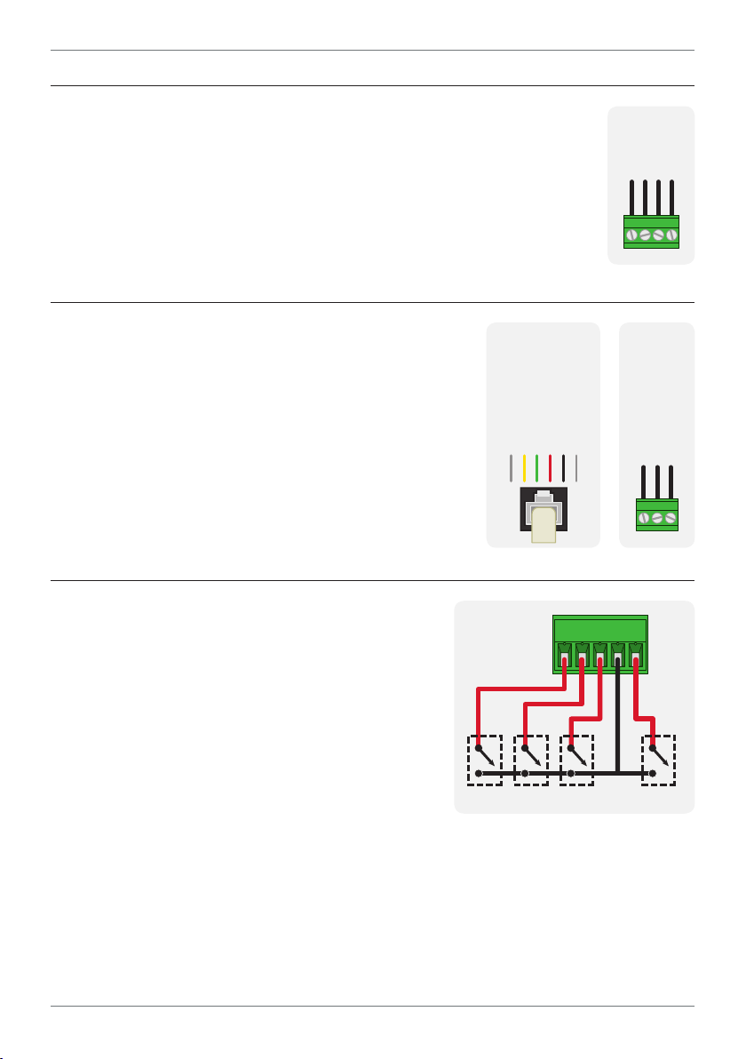
3.4 - Wire the analog output
See 3.1C
If your controller has analog output tted, wire it as shown for either
voltage (0–10V) or current (4–20mA).
3.5 - Serial port
N/C
-S2R
SGND
+5V DC (option)
RXD
TXD
See 3.1B
If your controller has serial port tted, wire it as shown
in the applicable diagram. (S2R: RS232, RJ11 terminal,
S4S: RS485, screw terminal).
3.6 - Wire the function pins
See 3.1E
N/C
-A
–V+V–mA
-S4S
D -D +
SGND
Connect external switches to enable a function
to be executed when its switch is activated:
Valley Clears the Valley value (also see 2.3)
Hold Holds the current display value
Tes t Resets the meter
Peak Clears the Peak value (also see 2.3)
TEX-PRC-MAN-19V01 (0219) Copyright © 2019 Dene Instruments
COM
7
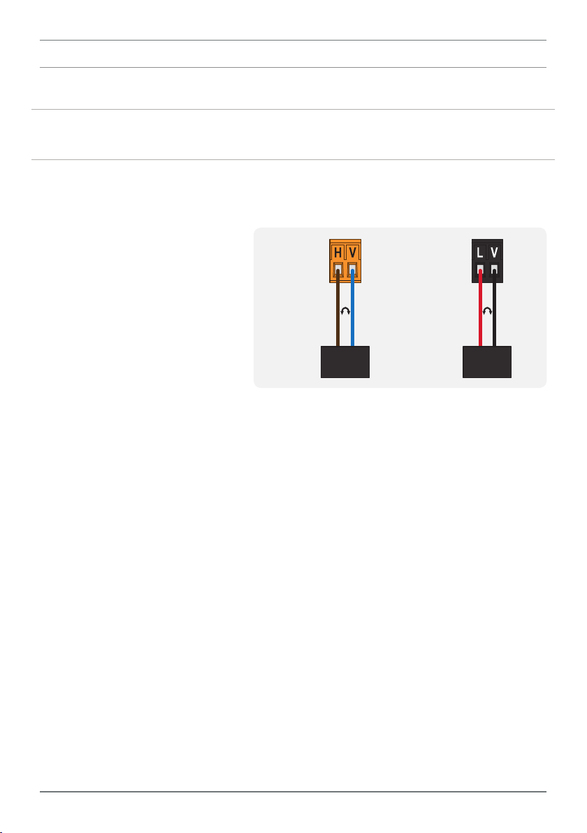
3.7 - Wire the power supply See 3.1F
DO NOT attempt to wire your controller while the power is on. NEVER connect your
low voltage controller to mains power.
Wire your controller for low or high voltage power supply, as show in the diagrams
below. Check the label on the unit against the colour of the connector:
› Orange =
High voltage (85–265V AC,
95–370V DC)
› Black =
Low voltage (15–48V AC,
High
voltage
(HV)
+DC
Live
AC
−DC
Neutral
AC
Low
voltage
(LV)
+DC
Live
AC
−DC
Neutral
AC
10–72V DC)
HV power
supply
LV power
supply
Once you have completed the wiring process it is safe to switch on your power
supply. Ensure that your display is functioning before you proceed.
TEX-PRC-MAN-19V01 (0219) Copyright © 2019 Dene Instruments
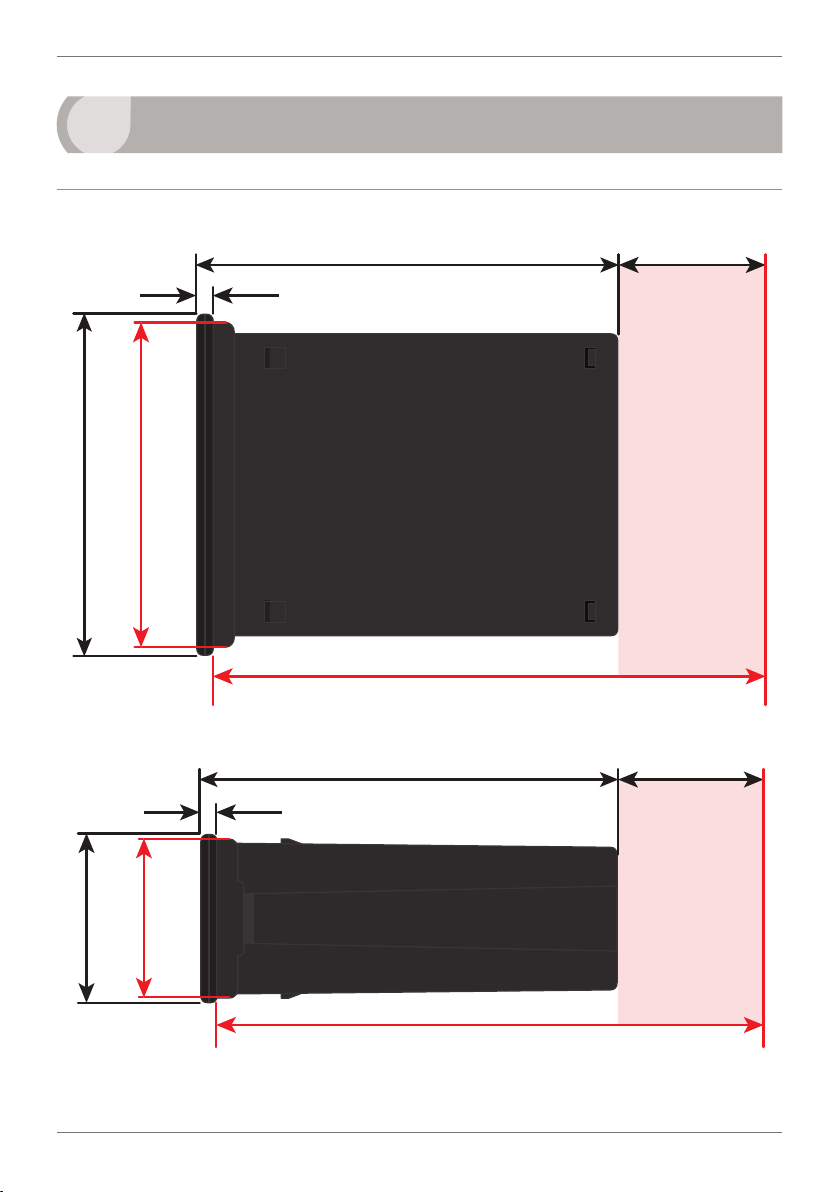
8
120
39
155mm (6.10") minimum depth required behind panel
4
DIMENSIONS & INSTALLATION
4.1 - Case dimensions
mm (0.16")
4
96
mm
92mm
(3.78")
(3.62")
mm (4.72")
mm (1.54")
Cabling
Allowance
155mm (6.10") minimum depth required behind panel
120 mm (4.72") 39mm (1.54")
mm (0.16")
4
mm
45mm
48
(1.89")
(1.77")
TEX-PRC-MAN-19V01 (0219) Copyright © 2019 Dene Instruments
Cabling
Allowance
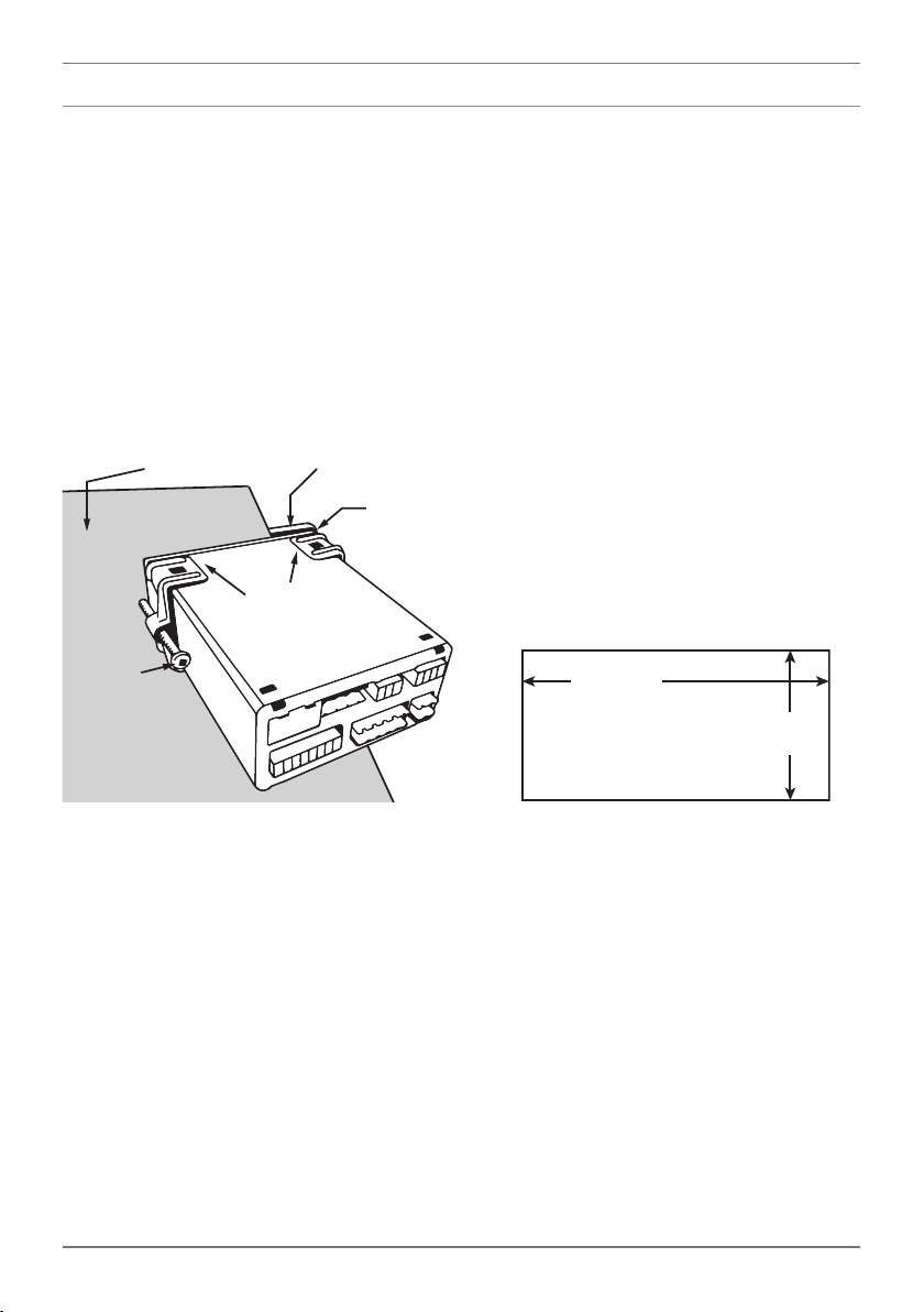
4.2 - Installation instructions
Panel Meter Faceplate
Panel Cutout
9
A Prepare the Panel Cutout to
92 x 45mm ±.5 (3.62 x 1.77" ±.02),
as shown below.
Allow at least 155mm (6.10")
depth behind the panel to accommodate the meter body, protruding connectors and cabling.
B Remove the Mounting Clips from
the meter back.
Panel
Gasket
Mounting
Clips
Screws
C Slide the Panel Gasket over the
rear of the unit to the back of the
Meter Faceplate.
D From the front of the panel, insert
the meter into the Panel Cutout.
Holding the unit in place, engage
the Mounting Clips so that the tabs
snap into place over the notches on
the case.
E To achieve a proper seal, tighten
the Screws evenly until the unit sits
rmly against the panel. Do not
over-tighten the screws.
92mm ±.5
(3.62″ ±.02)
45mm ±.5
(1.77″ ±.02)
TEX-PRC-MAN-19V01 (0219) Copyright © 2019 Dene Instruments

10
5
The analog input board for the TEX-PRC has a header which can be set to 3 positions,
depending on your input type and range, as per the table below:
Header Position Used For
20mA 0–20mA and 4–20mA input ranges (default setting)
2V 0–2V input range
10V 0–10V input range
INPUT HEADER ADJUSTMENT
5.1 - Do I need to shi the input header?
In most cases the input header does not need to be changed from its default posi-
tion of '20mA' (suitable for 0–20mA and 4–20mA inputs).
You will need to shift the input header if:
› You are using the 0–2V or 0–10V input range, or
› You are changing your input type back to mA after previous setup for voltage
5.2 - How to shi the input header
A If the meter is already installed, remove it from the panel, and unplug all plugs
from the back of the unit.
B Using a small screwdriver or similar implement,
press downward into one of the slots at the
rear of the case.
This will disengage the tab which holds the
back plate on, allowing it to be gently
levered away at one corner.
C Holding the loosened corner open
with one hand, disengage the le-
ver on the opposite slot.
TEX-PRC-MAN-19V01 (0219) Copyright © 2019 Dene Instruments

D You should now be able to remove
DC IP Module(IP07)
the back plate. If it does not unclip
easily, you may need to disengage
the two remaining tabs by repeat-
ing steps 5.2B–C on the other side
of the meter.
E Slide the analog input module out
of the meter case. (See 3.1D to
identify the input module.)
F Position the header on the input
module as required for your input
type and range:
20mA
Custom
2V
10V
11
› 20mA 0–20mA & 4–20mA
224E 2006 ©
› Custom Not used
› 2V 0–2V
› 10V 0–10V
Note that you will also need to change the Input Mode in soware from the front
panel - see 6.2C.
G Slide the input module back into the meter case.
Make sure that it is sitting in the tracks on the le and right. Press rmly until the input module
is fully inserted and sits ush with the other boards that are visible from the back of the meter.
H Replace the back plate.
Begin by inserting the two lower tabs into the slots, and then position the upper tabs so that
they will not catch on the top lip of the meter case. Apply rm pressure until the back plate
clicks into place.
I Reconnect the plugs and return the meter to the panel installation.
Don't forget that once the unit is connected and powered up, you will need to
enter the Input Setup menu (6.2) and conrm that the correct Input Mode is
also selected (see 6.2C).
TEX-PRC-MAN-19V01 (0219) Copyright © 2019 Dene Instruments

12
6
INPUT SETUP & CALIBRATION
6.1 - Enter Cal PIN number
A Enter the calibration mode by pressing the button.
_ _ _ ENTER CAL PIN NUMBER scrolls across the display and toggles with 0. Use
the
press . If the correct PIN is entered, setup is started at 6.2.
If an incorrect PIN number is entered, _ _ _ INCORRECT PIN NUMBER – ACCESS
DENIED scrolls across the display and it returns to normal operating mode.
You will have the opportunity to change your PIN number at the end of this section
(6.7). If you have forgotten your PIN number, see Section 9.
and buttons to enter your security code (factory default '1'). Then
6.2 - Input setup
A _ _ _ INPUT SETUP scrolls across the display and toggles with SKIP. Press to
skip to 6.3, or the button and then to ENTER input setup.
B _ _ _ MAINS FREQUENCY scrolls across the display. Use the
to select 50HZ or 60HZ, and then press .
C _ _ _ INPUT MODE scrolls across the display and toggles with the currently
selected input mode. Use the
2V (0–2V) or 10V (0–10V). Then press .
Note that if you change the INPUT MODE in this step, then the input header on the analog
input module may also need to be changed. See Section 5 for more information.
D _ _ _ DECIMAL POINT POSITION scrolls across the display and toggles with
the current selection. Use the and buttons to select NO DP (no decimal
point), 0.1, 0.12, 0.123, or 0.1234, and then press .
E _ _ _ DISPLAY ROUNDING scrolls across the display and toggles with the select-
ed rounding. Using the
TEX-PRC-MAN-19V01 (0219) Copyright © 2019 Dene Instruments
and buttons to select: 4–20MA, 0–20MA
and buttons, select: NONE, 2, 5, or 10. Press .
and buttons

13
Rounding is quoted in display counts and is not inuenced by decimal point position. For example, if your input signal is 5.3mA, the display will show: 5.3 (for rounding=NONE), 5.4 (for
rounding=2), 5.5 (for rounding=5), or 5.0 (for rounding=10).
6.3 - Calibration
A _ _ _ CALIBRATION TECHNIQUE scrolls across the display and toggles with
SKIP. Press to skip to 6.4, or use the and buttons to select a calibration method: either AUTO, MANUAL, or S.G. (secic gravity). Then press .
¨ If you selected AUTO, complete steps 6.3B–D now.
¨ If you selected MANUAL, complete steps 6.3E–F now.
¨ If you selected S.G., complete steps 6.3G now.
¨ If you selected SKIP, skip to 6.4 now.
AUTO (key-in) calibration uses zero and span values to calculate the scale and oset. This is the
most accurate calibration method, but requires known low and high input signals (or the use
of a calibrator).
MAN The manual calibration procedure uses low and high display values, and is intended for
a pre-calibrated sensor with a known output range. (For example 4mA=0 and 20mA=1000.) It
does not require any input signals to be applied to the controller during calibration.
S.G. The specic gravity calibration procedure allows the user to enter a scale factor which is
used to compensate for changes in the specic gravity of dierent substances. This does not
constitute a full calibration and assumes that either an automatic or manual calibration has
been applied previously with the S.G. value set to 1.0.
Auto calibration
B _ _ _ APPLY LOW INPUT SIGNAL – – – – ENTER LOW DISPLAY VALUE scrolls
across and toggles with the current selection. Apply the required low input sig-
nal, and wait a moment for the signal to stabilise. Then, using the
and
buttons, enter your low display value, and press to accept and continue.
C _ _ _ APPLY HIGH INPUT SIGNAL – – – – ENTER HIGH DISPLAY VALUE scrolls
across and toggles with the current selection. Apply the required high input
signal, and wait a moment for the signal to stabilise. Then, using the
and
buttons, enter your high display value, and press .
TEX-PRC-MAN-19V01 (0219) Copyright © 2019 Dene Instruments

14
D If Auto calibration was successful, you will be directed out of the calibration
menu to the operational display without viewing any further scrolling messages. (To proceed to step 6.4, you must select SKIP at 6.3A.)
If calibration fails, _ _ _ CALIBRATION FAILED will scroll across the display and
you will be directed back to the operational display. The most likely cause of this
error is that the controller could not detect any change in input signal during
calibration. Check your signal and connections, and repeat the procedure.
Manual calibration
E _ _ _ ENTER DISPLAY VALUE FOR [LOW MA/V] scrolls across the display, and
toggles with the current low display value. Use the
and buttons to adjust
the display value for the low level input signal. Then press .
The text string for [LOW MA/V] is determined by your INPUT MODE (selected in 6.2C):
0MA (for 0–20mA), 4MA (for 4–20mA) or 0V (for 0–2V/0–10V).
F _ _ _ ENTER DISPLAY VALUE FOR [HIGH MA/V] scrolls across the display, and
toggles with the current high display value. Use the and buttons to adjust
the display value for the high level input signal. Then press .
The text string for [HIGH MA/V] is determined by your INPUT MODE (selected in 6.2C):
20MA (for 0/4–20mA), 2V (for 0–2V) or 10V (for 0–10V).
Manual calibration is now complete. You will be directed back to the operational display. (To proceed to step 6.4, you must select SKIP at 6.3A.)
Specic gravity
G _ _ _ SPECIFIC GRAVITY scrolls across and toggles with the current specic
gravity scale factor. Adjust this value using the
and buttons, and then
press to accept and return to the operational display.
(To proceed to step 6.4, you must select SKIP at 6.3A.)
The specic gravity calibration procedure allows the user to enter a scale factor which is used
to compensate for changes in the specic gravity of dierent substances. This does not consti-
tute a full calibration and assumes that either an automatic or manual calibration has been
applied previously with the S.G. value set to 1.0.
TEX-PRC-MAN-19V01 (0219) Copyright © 2019 Dene Instruments

6.4 - Averaging
Input signal in counts
Sampling
Your controller has input signal averag-
ing, optimising stable measurement.
If the change in input exceeds the
averaging window value it will not
average, ensuring fast response when
there are large dierences between
readings.
Input exceeds
averaging window
Number
of samples
Averaging window
in displayed counts
15
A _ _ _ AVERAGING PARAMETERS scrolls across and toggles with SKIP. Press
to skip to 6.5, or the button and then to ENTER averaging setup.
B _ _ _ AVE SAMPLES scrolls across the display and toggles with the currently
selected averaging. Using the
and buttons, alter the number of input
samples that the controller will average, and then press .
Increasing the number of samples will stabilise measurement, but it will also slow down response rates. A typical value is 4.
C _ _ _ AVE WINDOW scrolls across the display and toggles with the currently
selected averaging window value. Using the and buttons, alter the signal
averaging window. Then press .
If your input signal contains large noise spikes, you can increase the size of the averaging window to ensure that these are still averaged. However, increasing the window size too far will
reduce the ability of the controller to respond quickly to real changes in input signal. Setting
AVE WINDOW to 0 will give continuous averaging as per the selected averaging samples. A
typical value is 10% of your system capacity.
6.5 - Analog output setup
N.B. All new units are calibrated before shipping. Recalibration is only necessary if settings
are wiped or the unit's accuracy requires verication aer a long period of use. e.g. 1 year.
A _ _ _ ANALOG OUTPUT SETUP scrolls across the display and toggles with SKIP.
If your controller does not have analog output installed, (or you do not wish to
congure your analog output now), press to skip to 6.7. Otherwise, press
the button and then to ENTER analog output setup.
TEX-PRC-MAN-19V01 (0219) Copyright © 2019 Dene Instruments

16
B _ _ _ LOW SCALE VALUE FOR ANALOG OUTPUT scrolls across the display and
toggles with the currently selected low scale display value. Use the and
buttons to enter your cal low position, and then press .
C _ _ _ HIGH SCALE VALUE FOR ANALOG OUTPUT scrolls across the display and
toggles with the currently selected high scale display value. Use the
buttons to enter your cal high position, and then press .
D _ _ _ CALIBRATE ANALOG OUTPUT? scrolls across the display and toggles with
SKIP. Press
button and then to ENTER.
Factory analog output calibration is precisely set before shipping this instrument, and should not be adjusted unless advised by the manufacturer.
¨ If you selected ENTER, connect a mA or volt meter across the analog
output connector (see 3.1C), and then continue to 6.5E.
¨ If you selected SKIP, go to 6.7 now.
E _ _ _ CAL LOW ANALOG OUTPUT scrolls across the display and toggles with a
calibration number shown in internal units (around -16000). Press the
buttons until the multimeter displays your target low output (e.g. 4mA), then
press .
now to skip analog output calibration and continue to 6.7, or the
and
or
F _ _ _ CAL HIGH ANALOG OUTPUT scrolls across the display and toggles with a
calibration number shown in internal units (around 30000). Press the
buttons until the multimeter displays your target high output, then press .
Analog output calibration is now complete. The display will return to normal
operating mode.
or
6.6 - Serial setup
A _ _ _ SERIAL SETUP scrolls across the display and toggles with SKIP. If your unit
does not have a serial port installed, (or you do not wish to congure your serial
options now), please press to skip to 6.7.
TEX-PRC-MAN-19V01 (0219) Copyright © 2019 Dene Instruments

17
Otherwise, press the button and then to ENTER serial setup.
B _ _ _ SERIAL MODE scrolls across the display and toggles with the currently
selected serial mode. Using the
and buttons, choose either: ASCII (cus-
tom), MODBUS (RTU) or RNGR A (Ranger A), and then press .
C _ _ _ BAUD RATE scrolls across the display and toggles with the current selec-
tion. Use the
and buttons to select one of: 300, 600, 1200, 2400, 4800,
9600, 19200 or 38400. Then press .
D _ _ _ PARITY scrolls across the display and toggles with the current selection.
Using the
and buttons, select: NONE, ODD or EVEN, and then press .
E _ _ _ SERIAL ADDRESS scrolls across the display and toggles with the current
address. Use the
The serial address parameter is used to identify a particular device when it is used with other
devices in a system. (It applies particularly to MODBUS mode when used on an RS485 serial
network.) The serial address of the controller must be set to match the serial address dened
in the master device.
and buttons to alter the serial address, and press .
Refer to Appendix A for more information on serial modes and registers.
6.7 - Edit Cal PIN number
A _ _ _ EDIT CAL PIN NUMBER scrolls across the display and toggles with SKIP.
Press to skip and return to the operational display, or the button and
then to ENTER and change your PIN number.
B _ _ _ ENTER NEW CAL PIN NUMBER scrolls across the display and toggles
with the current PIN (default 1). Using the
calibration PIN number. Then press to exit to the operational display.
and buttons, enter your new
TEX-PRC-MAN-19V01 (0219) Copyright © 2019 Dene Instruments

18
7
The soware in your controller will allow you to congure up to 6 setpoints,
however full functionality is only supported when relay output hardware is
installed.
(Setpoints with no corresponding relay output hardware may be used as simple LED
indicators, if desired. In this case, features requiring relay output functionality will
continue to appear in the setup menu, but will be ignored by the controller.)
SETPOINT SETUP
7.1 - Enter Setpoint PIN number
A Enter setpoint setup mode by pressing and holding the button for 3 seconds.
_ _ _ ENTER SP PIN NUMBER scrolls across the display and toggles with 0.
Use the
Then press . If the correct PIN is entered, setup is started at 7.2.
If an incorrect PIN number is entered, _ _ _ INCORRECT PIN NUMBER – ACCESS
DENIED scrolls across the display and it returns to normal operating mode.
You will have the opportunity to change your PIN number at the end of this section
(7.3). If you have forgotten your PIN number, see Section 9.
and buttons to enter your security code (factory default '1').
7.2 - Setpoint setup
A _ _ _ EDIT SETPOINT scrolls across the display and toggles with SKIP. Press
now to skip to 7.3, or use the and buttons to select a setpoint to edit,
and then press .
B _ _ _ SP VALUE scrolls across the display and toggles with the current value for
the selected setpoint. Using the
which the selected setpoint will activate, and then press .
C _ _ _ SP ACTIVATION scrolls across the display and toggles with the current ac-
tivation for the selected setpoint. Using the
TEX-PRC-MAN-19V01 (0219) Copyright © 2019 Dene Instruments
and buttons, adjust the display value at
and buttons, select the relay

19
Energised Above
Energised Above
activation to operate ABOVE or BELOW the setpoint value, and then press .
ABOVE: Relay turns on above the setpoint value and o below it.
BELOW: Relay turns on below the setpoint value and o above it.
D _ _ _ SETPOINT TYPE scrolls across the display and toggles with the current
setting for the selected setpoint. Using the and buttons, select either
ALARM or CNTRL (control), and then press .
ALARM - SETPOINT VALUE controls setpoint
activation point. HYSTERESIS VALUE con-
trols setpoint deactivation point.
CNTRL - SETPOINT VALUE controls setpoint
deactivation point. HYSTERESIS VALUE con-
trols setpoint reactivation point.
Hysteresis
band
Hysteresis
band
Energised Below
Hysteresis
band
Hysteresis
band
Energised Below
E _ _ _ HYSTERESIS VALUE scrolls across the display and toggles with the hyster-
esis value for the selected setpoint. Use the and buttons to adjust this
value if required, and then press .
The HYSTERESIS VALUE denes the separation band between setpoint activation and deacti-
vation, and will operate as per the SETPOINT TYPE setting selected in 7.2D.
F _ _ _ MAKE DELAY scrolls across the display and toggles with the current make
delay time for the selected setpoint. This is the time delay between setpoint ac-
tivation, and when the relay turns on. Adjust this value in 0.1 second increments
using the and buttons, and then press .
G _ _ _ OPEN ACCESS TO SP VALUE scrolls across the display and toggles with the
open access permission setting for the selected setpoint. Use the
and to
select either YES or NO, and then press .
When enabled, this option allows the selected setpoint's value to be edited directly aer pressing the button, without needing to enter a PIN number or go through all of the other options. Each setpoint can individually have this option enabled or disabled. See Section 8.
H The step that you proceed to now will depend on which setpoint you are editing
(selected in 7.2A):
¨ If you are currently editing SP 1, skip to 7.2J now.
¨ If you are currently editing SP 2–4, continue to 7.2I now.
TEX-PRC-MAN-19V01 (0219) Copyright © 2019 Dene Instruments

20
I _ _ _ TRAIL SP1 scrolls across the display and toggles with the trailing setting for
the selected setpoint. A setpoint with TRAIL SP1 enabled will trail the SP Value
of SP 1. (The setpoint value of the trailing setpoint will eectively become an
oset value.)
Using the and buttons, turn trailing OFF or ON, and then press .
J _ _ _ EDIT SETPOINT scrolls across the display and toggles with SKIP. You are
now back at 7.2A. To edit another setpoint, follow the instructions from 7.2A–J
again. If you do not wish to edit another setpoint, press
now to skip to 7.3.
7.3 - Edit SP PIN number
A _ _ _ EDIT SP PIN NUMBER scrolls across the display and toggles with SKIP.
Press to skip and return to the operational display, or the button and
then to ENTER and change your PIN number.
B _ _ _ ENTER NEW SP PIN NUMBER scrolls across the display and toggles with
the current PIN (default 1). Using the
number. Then press to exit to the operational display.
and buttons, enter your new SP PIN
TEX-PRC-MAN-19V01 (0219) Copyright © 2019 Dene Instruments

21
8
If none of the setpoints have their open access option enabled then this feature will
be disabled and the
A Begin by pressing the
B The name of the rst access-enabled setpoint will appear on the display and
toggle with the current value for that setpoint. Using the
adjust the selected value. Then press to accept and continue.
C The name of the next access-enabled setpoint will appear on the display, along
with its setpoint value. Repeat step 8B. The open access menu will proceed
through all access-enabled setpoints in this fashion. Pressing
bled setpoint will exit and return to the operational display.
9
SETPOINT OPEN ACCESS
button will not respond to a short button press. (See 7.2G.)
button for less than 3 seconds.
and buttons,
for the last ena-
RESET PIN NUMBERS / VIEW FIRMWARE VERSION
If you have forgotten your PIN number(s), follow the procedure below to reset both
the Calibration and Setpoint PINs to their factory default of 1.
This procedure will also allow you to view the current soware installed on your
device, which may be required for support purposes.
A Press
execute and you may need several tries to get it right.)
B A message will appear on the display, with details of the unit's current soware
conguration (Product name, Firmware Version, and Macro Version etc). At the
end, you will see _ _ _ ALL PIN NUMBERS RESET TO 1.
C Both the Cal PIN number and the SP PIN number have now been reset to '1'.
You can change this, if required, by following the instructions in 6.7 (for Cal)
and 7.3 (for SP), using '1' to enter each menu initially.
, and at the same time. (This key combination can be dicult to
TEX-PRC-MAN-19V01 (0219) Copyright © 2019 Dene Instruments

22
A
APPENDIX A - SERIAL MODES
A.1 - Custom ASCII mode
Custom ASCII is a simple, custom protocol that allows connection to various PC con-
guration tools. ('Custom ASCII' diers from the 'Modbus (ASCII)' protocol used by
some devices.) Custom ASCII command strings must be constructed in this order:
<Start> <Controller Address> <Read/Write Command> <Register Address>
<Separator Character> <Data Value> <Message Terminator>
Start - Use 'S' for the start character of a command string (not case sensitive). This
must be the rst character in the string.
Controller Address - Use an ASCII number from '1' to '255' for the controller address.
If the character following the start character is not an ASCII number, then address '0' is assumed. All controllers respond to address '0'.
Read/Write Command - Use ASCII 'R' for read, 'U' for unformatted read, or 'W' for
write (not case sensitive). Any other character aborts the operation.
In Custom ASCII mode, data is normally read as formatted data (which includes decimals and
any text characters that may be selected to show units). However it is also possible to read unformatted data by using a 'U' in the read command. There is no unformatted write command,
as when writing to xed point registers, any decimal point and text characters are ignored.
Register Address - The register address for the read/write operation will be an ASCII
number from '1' to '65535'. This character must be specied for a write com-
mand, but may be omitted for a read command, (in which case the controller
will respond with the data value currently on the display).
Separator Character - The separator character can be either a space or a comma,
and is used to separate the register address from the data value.
Data Value - Must be an ASCII number. The absolute limits for this number are
–
1000000 to +1000000, but note that not all registers will accept this range.
Message Terminator - This is the last character, and must be either a '$' (dollar) or an
'*' (asterisk). Neither of these characters should be used elsewhere in the message string. If '$' is used, a 50ms minimum delay is inserted before a reply is sent.
If '*' is used, a 2ms minimum delay is inserted before a reply is sent.
TEX-PRC-MAN-19V01 (0219) Copyright © 2019 Dene Instruments

23
Custom ASCII Read/Write Examples
Example Description
SR$ Read display value from all controllers, 50ms delay.
S15R$ Read display value from controller address 15, 50ms delay.
S3U40* Read unformatted data in channel 4 from controller address 3, 2ms delay.
–
S2W2 –10000$ Write
SWT CHAN_1$ Write ASCII text string Chan_1 to channel 1 text register, 50ms delay.
10000 to the display register of controller address 2, 50ms delay.
Custom ASCII Registers
16 Bit Unsigned
Address Function
1 Alarm status (SP1=Bit 0,
SP2=Bit 1, SP3=Bit 2, SP4=Bit 3,
SP5=Bit 4, SP6=Bit 5)
65–70 Hys teresis (SP1=65, SP2=66, SP3=
67, SP4=68, SP5=69, SP6=70)
71–76 Make delay (SP1=71, SP2=72,
SP3=73, SP4=74, SP5=75, SP6=76)
32 Bit Signed
Address Function
2 Process display
12 Peak
13 Valley
6–11 Setpoint 1–6 (SP1=6, SP2=7,
SP3=8, SP4=9, SP5=10, SP6=11)
34 D/A scale low value
36 D/A scale high value
Controller Response - Aer the controller has completed a read or write instruction,
it responds by sending a carriage return/line feed (CR/LF) back to the host. If
the instruction was a read command, the CR/LF follows the last character in the
ASCII string. If it was a write command, CR/LF is the only response sent back.
The host must wait for this before sending further commands to the controller.
If the controller encounters an error, it will respond with a null (0x00) CR/LF.
A.2 - Modbus (RTU) mode
Modbus (RTU) is an industry standard RTU slave mode that allows connection to a
wide range of devices. Modbus registers are all holding registers, and should be ac-
cessed via function codes 3 and 6.
TEX-PRC-MAN-19V01 (0219) Copyright © 2019 Dene Instruments

24
Register addresses are displayed in the Modicon™ 5-digit addressing format. I.e.
Register 65=40065 (subtract 1 for direct addressing).
Modbus (RTU) Registers
16 Bit Unsigned
Address Function
40001 Alarm status (SP1=Bit 0,
SP2=Bit 1, SP3=Bit 2, SP4=Bit 3,
SP5=Bit 4, SP6=Bit 5)
40065–
40070
40071–
40076
Hysteresis (SP1=40065, SP2=
40066, SP3=40067, SP4=40068,
SP5=40069, SP6=40070)
Make delay (SP1=40071, SP2=
40072, SP3=40073, SP4=40074,
SP5=40075, SP6=40076)
32 Bit Signed (2 x 16 Bit)
LSW MSW Function
40513 40514 Process display
40525 40526 Peak
40527 40528 Valley
40535
–541
40587 40588 D/A scale low value
40591 40592 D/A scale high value
40536
–542
Setpoint 1–6
(SP1=40535, SP2=40537,
SP3=40539, SP4=40541,
SP5=40543, SP6=40545)
A.3 - Ranger A mode
Ranger A is a continuous output, used to drive remote displays and other instru-
ments in the Rinstrum™ range. (Ranger is a trade name belonging to Rinstrum Pty
Ltd.) Ranger A output strings are constructed as shown:
<Start> <Sign> <Output Value> <Status> <End>
Start - STX character (ASCII 02)
Sign - Output value sign (space for + and dash for -)
Output Value - Seven character ASCII string containing the current output value and
decimal point. (If there is no decimal point, then the rst character is a space.
Leading zero blanking applies.)
Status - Single character output value status. 'U'=Under, 'O'=Over, 'E'=Error.
End - ETX character (ASCII 03)
TEX-PRC-MAN-19V01 (0219) Copyright © 2019 Dene Instruments

25
TEX-PRC-MAN-19V01 (0219) Copyright © 2019 Dene Instruments

26
TEX-PRC-MAN-19V01 (0219) Copyright © 2019 Dene Instruments

27
TEX-PRC-MAN-19V01 (0219) Copyright © 2019 Dene Instruments

De ne Instruments
New Zealand
(Head O ce)
Auckland 0632, New Zealand
Auckland 0661, New Zealand
Ph
Fax
www.de neinstruments.com
10B Vega Place, Rosedale,
PO Box 245 Westpark Village,
: +64 (9) 835 1550
: +64 (9) 835 1250
sales@de neinstruments.co.nz
TEX-PRC MV1.10 Document Revision Code: TEX-PRC-MAN-16V04 Date Code: 160720
United States (Dallas, TX)
Ph: (214) 926 4950
sales@de neinstruments.com
www.de neinstruments.com
 Loading...