

Page 1

PRO-WEI100
Weighing Controller
1
Order Codes
PRO–WEI100 Strain gauge input
–HV
–LV
Options
-R2
-R4
-A 1 x mA/V analog output
-S2R 1 x RS232 (RJ11 terminal)
-S4S 1 x RS485 (screw terminal)
85–265V AC / 95–370V DC
15–48V AC / 10–72V DC
2 x relay outputs
4 x relay outputs
This intelligent weighing controller accepts input directly from a 4-wire or a
6-wire strain gauge.
The PRO-WEI100 has a number of advanced functions designed specically
for the weighing industry, and is simple
to set up and operate. It also features
output and input isolation, eliminating
the need for any special consideration
when interfacing to analog/serial inputs, or PCs/PLCs/HMIs.
Contents
1 Specications ............................. 2
2 Features ....................................... 3
3 Front Panel & Display ................. 6
4 Wiring ........................................ 8
5 Dimensions & Installation ........ 11
6 Input Setup & Calibration ....... 13
7 Setpoint Setup ........................... 24
8 Setpoint Direct Access .............. 27
9 Reset PIN Numbers .................. 27
10 Factory Analog Output
Calibration ................................. 28
A Appendix A - Input Functions ... 29
B Appendix B - Serial Modes ........ 31
PRO-WEI100-MAN-19V01 (0225) Copyright © 2019 Dene Instruments
Page 2

2
1
SPECIFICATIONS
Input
Input 4/6-wire strain gauge, 1–5mV/V
Power HV= 85–265V AC / 95–370V DC,
or LV= 15–48V AC / 10–72V DC
Max power 5W, fully optioned,
8 loadcells
Excitation 5V DC excitation supplied
(powers up to 8 x 350Ω loadcells)
Sampling rate Up to 60Hz
Resolution 18 bit
Accuracy 0.005% of reading
Temperature dri Typically 3ppm/°C
Relay Output
Number of relay outputs None, 2, or 4
Relay output type 5A form A (3A 240V
AC max or 3A 30V DC max)
Analog Output
OPTIONAL
OPTIONAL
Comm port options
S2R= Isolated RS232, RJ terminal, or
S4S= Isolated RS485, screw terminal
Serial output Custom ASCII, Modbus
RTU slave, Gedge, Ranger A, or Print
Programming
Front panel buttons Up, Down, Prog,
plus 2 Function Buttons for menu access
Factory calibrated for 0–10,000 counts
(2mV/V sensor gain at full scale). 2 cal
sets for saving/restoring calibrations
Security Input and setpoint setups are
independently PIN protected
Display
Display type LED display, 5 buttons
LED indicators 6 setpoint indicator LED's
Digits 1 row of 6 digits, 13mm (0.5"),
14 segment alphanumeric LED
Number of analog outputs None or 1
Analog output type Isolated 16 bit
4–20mA/0–10V
Comm Port
Number of comm ports None or 1
PRO-WEI100-MAN-19V01 (0225) Copyright © 2019 Dene Instruments
OPTIONAL
Construction
IP65 dust/splash proof (face only)
Dimensions (H x W x D)
96 x 48 x 120mm (3.78 x 1.89 x 4.72")
Panel cutout 92 x 45mm (3.62 x 1.77")
Page 3

3
2
FEATURES
2.1 - Batching
To access batching features, the controller's Mode must be set to Batch (see 6.2F).
It is then possible to perform the following functions from the button or rear
input pins:
Batch This function is used to display the live weight of the system but take
regular 'batches' of product without continually changing the setpoint.
When the Batch function is activated the display will tare and SP 1 and
SP 2 will turn on.
Batch Reset
Batch Pause Pauses the batching process and holds the current batched weight on
Batch Resume Resumes the batching process aer it has been paused, or if power was
See 6.2H–K and Appendix A for instructions on setting up and operating these features.
2.1A - Gain in Weight (GIW) Batching Direction
The Batching Direction parameter is set in 6.2G, and should be set to GIW (Gain
in Weight) for applications where the weight increases as product is added to the
weighing system.
E.g. Setting a setpoint value of 50Kg for SP 1 and 45Kg for SP 2 and enabling GIW batching will al-
low the user to ll a container to 50Kg, with a potential speed change at 45Kg. (See 2.1C for an
alternative method of setting up SP 2.)
The cycle is initiated when the Batch function is triggered. The display will tare, and when 45Kg
net weight is shown, SP 2 will drop out. As product continues to feed, at 50Kg SP 1 will drop
out, halting the ll.
If Flash Gross is enabled (see 6.2L) the gross weight will be displayed (E.g. Now 1050Kg, if the
starting gross weight was 1000Kg). The user can then trigger the Batch function again to call
another 50Kg batch.
Resets the batch value to zero and halts any current batching operations.
the display.
lost during a previous batch.
2.1B - Loss in Weight (LIW) Batching Direction
The Batching Direction parameter is set in 6.2G, and should be set to LIW (Loss in
Weight) for applications where the weight decreases as product is removed from the
weighing system.
PRO-WEI100-MAN-19V01 (0225) Copyright © 2019 Dene Instruments
Page 4

4
E.g. Setting a setpoint value of 50Kg for SP 1 and 45Kg for SP 2 and enabling LIW batching will al-
low the user to ll a container to 50Kg, with a potential speed change at 45Kg. (See 2.1C for an
alternative method of setting up SP 2.)
The cycle is initiated when the Batch function is triggered. The display will tare, and when 45Kg
net weight is discharged, SP 2 will drop out. As product continues to be discharged, at 50Kg SP 1
will drop out, halting the product ow.
If Flash Gross is enabled (see 6.2L) the gross weight will be displayed (E.g. Now 950Kg, if the
starting gross weight was 1000Kg). The user can then trigger the Batch function again to call
another 50Kg batch.
In this mode if there is not enough product to drop a batch, then the instrument will advise the
operator by showing the message Low Product. If gross > SP 1, the Batch Value is reset to zero
and the display ashes Batch. SP 1 is turned on (and SP 2 if set up). If gross < SP 1, batching is
not started.
2.1C - Setpoint Tracking
In applications where the batch weight is continuously being changed, it is possible
to congure SP 2 so that it tracks SP 1, and always turns o at a xed amount below
the required batch weight.
E.g. If your initial batch weight was 100Kgs and you wanted SP 2 to turn o 5Kgs before it reached
the batch weight, you would set up the SP 1 value for 100Kgs and the SP 2 value for -5Kgs, and
set the Trail SP 1 option to on (see 6.2D).
This would cause SP 2 to turn o at 95Kgs (i.e. 100Kgs - 5Kgs). Then if you wanted the next
batch weight to be 200Kgs, you only need to change SP 1 to 200Kgs, and without altering
SP 2 it will now turn o at 195Kgs (200Kgs - 5Kgs).
2.2 - Input signal averaging
This controller has input signal averaging (see 6.5), to reduce noise and optimise
stable measurement. If your input signal contains large noise spikes, you can increase
the size of the Averaging Window to ensure that these are still averaged. If the
change in input exceeds the Averaging Window value it will not average, ensuring
fast response when there are large dierences between readings.
Note that increasing the window size too far will reduce the ability of the controller to respond
quickly to real changes in input signal.
2.3 - Tare
To access tare features, the controller's Mode must be set to Normal (see 6.2F). It is
then possible to Tare/Reset Tare from the button or rear input pins:
PRO-WEI100-MAN-19V01 (0225) Copyright © 2019 Dene Instruments
Page 5

Tar e This feature 'zeroes' the display, and is usually used to deduct the weight
of the container from the total weight, leaving only the weight of the
product.
Tare Reset
See 6.2H–K and Appendix A for instructions on setting up and operating these features.
This feature clears the current tare value and shows the gross weight on
the display.
2.4 - Zero maintenance
The Zero Maintenance feature is used to automatically compensate for slow dri in
loadcell output due to factors such as temperature change, rain and dust accumulation over time.
When Auto Zero is enabled (see 6.4B), the controller display will zero automatically
if changes to the loadcell are within the user specied Capture Band, Motion Band
and Zero Band parameters (see 6.4C–E):
Capture Band (6.4C) This is the maximum number of display counts that the controller
will automatically zero within. The Capture Band is referenced to
the current zero value. If the input value on the load cell is not
within the Capture Band setting then the controller displays the
current loadcell value and does not zero.
Capture Band can be set from 1 to 254 counts, and should always be
set to less than the smallest weight to be measured. Setting the Capture Band to 0 will turn the auto zero feature o.
Motion Band (6.4D) This provides a rate of change limit setting, to determine the num-
ber of counts/second allowed within the Capture Band. If the
count change is within the Capture Band, but the speed of the
count change is more than the selected Motion Band, then the
controller displays the current loadcell value and does not zero.
The Motion Band can be set from 0 to 255 counts. Typical value is 1
or 2 counts/sec.
Zero Band (6.4E) This provides a limit for the number of counts of zero offset
allowed to accumulate, relative to the calibrated zero setting. If
the accumulated zero offset becomes greater than this window,
then the controller displays the current loadcell value and does
not zero.
The suggested limit for the Zero Band is 2% of the calibrated span. If
the controller fails to zero, check for mechanical or electrical faults.
5
PRO-WEI100-MAN-19V01 (0225) Copyright © 2019 Dene Instruments
Page 6

6
3
FRONT PANEL & DISPLAY
3.1 - Front panel
SPX
The SP LED's are used to
indicate active setpoints.
NET
The net LED indicates
when the net value is being displayed, and is also used for the
Flash Gross function (see 6.2L).
This button is used to access the Input Setup & Calibration menu (Section 6)
and the Factory Analog Output Calibration menu (Section 10).
This button is used to save your settings and advance to the next step in the
setup process. A custom function can also be programmed (see 6.2H).
This button is typically used to scroll through options or increase values in the
setup menu. Pressing this button from the main display will allow you to view/reset
the Peak value, and view the raw input value (see 3.3).
48mm
(1.89")
96mm (3.78")
This button is typically used to scroll through options or decrease values in the
setup menu. Pressing this button from the main display will allow you to view/reset
the Valley value (see 3.3).
This button is used to access the Setpoint Setup menu (Section 7) and the Set-
point Direct Access menu (Section 8).
3.2 - Display brightness
To adjust the display brightness, press the and buttons together from the
main display. BRI appears and toggles with the current setting. Use the and
buttons to adjust the LED backlight, and then press to nish.
PRO-WEI100-MAN-19V01 (0225) Copyright © 2019 Dene Instruments
Page 7

7
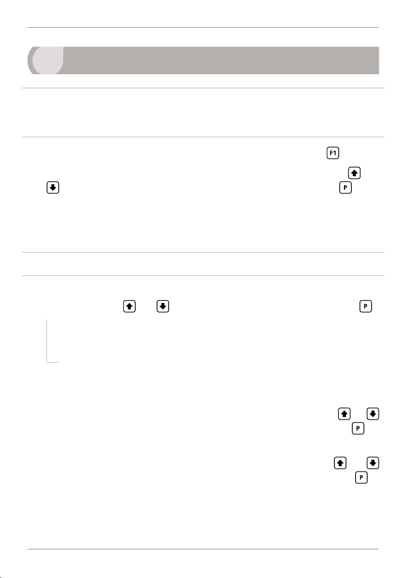
3.3 - Up and down button shortcuts
Pressing the and buttons from the main operational display allows instant
access to a number of values held in the controller's memory. These variables will appear in the order shown in the table below, and will cycle continuously at each press
of the or button. Press at any time to return to normal operating mode.
PEAK and VALLEY may be reset to zero by pressing the
and buttons at the
same time while the variable is being displayed.
Up and down button shortcuts
PEAK The maximum measured weight since the instrument was turned on or reset
RAW IP The current raw value of the input signal in mV
VALLEY The minimum measured weight since the instrument was turned on or reset
PRO-WEI100-MAN-19V01 (0225) Copyright © 2019 Dene Instruments
Page 8

8
4
WIRING
BEFORE YOU BEGIN WIRING, ensure that the unit is switched o and the power
supply is disconnected.
4.1 - Pinouts
A C
D
B
Key
4.1A Relay Output (See 4.3)
4.1B Serial Port (See 4.5)
4.1C Analog Output (See 4.4)
4.1D Analog Input (See 4.2)
4.1E Function Pins (See 4.6)
4.1F Power Supply HV/LV
E
F
(See 4.7)
4.2 - Wire the strain gauge input module
Wire your loadcell input module as shown in the diagram. This input module is pre-calibrated for 0–10,000
counts full scale with a 2.000mV/V load cell sensor.
See 4.1D
Sense
Sense
+ EXC
+ Sense
-
+ EXC
+ Sense
-
PRO-WEI100-MAN-19V01 (0225) Copyright © 2019 Dene Instruments
EXC
EXC
Input sig. high
Input sig. low
Input sig. high
Input sig. low
-
-
Guard
Not connected
Guard
Not connected
Page 9

4.3 - Wire the relay outputs (if installed)
SP2 SP1
SP3SP4 SP1SP2
+mA
If your controller has relay outputs tted, wire them as shown below. Relays can be
programmed to operate within the total span range of the controller.
See 4.1A
9
-R2
-R4
4.4 - Wire the analog output (if installed)
If your controller has analog output tted, wire it as shown for either
voltage (0–10V) or current (4–20mA).
See 4.1C
4.5 - Wire the serial port (if installed)
-S2R
If your controller has serial port tted, wire it as
shown in the applicable diagram. (S2R: RS232, RJ11
terminal, S4S: RS485, screw terminal).
N/C
SGND
+5V DC (option)
RXD
See 4.1B
TXD
N/C
-A
–V+V–mA
-S4S
D -D +
SGND
PRO-WEI100-MAN-19V01 (0225) Copyright © 2019 Dene Instruments
Page 10

10
User 1
User 2
User 3
4.6 - Wire the function pins
Connect external switches to enable a function to be
executed when its switch is activated.
Pin functions are user congurable, and can be set up
in 6.2I–K.
N/C
See 4.1E and Appendix A
COM
4.7 - Wire the power supply
DO NOT attempt to wire your controller while the power is on. NEVER connect your
low voltage controller to mains power.
Wire your controller for low or high voltage power supply, as show in the diagrams
below. Check the label on the unit against the colour of the connector:
› Orange =
High voltage (85–265V AC,
95–370V DC)
› Black =
Low voltage (15–48V AC,
10–72V DC)
See 4.1F
Once you have completed the wiring process it is safe to switch on your power
supply. Ensure that your display is functioning before you proceed.
High
voltage
(HV)
+DC
Live
AC
HV power
supply
−DC
Neutral
AC
Low
voltage
(LV)
+DC
Live
AC
LV power
supply
−DC
Neutral
AC
PRO-WEI100-MAN-19V01 (0225) Copyright © 2019 Dene Instruments
Page 11

11
120
39
155mm (6.10") minimum depth required behind panel
5
DIMENSIONS & INSTALLATION
5.1 - Case dimensions
mm (0.16")
4
96
mm
92mm
(3.78")
(3.62")
mm (4.72")
mm (1.54")
Cabling
Allowance
155mm (6.10") minimum depth required behind panel
mm
48
(1.89")
120 mm (4.72") 39mm (1.54")
mm (0.16")
4
45mm
(1.77")
Cabling
Allowance
PRO-WEI100-MAN-19V01 (0225) Copyright © 2019 Dene Instruments
Page 12

12
Panel Meter Faceplate
Panel Cutout
5.2 - Installation instructions
A Prepare the Panel Cutout to
92 x 45mm ±.5 (3.62 x 1.77" ±.02),
as shown below. Allow at least
155mm (6.10") depth behind the
panel to accommodate the meter
body and protruding cabling.
B Remove the Mounting Clips from
the meter back.
Panel
Gasket
Mounting
Clips
Screws
C Slide the Panel Gasket over the
rear of the unit to the back of the
Meter Faceplate.
D From the front of the panel, insert
the meter into the Panel Cutout.
Holding the unit in place, engage
the Mounting Clips so that the tabs
snap into place over the notches on
the case.
E To achieve a proper seal, tighten
the Screws evenly until the unit sits
rmly against the panel. Do not
over-tighten the screws.
92mm ±.5
(3.62″ ±.02)
45mm ±.5
(1.77″ ±.02)
PRO-WEI100-MAN-19V01 (0225) Copyright © 2019 Dene Instruments
Page 13
13
6
INPUT SETUP & CALIBRATION
6.1 - Enter F1 PIN number
A Enter the calibration mode by pressing the button.
_ _ _ ENTER F1 PIN scrolls across the display and toggles with 0. Use the
buttons to enter your security code (factory default 1). Then press . If the
correct PIN is entered, setup is started at 6.2.
If an incorrect PIN number is entered, _ _ _ ACCESS DENIED scrolls across the
display and it returns to normal operating mode.
You will have the opportunity to change your PIN number at the end of this section
(6.9). If you have forgotten your PIN number, see Section 9.
and
6.2 - Input setup
A _ _ _ INPUT SETUP scrolls across the display and toggles with SKIP. Press to
skip to 6.3, or the button and then to ENTER input setup.
B _ _ _ SUPPLY REJECTION FREQUENCY scrolls across the display. Use the
and buttons to select 50HZ or 60HZ, and then press .
C _ _ _ SAMPLING RATE scrolls across the display and toggles with the current
selection. Use the
1HZ, 2HZ, 5HZ, 10HZ, or 50HZ/60HZ (50 or 60Hz will depend on your selection
in 6.2B above). Then press .
D _ _ _ DECIMAL POINT POSITION scrolls across the display and toggles with the
current selection. Use the
0.00, 0.000 or 0.0000, and then press to accept and continue.
E _ _ _ ROUNDING scrolls across the display and toggles with the current display
rounding. Using the
100, 200, 500, or 1000. Then press .
and buttons to select an option from the following list:
and buttons to select NO DP (default), 0.0,
and buttons, select: NONE (default), 2, 5, 10, 20, 50,
PRO-WEI100-MAN-19V01 (0225) Copyright © 2019 Dene Instruments
Page 14

14
Rounding is quoted in display counts and is not inuenced by decimal point position. For exam-
ple, if your input signal is 5.3, the display will show: 5.3 (for rounding=NONE), 5.4 (for round-
ing=2), 5.5 (for rounding=5), 5.0 (for rounding=10), etc.
F _ _ _ MODE scrolls across the display and toggles with the current weighing
mode. Use the and buttons to select NORMAL (default) or BATCH, and
then press .
¨ If you selected NORMAL, skip to 6.2H now.
¨ If you selected BATCH, continue to 6.2G now.
In NORMAL (default) mode the controller displays the gross or net weight on the display, and
does not perform any batch calculations. In BATCH mode the controller displays batch or gross
weight, and SP 1 and SP 2 function as dedicated batch control setpoints (see 2.1).
G _ _ _ BATCHING DIRECTION scrolls across the display and toggles with current
selection. Use the and buttons to select either: LIW (loss in weight, for
emptying operations) or GIW (gain in weight, for lling operations). Press .
See Section 2.1 for additional information.
For 6.2H–K, please refer to the list of input functions in Appendix A.
H _ _ _ PROG BUTTON scrolls across the display and toggles with the current
selection. Referring to the table in Appendix A, use the
and buttons
to select a function to be performed when the button is pressed: HOLD,
TARE1, BATCH2, ZERO, PEAK, PK RST or PRINT. Then press .
I _ _ _ USER INPUT1 scrolls across the display and toggles with the current selec-
tion. This controls the function that will be performed when the User 1 input pin
at the rear of the meter (see 4.6) is activated. Referring to the table in Appendix
A, use the
and buttons to select: LOCK, TARE1, BATCH2, ZERO, PEAK,
PK RST, PRINT, GROSS, START2 or STOP2. Then press .
J _ _ _ USER INPUT2 scrolls across the display and toggles with the current selec-
tion. This controls the function that will be performed when the User 2 input pin
at the rear of the meter (see 4.6) is activated. Referring to the table in Appendix
A, use the
and buttons to select: HOLD, TARE1, BATCH2, ZERO, PEAK,
PK RST, PRINT, GROSS, START2 or STOP2. Then press .
PRO-WEI100-MAN-19V01 (0225) Copyright © 2019 Dene Instruments
Page 15

15
K _ _ _ USER INPUT3 scrolls across the display and toggles with the current selec-
tion. This controls the function that will be performed when the User 3 input pin
at the rear of the meter (see 4.6) is activated. Referring to the table in Appendix
A, use the and buttons to select: TARE1, BATCH2, ZERO, PEAK, PK RST,
PRINT, GROSS, START2 or STOP2. Then press .
L _ _ _ FLASH GROSS scrolls across the display and toggles with the currently
selected setting. Using the
This will cause the display to toggle between the Net/Gross values for 3 seconds each. Toggling
will only occur if the controller has been tared and the Net/Gross values are dierent. The NET
LED indicates which value is being displayed (On: Net, O: Gross). This option will be disabled
if a batch is currently in progress.
1
TARE feature is only available when the Mode is set to NORMAL (see 6.2F).
2
BATCH, START and STOP features are only available when the Mode is set to BATCH (see 6.2F).
and buttons, select NO or YES, and press .
6.3 - Calibration
This unit has been calibrated for 0–10,000 counts (2mV/V sensor gain at full scale).
A _ _ _ CALIBRATION TECHNIQUE scrolls across the display and toggles with
SKIP. Press
to skip to 6.4, or use the and buttons to select a calibration
method: AUTO, MV/V, ZERO, E_CAL, or CALSET, and press to continue.
¨ If you selected AUTO, complete steps 6.3B–F now.
¨ If you selected MV/V, complete steps 6.3G–I now.
¨ If you selected ZERO, complete step 6.3J now.
¨ If you selected E_CAL, complete steps 6.3K–L now.
¨ If you selected CALSET, complete steps 6.3M–N now.
¨ If you selected SKIP, skip to 6.4 now.
AUTO calibration uses zero and span values to calculate the scale and oset. This is the most
accurate calibration method, but requires known low and high input signals, usually supplied
by test weights. Zero and span calibration procedures are performed separately.
MV/V uses values from the load cell manufacturer’s test certicate.
ZERO allows manual adjustment of the calibrated zero oset.
E_CAL allows the user to view and edit the electronic calibration values (zero oset and scale
factor). These two values are updated when any calibration is performed. Noting these values
and entering them into another instrument will copy the calibration. You may also 'trim' these
PRO-WEI100-MAN-19V01 (0225) Copyright © 2019 Dene Instruments
Page 16

16
values to alter the current calibration.
CALSET allows the user to select and switch between calibration sets, giving them the option
of saving and restoring a previous calibration.
Auto calibration
B _ _ _ CAL SET X – CALIBRATE ZERO scrolls across the display, where X is the Cal
Set where the current calibration will be stored (see 6.3M). – CALIBRATE ZERO
toggles with the currently selected option. Use the
and buttons to select
YES or NO, and then press .
¨ If you selected YES, continue to 6.3C now.
¨ If you selected NO, skip to 6.3D now.
C _ _ _ REMOVE WEIGHT – PRESS P TO ACCEPT scrolls across the display and
toggles with the current no-load value. Remove the weight. Use the
and
buttons to adjust the no-load value if required, and then press .
D _ _ _ CALIBRATE SPAN scrolls across the display and toggles with the current
selection. Use the
and buttons to select YES or NO, and then press .
¨ If you selected YES, continue to 6.3E now.
¨ If you selected NO, skip to 6.3F now.
E _ _ _ ADD CAL WEIGHT – ENTER DESIRED SPAN – PRESS P TO ACCEPT scrolls
across the display and toggles with the current span value. Apply a calibration
weight to the weigh platform. Then use the
and buttons to adjust the
value, and press to accept.
F If Auto calibration was successful, you will be directed out of the calibration
menu to the operational display without viewing any further scrolling messag-
es. (To enter step 6.4, you must select SKIP at 6.3A.)
If calibration fails, _ _ _ CALIBRATION FAILED will scroll across the display and
you will be directed back to the operational display. Check your signal and con-
nections, and then repeat the calibration procedure.
PRO-WEI100-MAN-19V01 (0225) Copyright © 2019 Dene Instruments
Page 17
17
mV/V calibration
G _ _ _ ENTER TOTAL FULL SCALE WEIGHT OF LOAD CELLS IN COUNTS scrolls
across the display and toggles with the current selection. Using the
and
buttons, enter the total full scale weight of the connected load cell(s) in counts,
referring to the load cell manufacturer's test certicate. Then press .
H _ _ _ ENTER MV/V FROM LOAD CELL scrolls across the display and toggles with
the current selection. Using the
and buttons, enter the mV/V (or average
mV/V) of the connected load cell(s), and then press .
I _ _ _ SET ZERO NOW? scrolls across the display and toggles with the current
selection. Use the
Selecting YES sets your zero position when the load cells are powered up and in position.
and buttons to select YES or NO, and then press .
mV/V calibration is now complete. You will be directed back to the operational
display. (To enter step 6.4, you must select SKIP at 6.3A.)
Zero (oset) calibration
J _ _ _ ADJUST OFFSET scrolls across the display and toggles with the currently
selected zero value. Place a known weight on the weigh platform if required,
and use the
The oset will be automatically calculated to match the desired weight, and the scale factor will
not be altered. (Normally the weight would be removed and the value would be zero.)
and buttons to enter the desired value. Press to accept.
Zero calibration is now complete. You will be directed back to the operational
display. (To enter step 6.4, you must select SKIP at 6.3A.)
E_Cal calibration
K _ _ _ E_CAL ZERO OFFSET scrolls across and toggles with the current selection.
Use the
This is updated aer each calibration to show the internal ZERO OFFSET E Cal value.
and buttons to adjust the zero oset value, and then press .
L _ _ _ E_CAL SCALE FACTOR scrolls across and toggles with the current selec-
tion. Use the and buttons to adjust the scale factor value, and press .
PRO-WEI100-MAN-19V01 (0225) Copyright © 2019 Dene Instruments
Page 18

18
This is updated aer each calibration to show the internal SCALE FACTOR E Cal value.
E_Cal calibration is now complete. You will be directed back to the operational
display. (To enter step 6.4, you must select SKIP at 6.3A.)
Cal set selection
M _ _ _ SELECT CAL SET scrolls across and toggles with the current selection. Use
and buttons to choose either SET 1 or SET 2, and then press .
the
This feature allows you to save two sets of calibration values on the controller, and to roll back
to a previous calibration, if necessary. The set that you select will be the active calibration set.
N _ _ _ CALIBRATION TECHNIQUE scrolls across the display and toggles with
SKIP. You are now back at 6.3A. Press to skip to 6.4, or use the and
buttons to select a new calibration method, and then press .
6.4 - Zero maintenance
See Section 2.4 for more information on zero maintenance parameters.
A _ _ _ ZERO MAINTENANCE scrolls across the display and toggles with SKIP. Press
to skip to 6.5, or the button and then to ENTER zero maintenance.
B _ _ _ AUTO ZERO scrolls across the display and toggles with the current auto
zero selection. Use the
and buttons to select ON or OFF, and press .
¨ If you selected ON, continue to 6.4C now.
¨ If you selected OFF, skip to 6.4E now.
If AUTO ZERO mode is ON, the controller’s oset will be automatically adjusted so that the
instrument reads zero when it senses that the scale is not loaded (see 2.4).
C _ _ _ CAPTURE BAND scrolls across the display and toggles with the selected
capture band. Adjust this value using the and buttons, and then press .
This is referenced to the current zero value, and is the maximum number of display counts that
the controller will zero within. CAPTURE BAND can be set from 1 to 254 counts, and should
always be set to less than the smallest weight to be measured.
PRO-WEI100-MAN-19V01 (0225) Copyright © 2019 Dene Instruments
Page 19

19
Input signal in counts
Sampling
D _ _ _ MOTION BAND scrolls across the display and toggles with the selected
motion band. Adjust this value using the and buttons, and then press .
This provides a rate of change limit setting, to determine the number of counts/second allowed
within the CAPTURE BAND. MOTION BAND can be set from 0 to 255 counts. Typical value is
1 or 2 counts/sec.
E _ _ _ ZERO BAND scrolls across the display and toggles with the selected zero
band. Adjust this value using the and buttons, and then press .
This provides a limit for the number of counts of zero oset allowed to accumulate, relative to
the calibrated zero setting. If the accumulated zero oset becomes greater than this window,
then the controller displays the current loadcell value and does not zero. The suggested limit
for the ZERO BAND is 2% of the calibrated span.
6.5 - Averaging
Your controller has input signal averaging, optimising stable measurement.
If the change in input exceeds the
averaging window value it will not
average, ensuring fast response when
there are large dierences between
readings. (E.g. When product is being
dropped into a bag.)
Input exceeds
averaging window
Number
of samples
Averaging window
in displayed counts
A _ _ _ AVERAGING PARAMETERS scrolls across and toggles with SKIP. Press
to skip to 6.6, or the button and then to ENTER averaging setup.
B _ _ _ AVE SAMPLES scrolls across the display and toggles with the currently
selected averaging. Using the
and buttons, alter the number of input
samples that the controller will average, and then press .
Increasing the number of samples will stabilise measurement, but it will also slow down response rates. A typical value is 4.
C _ _ _ AVE WINDOW scrolls across the display and toggles with the currently
selected averaging window value. Using the and buttons, alter the signal
averaging window. Then press .
If your input signal contains large noise spikes, you can increase the size of the averaging window to ensure that these are still averaged. However, increasing the window size too far will
PRO-WEI100-MAN-19V01 (0225) Copyright © 2019 Dene Instruments
Page 20

20
reduce the ability of the controller to respond quickly to real changes in input signal. Setting
AVE WINDOW to 0 will give continuous averaging as per the selected averaging samples. A
typical value is 10% of your system capacity.
6.6 - Analog output setup
N.B. All new units are calibrated before shipping. Recalibration is only necessary if settings
are wiped or the unit's accuracy requires verication aer a long period of use. e.g. 1 year.
A _ _ _ ANALOG OUTPUT SETUP scrolls across the display and toggles with SKIP.
If your controller does not have analog output installed, (or you do not wish to
congure your analog output now), press to skip to 6.7.
Otherwise, press the
button and then to ENTER analog output setup.
B _ _ _ DATA SOURCE FOR ANALOG O/P scrolls across the display and toggles
with the current analog output data source. Use the
and buttons to
select an option from: NET/BATCH, or LIVE, and then press .
Note that where NET/BATCH is indicated, the option that will be displayed is controlled by the
weighing mode selected in 6.2F. NORMAL mode = NET, BATCH mode = BATCH.
C _ _ _ LOW SCALE VALUE FOR ANALOG O/P scrolls across the display and tog-
gles with the currently selected low scale display value. Use the and buttons to enter your cal low position, and then press .
D _ _ _ HIGH SCALE VALUE FOR ANALOG O/P scrolls across the display and
toggles with the currently selected high scale display value. Use the
and
buttons to enter your cal high position, and then press .
To calibrate your analog output, see Section 10.
Factory analog output calibration is precisely set before shipping this instrument,
and should not be adjusted unless advised by the manufacturer.
6.7 - Serial setup
A _ _ _ SERIAL SETUP scrolls across the display and toggles with SKIP. If your
controller does not have a serial port installed, (or you do not wish to congure
your serial options now), please press to skip to 6.8.
PRO-WEI100-MAN-19V01 (0225) Copyright © 2019 Dene Instruments
Page 21
21
Otherwise, press the button and then to ENTER serial setup.
B _ _ _ SERIAL MODE scrolls across the display and toggles with the current serial
mode. Use the
and buttons to choose between: ASCII (custom), MOD-
BUS (RTU), GEDGE, RNGR A (Ranger A), or PRINT. Then press .
¨ If you selected GEDGE, continue to 6.7C now.
¨ If you selected RNGR A or PRINT, skip to 6.7D now.
¨ If you selected ASCII or MODBUS, skip to 6.7H now.
See Appendix B for more information about the available serial modes.
C _ _ _ OUTPUT FORMAT scrolls across the display and toggles with the currently
selected Gedge output format. Use the and buttons to choose between
C1, C2, or C3, and then press .
¨ Please skip to 6.7G now.
See Appendix B.3 for more information on Gedge output formats.
D _ _ _ DATA SOURCE scrolls across the display and toggles with the currently
selected serial data source. Use the and buttons to select an option from:
NET/BATCH, LIVE, or PEAK, and then press .
Note that where NET/BATCH is indicated, the option that will be displayed is controlled by the
weighing mode selected in 6.2F. NORMAL mode = NET, BATCH mode = BATCH.
E The step that you proceed to now will depend on the Serial Mode that you
selected in 6.7B:
¨ If your Serial Mode = PRINT, continue to 6.7F now.
¨ If your Serial Mode = RNGR A, skip to 6.7G now.
F _ _ _ PRINT UNITS scrolls across the display and toggles with the current units
that will be printed on the Weigh Ticket (see B.5) when the print function is trig-
gered. Use the
and buttons to choose between NONE, GRAMS, KGS,
TONNES, LBS or KN, and then press .
¨ Please skip to 6.7H now.
PRO-WEI100-MAN-19V01 (0225) Copyright © 2019 Dene Instruments
Page 22

22
This option controls the units that are printed on the Weigh Ticket (see B.5). It does not perform any conversion calculations. Please scale the instrument to match the printed units.
G _ _ _ OUTPUT MODE scrolls across the display and toggles with the current
output mode. Use the and buttons to select either CONT (continuous) or
PULSED, and then press .
In CONT (continuous) mode, the controller outputs a continuous stream of data. In PULSED
mode, the controller outputs a single string when the print function is triggered from a user
input button or pin (see 6.2H–K and Appendix A).
H _ _ _ BAUD RATE scrolls across the display and toggles with the current selec-
tion. Use the and buttons to select one of: 300, 600, 1200, 2400, 4800,
9600, 19200 or 38400. Then press .
I _ _ _ PARITY scrolls across the display and toggles with the currently selected
parity. Using the
and buttons, select: NONE, ODD or EVEN, and then
press .
J The step that you proceed to now will depend on the Serial Mode that you
selected in 6.7B:
¨ If your Serial Mode = GEDGE, RNGR A, or PRINT, continue to 6.7K now.
¨ If your Serial Mode = ASCII or MODBUS, skip to 6.7L now.
K _ _ _ DATA BITS scrolls across the display and toggles with the currently selected
data bits. Using the
and buttons, select: 7 or 8, and then press .
¨ The last step only applies to ASCII or MODBUS mode. Proceed to 6.8 now.
L _ _ _ SERIAL ADDRESS scrolls across the display and toggles with the currently
selected serial address. Use the
and buttons to alter the serial address,
and then press .
The serial address parameter is used to identify a particular device when it is used with other
devices in a system. (It applies particularly to MODBUS mode when used on an RS485 serial
network.) The serial address of the controller must be set to match the serial address dened
in the master device.
PRO-WEI100-MAN-19V01 (0225) Copyright © 2019 Dene Instruments
Page 23

23
Refer to Appendix B for more information on serial modes and registers.
6.8 - Clock setup
A _ _ _ CLOCK SETUP scrolls across the display and toggles with SKIP. Press to
skip to 6.9, or the button and then to ENTER and set the date and time.
B _ _ _ HOURS scrolls across the display and toggles with the current selection.
Use the
The controller's internal clock uses 24 hour time; you cannot select a.m. or p.m.
C _ _ _ MINUTES scrolls across the display and toggles with the current selection.
Use the and buttons to adjust the minutes (from 0 to 59), and press .
Aer pressing the seconds timer will be reset to zero, and will immediately begin counting.
D _ _ _ DATE scrolls across the display and toggles with the current selection. Use
the and buttons to adjust the date (from 1 to 31), and press .
E _ _ _ MONTH scrolls across the display and toggles with the current selection.
Use the
and buttons to adjust the hour (from 0 to 23), and press .
and buttons to select a month (from JAN to DEC), and press .
F _ _ _ YEAR scrolls across the display and toggles with the current selection. Use
and buttons to adjust the display to the current year, and press .
the
6.9 - Edit F1 PIN number
A _ _ _ EDIT F1 PIN scrolls across the display and toggles with SKIP. Press to
skip and return to the operational display, or the button and then to
ENTER and change your PIN number.
B _ _ _ ENTER NEW F1 PIN scrolls across the display and toggles with the current
PIN (default 1). Using the
Then press to exit to the operational display.
and buttons, enter your new F1 PIN number.
PRO-WEI100-MAN-19V01 (0225) Copyright © 2019 Dene Instruments
Page 24

24
7
The soware in your controller will allow you to congure up to 4 setpoints,
however full functionality is only supported when relay output hardware installed.
(Setpoints with no corresponding relay output hardware may be used as simple LED
indicators, if desired. In this case, features requiring relay output functionality will
continue to appear in the setup menu, but will be ignored by the controller.)
SETPOINT SETUP
7.1 - Enter F2 PIN number
A Enter setpoint setup mode by pressing and holding the button for 3 seconds.
_ _ _ ENTER F2 PIN scrolls across the display and toggles with 0. Use the
buttons to enter your security code (factory default 1). Then press . If the
correct PIN is entered, setup is started at 7.2.
If an incorrect PIN number is entered, _ _ _ ACCESS DENIED scrolls across the
display and it returns to normal operating mode.
You will have the opportunity to change your PIN number at the end of this section
(7.3). If you have forgotten your PIN number, see Section 9.
and
7.2 - Setpoint setup
A _ _ _ EDIT SETPOINT scrolls across the display and toggles with SKIP. Press
now to skip to 7.3, or use the and buttons to select a setpoint to edit,
and then press .
B _ _ _ SP VALUE scrolls across the display and toggles with the current value for
the selected setpoint. Using the
which the selected setpoint will activate, and then press .
C The step that you proceed to now will depend on which setpoint you are editing
(selected in 7.2A):
PRO-WEI100-MAN-19V01 (0225) Copyright © 2019 Dene Instruments
and buttons, adjust the display value at
Page 25

25
¨ If you are currently editing SP 1, skip to 7.2E now.
¨ If you are currently editing SP 2–4, continue to 7.2D now.
D _ _ _ TRAIL SP1 scrolls across the display and toggles with the tracking setting
for the selected setpoint. Using the
and buttons, select OFF or ON, and
then press .
A setpoint with TRAIL SP1 enabled will track the setpoint value of SP 1, with the setpoint value
of the tracking setpoint becoming an oset value.
E The step that you proceed to now will depend on which setpoint you are editing
(selected in 7.2A):
¨ If you are currently editing SP1–2, then the step that you proceed to now
will depend on your controller's weighing mode (selected in 6.2F):
` If your controller is in NORMAL mode, continue to 7.2F now.
` If your controller is in BATCH mode, skip to 7.2J now.
¨ If you are currently editing SP 3–4, continue to 7.2F now.
F _ _ _ SP SOURCE scrolls across the display and toggles with the activation source
for the selected setpoint. Use the
and buttons to choose NET/BATCH or
LIVE, and then press .
Note that where NET/BATCH is indicated, the option that will be displayed is controlled by the
weighing mode selected in 6.2F. NORMAL mode = NET, BATCH mode = BATCH.
G _ _ _ SP ACTIVATION scrolls across the display and toggles with the current ac-
tivation for the selected setpoint. Using the and buttons, select the relay
activation to operate ABOVE or BELOW the setpoint value, and then press .
ABOVE: Relay turns on above the setpoint value and o below it. BELOW: Relay turns on be-
low the setpoint value and o above it.
H _ _ _ HYSTERESIS VALUE scrolls across the display and toggles with the hyster-
esis value for the selected setpoint. Use the and buttons to adjust this
value if required, and then press .
¨ If you set the Hysteresis Value to 0, skip to 7.2J now.
¨ If you set the Hysteresis Value to anything else, continue to 7.2I now.
The HYSTERESIS VALUE denes the separation band between setpoint activation and deacti-
vation, and will operate as per the HYSTERESIS TYPE setting selected in 7.2I.
PRO-WEI100-MAN-19V01 (0225) Copyright © 2019 Dene Instruments
Page 26

26
Energised Above
Energised Above
I _ _ _ HYSTERESIS TYPE scrolls across the display and toggles with the hyster-
esis type for the selected setpoint. Using the and buttons, select either
ALARM or CNTRL (control), and then press .
ALARM - SETPOINT VALUE controls setpoint
activation point. HYSTERESIS VALUE con-
trols setpoint deactivation point.
CNTRL - SETPOINT VALUE controls setpoint
deactivation point. HYSTERESIS VALUE con-
trols setpoint reactivation point.
Hysteresis
band
Hysteresis
band
Energised Below
Hysteresis
band
Hysteresis
band
Energised Below
J _ _ _ MAKE DELAY scrolls across the display and toggles with the current make
delay time for the selected setpoint. This is the time delay between setpoint activation, and when the relay turns on. Adjust this value in 0.1 second increments
using the and buttons, and then press .
K _ _ _ USER ACCESS? scrolls across the display and toggles with the direct access
permission setting for the selected setpoint. Use the
and to select either
OFF or ON, and then press .
When enabled, this option allows the selected setpoint's value to be edited directly aer pressing the button, without needing to enter a PIN number or go through all of the other options. Each setpoint can individually have this option enabled or disabled. See Section 8.
L _ _ _ EDIT SETPOINT scrolls across the display and toggles with SKIP. You are
now back at 7.2A. To edit another setpoint, follow the instructions from 7.2A–L
again. If you do not wish to edit another setpoint, press now to skip to 7.3.
7.3 - Edit F2 PIN number
A _ _ _ EDIT F2 PIN scrolls across the display and toggles with SKIP. Press to
skip and return to the operational display, or the button and then to
ENTER and change your PIN number.
B _ _ _ ENTER NEW F2 PIN scrolls across the display and toggles with the current
PIN (default 1). Using the
and buttons, enter your new F2 PIN number.
Then press to exit to the operational display.
PRO-WEI100-MAN-19V01 (0225) Copyright © 2019 Dene Instruments
Page 27
27
8
If none of the setpoints have their direct access option enabled then this feature will
be disabled and the
A Begin by pressing the
B The name of the rst access-enabled setpoint will appear on the display and
toggle with the current value for that setpoint. Using the
adjust the selected value. Then press to accept and continue.
C The name of the next access-enabled setpoint will appear on the display, along
with its setpoint value. Repeat step 8B. The direct access menu will proceed
through all access-enabled setpoints in this fashion. Pressing
bled setpoint will exit and return to the operational display.
9
If you have forgotten your PIN number(s), follow the procedure below to reset both
the F1 and F2 PINs to their factory default of 1.
This procedure will also allow you to view the current soware installed on your
controller, which may be required for support purposes.
SETPOINT DIRECT ACCESS
button will not respond to a short button press. (See 7.2K.)
button for less than 3 seconds.
and buttons,
for the last ena-
RESET PIN NUMBERS / VIEW FIRMWARE VERSION
A Press
execute and you may need several tries to get it right.)
B A message will appear on the display, with details of the unit's current soware
conguration (Product Name, Firmware Version, and Macro Version). At the
end, you will see PIN RESET TO 1.
C Both the F1 PIN number and the F2 PIN number have now been reset to '1'.
You can change this, if required, by following the instructions in 6.9 (for the F1
menu) and 7.3 (for the F2 menu), using '1' to enter each menu initially.
, and at the same time. (This key combination can be dicult to
PRO-WEI100-MAN-19V01 (0225) Copyright © 2019 Dene Instruments
Page 28
28
10
Do not access this feature unless instructed by the manufacturer.
Factory analog output calibration is precisely set before shipping this instrument. For
analog output scaling, see 6.6.
A Start with the controller powered o. Power up while holding the
B _ _ _ ENTER F1 PIN scrolls across the display and toggles with 0. Use the
correct PIN is entered, continue to 10C.
If an incorrect PIN number is entered, _ _ _ ACCESS DENIED scrolls across the
display and it returns to normal operating mode.
If you have forgotten your PIN number, see Section 9.
C _ _ _ CALIBRATE ANALOG O/P? scrolls across and toggles with the current
selection. Use the
N.B. All new units are calibrated before shipping. Recalibration is only necessary if settings
are wiped or the unit's accuracy requires verication aer a long period of use. e.g. 1 year.
FACTORY ANALOG OUTPUT CALIBRATION
button.
and
buttons to enter your security code (factory default 1). Then press . If the
and buttons to select YES or NO, and then press .
¨ If you selected YES, connect a mA or volt meter across the analog output
connector (see 4.4), and then continue to 10D.
¨ If you selected NO, the display will return to normal operating mode.
D _ _ _ CAL LOW ANALOG O/P scrolls across the display and toggles with a cali-
bration number shown in internal units (around -16000). Press the or
buttons until the multimeter displays your target low output, then press .
E _ _ _ CAL HIGH ANALOG OUTPUT scrolls across the display and toggles with a
calibration number shown in internal units (around 30000). Press the
buttons until the multimeter displays your target high output, then press .
F Factory analog output calibration is now complete. The display will return to
normal operating mode.
PRO-WEI100-MAN-19V01 (0225) Copyright © 2019 Dene Instruments
and
Page 29

29
A
A number of user programmable functions are accessible from the
APPENDIX A - INPUT FUNCTIONS
button and
rear pins (see 6.2H–K). Note that availability of the TARE/BATCH and STAR T/STOP
features are subject to your weighing mode, as selected in 6.2F.
User programmable input functions
Function Btn/Pin & Activation
Time
HOLD
LOCK
TARE
(see 2.3)
BATCH
(see 2.1)
ZERO
(see 2.4)
Continuous
Continuous
½ sec
2+ sec
½ sec
2+ sec
½ sec
2+ sec
Description
Freezes the display value.
Locks the control panel.
Tares display value (ashes TARE).
Resets tare to zero (ashes TR RST and then shows gross).
If no batch operation is active:
Performs a batch operation; display shows BATCH
If a batch operation is in progress:
Current batch is paused; display shows PAUSE
If a batch operation has been paused, or you have just
powered up following a power loss during batching:
Controller will resume without resetting the batch
value; display shows RESUME
Resets the batch value to zero and ashes BT RST. Any
current batching operations will be halted.
Zeroes the weight if the zero oset (i.e. the dierence between the current no load weight and the calibration no
load value) is within the ZERO BAND (see 2.4).
If the oset is less than the limit set in ZERO BAND (see 6.4E),
the zero value is updated and the display ashes ZERO. If the
oset is greater than the limit set in ZERO BAND, the zero
value is not updated and the display scrolls OUTSIDE OF ZERO
BAND!
Resets the zero oset value to the original calibration oset value. Display ashes RS ZER and then shows gross.
PRO-WEI100-MAN-19V01 (0225) Copyright © 2019 Dene Instruments
Page 30

30
User programmable input functions
Function Btn/Pin & Activation
Time
PEAK
PK RST
PRINT
(see B.5)
GROSS Continuous
START
STOP
½ sec
2+ sec
Continuous
Continuous
Continuous
½ sec
½ sec
2+ sec
Description
Displays the peak value for 2 seconds.
Sets the peak value to the current input value (ashes PK
RST).
Displays the peak value continuously.
Sets the peak value to the current input value (ashes PK
RST).
Sends a single Ranger A output string.
SERIAL MODE (6.7B) must be set to RNGR A, and OUTPUT
MODE (6.7G) must be set to PULSED.
Displays the gross value continuously.
Starts a new batch, or resumes the batching process aer
it has been paused.
Pauses the batching process and holds the current batched
weight on the display.
Resets the batch value to zero and halts any current batching operations.
PRO-WEI100-MAN-19V01 (0225) Copyright © 2019 Dene Instruments
Page 31

31
B
APPENDIX B - SERIAL MODES
B.1 - Custom ASCII mode
Custom ASCII is a simple, custom protocol that allows connection to various PC conguration tools. ('Custom ASCII' diers from the 'Modbus (ASCII)' protocol used by
some devices.) Custom ASCII command strings must be constructed in this order:
<Start> <Controller Address> <Read/Write Command> <Register Address>
<Separator Character> <Data Value> <Message Terminator>
Start - Use 'S' for the start character of a command string (not case sensitive). This
must be the rst character in the string.
Controller Address - Use an ASCII number from '1' to '255' for the controller address.
If the character following the start character is not an ASCII number, then address '0' is assumed. All controllers respond to address '0'.
Read/Write Command - Use ASCII 'R' for read, 'U' for unformatted read, or 'W' for
write (not case sensitive). Any other character aborts the operation.
In Custom ASCII mode, data is normally read as formatted data (which includes decimals and
any text characters that may be selected to show units). However it is also possible to read unformatted data by using a 'U' in the read command. There is no unformatted write command,
as when writing to xed point registers, any decimal point and text characters are ignored.
Register Address - The register address for the read/write operation will be an ASCII
number from '1' to '65535'. This character must be specied for a write command, but may be omitted for a read command, (in which case the controller
will respond with the data value currently on the display).
Separator Character - The separator character can be either a space or a comma,
and is used to separate the register address from the data value.
Data Value - Must be an ASCII number. The absolute limits for this number are
–
1000000 to +1000000, but note that not all registers will accept this range.
Message Terminator - This is the last character, and must be either a '$' (dollar) or
an '*' (asterisk). Neither of these characters should be used elsewhere in the
PRO-WEI100-MAN-19V01 (0225) Copyright © 2019 Dene Instruments
Page 32

32
message string. If '$' is used, a 50ms minimum delay is inserted before a reply is
sent. If '*' is used, a 2ms minimum delay is inserted before a reply is sent.
Custom ASCII Read/Write Examples
Example Description
SR$ Read display value from all controllers, 50ms delay.
S15R$ Read display value from controller address 15, 50ms delay.
S3U40* Read unformatted data in channel 4 from controller address 3, 2ms delay.
–
S2W2 –10000$ Write
SWT CHAN_1$ Write ASCII text string Chan_1 to channel 1 text register, 50ms delay.
10000 to the display register of controller address 2, 50ms delay.
Controller Response - Aer the controller has completed a read or write instruction,
it responds by sending a carriage return/line feed (CR/LF) back to the host. If
the instruction was a read command, the CR/LF follows the last character in the
ASCII string. If it was a write command, CR/LF is the only response sent back.
The host must wait for this before sending further commands to the controller.
If the controller encounters an error, it will respond with a null (0x00) CR/LF.
Custom ASCII Registers
16 Bit Unsigned
Address Function
1 Alarm status (SP1=Bit 0, SP2=Bit
1, SP3=Bit 2, SP4=Bit 3)
65–68 Hysteresis (SP1=65, SP2=66, SP3
=67, SP4=68)
71–74 Make delay (SP1=71, SP2=72, SP
3=73, SP4=74)
PRO-WEI100-MAN-19V01 (0225) Copyright © 2019 Dene Instruments
32 Bit Signed
Address Function
3 Tared/Batch weight (net)
4 mV
39 Live weight (gross)
16 Tare value
12 Peak
13 Valley
6–9 Setpoint 1–4 (SP1=6, SP2=7, SP3
=8, SP4=9)
34 D/A scale low value
36 D/A scale high value
Page 33

33
B.2 - Modbus (RTU) mode
Modbus (RTU) is an industry standard RTU slave mode that allows connection to a
wide range of devices. Modbus registers are all holding registers, and should be accessed via function codes 3 and 6.
Register addresses are displayed in the Modicon™ 5-digit addressing format. I.e.
Register 65=40065 (subtract 1 for direct addressing).
Modbus (RTU) Registers
16 Bit Unsigned
Address Function
40001 Alarm status (SP1=Bit 0, SP2=Bit
1, SP3=Bit 2, SP4=Bit 3)
40065–
40068
40071–
40074
Hysteresis (SP1=40065, SP2=
40066, SP3=40067, SP4=40068)
Make delay (SP1=40071, SP2=
40072, SP3=40073, SP4=40074)
32 Bit Signed (2 x 16 Bit)
LSW MSW Function
40515 40516 Tared/Batch weight (net)
40517 40518 mV
40521 40522 Live weight (gross)
40529 40530 Tare value
40525 40526 Peak
40527 40528 Valley
40535
–541
40587 40588 D/A scale low value
40591 40592 D/A scale high value
40536
–542
Setpoint 1–4
(SP1=40535, SP2=40537,
SP3=40539, SP4=40541)
B.3 - Gedge mode
This serial mode is used to drive Gedge displays. Depending on your output format
selected in 6.7C, the Gedge output string will be constructed as shown:
› C1= <STX> <Displayed Weight> <ETX>
› C2= <STX> <Displayed Weight> <D2> <D3> <D4> <D5> <D6> <D7> <ETX>
› C3= <STX> <Gross Weight> <Tare Weight> < Net Weight> <D2> <D3> <D4>
<D5> <D6> <D7> <ETX>
PRO-WEI100-MAN-19V01 (0225) Copyright © 2019 Dene Instruments
Page 34

34
Gedge Command Strings
STX Start of transmission ( $02 )
ETX End of transmission ( $03 )
CR/LF Carriage return and Line feed ( $0D $0A )
Weight 8 ASCII alpha/numerics:
<Space or minus sign> <Space> <6 digits> (E.g. "– 002387") or
<Space or minus sign> <6 digits and decimal> (E.g. "–002.387")
D2 Displayed weight identity. G: Gross. N: Net. T: Tare.
D3 M: Scale is in motion. S: Scale is still.
D4 I: In scale. O: Over scale. U: Under scale.
D5 Z: Gross is zero. ASCII Space: Gross is not zero.
D6 E: Stored tare is not zero. ASCII Space: Stored tare is zero.
D7 P: Print key operation. ASCII Space: No print key operation.
B.4 - Ranger A mode
Ranger A is a continuous output, used to drive remote displays and other instruments in the Rinstrum™ range. (Ranger is a trade name belonging to Rinstrum Pty
Ltd.) Ranger A output strings are constructed as shown:
<Start> <Sign> <Output Value> <Status> <End>
Start - STX character (ASCII 02)
Sign - Output value sign (space for + and dash for -)
Output Value - Seven character ASCII string containing the current output value and
decimal point. (If there is no decimal point, then the rst character is a space.
Leading zero blanking applies.)
Status - Single character output value status. 'U'=Under, 'O'=Over, 'E'=Error.
End - ETX character (ASCII 03)
PRO-WEI100-MAN-19V01 (0225) Copyright © 2019 Dene Instruments
Page 35
35
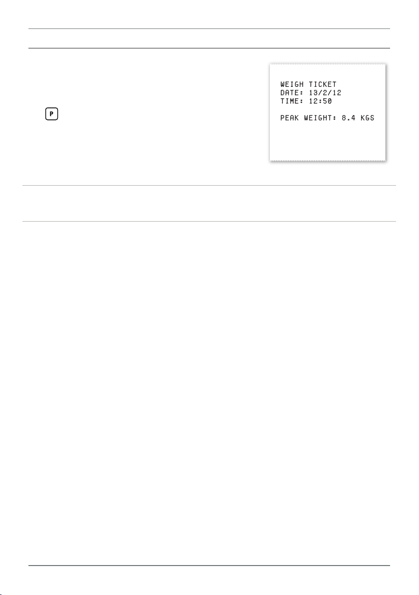
B.5 - Print mode
This mode outputs a Weigh Ticket (as shown) to the
serial port when the Print function is triggered from
the button or rear input pins (see 6.2H–K).
The weigh ticket shows the current value of the selected Serial Data Source (as set in 6.7D), and the
units selected in 6.7F.
Note that changing the display units in 6.7F does not perform any conversion
calculations. You will need to scale the instrument to match the printed units.
A date and time will also be printed on the Weigh Ticket. In order to print the cur-
rent date and time, Real-Time Clock hardware must be installed. If the required
hardware is not installed, the controller time stamp will revert back to the rmware
revision date and time whenever the unit is restarted.
PRO-WEI100-MAN-19V01 (0225) Copyright © 2019 Dene Instruments
Page 36

De ne Instruments
New Zealand
(Head O ce)
Auckland 0632, New Zealand
Auckland 0661, New Zealand
Ph
Fax
www.de neinstruments.com
10B Vega Place, Rosedale,
PO Box 245 Westpark Village,
: +64 (9) 835 1550
: +64 (9) 835 1250
sales@de neinstruments.co.nz
PRO-WEI100 MV5.3 Revision Code: PRO-WEI100-MAN-15V13 Date Code: 150826
United States (Dallas, TX)
Ph: (214) 926 4950
sales@de neinstruments.com
www.de neinstruments.com
 Loading...