

Page 1
1
PRO-PRC
Quad Process Controller
This quad channel process controller is ideal for numerous industrial applications
with 0–20mA or 4–20mA DC inputs. It can be used either on its own, or inconjunc-
tion with another instrument (such as a transmitter).
One of the key features of this controller is its ability to average the inputs across 2,
3 or 4 input channels, and use this averaged value for a display source or for setpoint
activation.
Contents
1 - Specications .............................. 2
2 - Front Panel & Display ................. 3
3 - Wiring .......................................... 5
4 - Dimensions & Installation .......... 8
5 - Input Setup & Calibration ........ 10
6 - Setpoint Setup .......................... 18
7 - Setpoint Direct Access .............. 21
8 - Reset PIN Numbers / View
Firmware Version ...................... 21
A - Appendix A - Serial Modes ....... 22
Order Codes
PRO-PRC
-HV
85–265V AC / 95–370V DC
-LV
15–48V AC / 10–72V DC
Options
-R2
2 x relay outputs
-R4
4 x relay outputs
-A 1 x mA/V analog output
-S2R 1 x RS232 (RJ11 terminal)
-S4S 1 x RS485 (screw terminal)
PRO-PRC-MAN-17V01 (0802) Copyright © 2017 Dene Instruments
Page 2

2
1
SPECIFICATIONS
Input
Input signal 4 x 0–20mA / 4–20mA
Power supply
HV (85–265V AC/95–370V DC) OR
LV (15–48V AC/10–72V DC)
Excitation 24V DC (50mA max)
Sampling rate 5Hz per channel
Resolution 100,000 counts
Zero dri 0.05μA/°C typical
Span dri ±25ppm/°C typical
Non-linearity ±0.01% full scale max
Input noise 0.3μAp-p typical (at 1Hz
output rate)
Noise rejection 50/60Hz
Relay Output
Number of relay outputs None, 2, or 4
Relay output type 5A form A (3A 240V
AC max or 3A 30V DC max)
OPTIONAL
Comm Port
Number of serial ports None or 1
Serial port options Isolated RS232 (RJ
terminal) or RS485 (screw terminal)
Output mode Custom ASCII, Modbus
RTU slave, or Ranger A
Data rate: 1200–115k2 baud
Parity: Odd, even or none
OPTIONAL
Programming
Front panel buttons Up, Down, P (Prog/
Enter), plus 2 Menu buttons (F)
Security Input and setpoint setups
are independently accessible and PIN
protected
Display
Display type LED display, 5 buttons
LED indicators 6 setpoint indicator LED's
Digits 1 row of 6 digits, 13mm (0.5"), 14
segment alphanumeric LED
Analog Output
Analog output type 1 x Isolated 16 bit
4–20mA / 0–10V (selectable)
PRO-PRC-MAN-17V01 (0802) Copyright © 2017 Dene Instruments
OPTIONAL
Display range 0.1 to 99999.9
Page 3
3
Construction
Casing Panel mount case
Ingress protection rating IP65 dust/
Dimensions (H x W x D)
48 x 96 x 120mm (1.89 x 3.78 x 4.72")
Panel cutout 45 x 92mm (1.77 x 3.62")
splash proof (face only)
2
FRONT PANEL & DISPLAY
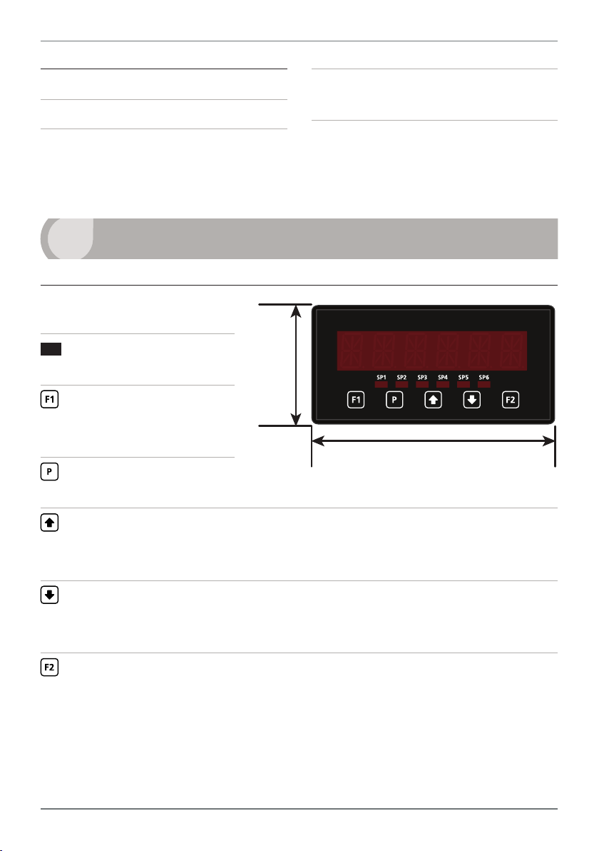
2.1 - Front panel
SPX
The SP LED's are used to
indicate active setpoints.
This button is used to ac-
cess the Input Setup & Calibra-
tion menu (Section 5).
This button is used to save
your settings and advance to the next step in the setup process.
48mm
(1.89")
96mm (3.78")
This button is typically used to scroll through options or increase values in the
setup menu. Pressing this button from the main display will allow you to view/reset
the Peak value
This button is typically used to scroll through options or decrease values in the
, or to view the current input values for channels 1–4 (see 2.3).
setup menu. Pressing this button from the main display will allow you to view/reset
the Valley value, or to view the current channel average value (see 2.3).
This button is used to access the Setpoint Setup menu (Section 6) and the Set-
point Direct Access menu (Section 7).
PRO-PRC-MAN-17V01 (0802) Copyright © 2017 Dene Instruments
Page 4
4
2.2 - Display brightness
To adjust the display brightness, press the and buttons together from the
main display. BRI appears and toggles with the current setting. Use the and
buttons to adjust the LED backlight, and then press to nish.
2.3 - Up and down button shortcuts
Pressing the and buttons from the main operational display allows instant
access to a number of values held in the controller's memory. These variables will ap-
pear in the order shown in the table below, and will cycle continuously at each press
of the or button.
Press
at any time to return to normal operating mode. PEAK and VALLEY may be
reset to zero by pressing the and buttons at the same time while the variable
is being displayed.
Up and down button shortcuts
PEAK The maximum measured value since the instrument was turned on or reset
(see 5.3H to set the source for 'Peak/Valley')
CH 1 Current input value for channel 1
CH 2 Current input value for channel 2
CH 3 Current input value for channel 3
CH 4 Current input value for channel 4
VALLEY The minimum measured value since the instrument was turned on or reset
(see 5.3H to set the source for 'Peak/Valley')
CH AVE Channel average value (see 5.3I)
PRO-PRC-MAN-17V01 (0802) Copyright © 2017 Dene Instruments
Page 5
5
+24V EXC
CH3CH2CH1 CH4
SP2 SP1
SP3SP4 SP1SP2
3
WIRING
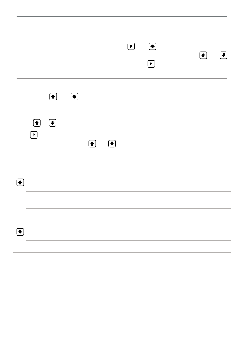
3.1 - Pinouts
A B C
D E F
Key
3.1A Relay Output (see 3.3)
3.1B Serial Port (see 3.5)
3.1C Analog Output (see 3.4)
3.1D Analog Input (see 3.2)
3.1E Function Pins (see 3.6)
3.1F Power Supply HV/LV
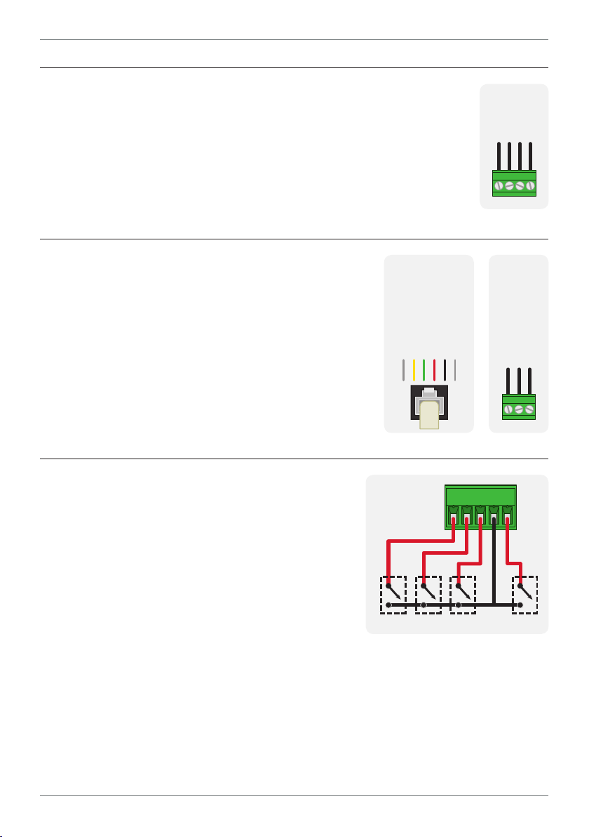
3.2 - Analog input
See 3.1D
Wire the analog input module as shown, referring to the
product label. The unit accepts up to four process inputs.
Note that you must start wiring from channel 1. (I.e. For 2 channels,
use CH1–2, not CH3–4).
(see 3.7)
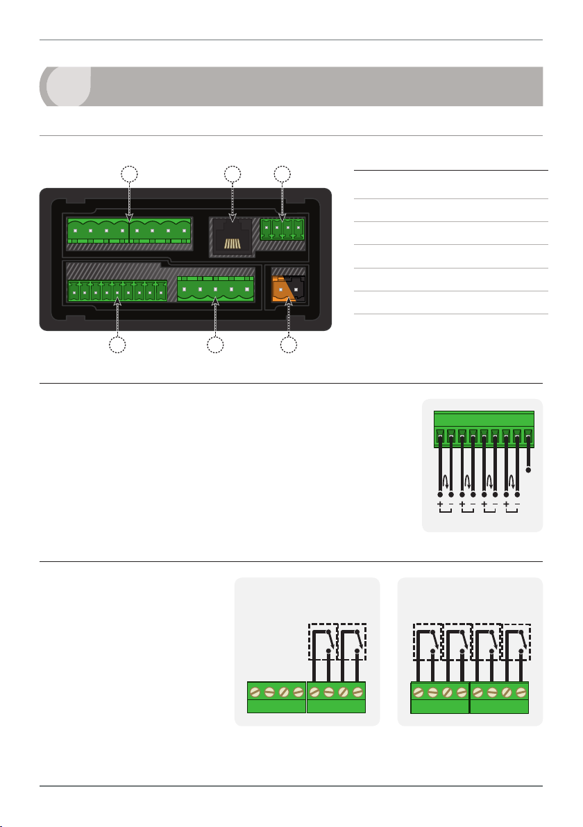
3.3 - Relay outputs
See 3.1A
If your controller has relay
outputs tted, wire them as
shown. Relays can be pro-
grammed to operate within
the total span range of the
controller.
–R2
–R4
PRO-PRC-MAN-17V01 (0802) Copyright © 2017 Dene Instruments
Page 6
6
+mA
Valley Tes tHold
Peak
3.4 - Analog output
See 3.1C
If your controller has analog output tted, wire it as shown for either
voltage (0–10V) or current (4–20mA).
3.5 - Serial port
N/C
-S2R
SGND
+5V DC (option)
RXD
See 3.1B
If your controller has serial port tted, wire it as shown
in the applicable diagram. (S2R: RS232, RJ11 terminal,
S4S: RS485, screw terminal).
3.6 - Function pins
See 3.1E
TXD
N/C
-A
–V+V–mA
-S4S
D -D +
SGND
Connect external switches as shown to enable
a function to be executed when its switch is
activated.
› Valley Resets the valley reading
› Hold Holds the current display value
› Tes t Resets the meter
› Peak Resets the peak reading
PRO-PRC-MAN-17V01 (0802) Copyright © 2017 Dene Instruments
COM
Page 7
7
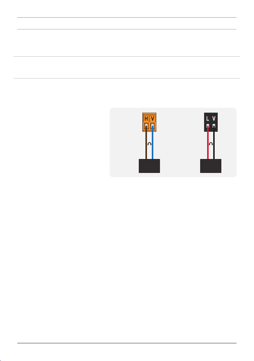
3.7 - Power supply
See 3.1F
DO NOT attempt to wire your controller while the power is on. NEVER connect your
low voltage controller to mains power.
Wire your controller for low or high voltage power supply, as show in the diagrams
below. Check the label on the unit against the colour of the connector:
› Orange =
High voltage (85–265V AC,
95–370V DC)
› Black =
Low voltage (15–48V AC,
High
voltage
(HV)
+DC
Live
AC
−DC
Neutral
AC
Low
voltage
(LV)
+DC
Live
AC
−DC
Neutral
AC
10–72V DC)
HV power
supply
LV power
supply
Once you have completed the wiring process it is safe to switch on your power
supply. Ensure that your display is functioning before you proceed.
PRO-PRC-MAN-17V01 (0802) Copyright © 2017 Dene Instruments
Page 8
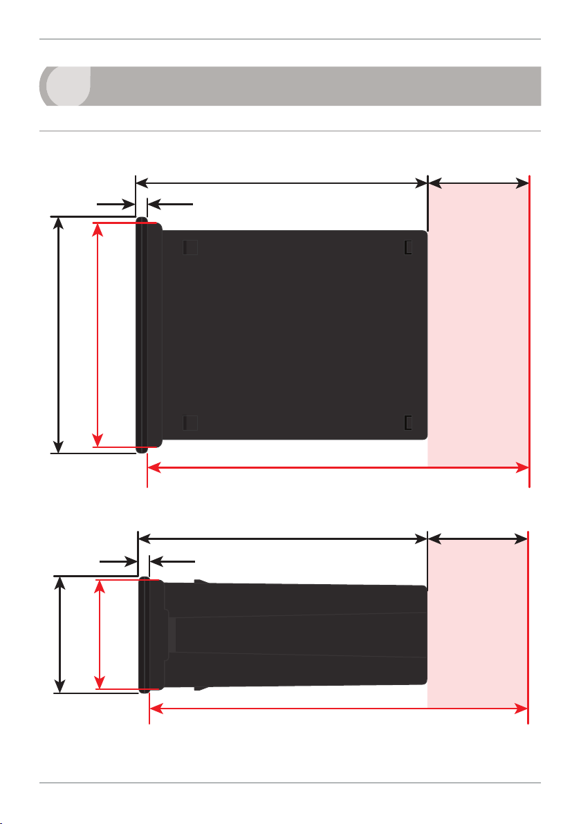
8
120
39
155mm (6.10") minimum depth required behind panel
4
DIMENSIONS & INSTALLATION
4.1 - Case dimensions
mm (0.16")
4
96
mm
92mm
(3.78")
(3.62")
mm (4.72")
mm (1.54")
Cabling
Allowance
155mm (6.10") minimum depth required behind panel
120 mm (4.72") 39mm (1.54")
mm (0.16")
4
mm
45mm
48
(1.89")
(1.77")
PRO-PRC-MAN-17V01 (0802) Copyright © 2017 Dene Instruments
Cabling
Allowance
Page 9
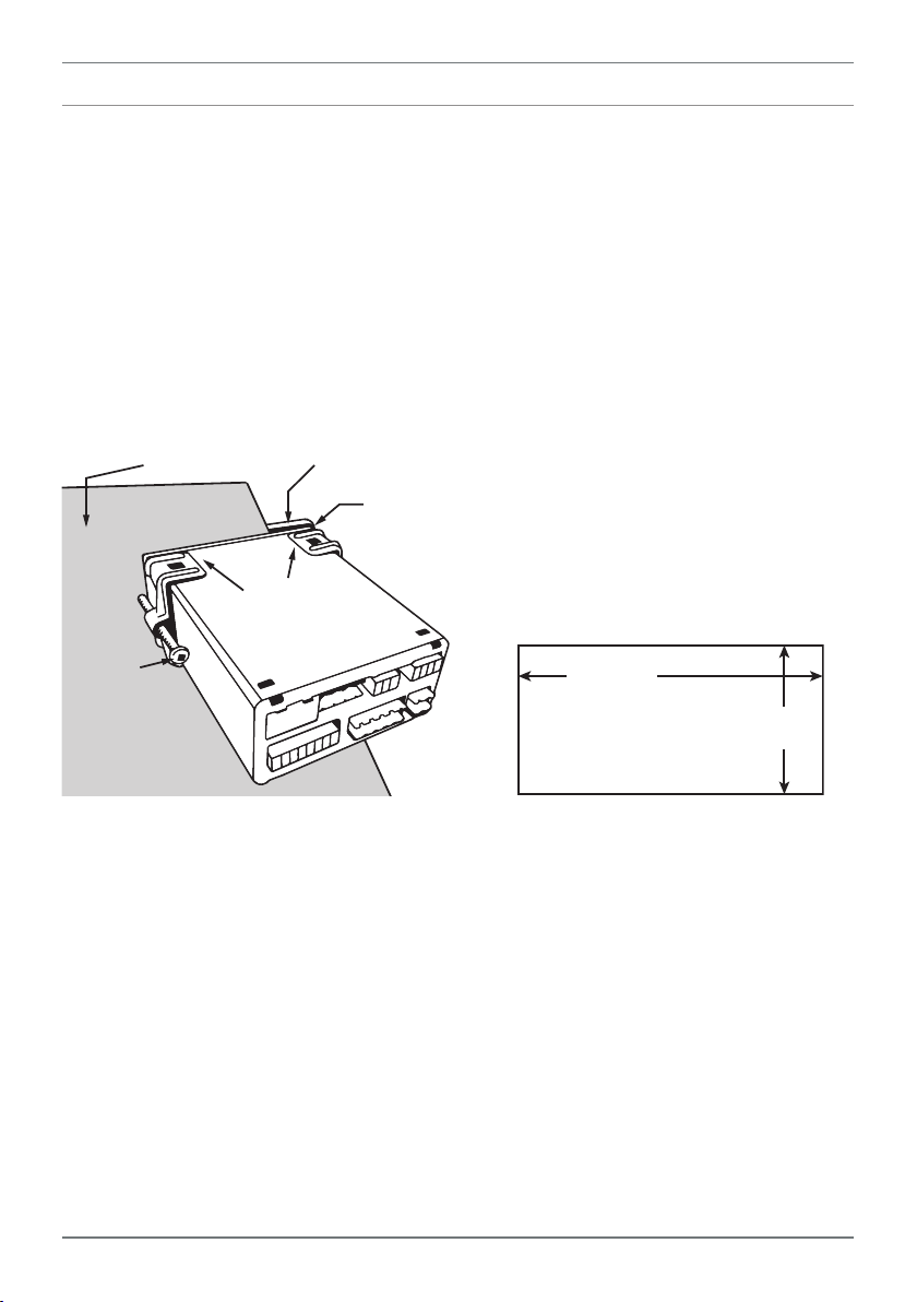
4.2 - Installation instructions
Panel Meter Faceplate
Panel Cutout
9
A Prepare the Panel Cutout to
92 x 45mm ±.5 (3.62 x 1.77" ±.02),
as shown below.
Allow at least 155mm (6.10")
depth behind the panel to accommodate the meter body, protruding connectors and cabling.
B Remove the Mounting Clips from
the meter back.
Panel
Gasket
Mounting
Clips
Screws
C Slide the Panel Gasket over the
rear of the unit to the back of the
Meter Faceplate.
D From the front of the panel, insert
the meter into the Panel Cutout.
Holding the unit in place, engage
the Mounting Clips so that the tabs
snap into place over the notches on
the case.
E To achieve a proper seal, tighten
the Screws evenly until the unit sits
rmly against the panel. Do not
over-tighten the screws.
92mm ±.5
(3.62″ ±.02)
45mm ±.5
(1.77″ ±.02)
PRO-PRC-MAN-17V01 (0802) Copyright © 2017 Dene Instruments
Page 10

10
5
INPUT SETUP & CALIBRATION
5.1 - Enter F1 PIN number
A Enter the calibration mode by pressing the button.
_ _ _ ENTER CAL PIN NUMBER scrolls across the display and toggles with 0.
Use the
press . If the correct PIN is entered, setup is started at 5.2.
If an incorrect PIN number is entered, _ _ _ INCORRECT PIN NUMBER – ACCESS
DENIED scrolls across the display and it returns to normal operating mode.
You will have the opportunity to change your PIN number at the end of this section
(5.8). If you have forgotten your PIN number, see Section 8.
and buttons to enter your security code (factory default 1). Then
5.2 - Input setup
A _ _ _ INPUT SETUP scrolls across the display and toggles with SKIP. Press to
skip to 5.3, or the button and then to ENTER input setup.
B _ _ _ MAINS FREQUENCY scrolls across the display and toggles with the current
selection. Use the
C _ _ _ AVERAGING SETUP scrolls across the display and toggles with SKIP. Press
now to skip, or use the and buttons to select a channel to set up
averaging for (CH 1, CH 2, CH 3 or CH 4), and then press .
¨ If you selected a channel, continue to 5.2D now.
¨ If you selected SKIP, skip to 5.3 now.
D _ _ _ AVERAGING SAMPLES scrolls across the display and toggles with the cur-
rent averaging. Using the
that the controller will average, and then press .
PRO-PRC-MAN-17V01 (0802) Copyright © 2017 Dene Instruments
and buttons to select 50HZ or 60HZ, and press .
and buttons, alter the number of input samples
Page 11

11
Input signal in counts
Sampling
This feature allows signal averaging of
each individual input channel, to optimise
stable measurement. (This is dierent
from Multi-Channel Averaging, which is
set up in 5.3I.)
If the change in input exceeds the averaging window value it will not average, ensuring fast response when there are large
dierences between readings.
Increasing the number of AVERAGING
SAMPLES will stabilise measurement, but
it will also slow down response rates.
Input exceeds
averaging window
Number
of samples
Averaging window
in displayed counts
E _ _ _ AVERAGING WINDOW scrolls across the display and toggles with the cur-
rently selected signal averaging window value. Using the and buttons,
alter the signal averaging window. Then press .
If your input signal contains large noise spikes, you can increase the size of the averaging window to ensure that these are still averaged. However, increasing the window size too far will reduce the ability of the controller to respond quickly to real changes in input signal. Setting AV-
ERAGING WINDOW to 0 will give continuous averaging as per the selected averaging samples.
F _ _ _ AVERAGING SETUP scrolls across the display and toggles with SKIP. You
are now back at 5.2C. To set up avarating for another input channel, proceeds
through steps 5.2C–F again. To continue to 5.3, select SKIP and then press .
5.3 - Display setup
A _ _ _ DISPLAY SETUP scrolls across the display and toggles with SKIP. Press
to skip to 5.4, or the button and then to ENTER display setup.
B _ _ _ DISPLAY SOURCE scrolls across the display and toggles with the currently
selected display source. Use the
CH 1, CH 2, CH 3, CH 4 or CH AVE. Then press .
¨ If you selected AUTO, continue to 5.3C now.
¨ If you selected something else, skip to 5.3D now.
In Auto mode, the main display constantly cycles through all available input channels (I.e. CH
1, followed by the current value for that channel, then CH 2,CH 3 etc). In CH AVE mode the
display will show the channel average value.
and buttons to choose between: AUTO,
PRO-PRC-MAN-17V01 (0802) Copyright © 2017 Dene Instruments
Page 12

12
C _ _ _ DISPLAY TIME IN SECONDS scrolls across and toggles with the current
selection. This setting is only used for AUTO display (see 5.3B), and is the pause
time (in seconds) between variables as they cycle on the display. Use the and
buttons to adjust this value as required, and then press .
D _ _ _ DECIMAL POINT/ROUNDING SETUP scrolls across and toggles with SKIP.
Press
now to skip decimal point and rounding setup, or use the and
buttons to select a channel: CH 1, CH 2, CH 3, CH 4 or CH AVE. Then press .
¨ If you selected a channel (or CH AVE), continue to 5.3E now.
¨ If you selected SKIP, skip to 5.3H now.
E _ _ _ DECIMAL POINT scrolls across the display and toggles with the current
decimal point position for the channel selected in 5.3D . Use the
and but-
tons to select: NONE, 0.1 , 0.01, 0.001, 0.0001 or 0.00001. Then press .
F _ _ _ ROUNDING scrolls across and toggles with the rounding for the selected
channel. Use the
Rounding is in display counts and is not inuenced by decimal point position.
and buttons to select: NONE, 2, 5, or 10. Press .
G _ _ _ DECIMAL POINT/ROUNDING SETUP scrolls across the display and tog-
gles with SKIP. You are now back at 5.3D. To set up another channel, proceed
through steps 5.3D–G again. To continue to 5.3H, select SKIP and press .
H _ _ _ PEAK/VALLEY SOURCE scrolls across the display and toggles with the
currently selected peak and valley source. Use the
and buttons to select:
DISP, CH 1, CH 2, CH 3, CH 4 or CH AVE, and then press .
DISP will use the current display source (selected in 5.3B) for the peak/valley display. (If your
display source [5.3B] is set to either 'PEAK' or 'VALLEY', then 'DISP' will not appear as an option, as this would create a circular reference.) CH AVE will use the channel average value.
Peak and valley can be viewed or reset via the main display using the front panel shortcuts (see
2.3), or reset via the rear pins (see 3.6).
I _ _ _ SELECT NUMBER OF CHANNELS FOR AVERAGE DISPLAY scrolls across
and toggles with the number of channels to be averaged to produce the CH
AVE value. Use and to select: NONE, 2 CH, 3 CH or 4 CH, and press .
CH AVE is an internally calculated value which is created by averaging 2, 3 or 4 of the input
channels, as selected above. The CH AVE value is stored by the controller and can be used as
the default view for the operational display, or as a source for analog output, serial output or
PRO-PRC-MAN-17V01 (0802) Copyright © 2017 Dene Instruments
Page 13

13
setpoint control. The controller will always select channels in sequential order, starting from 1.
(I.e. 2 CH will average channels 1 & 2. 3 CH will average channels 1, 2 & 3. 4 CH will average all
4 channels. Any other combination of channels is not possible.)
5.4 - Clock setup
A _ _ _ CLOCK SETUP scrolls across the display and toggles with SKIP. If you do
not wish to congure your clock now, press to skip to 5.5. Otherwise, press
the button and then to ENTER and set the date and time.
B _ _ _ HOURS scrolls across the display and toggles with the current selection.
Use the
C _ _ _ MINUTES scrolls across the display and toggles with the current selection.
Use the
Aer pressing the seconds timer will be reset to zero, and will immediately begin counting.
D _ _ _ DATE scrolls across the display and toggles with the current selection. Use
the and buttons to adjust the date (from 1 to 31), and press .
E _ _ _ MONTH scrolls across the display and toggles with the current selection.
Use the
and buttons to adjust the hour (from 0 to 23), and press .
and buttons to adjust the minutes (from 0 to 59), and press .
and buttons to select a month (from JAN to DEC), and press .
F _ _ _ YEAR scrolls across the display and toggles with the current selection. Use
and buttons to adjust the display to the current year, and press .
the
5.5 - Calibration
When calibration is complete, you will be directed back to the start of the calibration
menu (5.5A). To proceed to 5.6, you must select SKIP at 5.5A.
A _ _ _ CALIBRATE scrolls across the display and toggles with SKIP. Press
to skip to 5.6, or use the and buttons to select a channel to calibrate (CH
1, CH 2, CH 3 or CH 4), and then press .
B _ _ _ CAL MODE scrolls across and toggles with the currently selected calibra-
tion mode. Use the
and buttons to select AUTO or MAN (manual), and
PRO-PRC-MAN-17V01 (0802) Copyright © 2017 Dene Instruments
now
Page 14

14
then press .
¨ If you selected AUTO, complete steps 5.5C–E now.
¨ If you selected MAN, complete steps 5.5F–I now.
AUTO (key-in) is a 2-point calibration procedure that uses zero and span values to calculate
the scale and oset. MAN does not require any input signals. It allows the user to enter display
values for the low and high ends of the factory calibrated ranges (i.e. 4mA=0, 20mA=1000).
Auto calibration method
C _ _ _ APPLY LOW INPUT SIGNAL – – – –ENTER LOW DISPLAY VALUE scrolls
across the display, and the currently selected low display value appears. Apply
the required low level input signal to the meter, and wait a moment for the
signal to stabilise. Then use the
and buttons to set the required low level
display value, and press to accept.
D _ _ _ APPLY HIGH INPUT SIGNAL – – – –ENTER HIGH DISPLAY VALUE scrolls
across the display, and the currently selected high display value appears. Apply
the required high level input signal to the meter, and wait a moment for the
signal to stabilise. Then use the
and buttons to set the required high level
display value, and press to accept.
E If AUTO calibration was successful, you will be directed back to 5.5A to select
a new channel to calibrate. (To enter step 5.6, you must select SKIP at 5.5A.)
If calibration fails, _ _ _ CALIBRATION FAILED will scroll across the display twice,
and then you will be directed back to 5.5A to try calibrating again.
The most likely cause of this message is that the controller has not detected any change in input
signal during the calibration process. Check your signal and connections, and then repeat the
calibration procedure.
Manual calibration method
F _ _ _ INPUT RANGE scrolls across and toggles with the current selection. Use
the
and buttons to select 4-20MA or 0-20MA, and then press .
G _ _ _ ENTER DISPLAY VALUE FOR [LOW MA] scrolls across the display, and the
PRO-PRC-MAN-17V01 (0802) Copyright © 2017 Dene Instruments
Page 15

15
currently selected low display value appears. Use the and buttons to set
the display value for the low level input signal. Press to accept.
The text string for [LOW MA] will dier depending on your input range (selected in 5.5F): 0MA
(for 0–20mA) or 4MA (for 4–20mA).
H _ _ _ ENTER DISPLAY VALUE FOR 20MA scrolls across the display, and the cur-
rently selected high display value appears. Use the and buttons to set the
display value for the high level input signal. Press to accept.
I You will be directed back to 5.5A to select a new channel to calibrate. (To enter
step 5.6, you must select SKIP at 5.5A.)
5.6 - Analog output setup
A _ _ _ ANALOG OUTPUT SETUP scrolls across the display and toggles with SKIP.
If your controller does not have analog output installed, (or you do not wish to
congure your analog output now), press to skip to 5.7.
Otherwise, press the
button and then to ENTER analog output setup.
B _ _ _ DATA SOURCE FOR ANALOG O/P scrolls across the display and toggles
with the current analog output data source. Use the
and buttons to se-
lect an option from: CH 1, CH 2, CH 3, CH 4 or CH AVE. Then press .
C _ _ _ LOW SCALE VALUE FOR ANALOG O/P scrolls across the display and tog-
gles with the currently selected low scale display value. Use the
and but-
tons and buttons to enter your cal low position, and then press .
D _ _ _ HIGH SCALE VALUE FOR ANALOG O/P scrolls across the display and
toggles with the currently selected high scale display value. Use the
and
buttons to enter your cal high position, and then press .
E _ _ _ CALIBRATE ANALOG O/P? scrolls across and toggles with SKIP. Press
now to skip analog output calibration, or the button and then to ENTER.
PRO-PRC-MAN-17V01 (0802) Copyright © 2017 Dene Instruments
Page 16

16
¨ If you selected ENTER, continue to 5.6F now.
¨ If you selected SKIP, skip to 5.7 now.
F _ _ _ CAL LOW ANALOG O/P scrolls across the display and toggles with a cali-
bration number (shown in internal units). Before proceeding, connect a mA or
volt meter across the analog output connector (see 3.4). Then, using the
and
buttons, calibrate your low analog output as required. Press .
G _ _ _ CAL HIGH ANALOG O/P scrolls across the display and toggles with a
calibration number (shown in internal units). Using the
and buttons,
calibrate your high analog output as required. Then press .
5.7 - Serial setup
Refer to Appendix A for more information on serial modes and registers.
A _ _ _ SERIAL SETUP scrolls across the display and toggles with SKIP. If your
controller does not have a serial port installed, (or you do not wish to congure
your serial options now), please press
Otherwise, press the
button and then to ENTER serial setup.
to skip to 5.8.
B _ _ _ SERIAL MODE scrolls across the display and toggles with the current serial
mode. Use the
and buttons to choose between: ASCII (custom), MOD-
BUS (RTU), or RNGR A (Ranger A). Then press .
¨ If you selected ASCII or MODBUS, skip to 6.9D now.
¨ If you selected RNGR A, continue to 6.9C now.
ASCII is a simple, custom protocol that allows connection to various PC conguration tools.
(This is dierent from the Modbus ASCII protocol.) See A.1 for more information.
MODBUS (RTU) is an industry standard RTU slave mode that allows connection to a wide range
of devices, such as PC’s or PLC’s. See A.2 for more information.
PRO-PRC-MAN-17V01 (0802) Copyright © 2017 Dene Instruments
Page 17

17
RNGR A is a continuous output, used to drive instruments in the Rinstrum™ range. See A.3 for
more information.
C _ _ _ SERIAL DATA SOURCE scrolls across the display and toggles with the cur-
rently selected serial data source. Using the and buttons, selec t: DISP, CH 1,
CH 2, CH 3, CH 4 or CH AVE, and then press .
DISP will use the current display source (selected in 5.3B) for the serial data source, while
CH AVE will use the channel average value.
D _ _ _ BAUD RATE scrolls across the display and toggles with the current se-
lection. Use the and buttons to select one of: 1200, 2400, 4800, 9600,
19200, 38400, 57600 or 115200. Then press .
E _ _ _ PARITY scrolls across the display and toggles with the currently selected
parity. Using the
and buttons, select: NONE, ODD or EVEN, and then
press .
F _ _ _ SERIAL ADDRESS scrolls across the display and toggles with the currently
selected serial address. Use the
and buttons to alter the serial address,
and then press .
The serial address parameter is used to identify a particular device when it is used with other
devices in a system. (It applies particularly to MODBUS mode when used on an RS485 serial
network.) The serial address of the controller must be set to match the serial address dened
in the master device.
5.8 - Edit Cal PIN number
A _ _ _ EDIT CAL PIN NUMBER scrolls across the display and toggles with SKIP.
Press to skip and return to the operational display, or the button and
then to ENTER and change your PIN number.
B _ _ _ ENTER NEW CAL PIN NUMBER scrolls across the display and toggles with
the current PIN (default 1). Using the
PIN number. Then press to exit to the operational display.
and buttons, enter your new Cal
PRO-PRC-MAN-17V01 (0802) Copyright © 2017 Dene Instruments
Page 18

18
6
Your controller will allow conguration of up to 6 setpoints, however full
functionality is only supported when relay output hardware is installed.
(Setpoints with no corresponding relay output hardware may be used as simple LED
indicators, if desired. In this case, features requiring relay output functionality will
continue to appear in the setup menu, but will be ignored by the controller.)
SETPOINT SETUP
6.1 - Enter SP PIN number
A Enter setpoint setup mode by pressing and holding the button for 3 seconds.
_ _ _ ENTER SP PIN NUMBER scrolls across the display and toggles with 0. Use
the
press . If the correct PIN is entered, setup is started at 6.2.
If an incorrect PIN number is entered, _ _ _ INCORRECT PIN – ACCESS DENIED
scrolls across the display and it returns to normal operating mode.
You will have the opportunity to change your PIN number at the end of this section
(6.3). If you have forgotten your PIN number, see Section 8.
and buttons to enter your security code (factory default 1). Then
6.2 - Setpoint setup
A _ _ _ EDIT SETPOINT scrolls across the display and toggles with SKIP. Press
now to skip to 6.3, or use the and buttons to select a setpoint to edit,
and then press .
B _ _ _ SP VALUE scrolls across the display and toggles with the current value for
the selected setpoint. Using the
which the selected setpoint will activate, and then press .
PRO-PRC-MAN-17V01 (0802) Copyright © 2017 Dene Instruments
and buttons, adjust the display value at
Page 19

19
Energised Above
Energised Above
C The step that you proceed to now will depend on which setpoint you are editing
(selected in 6.2A):
¨ If you are currently editing SP 1, skip to 6.2E now.
¨ If you are currently editing SP 2–6, continue to 6.2D now.
D _ _ _ TRACK SP1 scrolls across the display and toggles with the tracking setting
for the selected setpoint. Using the
and buttons, select OFF or ON, and
then press .
¨ If you selected OFF, continue to 6.2E now.
¨ If you selected ON, skip to 6.2F now.
A setpoint with TRACK SP1 enabled will track the setpoint value of SP 1, with the setpoint
value of the tracking setpoint becoming an oset value.
E _ _ _ SP SOURCE scrolls across the display and toggles with the activation source
for the selected setpoint. Use the and buttons to select an option from:
CH 1, CH 2, CH 3, CH 4 or CH AVE, and then press .
F _ _ _ SP ACTIVATION scrolls across the display and toggles with the current ac-
tivation for the selected setpoint. Using the
and buttons, select the relay
activation to operate ABOVE or BELOW the setpoint value, and then press .
ABOVE: Relay turns on above the setpoint value and o below it. BELOW: Relay turns on below
the setpoint value and o above it.
G _ _ _ SP TYPE scrolls across the display and toggles with the hysteresis type for
the selected setpoint. Using the and buttons, select either ALARM or
CNTRL (control), and then press .
ALARM - SETPOINT VALUE controls setpoint
activation point. HYSTERESIS VALUE controls
setpoint deactivation point.
Hysteresis
band
Hysteresis
band
Energised Below
CNTRL - SETPOINT VALUE controls setpoint
deactivation point. HYSTERESIS VALUE con-
trols setpoint reactivation point.
Hysteresis
band
Hysteresis
band
Energised Below
H _ _ _ HYSTERESIS VALUE scrolls across the display and toggles with the hyster-
esis value for the selected setpoint. Use the and buttons to adjust this
value if required, and then press .
PRO-PRC-MAN-17V01 (0802) Copyright © 2017 Dene Instruments
Page 20

20
The HYSTERESIS VALUE denes the separation band between setpoint activation and deacti-
vation, and will operate as per the SP TYPE setting selected in 6.2G.
I _ _ _ MAKE DELAY scrolls across the display and toggles with the current make
delay time for the selected setpoint. This is the time delay between setpoint ac-
tivation, and when the relay turns on. Adjust this value in 0.1 second increments
using the and buttons, and then press .
J _ _ _ USER ACCESS? scrolls across the display and toggles with the direct access
permission setting for the selected setpoint. Use the
and to select either
OFF or ON, and then press .
When enabled, this option allows the selected setpoint's value to be edited directly aer pressing the
tions. Each setpoint can individually have this option enabled or disabled. See Section 7.
button, without needing to enter a PIN number or go through all of the other op-
K _ _ _ EDIT SETPOINT scrolls across the display and toggles with SKIP. You are
now back at 6.2A. To edit another setpoint, follow the instructions from 6.2A–K
again. If you do not wish to edit another setpoint, press now to skip to 6.3.
6.3 - Edit SP PIN number
A _ _ _ EDIT SP PIN NUMBER scrolls across the display and toggles with SKIP.
Press to skip and return to the operational display, or the button and
then to ENTER and change your PIN number.
B _ _ _ ENTER NEW SP PIN NUMBER scrolls across the display and toggles with
the current PIN (default 1). Using the
and buttons, enter your new SP PIN
number. Then press to exit to the operational display.
PRO-PRC-MAN-17V01 (0802) Copyright © 2017 Dene Instruments
Page 21

21
7
When this feature is enabled, the selected setpoint will be editable via the
button without entering a PIN.
If none of the setpoints have their direct access option enabled in 6.2J then this
feature will be disabled and the
A Begin by pressing the
B The name of the rst access-enabled setpoint will appear on the display and
toggle with the current value for that setpoint. Using the
adjust the selected value. Then press to accept and continue.
C The name of the next access-enabled setpoint will appear on the display, along
with its setpoint value. Repeat step 7B. The direct access menu will proceed
through all access-enabled setpoints in this fashion. Pressing
bled setpoint will exit and return to the operational display.
8
SETPOINT DIRECT ACCESS
button will not respond to a short button press.
button for less than 3 seconds.
and buttons,
for the last ena-
RESET PIN NUMBERS / VIEW FIRMWARE VERSION
If you have forgotten your PIN number(s), follow the procedure below to reset both
the Cal and SP PINs to their factory default of 1.
This procedure will also allow you to view the current soware installed on your
controller, which may be required for support purposes.
A Press
execute and you may need several tries to get it right.)
B A message will appear on the display, with details of the unit's current soware
conguration (Product Name, Firmware Version, and Macro Version). At the
end, you will see – ALL PIN NUMBERS RESET TO 1.
C Reset the default PIN numbers if required by following the instructions in 5.8
and 6.3, entering ‘1’ whenever you are prompted for your current PIN.
, and at the same time. (This key combination can be dicult to
PRO-PRC-MAN-17V01 (0802) Copyright © 2017 Dene Instruments
Page 22

22
A
APPENDIX A - SERIAL MODES
A.1 - Custom ASCII mode
Custom ASCII is a simple, custom protocol that allows connection to various PC con-
guration tools. ('Custom ASCII' diers from the 'Modbus (ASCII)' protocol used by
some devices.) Custom ASCII command strings must be constructed in this order:
<Start> <Controller Address> <Read/Write Command> <Register Address>
<Separator Character> <Data Value> <Message Terminator>
Start - Use 'S' for the start character of a command string (not case sensitive). This
must be the rst character in the string.
Controller Address - Use an ASCII number from '1' to '255' for the controller address.
If the character following the start character is not an ASCII number, then address '0' is assumed. All controllers respond to address '0'.
Read/Write Command - Use ASCII 'R' for read, 'U' for unformatted read, or 'W' for
write (not case sensitive). Any other character aborts the operation.
In Custom ASCII mode, data is normally read as formatted (which includes decimals and any
text characters that may be selected to show units). However it is also possible to read unformatted data by using a 'U' in the read command. There is no unformatted write command, as
when writing to xed point registers, any decimal point and text characters are ignored.
Register Address - The register address for the read/write operation will be an ASCII
number from '1' to '65535'. This character must be specied for a write com-
mand, but may be omitted for a read command, (in which case the controller
will respond with the data value currently on the display).
Separator Character - The separator character can be either a space or a comma,
and is used to separate the register address from the data value.
Data Value - Must be an ASCII number. The absolute limits for this number are
–
1000000 to +1000000, but note that not all registers will accept this range.
Message Terminator - This is the last character, and must be either a '$' (dollar) or
an '*' (asterisk). Neither of these characters should be used elsewhere in the
PRO-PRC-MAN-17V01 (0802) Copyright © 2017 Dene Instruments
Page 23

23
message string. If '$' is used, a 50ms minimum delay is inserted before a reply is
sent. If '*' is used, a 2ms minimum delay is inserted before a reply is sent.
Custom ASCII Read/Write Examples
Example Description
SR$ Read display value from all controllers, 50ms delay.
S15R$ Read display value from controller address 15, 50ms delay.
S3U40* Read unformatted data in channel 4 from controller address 3, 2ms delay.
–
S2W2 –10000$ Write
SWT CHAN_1$ Write ASCII text string Chan_1 to channel 1 text register, 50ms delay.
10000 to the display register of controller address 2, 50ms delay.
Custom ASCII Registers - Active for models with relay output installed
8 Bit Unsigned
Address Function
8207 Baudrate
8211 Serial address
8215 Serial mode
16 Bit Unsigned
Address Function
4181–
4184
4197–
4200
Note: Address 16543 is a read/write null
terminated text string, into which you can
write your own identication text (up to 62
characters).
Hysteresis (SP1=4181, SP2=4182,
SP3 =4183, SP4=4184)
Make delay (SP1=4197,
SP2=4198, SP 3=4199, SP4=4200)
32 Bit Signed
Address Function
7 Process CH 1
17 Process CH 2
19 Process CH 3
21 Process CH 4
39 Process average
57 Peak
59 Valley
111 Setpoint 1
113 Setpoint 2
115 Setpoint 3
117 Setpoint 4
239 Alarm status
381 D/A scale low value
405 D/A scale high value
Controller Response - Aer the controller has completed a read or write instruction,
it responds by sending a carriage return/line feed (CR/LF) back to the host. If
the instruction was a read command, the CR/LF follows the last character in the
PRO-PRC-MAN-17V01 (0802) Copyright © 2017 Dene Instruments
Page 24

24
ASCII string. If it was a write command, CR/LF is the only response sent back.
The host must wait for this before sending further commands to the controller.
If the controller encounters an error, it will respond with a null (0x00) CR/LF.
A.2 - Modbus (RTU) mode
Modbus (RTU) is an industry standard RTU slave mode that allows connection to a
wide range of devices. Modbus registers are all holding registers, and should be ac-
cessed via function codes 3 and 6.
Register addresses are displayed in the Modicon™ 5-digit addressing format. I.e.
Register 65=400065 (subtract 1 for direct addressing).
Modbus (RTU) Registers - Active for models with relay output installed
8 Bit Unsigned
Address Function
408207 Baudrate
408211 Serial address
408215 Serial mode
16 Bit Unsigned
Address Function
404181–
404184
404197–
404200
Note: Address 416543 is a read/write null terminated text string, into which you can write
your own identication text (up to 62 characters). This is accessed using a standard Modbus
read/write command for holding registers, where each 16 bit register holds 2 x ASCII string
characters in sequence.
Hysteresis (SP1=404181, SP2=
404182, SP3=404183, SP4=
404184)
Make delay (SP1=404197, SP2=
404198, SP3=404199, SP4=
404200)
32 Bit Signed (2 x 16 Bit)
LSW MSW Function
400007 400008 Process CH 1
400017 400018 Process CH 2
400019 400020 Process CH 3
400021 400022 Process CH 4
400039 400040 Process average
400057 400058 Peak
400059 400060 Valley
40 0111 400112 Setpoint 1
400113 400114 Setpoint 2
400115 400116 Setpoint 3
400117 400118 Setpoint 4
400239 400240 Alarm status
40587 40588 D/A scale low value
40591 40592 D/A scale high value
PRO-PRC-MAN-17V01 (0802) Copyright © 2017 Dene Instruments
Page 25

25
A.3 - Ranger A mode
Ranger A is a continuous output, used to drive remote displays and other instru-
ments in the Rinstrum™ range. (Ranger is a trade name belonging to Rinstrum Pty
Ltd.) Ranger A output strings are constructed as shown:
<Start> <Sign> <Output Value> <Status> <End>
Start - STX character (ASCII 02)
Sign - Output value sign (space for + and dash for -)
Output Value - Seven character ASCII string containing the current output value and
decimal point. (If there is no decimal point, then the rst character is a space.
Leading zero blanking applies.)
Status - Single character output value status. 'U'=Under, 'O'=Over, 'E'=Error.
End - ETX character (ASCII 03)
PRO-PRC-MAN-17V01 (0802) Copyright © 2017 Dene Instruments
Page 26

26
PRO-PRC-MAN-17V01 (0802) Copyright © 2017 Dene Instruments
Page 27

27
PRO-PRC-MAN-17V01 (0802) Copyright © 2017 Dene Instruments
Page 28

De ne Instruments
New Zealand
(Head O ce)
Auckland 0632, New Zealand
Auckland 0661, New Zealand
Ph
Fax
www.de neinstruments.co.nz
10B Vega Place, Rosedale,
PO Box 245 Westpark Village,
: +64 (9) 835 1550
: +64 (9) 835 1250
sales@de neinstruments.co.nz
PRO-PRC MV2.3 Document Revision Code: PRO-PRC-MAN-17V01 Date Code: 170802
United States (Dallas, TX)
Ph: (214) 926 4950
sales@de neinstruments.com
www.de neinstruments.com
South Africa (Pretoria)
sales@de neinstruments.co.za
www.de neinstruments.co.za
 Loading...