

Page 1
1
PRO-FLO200
Flow Rate Totalizer
This sophisticated panel mount control-
ler is the ideal solution for a variety of
ow rate applications, and is designed
for simple setup and operation.
It features a customizable dual display,
user programmable input functions,
and simple calibration using K factor en-
try, or pulses per unit of measurement.
Advanced setpoint modes are available,
including timed or latched types, and
the totalizer features batch counting
and volumetric pulse.
Order Codes
PRO-FLO200
-HV 85-265V AC / 95-370V DC
-LV 15-48V AC / 10-72V DC
Options
-R2 2 x relay outputs
-R4 4 x relay outputs
-R6 6 x relay outputs (5 active)
-A 1 x mA/V analog output
-S2R 1 x RS232 (RJ11 terminal)
-S4S 1 x RS485 (screw terminal)
Contents
1 - Specications .............................. 2
2 - Features ...................................... 3
3 - Front Panel & Display ................. 5
4 - Wiring ......................................... 7
5 - Dimensions & Installation.........11
6 - Input Header Adjustment ........ 13
7 - Input Setup & Calibration ........ 15
8 - Setpoint Setup.......................... 23
9 - Setpoint Direct Access ............. 30
10 - Reset PIN Numbers / View
Firmware version ..................... 30
Appendix A - Serial Modes ............. 31
PRO-FLO200-MAN-19V01 (0220)Copyright © 2019 Dene Instruments
Page 2

2
1
SPECIFICATIONS
General Specications
Sensor type NPN (open collector), PNP,
Mag (20mV to 30V), TTL, digital, closed
contact or namur
Input 0–24V DC, 0–30V AC
Power supply
HV: 85–265V AC/95–370V DC OR
LV: 15–48V AC/10–72V DC
Sensor calibration using direct K
factor entry or pulses per unit of
measurement
K factor ranges 3 ranges for K fac-
tors, from 0.1 to 99.9999, 999.999 or
9999.99
Flow rate /sec, /min or /hour; use
multiplier (x0.0001–1000) to display
required units
Relay Output
OPTIONAL
Number of relay outputs
None, 2, 4 or 6
Note that the rst relay (SP 1/BCH SP) is
reserved for batching functions
SP 6 is disabled and cannot be used, even
when 6 relay outputs are installed
Relay output type 5A form A (3A 240V
AC max or 3A 30V DC max)
Analog Output
OPTIONAL
Number of analog outputs None or 1
Analog output type Isolated 16 bit
4–20mA/0–10V
Wire for either current or voltage. Fully
scalable. Window programmable over any
range within the controller's full-scale range.
Comm Port
OPTIONAL
3
6
Totalizer resolution x1, x10
, x10
Volumetric pulse with adjustable pulse
width from 0.1 to 10.0 seconds
Number of comm ports None or 1
Comm port options
S2R= Isolated RS232, RJ terminal, or
S4S= Isolated RS485, screw terminal
Frequency 2Hz to 10KHz
Serial output Custom ASCII, Modbus
Excitation 24V DC (50mA max) pro-
RTU slave or Ranger A
vided by controller
Data rate 1200–115k2 baud
Accuracy 0.005%
Parity Odd, even or none
Temperature dri Typically 2ppm/°C
PRO-FLO200-MAN-19V01 (0220) Copyright © 2019 Dene Instruments
Page 3

3
Programming
Front panel buttons Up, Down, P
(Prog/Enter), plus 2 Menu buttons (F)
Security Input and setpoint setups
are independently accessible and PIN
protected
Display
Display type 14 segment alphanumeric
LED display, 5 buttons
Digits 2 x 6 digits, 0.4" (10mm)
LED indicators 6 setpoint LED's (5
active)
2
FEATURES
Construction
Casing Panel mount case
Ingress protection rating IP65 dust/
splash proof (face only)
Dimensions (H x W x D)
1.89 x 3.78 x 4.72" (48 x 96 x 120mm)
Panel cutout 1.77 x 3.62" (45 x 92mm)
2.1 - Advanced Setpoint Types
There are three setpoint types available for this model:
› A normal setpoint will activate and deactivate using alarm or control logic (see
8.2J) regulated within a hysteresis band (see 8.2K).
› A timed setpoint will activate as normal, and remain active for a user defined
time period (see 8.2O), after which it will deactivate automatically.
› A latched setpoint will activate as normal, and remain active until it is unlatched
either by setpoint logic (see 8.2Q), or manually using a user shortcut pin/key
(see 7.6).
PRO-FLO200-MAN-19V01 (0220)Copyright © 2019 Dene Instruments
Page 4

4
2.2 - Batching
This function allows the Total count to be maintained, as well as the current batch
value. This allows the user to maintain the total in the background, while still allow-
ing set batch amounts to be measured. The batching feature uses the calculation:
Batch = Total – Batch Tare.
Batch Tare is reset to the Total value when a reset batch function is triggered via
setpoint logic (see 8.2Q) or a user shortcut pin/key (see 7.6).
Batch Count allows the user to count how many completed batches have been pro-
cessed. The Batch Count Modier (see 8.2U) value (usually 1 or -1) is added to
the Batch Count register each time the Batch Setpoint is activated, as per the
selected Reset Edge (see 8.2S).
2.3 - Input Signal Averaging
Input signal averaging reduces noise and optimizes stable measurement.
If your input signal contains large noise spikes, you can increase the size of the aver-
aging window to ensure that these are still averaged. If the change in input exceeds
the averaging window value it will not average, ensuring fast response when there
are large dierences between readings. Increasing the window size too far will re-
duce the ability of the controller to respond quickly to real changes in input signal.
2.4 - Startup Inhibit
This feature can be used with setpoints which may be active initially at power up. It
will cause a relay to remain o (de-energized) at power up until it has rst reached
its inactive state, aer which it will function normally.
2.5 - Volumetric Pulse
This function is ideal for feeding volume information to other equipment. It outputs
a pulse on the relay when Total ≥ Setpoint Value, causing the relay to activate for a
PRO-FLO200-MAN-19V01 (0220) Copyright © 2019 Dene Instruments
Page 5
5
specied length of time (see 8.2G), which can be adjusted to suit the requirements
of externally connected devices.
When a setpoint is activated in volumetric pulse mode, the totalizer will reset using
the calculation: Total = Total – Setpoint Value, and then resume totalizing.
3
FRONT PANEL & DISPLAY
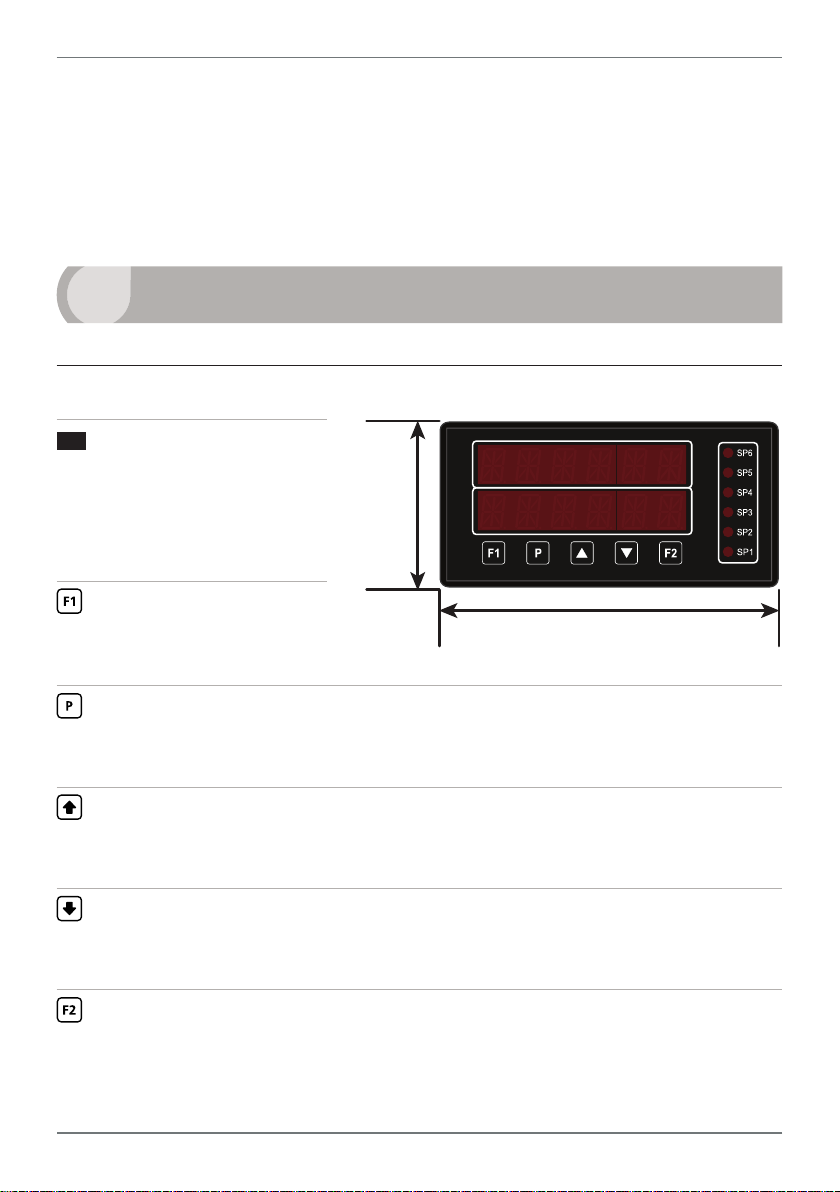
3.1 - Front panel
SPX
The SP LED's are used to
indicate active setpoints.
SP1 is used to indicate the
BCH SP. SP6 is perma-
nently disabled.
Used to access the Input
Setup & Calibration menu
(Section 7).
Used to save your settings and advance to the next step. It can also be cong-
ured to perform a user-selected custom function aer a long press (> 2secs)
from the main display (see 7.6B).
Typically used to scroll through options or increase values in the setup menu.
Pressing this button from the main display will show the current values for
Rate, Batch and Peak (see 3.3).
48mm
(1.89")
96mm (3.78")
Typically used to scroll through options or decrease values in the setup menu.
Pressing this button from the main display will show the current values for
Total, Batch Count, Inight Correction and Valley (see 3.3).
Used to access the Setpoint Setup menu (Section 8) and the Setpoint Direct
Access menu (Section 9).
PRO-FLO200-MAN-19V01 (0220)Copyright © 2019 Dene Instruments
Page 6
6
3.2 - Display brightness
To adjust the display brightness, press the and buttons together from the
main display. BRI appears and toggles with the current setting. Use the and
buttons to adjust the LED backlight, and then press to return to the normal
operating mode.
3.3 - Up and down button shortcuts
Pressing the and buttons from the main operational display allows instant
access to a number of values held in the controller's memory. These variables will ap-
pear in the order shown in the table below, and will cycle continuously at each press
of the or button.
Press
at any time to return to normal operating mode. The PEAK, VALLEY, TO-
TAL and BT CNT values may be reset to zero by pressing the and buttons at
the same time while the variable is being displayed.
Up and down button shortcuts
RATE The current ow rate input
BATCH The batch value
PEAK The maximum measured ow rate input since the instrument was turned on
or reset
TOTAL The totalizer value
BT CNT The number of batches that have been processed (batch count)
INFLIT Inight correction oset: This value is calculated by the controller based on
the batch error (the dierence between the batch setpoint value and the
nal batch value) averaged over the last three batches, and the Inight Adjustment Delay time (selected in 8.2W)
VALLEY The minimum measured ow rate input since the instrument was turned on
or reset
PRO-FLO200-MAN-19V01 (0220) Copyright © 2019 Dene Instruments
Page 7
7
4
BEFORE YOU BEGIN WIRING, ensure that the unit is switched o and the power
supply is disconnected.
WIRING
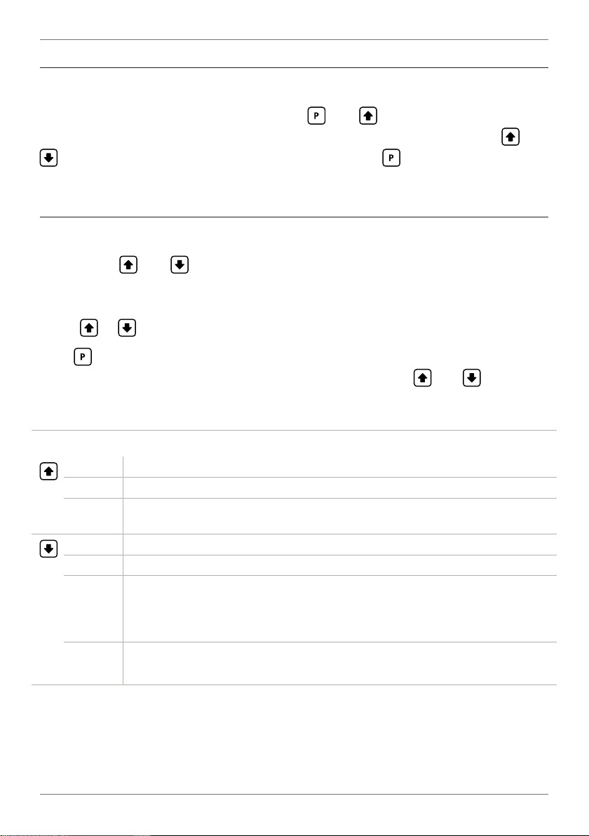
4.1 - Pinouts
A B C
Key
4.1A Relay Output (See 4.3)
4.1B Serial Port (See 4.5)
4.1C Analog Output (See 4.4)
4.1D Analog Input (See 4.2)
4.1E Function Pins (See 4.6)
D
E
F
4.1F Power Supply (See 4.7)
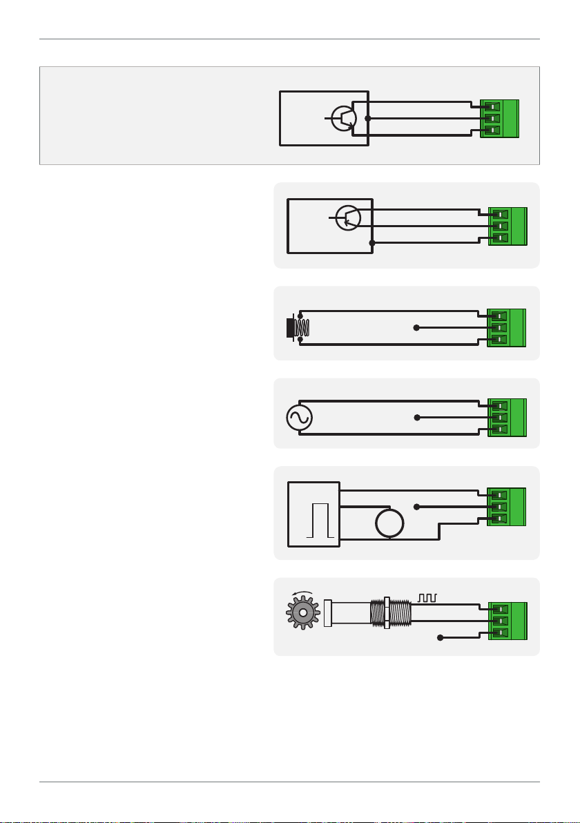
4.2 - Wire the Analog Input Module See 4.1D
IMPORTANT: The input module for this unit has four headers which are factory
congured to suit your application. The unit is congured for an NPN type sensor
by default.
¨ If you are using an NPN type sensor, you don't need to change anything.
¨ If you are using PNP, TTL, Namur, Tacho, or a Pushbutton switch, please
review your header configuration before continuing, referring to Section 6.
Then wire your input as required, referring to the diagrams on the following page.
PRO-FLO200-MAN-19V01 (0220)Copyright © 2019 Dene Instruments
Page 8
8
SIGNAL
SIGNAL
SIGNAL
SIGNAL
SIGNAL
NPN open collector output with
proximity switch
› Active sensor signal: 0V
› Inactive sensor signal: +24V
PNP open collector output with
proximity switch
› Active sensor signal: +24V
› Inactive sensor signal: 0V
Push button switch
NPN
Open
collector
output
PNP
Open
collector
output
+ Supply
-- Supply
+ Supply
-- Supply
+ 24V EXC
GND
+ 24V EXC
GND
› Open signal: +24V
› Closed signal: 0V
Tacho generator sensor
TTL input
› In this example the TTL logic has
a separate +5V power supply
Namur sensor
› Active sensor signal: 0.3–1.0mA
› Inactive sensor signal:
1.7–3.0mA
PUSHBUTTON
SWITCH
AC INPUT
Max 30V AC
TTL
5V
0V
NAMUR
SENSOR
+ Supply
-- Supply
DC
Supply
N/C
N/C
N/C
+ 24V EXC
GND
+ 24V EXC
GND
+ 24V EXC
GND
SIGNAL
+ 24V EXC
GND
N/C
PRO-FLO200-MAN-19V01 (0220) Copyright © 2019 Dene Instruments
Page 9
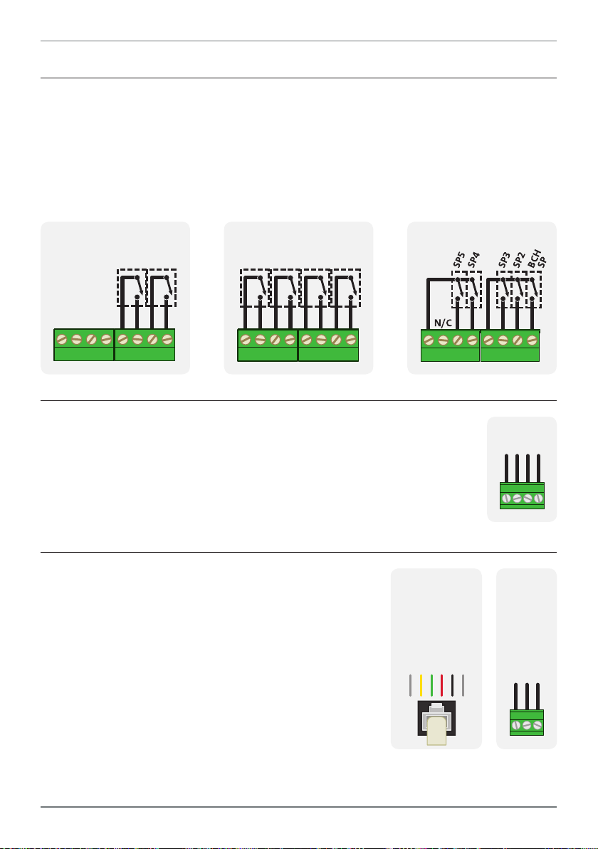
4.3 - Wire the Relay Outputs See 4.1A
SP2 BCH SP
BCH SP
+mA
N/C
If your controller has relay outputs tted, wire them as shown below. Please note:
› SP 1 is always treated as a Batch Setpoint (BCH SP)
› SP 6 is used by the controller for internal calculations. It does not appear in the
setpoint menu, and its relay output functionality has been deactivated.
9
-R2
-R4 -R6
SP4 SP3
SP2
4.4 - Wire the Analog Output
See 4.1C
If your controller has analog output tted, wire it as shown for either
voltage (0–10V) or current (4–20mA).
4.5 - Wire the Serial Port
See 4.1B
If your controller has serial port tted, wire it as shown
in the applicable diagram. (S2R: RS232, RJ11 terminal,
S4S: RS485, screw terminal).
N/C
-S2R
SGND
+5V DC (option)
RXD
TXD
–V+V–mA
-S4S
D -D +
SGND
PRO-FLO200-MAN-19V01 (0220)Copyright © 2019 Dene Instruments
Page 10
10
User 1 Tes tUser 2
User 3
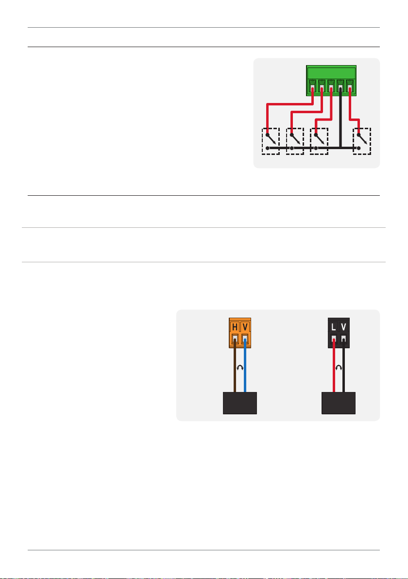
4.6 - Wire the Function Pins
See 4.1E
Connect external switches to enable a function to
be executed when its switch is activated.
› User 1–3: Activating one of these function
pins will execute its user-defined function (as
specified in 7.6C–E)
› Test : Activating this pin resets the unit
COM
4.7 - Wire the Power Supply See 4.1F
DO NOT attempt to wire your controller while the power is on. NEVER connect your
low voltage controller to mains power.
Wire your controller for low or high voltage power supply, as show in the diagrams
below. Check the label on the unit against the color of the connector:
› Orange =
High voltage (85–265V AC,
95–370V DC)
› Black =
Low voltage (15–48V AC,
High
voltage
(HV)
+DC
Live
AC
−DC
Neutral
AC
Low
voltage
(LV)
+DC
Live
10–72V DC)
HV power
Once you have completed the
supply
wiring process it is safe to switch
on your power supply. Ensure
that your display is functioning before you proceed.
PRO-FLO200-MAN-19V01 (0220) Copyright © 2019 Dene Instruments
AC
LV power
supply
−DC
Neutral
AC
Page 11
11
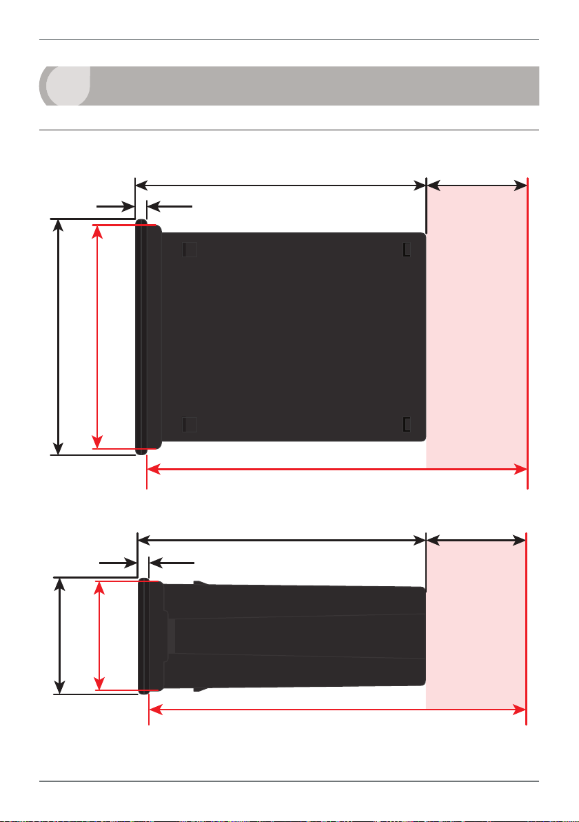
120
39
155mm (6.10") minimum depth required behind panel
5
DIMENSIONS & INSTALLATION
5.1 - Case Dimensions
mm (0.16")
4
96
mm
92mm
(3.78")
(3.62")
155mm (6.10") minimum depth required behind panel
mm (4.72")
mm (1.54")
Cabling
Allowance
mm
48
(1.89")
120 mm (4.72") 39mm (1.54")
mm (0.16")
4
45mm
(1.77")
Cabling
Allowance
PRO-FLO200-MAN-19V01 (0220)Copyright © 2019 Dene Instruments
Page 12

12
Panel Meter Faceplate
Panel Cutout
5.2 - Installation Instructions
A Prepare the Panel Cutout to
3.62 x 1.77" ±.02 (92 x 45mm ±.5),
as shown below.
Allow at least 6.10" (155mm)
depth behind the panel to accommodate the meter body, protruding connectors and cabling.
B Remove the Mounting Clips from
the meter back.
Panel
Gasket
Mounting
Clips
Screws
C Slide the Panel Gasket over the
rear of the unit to the back of the
Meter Faceplate.
D From the front of the panel, insert
the meter into the Panel Cutout.
Holding the unit in place, engage
the Mounting Clips so that the tabs
snap into place over the notches on
the case.
E To achieve a proper seal, tighten
the Screws evenly until the unit sits
rmly against the panel. Do not
over-tighten the screws.
92mm ±.5
(3.62″ ±.02)
45mm ±.5
(1.77″ ±.02)
PRO-FLO200-MAN-19V01 (0220) Copyright © 2019 Dene Instruments
Page 13

13
2006 © 502A IF-11
6
INPUT HEADER ADJUSTMENT
We recommend that you specify your sensor type when you place your order, to
avoid unnecessary removal of the input module.
6.1 - Input Header Settings
The analog input board for the PRO-FLO200 has four headers which aect the Low
Pass Filter (A), Mode (B), Input Signal (C) and Load (D). Of these, headers A, C and
D should be adjusted as required for your sensor type.
Refer to the tables below
to determine whether
the default header
positions (highlighted
black) are suitable for
your application.
If required, follow the instruc-
tions in 6.2 to remove the ana-
log input board from the meter case and adjust the header positions as needed.
Low Pass Filter
20KHz
2KHz
200Hz
OFF
SOURCE
NAMUR
D
TACH
SINK
A
Mag Pickup
Load
Input Signal
C
Logic
Counter
FREQ
B
Low Pass Filter Header (A)
OFF Ideal for high-speed counting
200Hz Ideal for mechanical contacts
2KHz Suitable for a noisy signal
20KHz Suitable for a noisy signal
Mode Header (B) - Do not adjust!
Counter Always use this setting
FREQ Not used for PRO-FLO200
Input Signal Header (C)
Logic NPN, PNP, Namur, TTL &
Pushbuttons
Mag Pickup Tach o
Load Header (D)
SINK NPN, TTL & Pushbuttons
SOURCE PNP
NAMUR Namur
TACH Tacho
PRO-FLO200-MAN-19V01 (0220)Copyright © 2019 Dene Instruments
Page 14

14
6.2 - How to Remove the Input Module
A If the meter is already installed, remove it from the panel, and unplug all plugs
from the back of the unit.
B Using a small screwdriver or similar implement,
press downward into one of the slots at the
rear of the case. This will disengage one of
the tabs which holds the back plate on, al-
lowing it to be gently levered away at
one corner.
C Holding the loosened corner open
with one hand, disengage the le-
ver on the opposite slot (Fig 1).
D You should now be able to remove the back plate. If it does not unclip easily,
you may need to disengage the two remaining tabs by repeating steps 6.2B–C
on the other side of the meter.
FIG 1
E Slide the analog input module out
of the meter case (Fig 2). (See 4.1D
to identify the input module.)
F Position the headers on the input
module as required for your sensor
type, referring to 6.1.
G Slide the input module back into
the meter case.
Make sure that it is sitting in the tracks on the le and right. Press rmly until the input module
is fully inserted and sits ush with the other boards that are visible from the back of the meter.
H Replace the back plate.
Begin by inserting the two lower tabs into the slots, and then position the upper tabs so that
they will not catch on the top lip of the meter case. Apply rm pressure until the back plate
clicks into place.
I Reconnect the plugs and return the meter to the panel installation.
PRO-FLO200-MAN-19V01 (0220) Copyright © 2019 Dene Instruments
Page 15

15
7
INPUT SETUP & CALIBRATION
7.1 - Enter F1 PIN Number
A Enter the calibration mode by pressing the button.
_ _ _ ENTER F1 PIN NUMBER scrolls across the bottom row and 0 appears in the
top row. Use the
1). Then press . If the correct PIN is entered, setup is started at 7.2.
If an incorrect PIN number is entered, _ _ _ INCORRECT PIN NUMBER – ACCESS
DENIED scrolls across the display and it returns to normal operating mode.
You will have the opportunity to change your PIN number at the end of this section
(7.9). If you have forgotten your PIN number, see Section 10.
and buttons to enter your security code (factory default
7.2 - Flow Rate Setup
A _ _ _ FLOW RATE SETUP scrolls across the bottom row and SKIP appears in the
top row. Press to skip to 7.3, or the button and then to ENTER ow
rate setup.
B _ _ _ DECIMAL POINT POSITION scrolls across the bottom row and the current
selection appears in the top row. Use the
0.1, 0.12, 0.123, 0.1234 or 0.12345, and then press to accept and continue.
C _ _ _ CALIBRATION METHOD scrolls across the bottom row and the currently
selected calibration method appears in the top row. Use the
to choose between K FCTR (K Factor) or PULSES, and then press .
¨ If you selected K FCTR, complete steps 7.2D–E, and then continue to 7.2H.
¨ If you selected PULSES, complete steps 7.2F–G, and then continue to 7.2H.
K FCTR is ideal for fast, accurate calibration using the sensor manufacturer’s K factor value.
PULSES is for applications where the ow sensor’s K factor value is not known. It is also a
more accurate calibration method in rare situations where the known K factor is less than 1.
and buttons to select NO DP,
and buttons
PRO-FLO200-MAN-19V01 (0220)Copyright © 2019 Dene Instruments
Page 16

16
K Factor Calibration
D _ _ _ K FACTOR RANGE scrolls across the bottom row and the current selection
appears in the top row. Use the
and buttons to select from: 99.9999,
999.999 or 9999.99, and then press .
E _ _ _ K FACTOR scrolls across the bottom row and the current value appears in
the top row. Use the
and buttons to enter the K factor from your ow
transducer manufacturer’s specications. Then press .
¨ Please skip to 7.2H now.
Pulses Calibration
F _ _ _ PULSES PER UNIT OF MEASUREMENT scrolls across the bottom row and
the current number of pulses appears in the top row. Adjust this value using the
and buttons, and then press .
For example, if a ow sensor outputs 50 pulses/unit of ow, set this value to 50. (Where 'unit
of ow' is your selected engineering unit i.e. Liters, Gallons etc.)
G _ _ _ ENTER DISPLAY VALUE FOR X PULSES (where 'X' is the number of pulses
selected above) scrolls across the bottom row. The current display value appears
in the top row. Adjust this value using the and buttons, and press .
¨ Please continue to 7.2H now.
If you selected 50 pulses above, and 50 pulses = 1 unit of ow, then enter 1 here. ('Unit of
ow' is your selected engineering unit i.e. Liters, Gallons etc.) The controller will automatically
calculate the correct scale factor for you.
H _ _ _ TIME PERIOD FOR RATE DISPLAY scrolls across the bottom row and the cur-
rent selection appears in the top row. Use the and buttons to select: SECS,
MINS or HOURS, and then press .
E.g. If the measurement units are liters, then rate can be viewed in L/sec, L/min or L/hr.
PRO-FLO200-MAN-19V01 (0220) Copyright © 2019 Dene Instruments
Page 17

17
Input signal in counts
Sampling
I _ _ _ RATE MULTIPLIER scrolls across the bottom row and the current multipli-
cation factor appears in the top row. This option adds a scale factor, to display
the rate in the required units. Use the and buttons to select: X0.0001,
X0.001, X0.01, X0.1, X1, X10, X100 or X1000. Then press .
J _ _ _ ROUNDING scrolls across the bottom row and the current display round-
ing appears in the top row. Using the
and buttons, select: NONE, 2, 5 or
10, and then press .
Rounding is quoted in display counts and is not inuenced by decimal point position. For
example, if your input signal is 5.3, the display will show: 5.3 (for rounding=NONE), 5.4 (for
rounding=2), 5.5 (for rounding=5) or 5.0 (for rounding=10).
K _ _ _ DISPLAY ZERO TIME scrolls across the bottom row and the current selec-
tion appears in the top row. This value controls how quickly the rate display
changes to zero. Use the and buttons to select either: 0.5SEC (for inputs
with >2 pulses/sec) or 100SEC (for slow inputs). Then press .
L _ _ _ AVE SAMPLES scrolls across the bottom row, and the currently selected av-
eraging appears in the top row. Using the
and buttons, alter the number
of input samples that the controller will average, and then press .
Your controller has input signal averaging, optimizing stable measurement.
If the change in input exceeds the averaging window value it will not average,
ensuring fast response when there are
large dierences between readings.
Increasing the number of AVE SAMPLES
will stabilise measurement, but it will
also slow down response rates.
Input exceeds
averaging window
Number
of samples
Averaging window
in displayed counts
M _ _ _ AVE WINDOW scrolls across the bottom row, and the currently selected
averaging window value appears in the top row. Using the and buttons,
alter the signal averaging window. Then press .
If your input signal contains large noise spikes, you can increase the size of the averaging window to ensure that these are still averaged. However, increasing the window size too far will
reduce the ability of the controller to respond quickly to real changes in input signal. Setting
AVE WINDOW to 0 will give continuous averaging as per the selected averaging samples.
PRO-FLO200-MAN-19V01 (0220)Copyright © 2019 Dene Instruments
Page 18

18
7.3 - Totalizer Setup
A _ _ _ TOTALIZER SETUP scrolls across the bottom row and SKIP appears in the
top row. Press to skip to 7.4, or the button and then to ENTER.
B _ _ _ DECIMAL POINT POSITION scrolls across the bottom row and the current
selection appears in the top row. Use the
0.1, 0.12, 0.123, 0.1234 or 0.12345, and then press .
C _ _ _ RESOLUTION scrolls across the bottom row and the currently selected
totalizer resolution appears in the top row. Use the
X1, 10^3 (103), or 10^6 (106), and then press .
D _ _ _ RESET AT POWER UP scrolls across the bottom row and the current setting
appears in the top row. Use the
ous totalizer value at power up), ZERO (reset totalizer to zero at power up), or
LD VAL (reset totalizer to custom load value (see 7.3E) at power up). Press .
E _ _ _ LOAD VALUE scrolls across the bottom row and the current totalizer load
value appears in the top row. Use the
required, and then press .
This value will be loaded into the totalizer at power up, if LD VAL is selected in 7.3D above.
It will also be loaded into the totalizer if either TOT=LV or T&B=LV is executed via a user programmable input function (see 7.6).
and buttons to select: NO (retain previ-
and buttons to select NO DP,
and buttons to select:
and buttons to adjust this value if
7.4 - Batching Setup
A _ _ _ BATCHING SETUP scrolls across the bottom row and SKIP appears in the
top row. Press to skip to 7.5, or the button and then to ENTER.
B _ _ _ RESET AT POWER UP scrolls across the bottom row and the current set-
ting appears in the top row. Use the
previous batch value at power up), ZERO (reset batch value to zero at power
up), or LD VAL (reset batch to custom load value (see 7.4C) at power up). Then
press .
PRO-FLO200-MAN-19V01 (0220) Copyright © 2019 Dene Instruments
and buttons to select: NO (retain
Page 19

19
C _ _ _ LOAD VALUE scrolls across the bottom row and the currently selected
batch load value appears in the top row. Use the and buttons to adjust
this value if required, and then press .
This value will be loaded into the batch register at power up, if LD VAL is selected in 7.4B
above. It will also be loaded into the batch register if either BCH=LV or T&B=LV is executed via
a user programmable input function (see 7.6).
7.5 - Display Setup
A _ _ _ DISPLAY SETUP scrolls across the bottom row and SKIP appears in the
top row. Press to skip to 7.6, or the button and then to ENTER setup.
B _ _ _ LINE 1 DISPLAY SOURCE scrolls across the bottom row and the currently
selected line 1 (top row) display source appears in the top row. Use the
buttons to select: NONE, RATE, TOTAL, BATCH, BCHCNT, or BCH SP, and
then press .
C _ _ _ LINE 2 DISPLAY SOURCE scrolls across the bottom row and the currently
selected line 2 (bottom row) display source appears in the top row. Use the
and buttons to select: NONE, RATE, TOTAL, BATCH, BCHCNT, or BCH SP,
and then press .
and
7.6 - User Programmable Input Functions
This section allows you to assign a custom function to the front panel button, or
the rear user input pins (see 4.6). The following functions are available:
NONE No action
TOT=0 Reset totalizer to zero
TOT=LV Reset totalizer to totalizer load value (dened in 7.3E)
BCH=0 Reset batch value to zero
BCH=LV Reset batch value to batch load value (dened in 7.4C)
T&B=0 Reset totalizer & batch to zero
T&B=LV Reset totalizer & batch to load values (dened in 7.3E & 7.4C)
BCNT=0 Reset batch count to zero
PRO-FLO200-MAN-19V01 (0220)Copyright © 2019 Dene Instruments
Page 20

20
HALT B Halt the batch in progress (not available on User Input 2)
HOLD Hold all counts (available on User Input 2 only)
In this mode, activating User Input 2 will stop the batch process (turn the
batching relay o), and will hold the current total and batch values until
the pin is deactivated. Any pulses on the input will be ignored while the
User Input 2 pin is activated. Deactivating User Input 2 will restart the
batching process (turn the batching relay on again), and the total and
batch values will continue counting from the previously held values.
CONT B Continue with the current batch (not available on User Input 2)
HOLD B Hold the batch count (available on User Input 2 only)
In this mode, activating User Input 2 will stop the batch process (turn the
batching relay o), and will hold the current batch value until the pin is deactivated. While User Input 2 is activated, the total value will continue to
count input pulses, but the batch value will be held. Deactivating User Input 2 will restart the batching process (turn the batching relay on again),
and the batch value will continue counting from its previously held value.
UNLTCH Unlatch all setpoints (see 2.1 and 8.2I for information on latched setpoints)
UNLT B Unlatch BCH SP (see 2.1 and 8.2I for information on latched setpoints)
UNLT 2/3/4/5 Unlatch SP 2/3/4/5 (see 2.1 and 8.2I for information on latched setpoints)
A _ _ _ USER PROGRAMMABLE INPUT FUNCTIONS scrolls across the bottom
row and SKIP appears in the top row. Press to skip to 7.7, or the button
and then to ENTER input functions setup.
B _ _ _ PROGRAM BUTTON scrolls across the bottom row and the current func-
tion appears in the top row. This species the operation to be executed when
the
button is pressed (for more than 2 seconds) from the main display. Re-
ferring to the table above, use the and buttons to select a function, and
then press .
C _ _ _ USER INPUT 1 scrolls across the bottom row and the current function
appears in the top row. This species the operation to be executed when the
User 1 pin is activated from the rear of the unit (see 4.6). Referring to the table
above, use the
and buttons to select a function, and then press .
D _ _ _ USER INPUT 2 scrolls across the bottom row and the current function
appears in the top row. This species the operation to be executed when the
User 2 pin is activated from the rear of the unit (see 4.6). Referring to the table
above, use the
PRO-FLO200-MAN-19V01 (0220) Copyright © 2019 Dene Instruments
and buttons to select a function, and then press .
Page 21

21
Note that User Input 2 has unique additional options, including HOLD (Hold all counts) and
HOLD B (Hold batch count). See the table above for more information.
E _ _ _ USER INPUT 3 scrolls across the bottom row and the current function
appears in the top row. This species the operation to be executed when the
User 3 pin is activated from the rear of the unit (see 4.6). Referring to the table
above, use the and buttons to select a function, and then press .
7.7 - Analog Output Setup
N.B. All new units are calibrated before shipping. Recalibration is only necessary if settings
are wiped or the unit's accuracy requires verication aer a long period of use. e.g. 1 year.
A _ _ _ ANALOG OUTPUT SETUP scrolls across the bottom row and SKIP appears
in the top row. If your controller does not have analog output installed, (or you
do not wish to congure your analog output now), press to skip to 7.8.
Otherwise, press the
button and then to ENTER analog output setup.
B _ _ _ DATA SOURCE FOR ANALOG OUTPUT scrolls across the bottom row and
the current analog output data source appears in the top row. Use the
and
buttons to select an option from: NONE, RATE, TOTAL, BATCH or BCHCNT,
and then press .
C _ _ _ LOW SCALE VALUE FOR ANALOG OUTPUT scrolls across the bottom row
and the currently selected low scale value appears in the top row. Use the
and buttons to enter your cal low position, and then press .
This sets the display value for CAL LOW (as in 7.7F, below).
D _ _ _ HIGH SCALE VALUE FOR ANALOG OUTPUT scrolls across the bottom row
and the currently selected high scale value appears in the top row. Use the
and buttons to enter your cal high position, and then press .
This sets the display value for CAL HIGH (as in 7.7G, below).
E _ _ _ CALIBRATE ANALOG OUTPUT? scrolls across the bottom row and SKIP
appears in the top row. If you do not wish to calibrate your analog output then
press now to skip to 7.8.
Factory analog output calibration is precisely set before shipping this instrument, and should not be adjusted unless advised by the manufacturer.
PRO-FLO200-MAN-19V01 (0220)Copyright © 2019 Dene Instruments
Page 22

22
To calibrate your analog output now, connect a mA or volt meter across the
analog output connector (see 4.4). Then press the button, followed by ,
to ENTER analog output calibration mode.
F _ _ _ CAL LOW ANALOG OUTPUT scrolls across the display and toggles with
a calibration number shown in internal units (around -16000). Press the
buttons until the multimeter displays your target low output, then press .
G _ _ _ CAL HIGH ANALOG OUTPUT scrolls across the display and toggles with a
calibration number shown in internal units (around 30000). Press the
buttons until the multimeter displays your target high output, then press .
or
or
7.8 - Serial Setup
A _ _ _ SERIAL SETUP scrolls across the bottom row and SKIP appears in the top
row. If your controller does not have a serial port installed, (or you do not wish
to congure your serial options now), please press to skip to 7.9.
Otherwise, press the
B _ _ _ SERIAL MODE scrolls across the bottom row and the currently selected se-
rial mode appears in the top row. Using the
ASCII (custom), MODBUS (RTU) or RNGR A (Ranger A), and then press .
See Appendix A for more information about the available serial modes.
¨ If you selected ASCII or MODBUS, skip to 7.8D now.
¨ If you selected RANGER A, continue to 7.8C now.
C _ _ _ SERIAL DATA SOURCE scrolls across the bottom row and the current
Ranger A serial data source appears in the top row. Use the
to select an option from: RATE, TOTAL, BATCH or BCHCNT, and then press .
D _ _ _ BAUD RATE scrolls across the bottom row and the current selection ap-
pears in the top row. Use the
4800, 9600, 19200, 38400, 57600 or 115200 Then press .
E _ _ _ PARITY scrolls across the bottom row and the currently selected parity
appears in the top row. Using the
EVEN, and then press .
PRO-FLO200-MAN-19V01 (0220) Copyright © 2019 Dene Instruments
button and then to ENTER serial setup.
and buttons, choose either:
and buttons
and buttons to select one of: 1200, 2400,
and buttons, select: NONE, ODD or
Page 23

23
F _ _ _ SERIAL ADDRESS scrolls across the bottom row and the currently selected
serial address appears in the top row. Use the and buttons to alter the
serial address, and then press .
The serial address parameter is used to identify a particular device when it is used with other
devices in a system. (It applies particularly to MODBUS mode when used on an RS485 serial
network.) The serial address of the controller must be set to match the serial address dened
in the master device.
Refer to Appendix A for more information on serial modes and registers.
7.9 - Edit F1 PIN Number
A _ _ _ EDIT F1 PIN NUMBER scrolls across the bottom row and SKIP appears in
the top row. Press to skip and return to the operational display, or the
button and then to ENTER and change your PIN number.
B _ _ _ ENTER NEW F1 PIN NUMBER scrolls across the bottom row and the cur-
rent PIN (default 1) appears in the top row. Using the
your new F1 PIN number. Then press to exit to the operational display.
and buttons, enter
8
The soware in your controller will allow you to congure 1 batch setpoint (SP 1/
BCH SP) and up to 4 standard setpoints (SP 2–5). SP 6 is permanently deactivated.
For the rst 5 setpoints, full functionality is only supported when relay output
hardware installed.
(Setpoints with no corresponding relay output hardware may be used as simple LED
indicators, if desired. In this case, features requiring relay output functionality will
continue to appear in the setup menu, but will be ignored by the controller.)
SETPOINT SETUP
8.1 - Enter F2 PIN Number
A Enter setpoint setup mode by pressing and holding the button for 3 seconds.
_ _ _ ENTER F2 PIN NUMBER scrolls across the bottom row and 0 appears in the
top row. Use the
1). Then press . If the correct PIN is entered, setup is started at 8.2.
and buttons to enter your security code (factory default
PRO-FLO200-MAN-19V01 (0220)Copyright © 2019 Dene Instruments
Page 24

24
If an incorrect PIN number is entered, _ _ _ INCORRECT PIN NUMBER – ACCESS
DENIED scrolls across the display and it returns to normal operating mode.
You will have the opportunity to change your PIN number at the end of this section
(8.3). If you have forgotten your PIN number, see Section 10.
8.2 - Setpoint Setup
A _ _ _ EDIT SETPOINT scrolls across the bottom row and SKIP appears in the
top row. Press now to skip to 8.3, or use the and buttons to select a
setpoint to edit: BCH SP (batch setpoint/SP 1), SP 2, SP 3, SP 4, or SP 5. Then
press .
B _ _ _ SP VALUE scrolls across the bottom row, and the current value for the
selected setpoint appears in the top row. Using the
the display value at which the selected setpoint will activate, and then press .
C The step that you proceed to now will depend on which setpoint you are editing
(selected in 8.2A):
and buttons, adjust
¨ If you are currently editing BCH SP, skip to 8.2E now.
¨ If you are currently editing SP 2-5, continue to 8.2D now.
D _ _ _ TRACK BATCH SP scrolls across the bottom row, and the tracking setting
for the selected setpoint appears in the top row. Using the
select OFF or ON, and then press .
¨ If you selected OFF, continue to 8.2E now.
¨ If you selected ON, the step that you proceed to now will depend on the
Setpoint Source (8.2E) previously configured for your Batch Setpoint:
` BCH SP source = TOTAL: Skip to 8.2F now.
` BCH SP source = RATE, BATCH, or BCHCNT: Skip to 8.2H now.
A setpoint with TRACK BATCH SP enabled will track the setpoint value of BCH SP, with the
setpoint value of the tracking setpoint becoming an oset value.
PRO-FLO200-MAN-19V01 (0220) Copyright © 2019 Dene Instruments
and buttons,
Page 25

25
E _ _ _ SETPOINT SOURCE scrolls across the bottom row and the activation source
for the selected setpoint appears in the top row. Use the and buttons to
choose RATE, TOTAL, BATCH, or BCHCNT and then press .
¨ If you selected RATE, BATCH, or BCHCNT, skip to 8.2H now.
¨ If you selected TOTAL, continue to 8.2F now.
F _ _ _ VOLUMETRIC PULSE scrolls across the bottom row and the current selec-
tion appears in the top row. Use the
and buttons to select OFF or ON,
and then press .
¨ If you selected OFF, skip to 8.2H now.
¨ If you selected ON, continue to 8.2G now.
This function outputs a pulse on the relay when Total ≥ Setpoint Value. This will activate the
selected relay for a specied length of time (see 8.2G), which can be adjusted in 0.1 second
increments to suit the requirements of externally connected devices. This function is useful for
feeding volume information to other equipment.
When the selected setpoint is activated in volumetric pulse mode, the totalizer will reset using
the calculation: Total = Total – Setpoint Value, and then resume totalizing.
G _ _ _ PULSE TIME scrolls across the bottom row and current selection appears
in the top row. Pulse reset requires a minimum of 0.1 seconds. Use the and
buttons to select your pulse time (up to 10.0 seconds), and then press .
¨ All remaining setpoint parameters will be configured automatically by the
controller. Please skip to 8.2X now.
A combination of high input rates and low setpoint values may exceed this limitation, resulting in missed output pulses.
H _ _ _ SP ACTIVATION scrolls across the bottom row, and the current activation
for the selected setpoint appears in the top row. Using the and buttons,
select the relay activation to operate ABOVE or BELOW the setpoint value, and
then press .
ABOVE: Relay turns on above the setpoint value and o below it. BELOW: Relay turns on
below the setpoint value and o above it.
I _ _ _ SETPOINT TYPE scrolls across the bottom row, and the setpoint type for
the selected setpoint appears in the top row. Using the and buttons,
select: NORMAL, TIMED or LATCHD (latched), and then press .
PRO-FLO200-MAN-19V01 (0220)Copyright © 2019 Dene Instruments
Page 26

26
Energised Above
Energised Above
¨ If you selected TIMED or LATCHD, skip to 8.2L now.
¨ If you selected NORMAL, continue to 8.2J now.
NORMAL: A normal setpoint will activate and deactivate using alarm or control logic regu-
lated within a hysteresis band (8.2J–K). TIMED: A timed setpoint will activate as normal, and
remain active for a user dened time period (8.2O), aer which it will deactivate automatically. LATCHD: A latched setpoint will activate as normal, and remain active until it is unlatched
either by setpoint logic (8.2Q), or manually using a user programmable shortcut (7.6).
J _ _ _ HYSTERESIS TYPE scrolls across the bottom row, and the hysteresis type
for the selected setpoint appears in the top row. Using the and buttons,
select either ALARM or CNTRL (control), and then press .
ALARM - SETPOINT VALUE controls setpoint activation point. HYSTERESIS VALUE
controls setpoint deactivation point.
CNTRL - SETPOINT VALUE controls setpoint
deactivation point. HYSTERESIS VALUE con-
trols setpoint reactivation point.
Hysteresis
band
Hysteresis
band
Energised Below
Hysteresis
band
Hysteresis
band
Energised Below
K _ _ _ HYSTERESIS VALUE scrolls across the bottom row, and the hysteresis value
for the selected setpoint appears in the top row. Use the
and buttons to
adjust this value if required, and then press .
The HYSTERESIS VALUE denes the separation band between setpoint activation and deac-
tivation, and will operate as per the HYSTERESIS TYPE setting selected in 8.2J.
L _ _ _ MAKE DELAY scrolls across the bottom row, and the current make delay
time for the selected setpoint appears in the top row. This is the time delay be-
tween setpoint activation, and when the relay turns on. Adjust this value in 0.1
second increments using the and buttons, and then press .
M The step that you proceed to now will depend on the Setpoint Type that you
selected in 8.2I:
¨ If your Setpoint Type = NORMAL, proceed to 8.2N now.
¨ If your Setpoint Type = TIMED, skip to 8.2O now.
¨ If your Setpoint Type = LATCHD, skip to 8.2P now.
N _ _ _ BREAK DELAY scrolls across the bottom row, and the current break delay
value for the selected setpoint appears in the top row. This is the time delay
PRO-FLO200-MAN-19V01 (0220) Copyright © 2019 Dene Instruments
Page 27

27
POWER UP TIME
between setpoint de-activation, and when the relay turns o. Adjust this value
in 0.1 second increments using the and buttons, and then press .
¨ Please skip to 8.2P now.
O _ _ _ ON TIME scrolls across the bottom row, and the current selection appears
in the top row. This denes the time that a Timed relay (see 8.2I) remains ener-
gized. Adjust this value in 0.1 second increments using the
and buttons,
and then press .
P _ _ _ STARTUP INHIBIT scrolls across the bottom row, and the current selection
appears in the top row. Use the
and then press
This option can be used with setpoints which may
be active initially at power up.
Setting STARTUP INHIBIT to YES will cause a relay to remain o (de-energized) at power up until
it has rst reached its inactive state. It will then
function normally.
.
and buttons to select either NO or YES,
Startup
inhibit
(Energised below)
Q _ _ _ RESET ACTION scrolls across the bottom row, and the current selection
appears in the top row. This parameter species the action to be executed when
the Reset Edge (8.2S) occurs. Use the and buttons to select: NONE, RS
TOT (reset total), RS BAT (reset batch), RS BCT (reset batch count) or UNLTCH
(unlatch all setpoints). Then press to accept.
¨ If you selected NONE, then the step that you proceed to now will depend
on which setpoint you are editing (your selection in 8.2A):
` BCH SP = Skip to 8.2S now.
` SP2–5 = Skip to 8.2X now.
¨ If you selected RS TOT or RS BCT, continue to 8.2R now.
¨ If you selected RS BAT or UNLTCH, skip to 8.2S now.
R _ _ _ RESET VALUE scrolls across the bottom row, and the current reset value
appears in the top row. Use the
and buttons to adjust the value which
will be loaded into the destination register selected in 8.2Q (Reset Action) when
the selected Reset Edge (8.2S) occurs. Then press to accept.
PRO-FLO200-MAN-19V01 (0220)Copyright © 2019 Dene Instruments
Page 28

28
S _ _ _ RESET EDGE scrolls across the bottom row, and the current selection ap-
pears in the top row. The denes the reset edge which must occur in order to
trigger the Reset Action selected in 8.2Q. Use the and buttons to select:
NONE, MAKE (make edge, relay energizes), BREAK (break edge, relay de-ener-
gizes) or BOTH (make and break edges). Then press to accept and continue.
T The step that you proceed to now will depend on which setpoint you are editing
(selected in 8.2A):
¨ If you are currently editing BCH SP, continue to 8.2U now.
¨ If you are currently editing SP 2–5, skip to 8.2X now.
U _ _ _ BATCH COUNT MODIFIER scrolls across the bottom row and the current
value appears in the top row. Use the
and buttons to adjust this value if
desired, and then press .
A positive number will cause the batch count register to be incremented by that amount each
time the selected reset edge is triggered. Likewise, a negative number will cause the batch
count register to be decremented. Setting this value to zero will disable this feature.
V _ _ _ INFLIGHT CORRECTION scrolls across the bottom row and the current
option appears in the top row. This function is used to correct for overrun errors
caused by pipes/valves etc. Use the and buttons to turn this feature ON
or OFF, and then press .
¨ If you selected ON, continue to 8.2W now.
¨ If you selected OFF, skip to 8.2X now.
When INFLIGHT CORRECTION is turned ON, the batch error (the dierence between the
batch setpoint value and the nal batch value) is averaged over the last 3 batches. When a
batch has nished, the controller waits for the INFLIGHT ADJUSTMENT DELAY time (see
8.2W), and then calculates a new inight correction oset for the next batch.
During the next batch, the eective BCH SP value is modied to include the calculated Correction Oset value, in an attempt to compensate for errors. (Correction Oset cannot be
greater than 50% of the setpoint value).
W _ _ _ INFLIGHT ADJUSTMENT DELAY IN SECONDS? scrolls across the bot-
tom row, and the current value appears in the top row. This function is used to
specify the time delay (in seconds) between the batching relay turning o, and
the inight correction calculation being made (see 8.2V). Use the and to
adjust the inight delay time, and then press .
PRO-FLO200-MAN-19V01 (0220) Copyright © 2019 Dene Instruments
Page 29

29
X _ _ _ USER ACCESS? scrolls across the bottom row, and the direct access permis-
sion setting for the selected setpoint appears in the top row. Use the and
to select either OFF or ON, and then press .
When enabled, this option allows the selected setpoint's value to be edited directly aer
pressing the button, without needing to enter a PIN number or go through all of the other
options. Each setpoint can individually have this option enabled or disabled. See Section 9.
Y _ _ _ EDIT SETPOINT scrolls across the bottom row and SKIP appears in the top
row. You are now back at 8.2A. To edit another setpoint, follow the instructions
from 8.2A–Y again. If you do not wish to edit another setpoint, press now
to skip to 8.3.
8.3 - Edit F2 PIN Number
A _ _ _ EDIT F2 PIN NUMBER scrolls across the bottom row and SKIP appears in
the top row. Press to skip and return to the operational display, or the
button and then to ENTER and change your PIN number.
B _ _ _ ENTER NEW F2 PIN scrolls across the bottom row, and the current PIN
(default 1) appears in the top row. Using the
new F2 PIN number. Then press to exit to the operational display.
and buttons, enter your
PRO-FLO200-MAN-19V01 (0220)Copyright © 2019 Dene Instruments
Page 30

30
9
If none of the setpoints have their direct access option enabled then this feature will
be disabled and the button will not respond to a short button press. (See 8.2X.)
A Begin by pressing the
B The name of the rst access-enabled setpoint will appear in the bottom row and
the current value for that setpoint will appear in the top row. Using the
C The name of the next access-enabled setpoint will appear on the display, along
with its setpoint value. Repeat step 9B. The direct access menu will proceed
through all access-enabled setpoints in this fashion. Pressing
abled setpoint will exit and return to the operational display.
10
SETPOINT DIRECT ACCESS
button for less than 3 seconds.
and
buttons, adjust the selected value. Then press to accept and continue.
for the last en-
RESET PIN NUMBERS / VIEW FIRMWARE VERSION
If you have forgotten your PIN number(s), follow the procedure below to reset both
the F1 and F2 PINs to their factory default of 1.
This procedure will also allow you to view the current soware installed on your
device, which may be required for support purposes.
A Press
execute and you may need several tries to get it right.)
B A message will appear on the display, with details of the unit's current soware
conguration (Product name, Firmware Version, Macro Version etc.). At the
end, you will see – PIN NUMBERS RESET TO 1
C Both the F1 PIN number and the F2 PIN number have now been reset to '1'.You
can change this, if required, by following the instructions in 7.9 (for F1) and 8.3
(for F2), using '1' to enter each memnu initially.
PRO-FLO200-MAN-19V01 (0220) Copyright © 2019 Dene Instruments
, and at the same time. (This key combination can be dicult to
Page 31

31
A
APPENDIX A - SERIAL MODES
A.1 - Custom ASCII Mode
Custom ASCII is a simple, custom protocol that allows connection to various PC con-
guration tools. ('Custom ASCII' diers from the 'Modbus (ASCII)' protocol used by
some devices.) Custom ASCII command strings must be constructed in this order:
<Start> <Controller Address> <Read/Write Command> <Register Address>
<Separator Character> <Data Value> <Message Terminator>
Start - Use 'S' for the start character of a command string (not case sensitive). This
must be the rst character in the string.
Controller Address - Use an ASCII number from '1' to '255' for the controller address.
If the character following the start character is not an ASCII number, then address '0' is assumed. All controllers respond to address '0'.
Read/Write Command - Use ASCII 'R' for read, 'U' for unformatted read, or 'W' for
write (not case sensitive). Any other character aborts the operation.
In Custom ASCII mode, data is normally read as formatted data (which includes decimals and
any text characters that may be selected to show units). However it is also possible to read unformatted data by using a 'U' in the read command. There is no unformatted write command,
as when writing to xed point registers, any decimal point and text characters are ignored.
Register Address - The register address for the read/write operation will be an ASCII
number from '1' to '65535'. This character must be specied for a write com-
mand, but may be omitted for a read command, (in which case the controller
will respond with the data value currently on the display).
Separator Character - The separator character can be either a space or a comma,
and is used to separate the register address from the data value.
Data Value - Must be an ASCII number. The absolute limits for this number are
-1000000 to 1000000, but please note that not all registers will accept this range.
Message Terminator - This is the last character, and must be either a '$' (dollar) or
an '*' (asterisk). Neither of these characters should be used elsewhere in the
PRO-FLO200-MAN-19V01 (0220)Copyright © 2019 Dene Instruments
Page 32

32
message string. If '$' is used, a 50ms minimum delay is inserted before a reply is
sent. If '*' is used, a 2ms minimum delay is inserted before a reply is sent.
Custom ASCII Read/Write Examples
Example Description
SR$ Read display value from all controllers, 50ms delay.
S15R$ Read display value from controller address 15, 50ms delay.
S3U40* Read unformatted data in channel 4 from controller address 3, 2ms delay.
S2W2 -10000$ Write -10000 to the display register of controller address 2, 50ms delay.
SWT CHAN_1$ Write ASCII text string Chan_1 to channel 1 text register, 50ms delay.
Custom ASCII Registers
8 Bit Unsigned
48207 Baud rate
48211 Serial address
48215 Serial mode
16 Bit Unsigned
65 Hysteresis BCH SP (SP 1)
66–69 Hysteresis SP 2–5
71 Make delay BCH SP (SP 1)
72–75 Make delay SP 2–5
4213 Break delay BCH SP (SP 1)
4214-4217 Break delay SP 2–5
5173 Batch count increment
32 Bit Signed (2 x 16 Bit)
9 Rate
11 Total
13 Batch result
15 Batch count
81 Batch tare
57 Peak
59 Valley
6 Batch setpoint (SP 1)
7 Setpoint 2
8 Setpoint 3
9 Setpoint 4
10 Setpoint 5
239 Alarm status
24 Bit Signed (2 x 16 Bit)
2509 Load value (Total)
2511 Load value (Batch)
Controller Response - Aer the controller has completed a read or write instruction,
it responds by sending a carriage return/line feed (CR/LF) back to the host. If
PRO-FLO200-MAN-19V01 (0220) Copyright © 2019 Dene Instruments
Page 33

33
the instruction was a read command, the CR/LF follows the last character in the
ASCII string. If it was a write command, CR/LF is the only response sent back.
The host must wait for this before sending further commands to the controller.
If the controller encounters an error, it will respond with a null (0x00) CR/LF.
A.2 - Modbus RTU Mode
Modbus RTU is an industry standard RTU slave mode that allows connection to a
wide range of devices. Modbus registers are all holding registers, and should be ac-
cessed via function codes 3 and 6.
Register addresses are displayed in the Modicon™ 5-digit addressing format. I.e.
Register 65=40065 (subtract 1 for direct addressing).
Modbus (RTU) Registers
8 Bit Unsigned
48207 Baud rate
48211 Serial address
48215 Serial mode
16 Bit Unsigned
44181 Hysteresis BCH SP (SP 1)
44182–44185 Hysteresis SP 2–5
44197 Make delay BCH SP (SP 1)
44198–44201 Make delay SP 2–5
44213 Break delay BCH SP (SP 1)
44214–44217 Break delay SP 2–5
45173 Batch count increment
24 Bit Signed (2 x 16 Bit)
42509 Load value (Total)
42511 Load value (Batch)
32 Bit Signed (2 x 16 Bit)
40009 Rate
40011 Total
40013 Batch result
40015 Batch count
40081 Batch tare
40057 Peak
40059 Valley
40111 Batch setpoint (SP 1)
40113 Setpoint 2
40115 Setpoint 3
40117 Setpoint 4
40119 Setpoint 5
40239 Alarm status
PRO-FLO200-MAN-19V01 (0220)Copyright © 2019 Dene Instruments
Page 34

34
A.3 - Ranger A Mode
Ranger A is a continuous output, used to drive remote displays and other instru-
ments in the Rinstrum™ range. (Ranger is a trade name belonging to Rinstrum Pty
Ltd.) Ranger A output strings are constructed as shown:
<Start> <Sign> <Output Value> <Status> <End>
Start - STX character (ASCII 02)
Sign - Output value sign (space for + and dash for -)
Output Value - Seven character ASCII string containing the current output value and
decimal point. (If there is no decimal point, then the rst character is a space.
Leading zero blanking applies.)
Status - Single character output value status. 'U'=Under, 'O'=Over, 'E'=Error.
End - ETX character (ASCII 03)
PRO-FLO200-MAN-19V01 (0220) Copyright © 2019 Dene Instruments
Page 35

35
PRO-FLO200-MAN-19V01 (0220)Copyright © 2019 Dene Instruments
Page 36

De ne Instruments
New Zealand
(Head O ce)
Auckland 0632, New Zealand
Auckland 0661, New Zealand
Ph
Fax
www.de neinstruments.com
10B Vega Place, Rosedale,
PO Box 245 Westpark Village,
: +64 (9) 835 1550
: +64 (9) 835 1250
sales@de neinstruments.co.nz
PRO-FLO200 MV1.14 Revision Code: PRO-FLO200-MAN-16V06 Date Code: 160923
United States (Dallas, TX)
Ph: (214) 926 4950
sales@de neinstruments.com
www.de neinstruments.com
 Loading...