

Page 1

1
LD-UAC
Universal AC Controller
The LD-UAC universal AC indicator and
alarm controller is ideal for monitoring
and controlling input power, voltage,
current or frequency in a wide variety of
applications.
This controller has been designed for
ease of use, with intuitive, scrolling text
prompts that guide you step-by-step
through the setup process. The front
panel includes 5 buttons, for simple op-
erator interface, and the large 4-digit
display ensures that the gures can be
easily read from a distance.
Order Codes
LD–UAC Universal AC Controller
–HV
–LV
Options
–R2
–R4
–A 1 x mA/V analog output
85–265V AC / 95–370V DC
15–48V AC / 10–72V DC
2 x relay outputs
4 x relay outputs
Contents
1 - Specications ............................. 2
2 - Front Panel & Display ................ 3
3 - Wiring ......................................... 6
4 - Dimensions & Installation ......... 9
5 - Input Setup & Calibration ........ 11
6 - Setpoint Setup ........................... 17
7 - Setpoint Direct Access ............... 21
8 - Reset PIN Numbers /
View Firmware Version ........... 21
LD-UAC-MAN-19V01 (0211) Copyright © 2019 Dene Instruments
Page 2

2
1
SPECIFICATIONS
Input
Input signal Current (0-5A AC) or Voltage (0-300V AC)
Ambient dri 50ppm/°C typical
Accuracy
True RMS Current: 0.05%
True RMS Voltage: 0.1%
Power: 0.1%
Frequency: 0.01Hz
Frequency resolution ±0.001Hz
Power
Power supply
HV: 85-265V AC/95-370V DC, or
LV: 15-48V AC/10-72V DC
Relay Output
Number of relay outputs None, 2, or 4
Relay output type 5A Form A (3A 240V
AC max or 3A 30V DC max)
OPTIONAL
Programming
Front panel buttons Up, Down, P
(Prog/Enter), plus 2x Function Buttons
for menu access
Display
Display type LED large display,
5 buttons
LED indicators 4 setpoint LED's
Digits 1 row of 4 digits, large 20mm
(0.8") size, 7-segment LED
Construction
Casing Panel mount case, 5 buttons
Ingress protection rating IP65 dust/
splash proof (face only)
Dimensions (H x W x D)
48 x 96 x 120mm (1.89 x 3.78 x 4.72")
Analog Output
Number of analog outputs None or 1
Analog output type Isolated 16 bit
4-20mA/0-10V
LD-UAC-MAN-19V01 (0211) Copyright © 2019 Dene Instruments
OPTIONAL
Page 3

3
2
FRONT PANEL & DISPLAY
2.1 - Front panel
SPX
The SP LED's are used to
indicate active setpoints.
This button is used to
access the Input Setup &
Calibration menu (Section 5).
This button is used to save
your settings and advance
to the next step in the setup process.
This button is typically used to scroll through options or increase values in the
setup menu. Pressing this button from the main display will show the current values
for PWR (power) AMP (current), PEAK or P.F. (power factor). See 2.4 for more
information.
This button is typically used to scroll through options or decrease values in the
setup menu. Pressing this button from the main display will show the current values
for ENRG (energy), FREQ (frequency), VLTS (voltage) or VALY (valley). See 2.4 for
more information.
48mm
(1.89")
96mm (3.78")
This button is used to access the Setpoint Setup menu (Section 6) and the
Setpoint Direct Access menu (Section 7).
2.2 - Display brightness
To adjust the display brightness, press the and buttons together from the
main display. BRI appears and toggles with the current setting. Use the and
buttons to adjust the LED backlight, and then press to nish.
LD-UAC-MAN-19V01 (0211) Copyright © 2019 Dene Instruments
Page 4

4
2.3 - 7 Segment display characters
The 4 digit, 7 segment display is designed for large size and great visibility of numeric
characters in normal operating mode. When navigating the setup menus, this table
is a useful reference for the mixed-case alphabetic characters.
A B C D E F G
H I J K L M
N O P Q R S T
U V W X Y Z
! ? /
LD-UAC-MAN-19V01 (0211) Copyright © 2019 Dene Instruments
Page 5

5
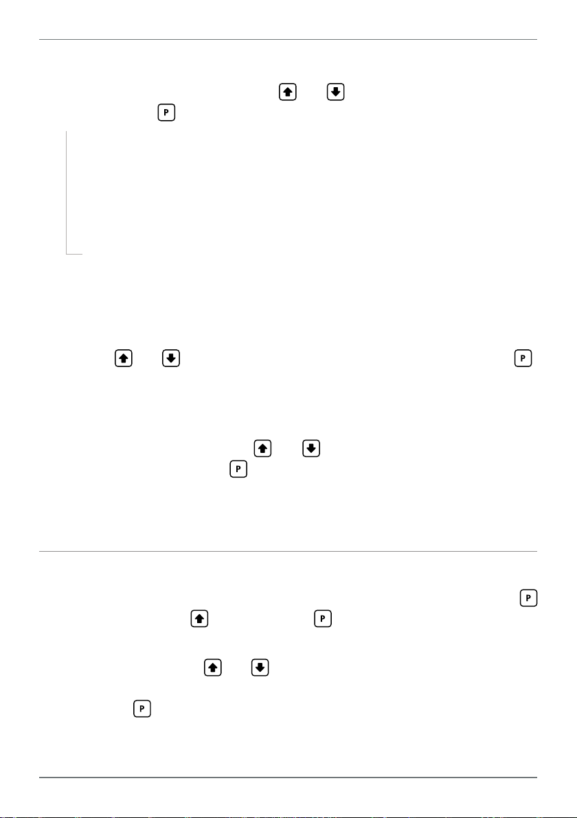
2.4 - Up and down button shortcuts
Pressing the and buttons from the main operational display allows instant
access to a number of values held in the controller's memory. These variables will ap-
pear in the order shown in the table below, and will cycle continuously at each press
of the or button. Press at any time to return to normal operating mode.
PEAK and VA LY (valley) may be reset to zero by pressing the
the same time while the variable is being displayed.
Up and Down button shortcuts:
PWR Power
AMP Current
PEAK Max. measured weight
since the unit was
turned on or reset
P.F. Power Factor
ENRG Energy (see 3.5 or 6.2F
FREQ Frequency
VLT S Voltage
VA LY (Valley) Min. measured
and buttons at
to reset)
weight since the unit
was turned on or reset
LD-UAC-MAN-19V01 (0211) Copyright © 2019 Dene Instruments
Page 6

6
Secondary
Single Phase 2-Wire (Current)
VOLTAGE
Single Phase 2-Wire (Voltage/Freq)
3
WIRING
BEFORE YOU BEGIN WIRING, ensure that the power supply is disconnected.
3.1 - Pinouts
A B
Key
3.1A Relay Output (See 3.3)
3.1B Analog Output (See 3.4)
3.1C Analog Input (See 3.2)
3.1D Function Pins (See 3.5)
D
EC
3.1E Power Supply (See 3.6)
3.2 - Wire the analog input See 3.1C
Wire the analog input as required for your application, referring to the diagrams
below.
CURRENT
INPUT
CT, 5A
LD-UAC-MAN-19V01 (0211) Copyright © 2019 Dene Instruments
INPUT
Page 7

7
Secondary
VOLTAGE
Single Phase 2-Wire (Power/P.F.)
Secondary
VOLTAGE
Single Phase 3-Wire (Power/P.F.)
SP2 SP1
SP3SP4 SP1SP2
+mA
CURRENT
INPUT
CT, 5A
INPUT
CURRENT
INPUT
CT, 5A
INPUT
3.3 - Wire the relay outputs See 3.1A
If your controller has relay outputs tted, wire them as shown below. Relays can be
programmed to operate within the total span range of the controller.
-R2
-R4
3.4 - Wire the analog output
See 3.1B
If your controller has analog output tted, wire it as shown for either
voltage (0–10V) or current (4–20mA).
-A
–V+V–mA
LD-UAC-MAN-19V01 (0211) Copyright © 2019 Dene Instruments
Page 8

8
Valley Tes tEnergy
Peak
3.5 - Wire the function pins
See 3.1D
Connect external switches to enable a function
to be executed when its switch is activated:
Valley Activating this pin will reset the Valley
value to the current display value
Energy Activating this pin will clear the
Energy value to zero
(You can also do this using the 'Energy
Pulse' feature [see 6.2F])
Tes t Activating this pin will reset the meter
Peak Activating this pin will reset the Peak value to the current display value
COM
3.6 - Wire the power supply See 3.1E
DO NOT attempt to wire your controller while the power is on. NEVER connect your
low voltage controller to mains power.
Wire your controller for low or high voltage power supply, as show in the diagrams
below. Check the label on the unit against the colour of the connector:
› Orange =
High voltage (85–265V AC,
95–370V DC)
› Black =
Low voltage (15–48V AC,
High
voltage
(HV)
+DC
Live
AC
−DC
Neutral
AC
Low
voltage
(LV)
+DC
Live
AC
10–72V DC)
HV power
supply
Once you have completed the wiring process it is safe to switch on your power
supply. Ensure that your display is functioning before you proceed.
LD-UAC-MAN-19V01 (0211) Copyright © 2019 Dene Instruments
LV power
supply
−DC
Neutral
AC
Page 9

9
120
39
155mm (6.10") minimum depth required behind panel
4
DIMENSIONS & INSTALLATION
4.1 - Case dimensions
mm (0.16")
4
96
mm
92mm
(3.78")
(3.62")
mm (4.72")
mm (1.54")
Cabling
Allowance
155mm (6.10") minimum depth required behind panel
mm
48
(1.89")
120 mm (4.72") 39mm (1.54")
mm (0.16")
4
45mm
(1.77")
Cabling
Allowance
LD-UAC-MAN-19V01 (0211) Copyright © 2019 Dene Instruments
Page 10

10
Panel Meter Faceplate
Panel Cutout
4.2 - Installation instructions
A Prepare the Panel Cutout to
92 x 45mm ±.5 (3.62 x 1.77" ±.02),
as shown below.
Allow at least 155mm (6.10")
depth behind the panel to accommodate the meter body, protruding connectors and cabling.
B Remove the Mounting Clips from
the meter back.
Panel
Gasket
Mounting
Clips
Screws
C Slide the Panel Gasket over the
rear of the unit to the back of the
Meter Faceplate.
D From the front of the panel, insert
the meter into the Panel Cutout.
Holding the unit in place, engage
the Mounting Clips so that the tabs
snap into place over the notches on
the case.
E To achieve a proper seal, tighten
the Screws evenly until the unit sits
rmly against the panel. Do not
over-tighten the screws.
92mm ±.5
(3.62″ ±.02)
45mm ±.5
(1.77″ ±.02)
LD-UAC-MAN-19V01 (0211) Copyright © 2019 Dene Instruments
Page 11

11
5
INPUT SETUP & CALIBRATION
5.1 - Enter Cal PIN number
A Enter the calibration mode by pressing the button.
_ _ _ ENTER CAL PIN NUMBER scrolls across the display and toggles with 0. Use
the
press . If the correct PIN is entered, setup is started at 5.2.
If an incorrect PIN number is entered, _ _ _ INCORRECT PIN - ACCESS DENIED
scrolls across the display and it returns to normal operating mode.
You will have the opportunity to change your PIN number at the end of this section
(5.7). If you have forgotten your PIN number, see Section 8.
and buttons to enter your security code (factory default '1'). Then
5.2 - Input setup
A _ _ _ INPUT SETUP scrolls across the display and toggles with SKIP. Press to
skip to 5.3, or use the and buttons select an input channel:
AMP (current), VLTS (voltage), PWR (power) or FREQ (frequency), and then
press to continue.
¨ If you selected PWR, continue to 5.2B now.
¨ Otherwise, skip to 5.2C now.
B _ _ _ RESOLUTION scrolls across the display. Using the
select: W, KW or MW, and then press .
Note that certain combinations of Power Resolution (5.2B) and Energy Resolution (5.3B) may
result in a scaling error. See 5.3B for more information.
C _ _ _ DECIMAL POINT scrolls across the display and toggles with the current
selection. Use the and buttons to select an option from the list:
NONE, 0.1 , 0 .12 or 0.123. Then press .
For Voltage inputs, only NONE and 0.1 are available.
For Frequency inputs, only NONE, 0.1 and 0.12 are available.
and buttons,
LD-UAC-MAN-19V01 (0211) Copyright © 2019 Dene Instruments
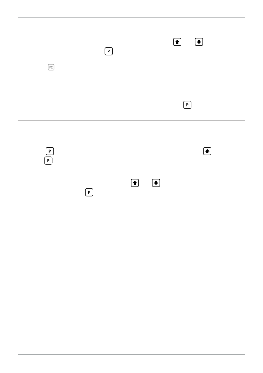
Page 12

12
Input signal in counts
Sampling
Averaging (5.2D−E)
Your controller has input sig-
Input exceeds
averaging window
nal averaging, optimising stable
measurement.
Averaging window
in displayed counts
If the change in input exceeds the
averaging window value it will not
Number
of samples
average, ensuring fast response
when there are large dierences
between readings.
D _ _ _ AVE SAMPLES scrolls across the display and toggles with the currently
selected averaging. Using the and buttons, alter the number of input
samples that the controller will average, and then press .
Increasing the number of samples will stabilise measurement, but it will also slow down response rates.
E _ _ _ AVE WINDOW scrolls across the display and toggles with the currently
selected averaging window value. Using the and buttons, alter the signal
averaging window. Then press .
If your input signal contains large noise spikes, you can increase the size of the averaging window to ensure that these are still averaged. However, increasing the window size too far will
reduce the ability of the controller to respond quickly to real changes in input signal. Setting
AVE WINDOW to 0 will give continuous averaging as per the selected averaging samples.
F _ _ _ INPUT SETUP scrolls across the display and toggles with SKIP. You are now
back at 5.2A. To edit dierent input type, follow the instructions from 5.2A–F
again. If you do not wish to edit another input type, press now to skip to 5.3.
5.3 - Energy setup
The energy function allows you to see the total amount of energy that has been
used in W/hr, kW/hr or MW/hr.
A _ _ _ ENERGY SETUP scrolls across the display and toggles with SKIP. Press
to skip to 5.4, or the button and then to ENTR (enter) energy setup.
LD-UAC-MAN-19V01 (0211) Copyright © 2019 Dene Instruments
Page 13
13
B _ _ _ RESOLUTION scrolls across the display and toggles with the currently se-
lected energy resolution. Using the and buttons, select: W, KW or MW,
and then press .
` If the resolution was set successfully, setup will proceed to 5.3C.
n _ _ _ SCALING ERROR - CHANGE ENERGY SETTINGS!
If you see this message, then the combination of settings that you have
selected in Power Resolution (5.2B) and Energy Resolution (5.3B) will
produce values which are too large for the controller to process or display.
To correct this, modify the settings in 5.2B or 5.3B.
C _ _ _ CUTOFF scrolls across the display and toggles with the currently selected
power cuto value. When the power input value falls below the cuto value,
the energy register will stop accumulating power, and will pause until the input
power is greater than or equal to the cuto value again.
Use the
and buttons to adjust this value as required, and then press .
D _ _ _ ROLL OVER scrolls across the display and toggles with the current setting.
If rollover is ON, then when the energy value exceeds 9,999, the display will roll
to 0 and continue accumulating. If rollover is OFF, then the display will read
OVER in this situation. Use the
and buttons to turn the rollover feature
OFF or ON, and then press .
Note that the ROLL OVER feature does not produce any output pulse or other indication when
it rolls over. (An output pulse can be activated on a setpoint with its data source set to Energy.
See 6.2F for more information, and to enable this feature.)
5.4 - Display setup
A _ _ _ DISPLAY SETUP scrolls across the display and toggles with SKIP. Press
to skip to 5.5, or the button and then to ENTR (enter) display setup.
B _ _ _ DISPLAY SOURCE scrolls across the display and toggles with the current
display source. Use the
age), PWR (power), FREQ (frequency), ENRG (energy) or P.F. (power factor).
Then press .
and buttons to select: AMP (current), VLTS (volt-
LD-UAC-MAN-19V01 (0211) Copyright © 2019 Dene Instruments
Page 14

14
5.5 - Calibrate
A _ _ _ CALIBRATE? scrolls across the display and toggles with SKIP. Press to
skip to 5.6, or use the and buttons to select a channel to calibrate: AMP
(current) or VLTS (voltage), and then press .
¨ If you selected VLT S, skip to 5.5C now.
¨ If you selected AMP, continue to 5.5B now.
B _ _ _ CALIBRATION TECHNIQUE scrolls across the display and toggles with the
current selection. Use the
AUTO, MAN (manual), or CT (current transformer), and press to continue.
¨ If you selected AUTO, complete steps 5.5C–E now.
¨ If you selected MAN, complete step 5.5F now.
¨ If you selected CT, complete steps 5.5G−H now.
AUTO (Automatic) - Calibrate by applying high and low input signals.
MAN (Manual) - Calibrate by entering the required display value at full scale.
CT (Current Transformer) - Calibrate by specifying the input and output current for the C.T.
and buttons to select a calibration method:
Auto calibration
C _ _ _ APPLY LOW SCALE INPUT – – – –ENTER LOW DISPLAY VALUE scrolls
across and toggles with the current selection. Apply the required low input sig-
nal. Then, using the
and buttons, enter your low display value. Press
to accept and continue.
D _ _ _ APPLY HIGH SCALE INPUT – – – –ENTER HIGH DISPLAY VALUE scrolls
across and toggles with the current selection. Apply the required high input
signal. Then, using the
and buttons, enter your high display value, and
press .
E If Auto calibration was successful, you will be directed out of the calibration
menu to the operational display without viewing any further scrolling messag-
es. (To proceed to step 5.6, you must select SKIP at 5.5A.)
If calibration fails, _ _ _ CALIBRATION FAILED will scroll across the display and
you will be directed back to the operational display. The most likely cause of this
LD-UAC-MAN-19V01 (0211) Copyright © 2019 Dene Instruments
Page 15

15
error is that the controller could not detect any change in input signal during
calibration. Check your signal and connections, and repeat the procedure.
Manual calibration
F _ _ _ ENTER DISPLAY VALUE AT FULL SCALE CURRENT scrolls across the dis-
play and toggles with the current selection. Use the
and buttons to enter
a display value for the full scale current input (typically 5A). Then press .
Manual calibration is now complete. You will be directed back to the opera-
tional display. (To proceed to step 5.6, you must select SKIP at 5.5A.)
Current Transformer calibration
G _ _ _ ENTER CT INPUT CURRENT scrolls across the display and toggles with the
currently selected CT input value. Adjust this value using the
and but-
tons, and then press .
H _ _ _ ENTER CT OUTPUT CURRENT scrolls across the display and toggles with
the currently selected CT output value. Adjust this value using the
and
buttons, and then press .
CT calibration is now complete. You will be directed back to the operational
display. (To proceed to step 5.6, you must select SKIP at 5.5A.)
5.6 - Analog output setup
N.B. All new units are calibrated before shipping. Recalibration is only necessary if settings
are wiped or the unit's accuracy requires verication aer a long period of use. e.g. 1 year.
A _ _ _ ANALOG OUTPUT SETUP scrolls across the display and toggles with SKIP.
If your controller does not have analog output installed, (or you do not wish to
congure your analog output now), press to skip to 5.7. Otherwise, press
the button and then to ENTER analog output setup.
B _ _ _ DATA SOURCE scrolls across the display and toggles with the current analog
output data source. Use the
rent), VLT S (voltage), PWR (power), FREQ (frequency), ENRG (energy), or P.F.
and buttons to select an option: AMP (cur-
LD-UAC-MAN-19V01 (0211) Copyright © 2019 Dene Instruments
Page 16

16
(power factor). Then press .
C _ _ _ LOW SCALE VALUE scrolls across the display and toggles with the cur-
rently selected low scale display value. Use the
cal low position, and then press .
D _ _ _ HIGH SCALE VALUE scrolls across the display and toggles with the cur-
rently selected high scale display value. Use the
cal high position, and then press .
E _ _ _ CALIBRATE ANALOG O/P? scrolls across the display and toggles with NO.
Use the
Factory analog output calibration is precisely set before shipping this instru-
ment, and should not be adjusted unless advised by the manufacturer.
F _ _ _ CAL LOW ANALOG O/P scrolls across and toggles with a calibration num-
ber shown in internal units (around -16000). Press the
your multimeter displays your target low output (e.g. 4mA), then press .
and buttons to select YES or NO, and then press .
¨ If you selected YES, connect a mA or volt meter across the analog output
connector (see 3.1B), and then continue to 5.6F.
¨ If you selected NO, the display will return to normal operating mode.
and buttons to enter your
and buttons to enter your
and buttons until
G _ _ _ CAL HIGH ANALOG OUTPUT scrolls across and toggles with a calibration
number shown in internal units (around 30000). Press the
until your multimeter displays your target high output, then press .
Analog output calibration is now complete. The display will return to normal
operating mode.
and buttons
5.7 - Edit Cal PIN number
A _ _ _ EDIT CAL PIN NUMBER scrolls across the display and toggles with SKIP.
Press to skip and return to the operational display, or the button and
then to ENTER and change your PIN number.
B _ _ _ ENTER NEW CAL PIN NUMBER scrolls across the display and toggles with
the current PIN (default 1). Using the
bration PIN number. Then press to exit to the operational display.
LD-UAC-MAN-19V01 (0211) Copyright © 2019 Dene Instruments
and buttons, enter your new Cali-
Page 17

17
6
The soware in your controller will allow you to congure up to 4 setpoints,
however full functionality is only supported when relay output hardware installed.
(Setpoints with no corresponding relay output hardware may be used as simple LED
indicators, if desired. In this case, features requiring relay output functionality will
continue to appear in the setup menu, but will be ignored by the controller.)
SETPOINT SETUP
6.1 - Enter Setpoint PIN number
A Enter setpoint setup mode by pressing and holding the button for 3 seconds.
_ _ _ ENTER SP PIN NUMBER scrolls across the display and toggles with 0.
Use the
Then press . If the correct PIN is entered, setup is started at 6.2.
If an incorrect PIN number is entered, _ _ _ INCORRECT PIN NUMBER - ACCESS
DENIED scrolls across the display and it returns to normal operating mode.
You will have the opportunity to change your PIN number at the end of this section
(6.3). If you have forgotten your PIN number, see Section 8.
and buttons to enter your security code (factory default '1').
6.2 - Setpoint setup
A _ _ _ EDIT SETPOINT scrolls across the display and toggles with SKIP. Press
now to skip to 6.3, or use the and buttons to select a setpoint to edit,
and then press .
B _ _ _ SP VALUE scrolls across the display and toggles with the current value for
the selected setpoint. Using the
which the selected setpoint will activate, and then press .
and buttons, adjust the display value at
LD-UAC-MAN-19V01 (0211) Copyright © 2019 Dene Instruments
Page 18

18
C The step that you proceed to now will depend on which setpoint you are editing
(selected in 6.2A):
¨ If you are currently editing SP 1, skip to 6.2E now.
¨ If you are currently editing SP 2–4, continue to 6.2D now.
D _ _ _ TRACK SP1 scrolls across the display and toggles with the tracking setting
for the selected setpoint. A setpoint with TRACK SP1 enabled will inherit the
SP Source (6.2E) of SP 1, and track the SP Value of SP 1. (The setpoint value of
the tracking setpoint will eectively become an oset value.)
Using the
and buttons, turn tracking OFF or ON, and then press .
¨ If you selected ON, then the step that you proceed to now will depend on
the SP Source (6.2E) that is currently set for SP 1:
` If the SP Source for SP 1 is set to ENRG, skip to 6.2F now.
` Otherwise, skip to 6.2H now.
¨ If you selected OFF, continue to 6.2E now.
E _ _ _ SP SOURCE scrolls across the display and toggles with the activation source
for the selected setpoint. Use the
and buttons to select from the follow-
ing options: AMP (current), VLTS (voltage), PWR (power), FREQ (frequency),
ENRG (energy), or P.F. (power factor). Then press .
¨ If you selected ENRG, continue to 6.2F now.
¨ Otherwise, skip to 6.2H now.
Energy Setpoints
(For setpoints with SP SOURCE set to ENRG, or setpoints that inherit ENRG data source from
tracking SP 1.)
F _ _ _ ENERGY PULSE scrolls across the display and toggles with the current set-
ting. If this feature is enabled, then when the setpoint is activated it will output
a pulse and then clear the Energy value to zero. Using the and buttons,
turn the energy pulse feature OFF or ON, and then press .
¨ If you selected ON, continue to 6.2G now.
¨ Otherwise, skip to 6.2H now.
LD-UAC-MAN-19V01 (0211) Copyright © 2019 Dene Instruments
Page 19

19
Energised Above
Energised Above
G _ _ _ PULSE WIDTH scrolls across the display and toggles with the current pulse
width. Use the and buttons to adjust the pulse width from 0.1 to 10
seconds, and then press .
¨ Please skip steps 6.2H−K, and proceed to 6.2L now.
Current, Voltage, Power, Frequency, or Power Factor Setpoints
H _ _ _ SP ACTIVATION scrolls across the display and toggles with the current
activation for the selected setpoint. Using the
and buttons, select the
relay activation to operate ABVE (above) or BLW (below) the setpoint value,
and then press .
ABVE: Relay turns on above the setpoint value and o below it.
BLW: Relay turns on below the setpoint value and o above it.
I _ _ _ SP TYPE scrolls across the display and toggles with the current setting for
the selected setpoint. Using the and buttons, select either ALM (alarm)
or CTRL (control), and then press .
ALM - SETPOINT VALUE controls setpoint
activation point. HYSTERESIS VALUE con-
trols setpoint deactivation point.
CTRL - SETPOINT VALUE controls setpoint
deactivation point. HYSTERESIS VALUE con-
trols setpoint reactivation point.
Hysteresis
band
Hysteresis
band
Energised Below
Hysteresis
band
Hysteresis
band
Energised Below
J _ _ _ HYSTERESIS VALUE scrolls across the display and toggles with the hyster-
esis value for the selected setpoint. Use the and buttons to adjust this
value if required, and then press .
The HYSTERESIS VALUE denes the separation band between setpoint activation and deacti-
vation, and will operate as per the SP TYPE setting selected in 6.2I.
K _ _ _ MAKE DELAY scrolls across the display and toggles with the current make
delay time for the selected setpoint. This is the time delay between setpoint ac-
tivation, and when the relay turns on. Adjust this value in 0.1 second increments
using the and buttons, and then press .
LD-UAC-MAN-19V01 (0211) Copyright © 2019 Dene Instruments
Page 20
20
L _ _ _ USER ACCESS? scrolls across the display and toggles with the direct access
permission setting for the selected setpoint. Use the and to select either
OFF or ON, and then press .
When enabled, this option allows the selected setpoint's value to be edited directly aer pressing the button, without needing to enter a PIN number or go through all of the other options. Each setpoint can individually have this option enabled or disabled. See Section 7.
M _ _ _ EDIT SETPOINT scrolls across the display and toggles with SKIP. You are
now back at 6.2A. To edit another setpoint, follow the instructions from 6.2A–M
again. If you do not wish to edit another setpoint, press now to skip to 6.3.
6.3 - Edit SP PIN number
A _ _ _ EDIT SP PIN NUMBER scrolls across the display and toggles with SKIP.
Press to skip and return to the operational display, or the button and
then to ENTER and change your PIN number.
B _ _ _ ENTER NEW SP PIN NUMBER scrolls across the display and toggles with
the current PIN (default 1). Using the
number. Then press to exit to the operational display.
and buttons, enter your new SP PIN
LD-UAC-MAN-19V01 (0211) Copyright © 2019 Dene Instruments
Page 21

21
7
If none of the setpoints have their direct access option enabled then this feature will
be disabled and the
A Begin by pressing the
B The name of the rst access-enabled setpoint will appear on the display and
toggle with the current value for that setpoint. Using the
adjust the selected value. Then press to accept and continue.
C The name of the next access-enabled setpoint will appear on the display, along
with its setpoint value. Repeat step 7B. The direct access menu will proceed
through all access-enabled setpoints in this fashion. Pressing
bled setpoint will exit and return to the operational display.
8
SETPOINT DIRECT ACCESS
button will not respond to a short button press. (See 6.2L.)
button for less than 3 seconds.
and buttons,
for the last ena-
RESET PIN NUMBERS / VIEW FIRMWARE VERSION
If you have forgotten your PIN number(s), follow the procedure below to reset both
the Calibration and Setpoint PINs to their factory default of 1.
This procedure will also allow you to view the current soware installed on your
device, which may be required for support purposes.
A Press
execute and you may need several tries to get it right.)
B A message will appear on the display, with details of the unit's current soware
conguration (Product name, Firmware Version, and Macro Version). At the
end, you will see _ _ _ ALL PIN NUMBERS RESET TO 1.
C Both the Cal PIN number and the SP PIN number have now been reset to '1'.
You can change this, if required, by following the instructions in 5.7 (for Cal)
and 6.3 (for SP), using '1' to enter each menu initially.
, and at the same time. (This key combination can be dicult to
LD-UAC-MAN-19V01 (0211) Copyright © 2019 Dene Instruments
Page 22

22
LD-UAC-MAN-19V01 (0211) Copyright © 2019 Dene Instruments
Page 23

23
LD-UAC-MAN-19V01 (0211) Copyright © 2019 Dene Instruments
Page 24

De ne Instruments
New Zealand
(Head O ce)
Auckland 0632, New Zealand
Auckland 0661, New Zealand
Ph
Fax
www.de neinstruments.co.nz
10B Vega Place, Rosedale,
PO Box 245 Westpark Village,
: +64 (9) 835 1550
: +64 (9) 835 1250
sales@de neinstruments.co.nz
LD-UAC MV1.2 Document Revision Code: LD-UAC-MAN-15V02 Date Code: 150826
United States (Dallas, TX)
Ph: (214) 926 4950
sales@de neinstruments.com
www.de neinstruments.com
 Loading...