

Page 1
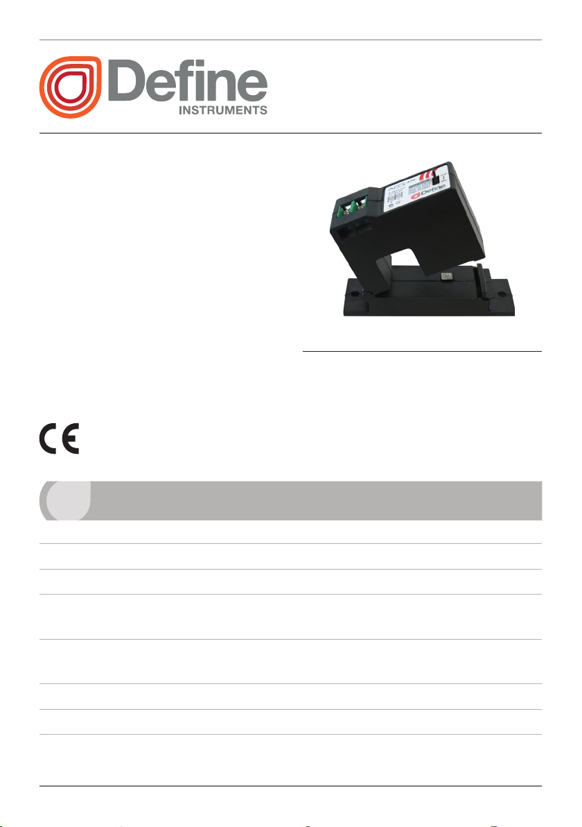
The ACCS-420 split core current transmitter converts an AC current signal into
an industry standard 4–20mA signal.
It offers a low cost alternative for
measuring power and monitoring the
operation of fans, pumps, and other
equipment.
› Split core allows easy installation
without disconnecting cables
› Three jumper selectable ranges, for
measuring up to 200A
› 4–20mA loop powered output
1
ACCS-420(-L)
AC Current Sensor
Contents
1 - Specications ............................... 1
2 - Installation & Setup ..................... 2
3 - Troubleshooting ........................... 4
1
Sensor type Current transformer
AC to DC conversion technique Averaging scaled in RMS
Header selectable amperage range ACCS-420: 100/150/200A,
ACCS-420-L: 10/20/50A
Overload (continuous) ACCS-420: 100A= 175A, 150A= 300A, 200A= 400A
ACCS-420-L: 10A= 80A, 20A= 120A, 50A= 200A
Output
Power supply 15–36V DC
Accuracy 1% of full scale
SPECIFICATIONS
4–20mA loop powered
, representing 0–100% of full scale input range
ACCS-420-MAN-15V04 (0630)Copyright © 2015 Dene Instruments Ltd
Page 2

2
Operating temperature –10 to 50°C (14 to 122°F)
Operating humidity 10–90% (non-condensing)
Response time 250ms (10–90%)
Isolation voltage 2000V
Frequency 50–60Hz
Casing Split core hinged type, screw mounting case, ABS material
Dimensions (H x W x D) 66 x 100 x 32mm (2.6 x 3.9 x 1.3")
2
INSTALLATION & SETUP
RISK OF SHOCK!
DISCONNECT POWER SUPPLY BEFORE MAKING
ELECTRICAL CONNECTIONS.
Contact with components carrying hazardous voltage can cause electrical shock
and may result in severe personal injury or death.
2.1 - Installation
Run the wire that you wish to monitor through the hole in the sensor.
› Press the tab toward the sensor to open.
› After placing the wire in the opening, press the hinged portion down firmly
until a definite click is heard and the tab pops out fully.
› The sensor can be mounted using screw holes in any position, or hung directly
on wires with wire ties.
Keep split core sensors clean. Be careful not to allow grit or dirt to build up on
contacts. Operation can be impaired if the mating surfaces do not have a connection.
Always check visually before closing.
ACCS-420-MAN-15V04 (0630) Copyright © 2015 Dene Instruments Ltd
Page 3

3
Jump Range
200A
ACCS-420:
ACCS-420-L:
2.2 - Output wiring
Connect the 4–20mA control or monitoring wires to the sensor using 14 to 22
AWG copper wire.
› Tighten the terminals securely.
› Be sure the output load or loop
requirements are met.
› The 4–20mA signal cable must be
screened, with the screened earth
at one end only.
2.3 - Range selection
Select the correct range by placing the
jumper in the appropriate position.
› Determine the normal operating
amperage of the monitored circuit.
› Select the range that is equal to
or slightly higher than the normal
operating amperage.
24V DC
Power Supply
0–100A
0–10A
Analogue
Input
0–150A
0–20A
0–
0–50A
2.4 - Usage notes
The ACCS-420 is intended to provide a 4–20mA input to monitoring equipment under normal operating conditions.
Where failure or malfunction of the ACCS-420 could lead to personal injury or
damage to control equipment or other property, additional precautions must be
designed into the control system. Incorporate and maintain other devices such as
supervisory or alarm systems, or safety or limit controls intended to warn of, or protect against, failure or malfunction of the ACCS-420.
ACCS-420-MAN-15V04 (0630)Copyright © 2015 Dene Instruments Ltd
Page 4

4
2.5 - Maintenance
Upon nal inspection of the ACCS-420, no routine maintenance is required. A periodic check of system calibration is recommended.
The ACCS-420 is not eld serviceable and should be returned if faulty. Field repair
should not be attempted and will void warranty.
3
TROUBLESHOOTING
Sensor has no output › The polarity may not be properly matched. Check and cor-
rect wiring polarity.
› The monitored load may be either not AC, or not on. Check
that the monitored AC load is on.
› Check the power supply current and voltage rating.
Output signal is too low › The jumper may be set in a range that is too high for the cur-
rent being monitored. Move the jumper to the correct range.
› The monitored current may be below the minimal current
required. Loop the monitored wire several times through the
opening until the sensed current rises above the minimum.
Sensed Amps = Actual Amps x Number of Loops. Count the
loops on the inside of the opening.
› The load current must be sinusoidal.
Sensor is always at 4mA › The monitored load may be either not AC, or not on. Check
that the monitored AC load is on.
Output signal is always
at maximum (20mA)
› The jumper may be set in a range that is too low for the cur-
rent being monitored. Move the jumper to the correct range.
New Zealand (Head Oce)
Ph: +64 (9) 835-1550
Aus: 1800 810-820
rolla@deneinstruments.com
www.deneinstruments.com
ACCS-420(-L) Document Revision Code: ACCS-420-MAN-15V04 Date Code: 150630
South Africa (Johannesburg)
Ph: 011 792 1210
charlene@deneinstruments.co.za
dylan.swartz@deneinstruments.co.za
www.deneinstruments.co.za
 Loading...