

Defiant MST18920lwdf Use And Care Manual
THANK YOU
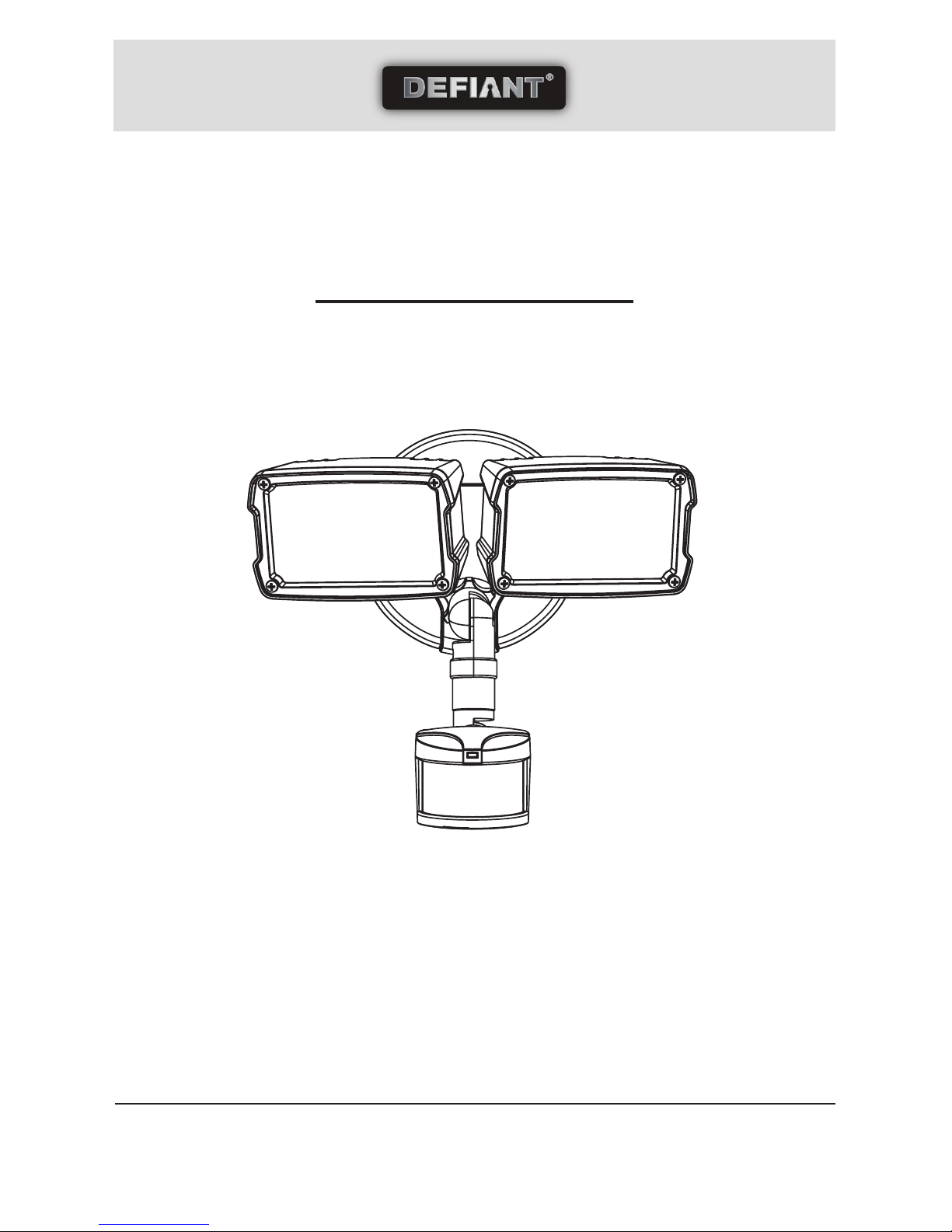
We appreciate the trust and confidence you have placed in Defiant® through the purchase of this motion activated
LED floodlight. We strive to continually create quality products designed to enhance your home. Visit us online to see
our full line of products available for your home improvement needs. Thank you for choosing Defiant®!
USE AND CARE GUIDE
Questions, problems, missing parts? Before returning to the store call
Defiant® Customer Service
8 a.m. - 6 p.m., EST, Monday-Friday
1-866-308-3976
HOmedepOT.cOm
180° MOTION ACTIVATED LED FLOODLIGHT
Item #625-057
Model #MST18920LWDF
2
Table of Contents
Table of Contents ......................................2
Safety Information ....................................2
Warranty ...................................................3
Pre-Installation .........................................4
Installation ................................................7
Operation...................................................8
Feature Selection ......................................9
Troubleshooting ........................................9
Safety Information
WARNING
□ Risk of fire/electric shock. If not qualified, consult an electrician.
□ Disconnect power at fuse or circuit breaker before installing or servicing.
CAUTION
□ Connect fixture to a 120-volt, 60 Hz power source. (Any other connection voids warranty.)
□ Fixture should be installed by persons with experience in household wiring or by a qualified electrician. The
electrical system and the method of electrically connecting this fixture to it must be in accordance with the
National Electrical Code and local building codes.
□ Mount fixture to a grounded, recessed-mounted standard junction box marked for use in wet locations.
□ Suitable for wall mount or eave mounting only. Not suitable for ground mount installation.
□ For proper operation and protection against damage, the motion sensor head adjustment knobs must be
facing the ground.
□ Do not mount below 5 feet.
□ MINIMUM 75°C SUPPLY CONDUCTORS.
□ This device complies with Part 15 of the FCC Rules. Operation is subject to the following two conditions:
(1) This device may not cause harmful interference, and (2) this device must accept any interference received,
including interference that may cause undesired operation. Under Part 15 of the FCC Rules, any changes or
modifications to the motion detector described in this instruction sheet that are not expressly approved by
Cooper Lighting, LLC could void the user’s authority to operate the equipment.
NOTE: This equipment has been tested and found to comply with the limits for a Class B digital device,
pursuant to Part 15 of the FCC Rules. These limits are designed to provide reasonable protection against
harmful interference in a residential installation. This equipment generates, uses and can radiate radio
frequency energy and if not installed and used in accordance with the instructions, may cause harmful
interference to radio communications. However, there is no guarantee that interference will not occur in a
particular installation. If this equipment does cause harmful interference to radio or television reception,
which can be determined by turning the equipment off and on, the user is encouraged to try to correct the
interference by one or more of the following measures:
- Reorient or relocate the receiving antenna.
- Increase the separation between the equipment and receiver.
- Connect the equipment into an outlet on a circuit different from that to which the receiver is connected.
- Consult the dealer or an experienced radio/TV technician for help.
WARNING: FCC Regulations state that any unauthorized changes or modifications to this equipment not
expressly approved by the manufacturer could void the user’s authorization to operate this equipment.

3 HOMEDEPOT.com
Please contact 1-866-308-3976 for further assistance.
Safety Information (continued)
IMPORTANT SAFETY INFORMATION
When using product, basic precautions should always be followed, including the following:
□ Read and follow these instructions.
□ Heed all warnings, including below warnings AND those included on product.
□ Save these instructions and warnings.
□ For outdoor use only.
□ cULus LISTED for wet location.
□ Disassembling your fixture will void the warranty.
□ Your fixture is prewired and preassembled for easy installation.
Warranty
The following warranty is exclusive and in lieu of all other warranties, whether express, implied or statutory
incluiding, but not limited to, any warranty of merchantability or fitness for any particular purpose.
Cooper Lighting, LLC (“Cooper Lighting”) warrants to customers that, for a period of two years from the date of
purchase, Cooper Lighting’s products will be free from defects in materials and workmanship. The obligation of
Cooper Lighting under this warranty is expressly limited to the provision of replacement products. This warranty
is extended only to the original purchaser of the product. A purchaser’s receipt or other proof of date of original
purchase acceptable to Cooper Lighting. This is required before warranty performance shall be rendered.
This warranty does not apply to Cooper Lighting products that have been altered or repaired or that have been
subjected to neglect, abuse, misuse or accident (including shipping damages). This warranty does not apply to
products not manufactured by Cooper Lighting which have been supplied, installed, and/or used in conjunction
with Cooper Lighting products. Damage to the product caused by replacement bulbs or corrosion or discoloration
of brass components are not covered by this warranty.
Limitation of liability: In no event shall Cooper Lighting be liable for special, indirect, incidental, or consequential
damages (regardless of the form of action, whether in contract, strict liability, or in tort including negligence), nor
for lost profits; nor shall the liability of Cooper Lighting for any claims or damage arising out of or connected with
these terms or the manufacture, sale, delivery, use, maintenance, repair or modification of Cooper Lighting products,
or supply of any replacement parts therefore, exceed the purchase price of cooper Lighting products giving rise to a
claim. No labor charges will be accepted to remove or install fixtures.
Contact the Customer Service Team at 1-866-308-3976 or visit www.HomeDepot.com.
4
Wall mount
position
Eave mount
position
Before beginning assembly of product, make sure all
parts are present. Compare parts with package contents
list and hardware contents. If any part is missing
or damaged, do not attempt to assemble the product.
Estimated Assembly Time: 30 minutes
Note: Fixture should be installed by persons
with experience in household wiring or by a qualified
electrician. The electrical system and the method of
electrically connecting this fixture to it must be in
accordance with the National Electrical Code and
local building codes.
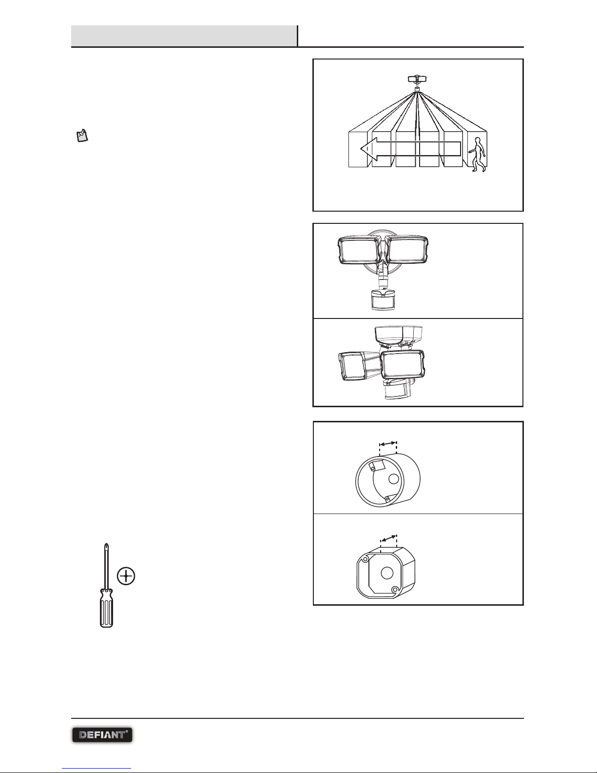
□ Install the motion sensor 8–12 feet above
the ground. Motion sensor is less sensitive
above 12 feet.
□ Locate motion sensor so motion moves across
detection zone.
□ Locate sensor away from heat producing sources
to prevent false triggering. Also be very careful not
to include objects such as windows, white walls
and water in the detection zone.
□ Locate fixture away from moving objects such as
trees and street traffic.
□ Do not install more than one motion-activated
floodlight on one wall switch.
□ Fixture can be wall or eave mounted.
□ Coverplate mounts to recessed mounted standard
junction boxes. Junction box must be at least
1-1/2 inch in depth for proper installation for
recessed mount application.
REQUIRED ITEM (SOLD SEPARATELY):
□ Clear weatherproof silicone caulk
TOOLS REQUIRED
Philips
screwdriver
Sensor detects motion that moves
across the detection zone.
Pre-Installation
Round
junction box
Octagonal
junction box
1-1/2 in.
1-1/2 in.
5 HOMEDEPOT.com
Please contact 1-866-308-3976 for further assistance.
Pre-Installation (continued)
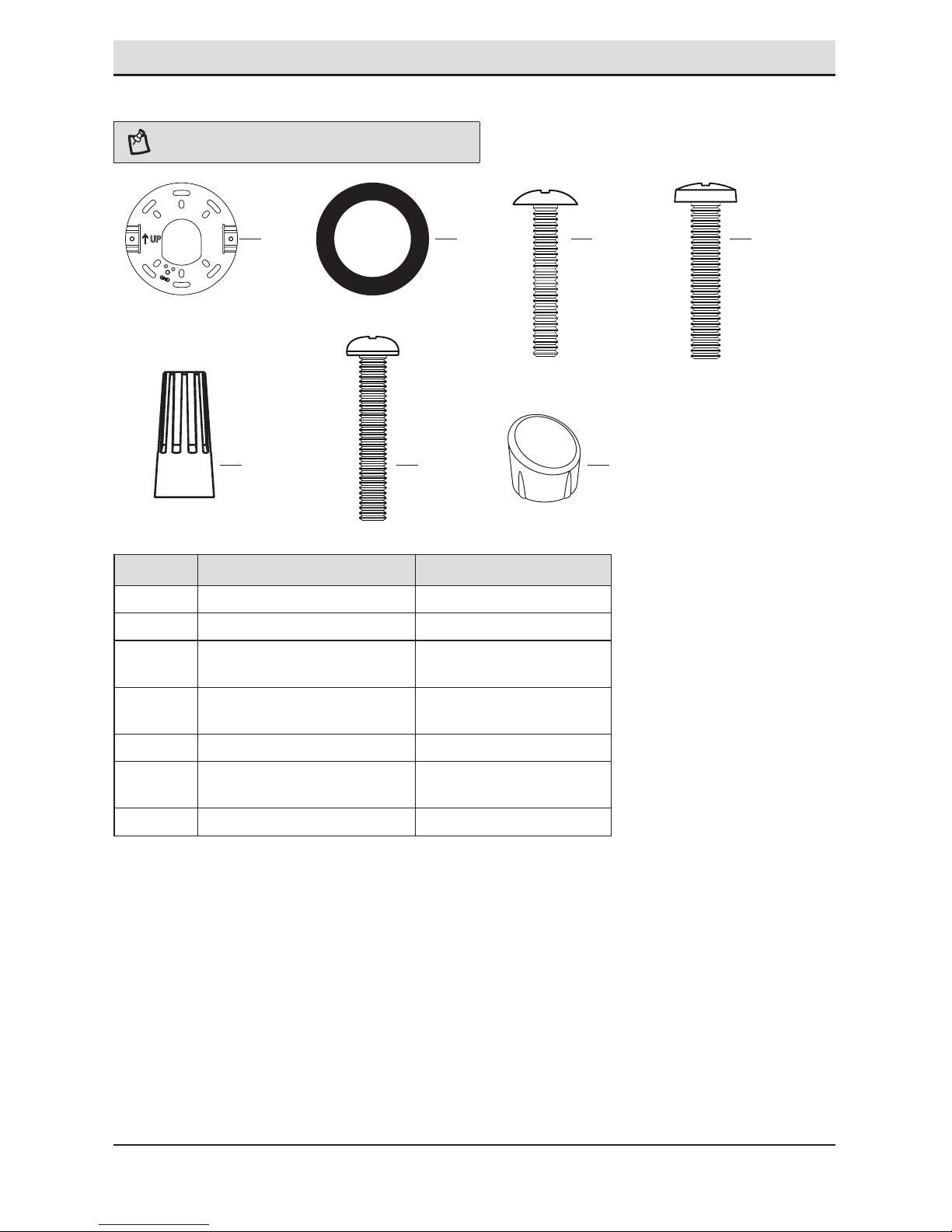
HARDWARE INCLUDED
NOTE: Hardware shown to actual size.
Part Description Quantity
AA Mounting bracket (not to scale) 1
BB Gasket (not to scale) 1
CC #6-32 x 3/4 in. junction
box screw
2
DD #8-32 x 3/4 in. junction
box screw
2
EE Wire nut 3
FF #8-32 x 1-1/4 in. cover
mounting screw
2
GG Decorative screw cap cover 2
AA BB CC DD
EE FF GG
6
Pre-Installation (continued)
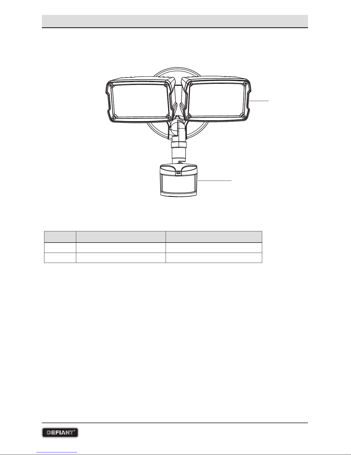
PACKAGING CONTENTS
Part Description Quantity
A Light fixture 1
B Motion sensor 1
A
B
7 HOMEDEPOT.com
Please contact 1-866-308-3976 for further assistance.
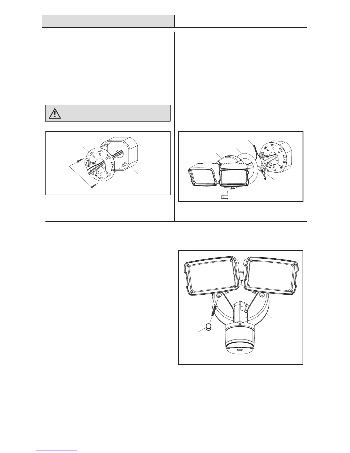
1
Mounting the coverplate
□ Line up the holes on the mounting bracket
(AA) with the holes on your junction box. Using
either (2) #6 screws (CC) or (2) #8 screws
(DD) (depending on size of the holes in your
junction box), attach the mounting bracket
(AA) to your junction box.
WARNING: Risk of electric shock. Disconnect power at
fuse or circuit breaker before installing or servicing.
2
AA
Junction
box
CC
or
DD
Wiring the fixture
□ Thread fixture wires through coverplate
gasket (BB).
□ Connect fixture black wire to house black wire
and fixture white wire to house white wire
using wire nuts (EE) provided.
□ Connect house ground wire and fixture ground
wire to the mounting bracket (AA) using the
green ground screw on the mounting bracket.
3
Mounting the fixture
□ Attach fixture (A) to the mounting bracket (AA)
using (2) #8 x 1-1/4 in. screws (FF) provided.
Be sure no loose wires remain sticking out
from underneath the coverplate. Insert the
decorative screw cover caps (GG) into the
screw holes on the coverplate for a finished
appearance.
□ Apply silicone caulk around the edges of the
coverplate to provide a watertight seal from
rain and moisture.
□ Turn on power at the main fuse/breaker box.
A
GG
FF
EE
BB
A
EE
Installation
 Loading...