

Defiant FROG-5000 Quick Start Manual
1
FROG-5000TM Quick Start Guide
Important!
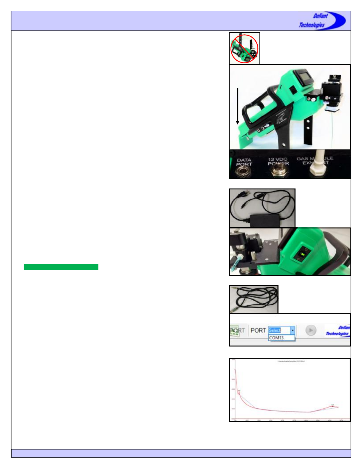
DO NOT invert the instrument with the sparge bottle attached.
DO NOT transport or store the instrument with liquid in the sparge bottle.
DO NOT handle or carry system when sample is being analyzed.
Powering the FROG
The FROG may be run on battery or an AC power source.
Battery:
1. The battery is already installed in the FROG.
2. There is a battery indicator on the back of the FROG. Five bars show that the FROG
is fully charged.
AC Power Source:
1. The FROG can be run on an AC Power Source. To run on power, plug power supply
(Figure 3) into power source and then into 12 VDC Power port on side of FROG
(Figure 2).
To turn the FROG on, slide the power switch located on the side of the instrument into
the up position. A green light should appear (Figure 4).
Installing the Ellvin GC Software
The Ellvin GC Software is located on a USB Drive in the zipper pouch of the FROG’s
case. To install the software run the setup file located in the folder labeled Defiant Tech
Ellvin.
Recommended Computer Specifications: Pentium dual core or faster, Windows 7 or
more current, and 2 GB memory.
Figure 1: Do not invert FROG with sparge
bottle attached.
Battery
Indicator
Here
Figure 2: FROG-5000 and close up of data and power ports
Figure 3: Power Cable
Connecting The FROG to Ellvin
1. Open the Ellvin GC Software
2. Plug serial data cable (Figure 5) into data port on side of FROG (Figure 2).
3. Turn FROG on
4. In Ellvin select the dropdown menu to the right of the port icon (Figure 6) and
select a COM port (the FROG is usually the last port on the list).
5. If connection is successful in the lower left corner of the software it will display:
CONNECTED PARAMS LOADED
6. If a connection was unsuccessful it may be necessary to install the proper drivers.
These can be installed manually by opening the CDM application on the software
USB drive under Defiant Tech Ellvin\USB to Serial Drivers\ CDM 2.04.06.exe.
Setting up the FROG for Sampling
Water/Soil Sampling will require:
Sparge Tube and 5 mL Syringe. For blank water samples use distilled or de-ionized
water.
Air Sampling will require:
FROG Air Sampling Kit (pg 6). For blank air samples the carbon filter tube in the air
sampling kit can be used to filter the air or any other source of clean air may be used.
Refer to the following pages for further details: Water Analysis page 4, Soil Analysis
page 5, Air Analysis pages 6 and 7.
Before sampling:
1. Make sure instrument settings are correct for the application
2. Calibrate or have the Frog calibrated for the application
3. Run a blank before attempting sample analysis. A blank run should produce a clean
baseline (Figure 7)
4. (Optional) Adjust Retention Times if using the Frog at a different location than the
one where it was calibrated. Elevation changes will affect retention times.
Home
Figure 4: Power switch (on position)
Figure 5: Serial Data Cable
Figure 6: Selecting a COM port to connect FROG to software
Figure 7: Clean baseline in Ellvin, free of peaks (Note: there
is a slight peak in the beginning, this is normal and acceptable)
www.defiant-tech.com
2
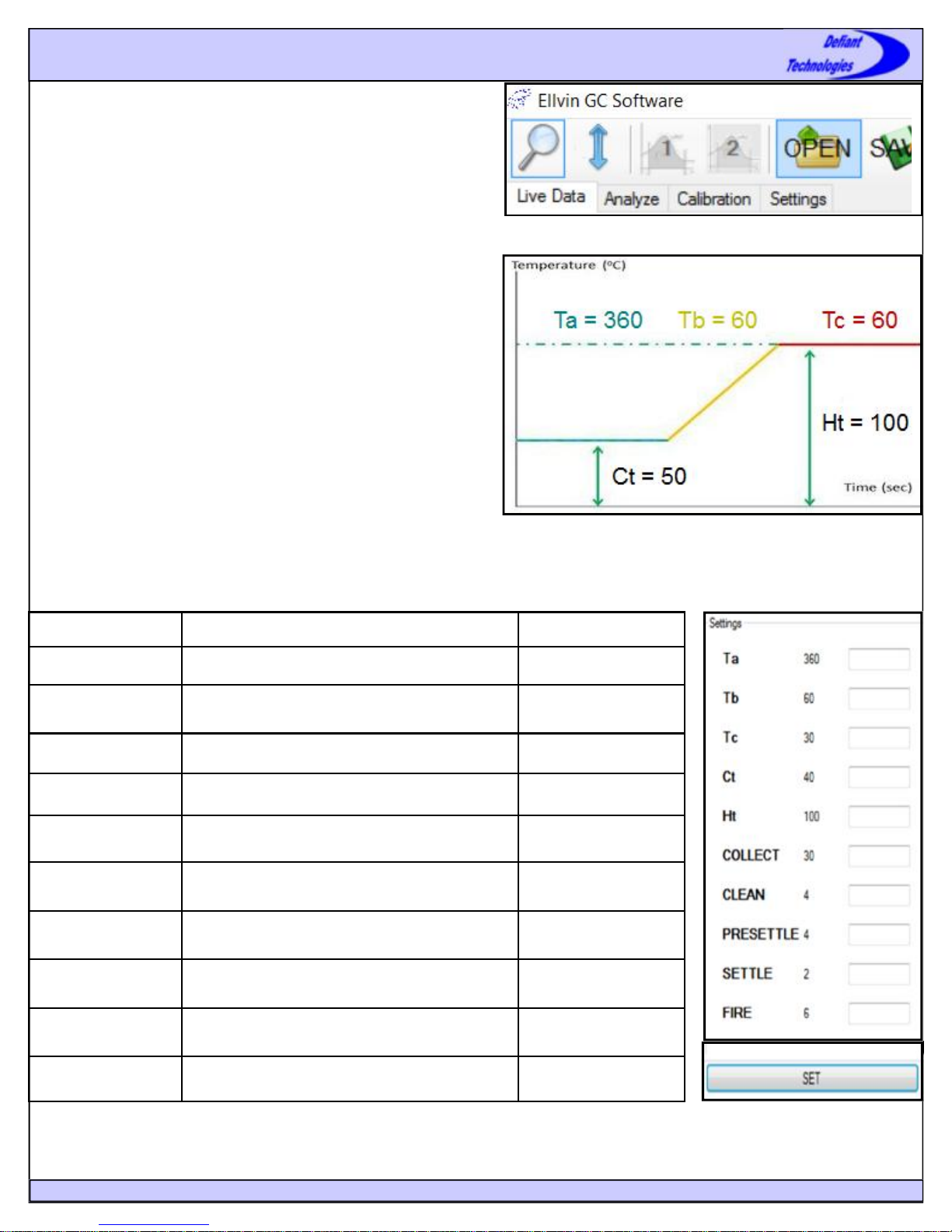
Software Tabs
In the Ellvin GC Software there are four different windows that are
accessed with tabs at the top left of the screen (Figure 8). Each tab is used
for the following:
• Live Data: live viewing of a Frog sample run with the Frog connected
to the software
• Analysis Tab: analysis of completed instrument runs
• Calibration Tab: creating, loading or viewing a calibration file
• Settings Tab: viewing or modifying instrument settings.
Software Tabs and Instrument Settings
Setting the Frog up for an Application
It is important to make sure the Frog is using the correct settings for an
application. If the Frog was calibrated by Defiant or another company the
settings have already been established and set for you.
The settings define temperature and duration parameters for various phases
of the instrument’s analysis cycle. The settings for optimal instrument
performance depend on the target analyte and should be set accordingly.
Figure 9 diagrams the settings described in Figure 10.
Changing Instrument Settings
1. With the Frog connected to the software, in the settings tab, locate
the settings box you like to modify (Figure 11).
2. In the empty box to the right of the setting: Enter a non-zero integer
then click SET to apply the settings to the instrument.
Note: Changes to the settings are stored on the instrument and DO NOT
revert to the default settings when power is removed or computer is
disconnected.
Figure 8: Tabs in Software
Figure 9: Diagram of FROG Instrument Settings.
Settings Description Setting Range
Ta Hold time at lower GC temperature (seconds) 2-900 (seconds)
Tb
Tc Hold time at hot GC temperature (seconds) 2-900 (seconds)
Ct Initial cold GC temperature (oC) 1-99 (oC)
Ht Final hot GC temperature (oC) 30-300 (oC)
COLLECT Collection time of analytes onto PC (seconds) 10-900 (seconds)
CLEAN Time cleaning PC by heating (seconds) 2-10 (seconds)
PRESETTLE Time PC cools after cleaning (seconds) 2-20 (seconds)
SETTLE
FIRE Time PC is heated to release analytes (seconds) 2-10 (seconds)
Ramp time from GC cold to GC hot temperature
(seconds)
Time allowed for pressure to stabilize before PC
FIRE (seconds)
2-900 (seconds)
2-20 (seconds)
Figure 10: Settings Descriptions
Home
Figure 11: Table of current instrument
settings, with adjustment boxes.
www.defiant-tech.com
3
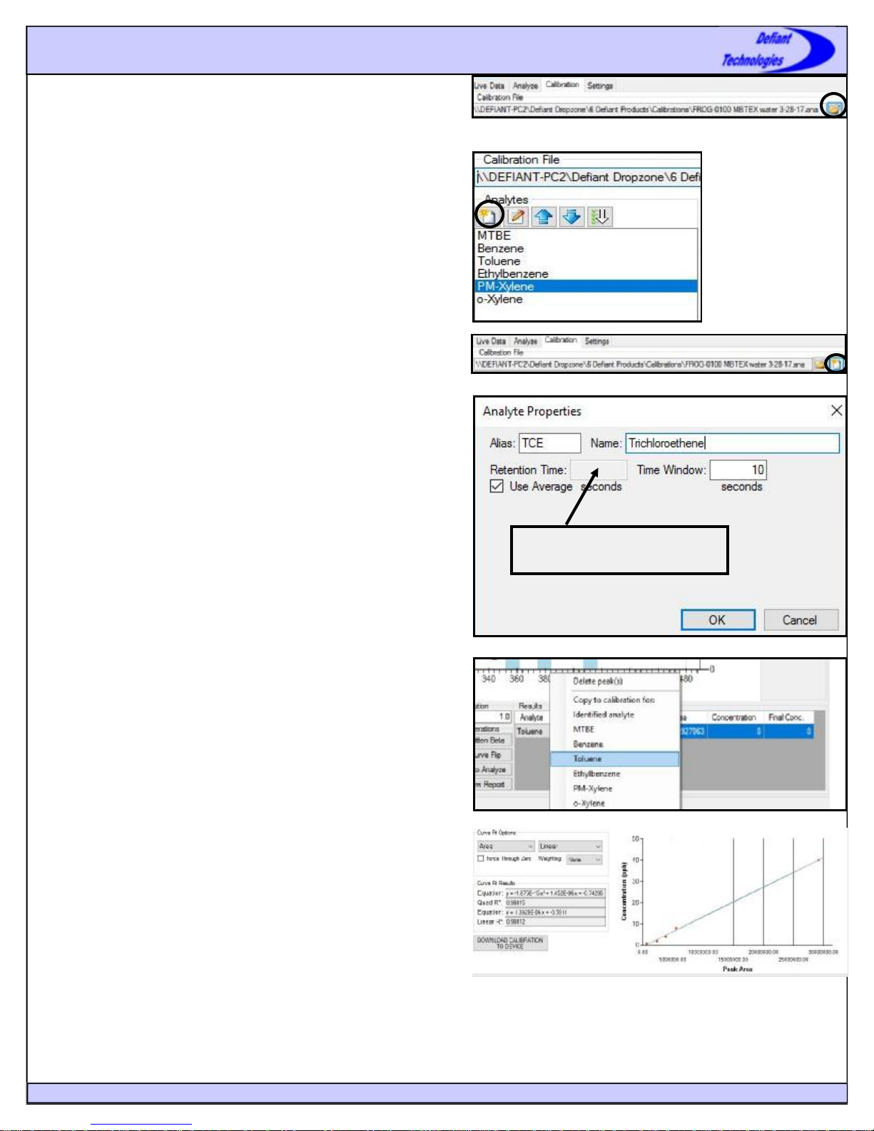
Calibration
It is necessary to calibrate the FROG for a desired application. A calibration must be
opened in the Ellvin Software for the FROG to correctly analyze samples.
Calibration files can be created (with analysis data from chemical standards) or
loaded (if someone else calibrated the FROG) with the software. Defiant
recommends re-calibrating the FROG at least every three weeks for the most
accurate analyses.
Calibration
Loading an Existing Calibration File
If the FROG was calibrated by someone else, the calibration file will must be loaded
along with the software. The calibration file can be found on the USB Drive located
in the zipper pouch in the FROG’s case. To load a calibration file complete the following steps:
1. Locate the file on the USB Drive. It is a file ending in .ana. Copy and paste the
file to a location on the computer that is easy to find.
2. In the calibration tab of the Ellvin GC Software click on the open icon to the
right of the “analyte file” box, locate the file that was copied and pasted and
open it (Figure 12).
3. Verify that the target analytes are listed under the analytes list (Figure 13).
4. If the FROG was calibrated at a different elevation than the one it will be used,
adjust retention times.
Creating a Calibration File
To create a calibration file do the following:
1. Create a new calibration file by clicking on the “new” icon to the right of the
calibration file box (Figure 14).
2. Label and save your new calibration file.
3. Add your analytes by clicking on the “new” icon underneath the analyte list
(Figure 13). Type in the analyte name and alias (which will appear on the display when running in standalone mode) and select OK. Repeat this step for
each target analyte until all desired analytes have been added.
Figure 12: Opening a Calibration File.
Figure 13: Analytes List and
adding new analytes.
Figure 14: Creating a New Calibration File
When adjusting retention times, the
new value goes here.
Generating and Adding Data to a Calibration
To create a calibration, a series of different known concentration samples must be
run on the FROG. Defiant recommends running five calibration standards from
lowest to highest concentration. Refer to later sections regarding running samples
and analyzing the data. The steps to generate and add data to a calibration are as
follows:
1. Run 5 known samples on the FROG starting with the lowest concentrations and
ending with the highest concentration, noting which concentration corresponds
to each run.
2. Analyze one of the sample runs in the analyze tab of the software (see page 9
for how to analyze data).
3. In the results table under the analyze tab, highlight the analyte you would like
to add calibration data for and enter in the known concentration
4. With the desired analyte selected in the results list, right click on the highlighted row and select the correct analyte from the list. Select yes when the software
asks if you want to copy the peaks to the current calibration, this sends the data
to the calibration file. Repeat steps 3 and 4 for all analytes at each concentration run.
Calibration Curve and Equations
Once data has been added to a calibration, Ellvin will create a calibration curve for
the target analyte(s). Figure shows an example curve. The calibration curve displays
the degree of correlation (R² value) between analyte standards of varying concentrations and the instrument’s response to them. The correlation is calculated as both a
linear equation and a second-order quadratic equation. The user may view the equations and chart for either Peak Area correlation or for Peak Height correlation. Ellvin
uses these parameters to calculate concentrations for future samples. Note that for
sample screening, a one point calibration may be used, this point should be the same
concentration of the action level for the screening.
Figure 15: Adding a New Analyte to a Calibration File
Figure 16: Sending Data to a Calibration File
Figure 17: Correlation Equations and Calibration Curve
Home
www.defiant-tech.com
4
Water Sampling
Water Sample Preparation Tips
• The sample volume for the FROG will always be
5mL.The system was calibration with 5mL samples, all
testing must be performed using 5mL samples.
• It is acceptable for water samples to have particulate
matter or sediment in them. This will not damage the
FROG.
• If the water is silty, it is best to load the sample directly
into the sparge bottle.
• Be mindful of the concentration of the sample. If the
sample smells, it is a good idea to dilute it.
• Do not run neat (undiluted) materials like crude oil or
solvents with the FROG.
Loading a Water Sample
1. Load 5mL of the water sample into the 5mL glass
syringe that comes with the FROG or into a plastic
5mL syringe. This can be done by either pulling the
liquid up through the front of the syringe or by
removing the plunger and filling the syringe through
the back.
2. Thread the green sparge needle into the sparge bottle,
leave the bottle in the dropped (down) position (Figure
18).
3. Connect Syringe to sample inlet on the instrument, it is
a luer-lock connection and the syringe will stay in
place (Figures 19 and 20).
4. Set valve on top of instrument to the “load water”
position so the red arrow points toward the connected
syringe (Figure 21).
5. Inject sample into the instrument; the sparge bottle
now holds the sample (Figure 22).
6. Lift the sparge bottle up into the raised (up) position.
Tighten sparge nut (counter clockwise) to hold bottle
in place (Figure 23).
7. Set the valve on top of instrument to the “run water”
position. The red arrow will now point toward the blue
tubing (Figure 24).
8. Remove empty syringe from instrument.
Step 2
Step 3
Figure 18: Sparge
Bottle in Dropped
(Down) Position
Figure 21: Valve
set to “Load Water”
Figure 19: Attaching and Detaching
Syringe from Sample Inlet
Steps 3,8
Figure 20: Sparge
Bottle in Dropped
(Down) Position
with 5mL Syringe
attached to FROG,
Sample is ready to
be loaded
Figure 22: Sample
Injected in Sparge
Bottle
Running a Sample
Once a water sample has been loaded, it is ready to be run
with the Frog.
1. With the FROG connected to the software use the play
button to start a run (Figure 25).
2. When the Frog is finished running the sample, empty
the sparge bottle, clean glassware by rinsing 3 times
with water, run a blank if there was a detection and
then proceed with sampling.
Figure 25: Play Button
to start run in Software
Home
Step 4 Step 5
Step 6
Figure 23: Lifting Sparge Bottle up and
tightening sparge nut to hold it in place
www.defiant-tech.com
Step 7
Figure 24: Changing Valve position
to “Run Water”
 Loading...