

Defiant DFI-7148-BK, DFI-7148-WH Use And Care Manual

THANK YOU
We appreciate the trust and condence you have placed in Deant through the purchase of this motion solar security
light. We strive to continually create quality products designed to enhance your home. Visit us online to see our full
line of products available for your home improvement needs. Thank you for choosing Deant!
USE AND CARE GUIDE
MOTION SOLAR SECURITY LIGHT
W
Questions, problems, missing parts?
Before returning to the store, call Deant Customer Service
8 a.m.-7 p.m., EST, Monday-Friday, 9 a.m. - 6 p.m., EST, Saturday
1-866-308-3976
HOMEDEPOT.COM
Item #1001727935
1001727927
Model #DFI-7148-BK
DFI-7148-WH
2
Table of Contents
Table of Contents ......................................2
Safety Information ....................................2
Warranty ...................................................2
3-Year Limited Warranty ........................2
Pre-Installation .........................................3
Planning Installation ..............................3
Description .............................................3
Initial Battery Charge .............................3
Mounting Location ................................3
Solar Light Fixture ..................................3
Solar Panel .............................................3
Specications ........................................4
Tools Required .......................................4
Hardware Included .................................5
Package Contents ..................................5
Installation ................................................6
Operation...................................................9
Care and Cleaning ..................................10
Troubleshooting ......................................10
Safety Information
PRECAUTIONS
□ Please read and understand this entire manual
before attempting to assemble, install, or operate
this light xture.
□ This light xture should be installed outdoors to a
wall or eave.
□ The light xture should be mounted approximately
8 ft. (2.4 m) above the ground.
□ Do not cut the solar panel wire. Discontinue use if
the wire becomes frayed or broken.
□ Do not immerse components in liquid.
□ Do not use any other charging device other than
the single solar charging panel provided with this
light. Doing so may result in injury or damage to
the light and voids any warranty.
□ Position the cord so that it is securely fastened and
will not result in a hazard (such as tripping).
WARNING: To prevent possible SERIOUS INJURY or
DEATH never allow small children near batteries. If battery
is swallowed, immediately notify a doctor.
WARNING: DO NOT mix old and new batteries. DO
NOT mix battery types - such as alkaline, heavy duty, and
rechargeable - in a single device. Battery leakage may occur.
WARNING: DO NOT DISPOSE OF BATTERIES IN FIRE.
BATTERIES MAY EXPLODE OR LEAK.
NOTICE: When replacing batteries, recycle used batteries or dispose
of them in accordance with local regulations.
□ This device complies with Part 15 of the FCC Rules.
Operation is subject to the following two conditions:
(1) this device may not cause harmful interference,
and (2) this device must accept any interference
received, including interference that may cause
undesired operation.
□ CAN ICES-005 (B)/NMB-005 (B)
Warranty
3-YEAR LIMITED WARRANTY
WHAT IS COVERED
This product is guaranteed to be free of factory defective parts and workmanship for a period of 3 years from date
of purchase. Purchase receipt is required for all warranty claims.
WHAT IS NOT COVERED
This guarantee does not include repair service, adjustment and calibration due to misuse, abuse or negligence, or
LEDs. Unauthorized service or modication of the product or of any furnitshed component will void this warranty in
its entirety. This warranty does not include reimbursement for inconvenience, installation, setup time, loss of use,
unauthorized service, or return shipping charges. This warranty is not extended to other equipment and components
that a customer uses in conjunction with this product.
No service parts available for this product.
Contact the Customer Service Team at 1-866-308-3976 or visit www.homedepot.com.

3 HOMEDEPOT.COM
Please contact 1-866-308-3976 for further assistance.
Pre-Installation
PLANNING INSTALLATION
Before installing the light xture, ensure that all parts are present. Compare parts with the Hardware Included and
Package Contents sections. If any part is missing or damaged, do not attempt to assemble, install, or operate this
light xture.
Estimated installation time: 30 minutes
DESCRIPTION
This light operates from a battery charged from a solar panel. It will also hold three “C” alkaline batteries which
are used as a backup power source. If the solar battery becomes depleted, the light will automatically switch to the
alkaline batteries. When the solar panel has recharged the solar battery, the light will automatically switch back to
the solar battery.
INITIAL BATTERY CHARGE
IMPORTANT: The solar panel requires full, direct sunlight to charge the battery. Clouds, rain, snow, and other weather conditions may not allow the
solar panel to completely recharge the battery. Other obstructions such as buildings or trees may block the sun as well.
When installing the solar panel, make sure it is aimed as described below with a minimum amount of obstructions. If possible, mount the panel facing
toward the southern sky.
□ PRIOR TO USE, the battery will require 3 to 7 days of full sun to completely charge with the control dial in the
OFF position. Plug the solar panel cable into the connector extending from the bottom of the battery case. If
possible, aim the solar panel toward the south and tilt it approximately 50° from horizontal. If the solar panel
cannot be aimed toward the south, then tilt the panel approximately 30° if possible.
□ Actual operating time will vary depending upon how frequently the light is turned on by the motion sensor.
□ Solar lighting is not designed to equal standard 120V lighting. The amount of light output is reduced to allow
the sun time to fully recharge the battery between lighting cycles.
□ Solar collection is only effective in direct sunlight. Every hour the light is on requires a minimum of 16 hours
of sunlight charging. Solar panels collect less than 10% of the sun’s energy.
MOUNTING LOCATION
The most important thing to remember for the operation of your solar powered motion sensing light is that it works
from the power received from direct sunlight. The more direct sunlight the solar panel receives in a day, the longer
the light will operate.
SOLAR LIGHT FIXTURE
The main unit contains the LEDs, motion sensor, and battery. When deciding where to mount this unit, keep in mind
that the motion sensor that activates the light has a “eld of vision” of 40 feet (12 meters) in front of the light and
about 180° detection angle at a surrounding air temperature of 77° F (25 °C).
SOLAR PANEL
The solar panel converts the sun’s energy into electricity, thus charging the battery stored in the solar light xture.
The solar panel requires direct sunlight falling onto the face of the solar panel for as long as possible over the
course of the day.
When choosing the location for the solar panel, make sure it is aimed toward the south and is tilted to a suitable
angle to allow as much direct sunlight to fall upon it as possible. Make sure there is a minimum amount of
obstructions between the solar panel and the sun.
Also, make sure your solar panel location is not too far away from the solar light xture for the wires to reach and
connect.
4
Pre-Installation (continued)
SPECIFICATIONS
Range
Up to 40 ft. (12 m) (Varies with surrounding temperature)
Sensing angle
Up to 180°
Lumens
Solar Power: 600 LM, Alkaline Battery: 200 LM
Power requirements
“C” Alkaline Batteries (3x) (not included)
Operating modes
Off, Test, Timer
Time delay
5 seconds to 5 minutes
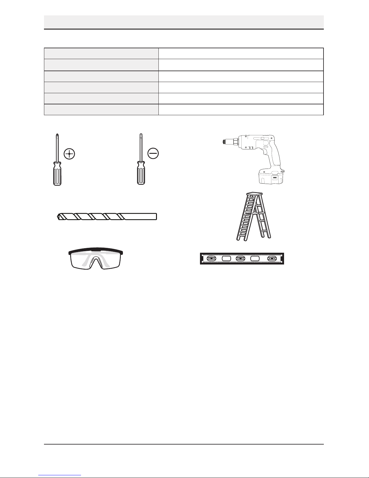
TOOLS REQUIRED
Phillips
screwdriver
1/8 in. Flathead
screwdriver
Drill
Drill bits (3/32 in.
and 7/32 in.)
Ladder
Safety goggles Level
5 HOMEDEPOT.COM
Please contact 1-866-308-3976 for further assistance.
Pre-Installation (continued)
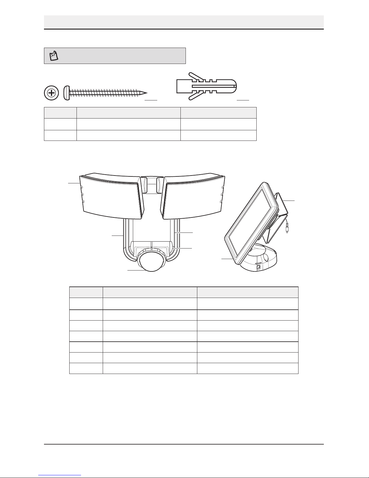
HARDWARE INCLUDED
NOTE: Hardware shown to actual size.
AA BB
Part Description Quantity
AA Mounting screw 4
BB Wall anchor 4
PACKAGE CONTENTS
W
Part Description Quantity
A Lamp head 1
B Light xture 1
C Motion sensor 1
D Mounting plate 1
E Control dial 1
F Solar panel 1
G Cord management system 1
A
E
D
F
G
B
C
6
Installation
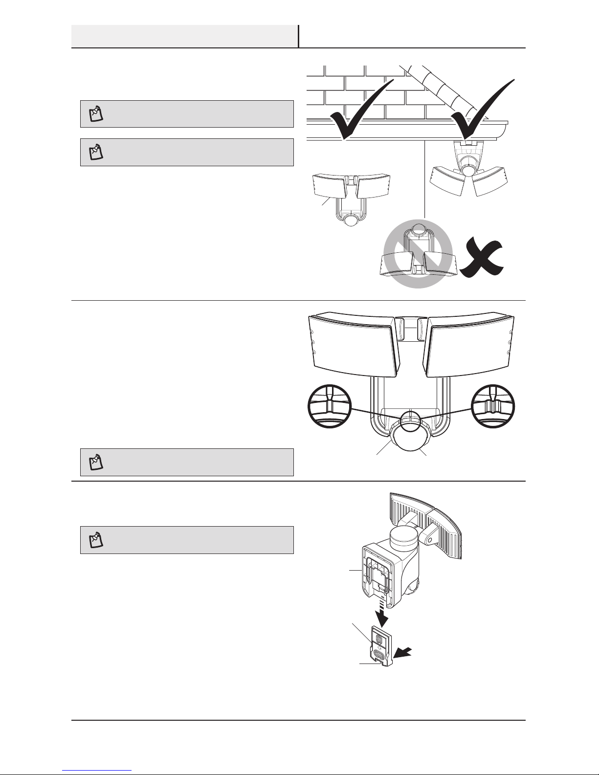
1
Determining the mounting
location
NOTE: The light xture should be mounted approximately
8 ft. (2.4 m) above the ground.
NOTE: Ensure the xture and the solar panel are located
close enough together for the cord to reach.
□ Determine the mounting location – wall or eave
mount.
□ Position the lamp head (A) in the general
direction of the desired light coverage.
Wall Mount
E
W
W
Eave Mount
2
Setting the sensor for wall or
eave mounting
□ For wall mounting, turn the ring (1) around
the sensor (C) clockwise until the “W” and the
single indicator is aligned with the mark on the
front of the sensor (C).
□ For eave mounting, turn the ring (1) around the
sensor (C) counterclockwise until the “E” and
the double indicator is aligned with the mark
on the front of the sensor (C).
NOTE: There is a detent at each setting to indicate proper
alignment of the sensor.
W
E
W
Wall Mount Eave Mount
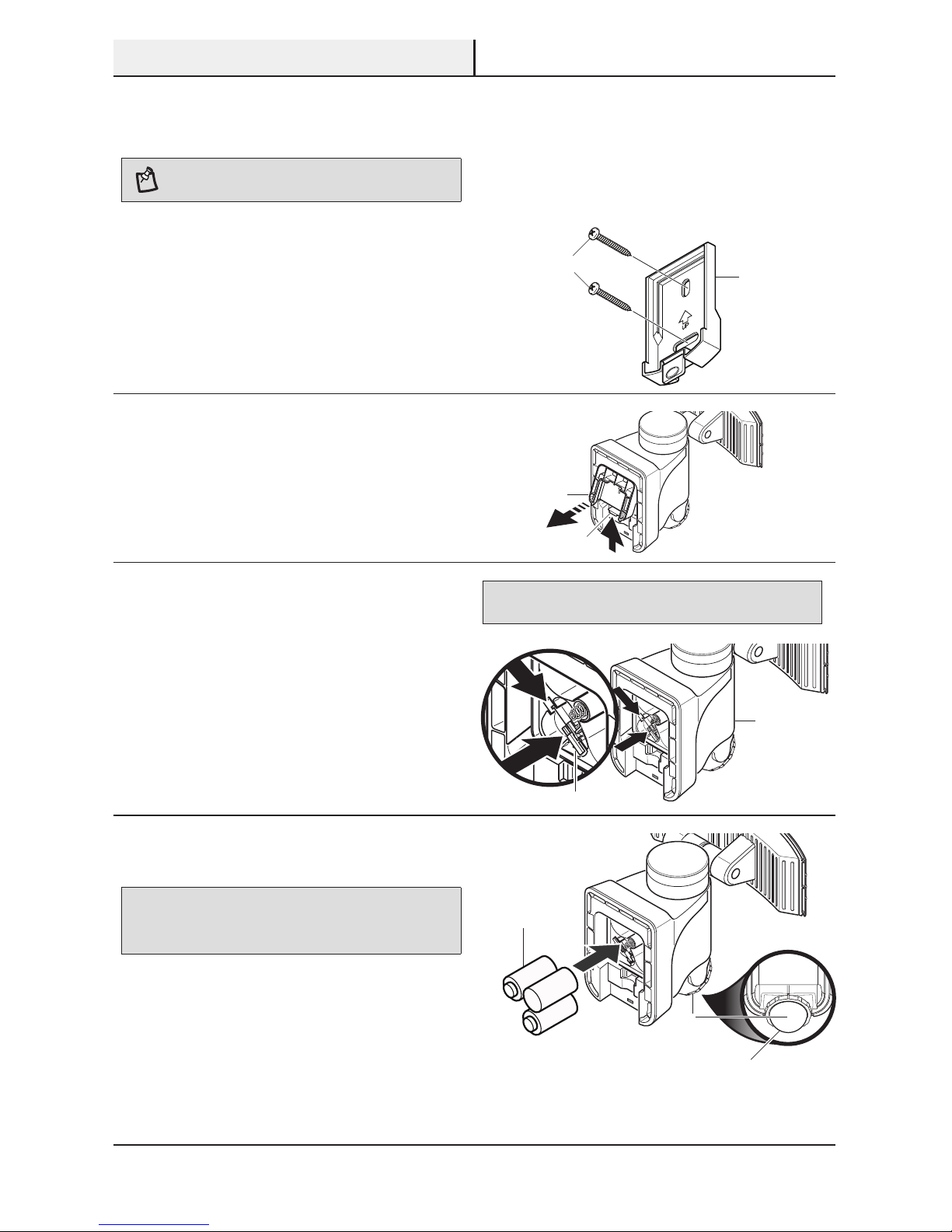
3
Removing the mounting plate
NOTE: This xture comes with a mounting plate (D). It is
pre-assembled on the light xture (B) for shipping.
□ Press the bottom tab (2) of the wall mounting
plate (D) and slide the mounting plate (D) from
the light body (B).
UP
OPEN
PRESS TO CLOSE
A
B
2
1 C
D
7 HOMEDEPOT.COM
Please contact 1-866-308-3976 for further assistance.
Installation (continued)
4
Installing the mounting plate
NOTE: Make sure there is enough vertical space above
the mounting plate to allow the light xture to be mounted.
□ Place the mounting plate (D) against the
mounting surface and ensure the mounting
plate (D) is level. Mark the hole locations.
□ If mounting to a wooden surface, drill two
3/32 in. holes into the mounting surface.
Install the two mounting screws (AA)
through the mounting plate (D) and into
the mounting surface.
□ If mounting to wall board or brick, drill two
7/32 in. holes into the mounting surface.
Insert the wall anchors (BB) and attach the
mounting plate (D) using the two mounting
screws (AA).
5
Removing the battery cover
□ Press up on the battery compartment cover (3)
locking tab (4) and swing the cover (3) out and
down to remove.
OPEN
PRESS TO CLOSE
OPEN
PRESS TO CLOSE
6
Connecting the solar battery
This light xture (B) is shipped with the internal,
rechargeable, Li-ion battery disconnected from the
light (B).
□ Gently press down on the wiring harness (5) as
shown by arrow 1.
□ Slide the mail connector into the female
connector as shown in arrow 2.
IMPORTANT: Once the the solar battery harness is connected,
there will be no need to touch this harness again.
1
2
1
2
7
Installing the batteries
IMPORTANT: The “C” batteries (6) are used when the rechargeable
solar battery is depleted. When the “C” batteries (6) are depleted,
a red LED (7) will ash inside the motion sensor (C) and the “C”
batteries(6) will need to be replaced.
□ Install three, 1.5V “C” batteries (6 - not
included) into the battery compartment. Make
sure the polarity of the batteries is correct.
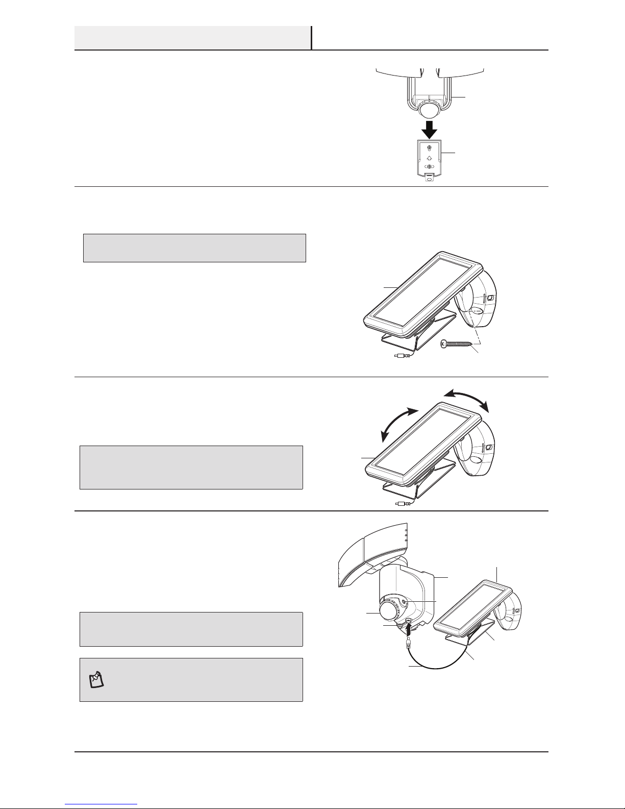
□ Replace the battery compartment cover (3).
D
AA
4
3
6
7
C
5
B
W
8
Installation (continued)
8
Mounting the light fixture
□ Slide the rear of the light xture (B) down onto
the mounting plate (D) until it snaps into place.
W
UP
9
Mounting the solar panel
IMPORTANT: Caulk around the base and on top of the screw heads
after installation.
□ Place the solar panel (F) against the mounting
surface and mark the mounting holes.
□ If mounting to a wooden surface, drill two
3/32 in. holes into the mounting surface.
Install the two mounting screws (AA)
through the base and into the mounting
surface.
□ If mounting to wall board or brick, drill two
7/32 in. holes into the mounting surface.
Insert the wall anchors (BB) and attach the
base using the two mounting screws(AA).
10
Adjusting the solar panel
□ Rotate the solar panel (F) to the desired angle.
IMPORTANT: The solar panel (F) must receive as much direct
sunlight over the course of the day as possible. Keep in mind that
shadows may block the sunlight from reaching the solar panel (F)
during the day.
11
Connecting the solar panel
to the light fixture
□ Carefully route the solar panel cable (8) to the
light xture (B). Remove the rubber plug (9)
from the bottom of the light xture (B) and
insert the end of the cable (8) into the opening.
IMPORTANT: Turn the control dial (E) on the side of the sensor (C)
to the OFF position and allow the battery to charge with 3 to 7 days of
full sunshine before testing.
NOTE: Wrap any excess solar panel cable (8) around the
cord management system (G) located on the rear of the
solar panel (F). Leave enough loose cable (8) to form a
drip loop (10).
E
W
B
D
AA
F
E
C
9
10
B
8
G
F
F
 Loading...