

Defiant DFI-5983-BZ, DFI-5983-WH Use And Care Manual
THANK YOU
We appreciate the trust and condence you have placed in Deant through the purchase of this motion security light.
We strive to continually create quality products designed to enhance your home. Visit us online to see our full line of
products available for your home improvement needs. Thank you for choosing Deant!
USE AND CARE GUIDE
MOTION SECURITY LIGHT
Questions, problems, missing parts?
Before returning to the store, call Deant Customer Service
8 a.m.-7 p.m., EST, Monday-Friday, 9 a.m. - 6 p.m., EST, Saturday
1-866-308-3976
HOMEDEPOT.COM
Item #1001318510
1001311060
Model #DFI-5983-BZ
DFI-5983-WH
2
Table of Contents
Table of Contents ......................................2
Safety Information ....................................2
Warranty ...................................................2
5-Year Limited Warranty ........................2
Pre-Installation .........................................3
Planning Installation ..............................3
Specications ........................................3
Tools Required .......................................3
Hardware Included .................................4
Package Contents ..................................4
Installation ................................................5
Operation...................................................7
Care and Cleaning ..................................10
Troubleshooting ......................................10
Safety Information
PRECAUTIONS
□ Please read and understand this entire manual
before attempting to assemble, install, or operate
this light xture.
□ This light xture requires a 120-Volt AC power
source.
□ Some codes require installation by a qualied
electrician.
□ This light xture must be properly grounded.
□ This light xture should be installed outdoors to a
wall or eave.
□ The light xture should be mounted approximately
8 ft. (2.4 m) above the ground. If the light xture
is mounted higher than recommended, aiming the
sensor down will reduce the coverage area.
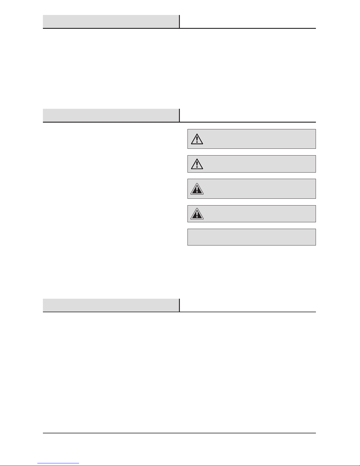
WARNING: Turn the power off at the circuit breaker or
fuse. Place tape over the circuit breaker switch and verify
power is off at the light xture.
WARNING: Risk of re. Keep the lamp heads at least
2in. (51mm) from combustible materials.
CAUTION: To avoid water damage and the risk of
electrical shock, the motion sensor controls must be facing
the ground when the installation is complete.
CAUTION: Burn hazard. Allow the light xture to cool
before touching.
NOTICE: Do not connect this light xture to a dimmer switch or
timer.
□ This device complies with Part 15 of the FCC Rules. Operation is subject to the following two conditions: (1)
this device may not cause harmful interference, and (2) this device must accept any interference received,
including interference that may cause undesired operation.
□ CAN ICES-3 (B)/NMB-3(B)
Warranty
5-YEAR LIMITED WARRANTY
WHAT IS COVERED
This product is guaranteed to be free of factory defective parts and workmanship for a period of 5 years from date
of purchase. Purchase receipt is required for all warranty claims.
WHAT IS NOT COVERED
This guarantee does not include repair service, adjustment and calibration due to misuse, abuse or negligence, or
LEDs. Unauthorized service or modication of the product or of any furnished component will void this warranty in
its entirety. This warranty does not include reimbursement for inconvenience, installation, setup time, loss of use,
unauthorized service, or return shipping charges. This warranty is not extended to other equipment and components
that a customer uses in conjunction with this product.
Contact the Customer Service Team at 1-866-308-3976 or visit www.homedepot.com.
3 HOMEDEPOT.COM
Please contact 1-866-308-3976 for further assistance.
Pre-Installation
PLANNING INSTALLATION
Before installing the light xture, ensure that all parts are present. Compare parts with the Hardware Included and
Package Contents sections. If any part is missing or damaged, do not attempt to assemble, install, or operate this
light xture.
Estimated installation time: 30 minutes
SPECIFICATIONS
Range
Up to 70 ft. (21.3 m) (Varies with surrounding temperature)
Sensing angle
Up to 180°
Electrical load - LED
25 Watts
Lumens
2050
Power requirements
120 VAC, 60 Hz
Operating modes
Test, Motion activated, Manual
Time delay
1, 5, 20 minutes
DualBrite timer
Off, 3 hours, 6 hours, dusk-to-dawn
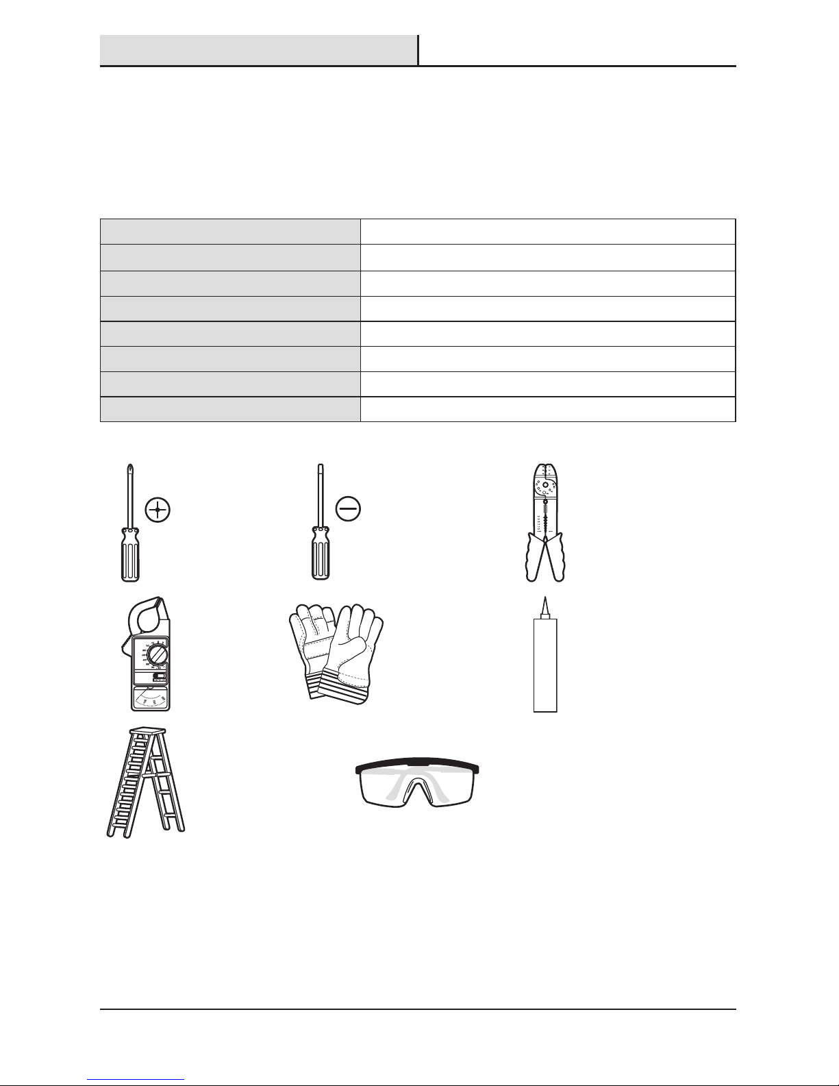
TOOLS REQUIRED
Phillips
screwdriver
1/8 in. Flathead
screwdriver
Wire strippers/
cutters
Circuit tester Work gloves
Silicone
sealant
Ladder Safety goggles
4
Pre-Installation (continued)
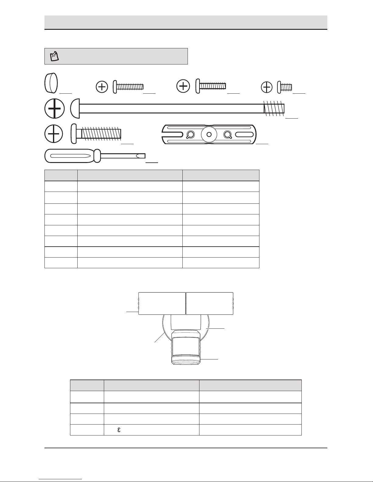
HARDWARE INCLUDED
NOTE: Hardware shown to actual size.
AA BB CC DD
EE
FF
FRONT
GG
HH
Part Description Quantity
AA Rubber plug 1
BB Mounting bracket screw 2
CC Mounting bracket screw 2
DD Mounting bracket screw 2
EE Large mounting bolt (pre-installed) 1
FF Small mounting bolt 1
GG Mounting bracket (not to scale) 1
HH Mini screwdriver 1
PACKAGE CONTENTS
Part Description Quantity
A Lamp head 2
B Light xture 1
C Motion sensor 1
D
1-2- asy Connect™
1
C
A
D
B
5 HOMEDEPOT.COM
Please contact 1-866-308-3976 for further assistance.
Installation
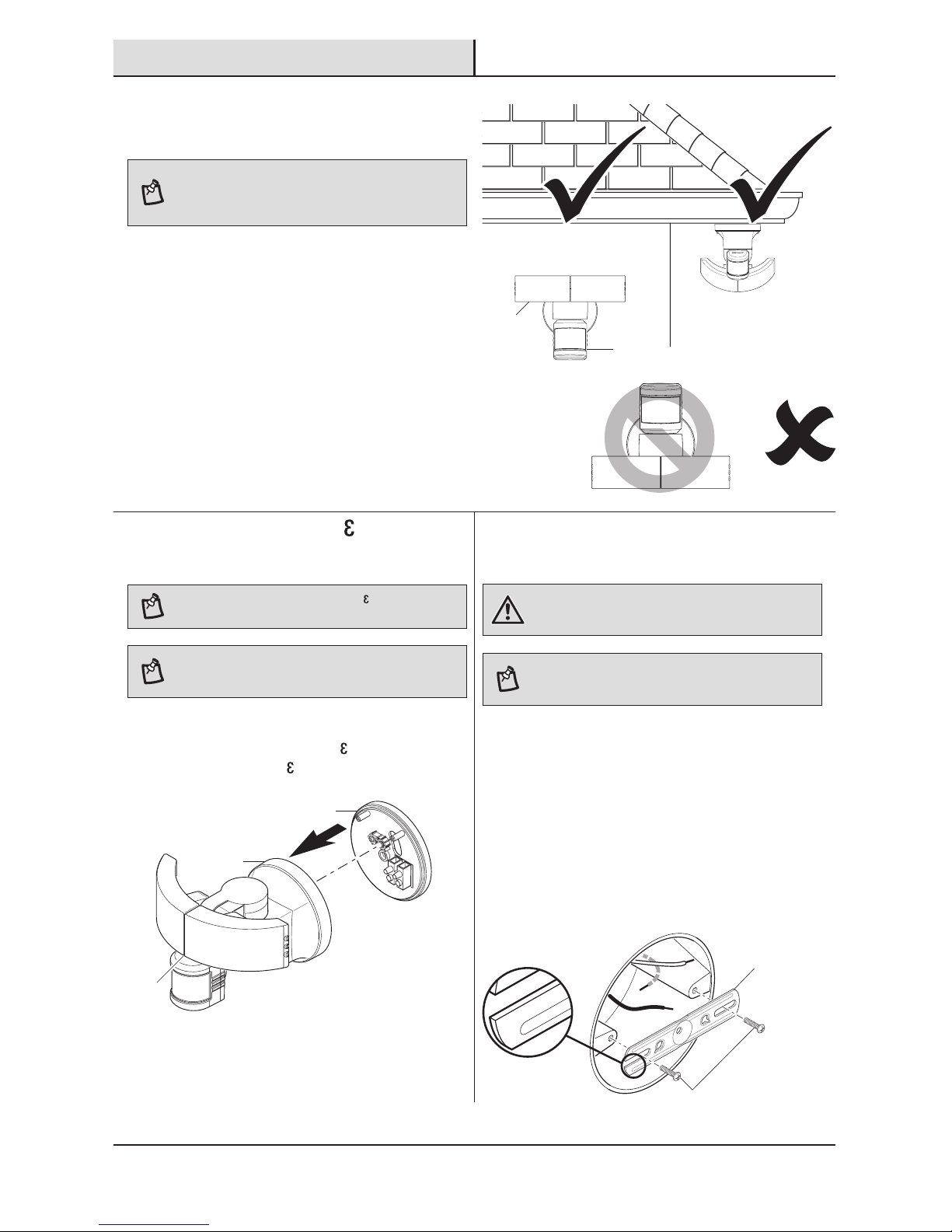
1
Determining the mounting
location
NOTE: The light xture should be mounted approximately
8 ft. (2.4 m) above the ground. If the light xture is
mounted higher than recommended, aiming the sensor
down will reduce the coverage area.
□ Determine the mounting location – wall or eave
mount.
□ Position the lamp heads (A) in the general
direction of the desired light coverage.
□ If needed, rotate the motion sensor (C) so the
controls face the ground after installation.
Wall Mount
Eave Mount
180°
THIS SIDE UP
2
Removing the 1-2- asy
Connect™
NOTE: This xture comes with a 1-2- asy Connect™ (D).
It is pre-assembled on the light xture (B) for shipping.
NOTE: The large mounting bolt (EE) is pre-installed in
the light xture (B). Do not attempt to remove the large
mounting bolt (EE).
□ Unscrew the large mounting bolt (EE) connecting
the light xture (B) to the 1-2- asy Connect™ (D)
and remove the 1-2- asy Connect™ (D).
3
Installing the mounting bracket
WARNING: Turn the power off at the circuit breaker or
fuse. Place tape over the circuit breaker switch and verify
power is off at the light xture.
NOTE: Six mounting bracket screws of various sizes are
included. The installation will only require two. Discard the
unused mounting bracket screws after installation.
□ Remove the existing light xture.
□ Install the mounting bracket (GG) with the
stamped word “FRONT” facing away from the
junction box. Use the mounting bracket screws
(BB, CC, or DD) that best t the junction box.
□ Firmly pull on the mounting bracket to verify
it is securely mounted to the junction box. If
necessary, use the screws that were removed
from the existing light xture.
FRONT
FRO NT
A
C
EE
D
B
BB, CC, or DD
GG
6
Installation (continued)
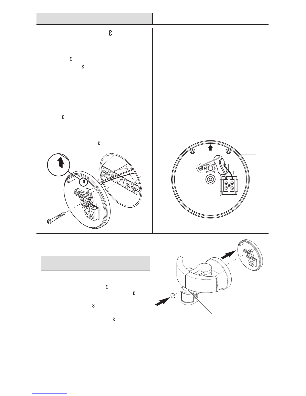
4
Installing the 1-2- asy
Connect™
□ Route the junction box wires through a hole in
the 1-2- asy Connect™ (D).
□ Place the 1-2- asy Connect™ (D) against the
junction box.
□ When mounting to a wall, the “UP” arrow
must point upward.
□ When mounting to an eave, the “UP” arrow
must point toward the building.
□ Insert the small mounting bolt (FF) through the
1-2- asy Connect™ (D) hole located below
the threaded hole, and thread it into the center
hole of the mounting bracket (GG). Tighten the
bolt (FF) securely.
□ Firmly pull on the 1-2- asy Connect™ to verify
it is securely attached to the mounting bracket.
FRONT
N (White/
Blanc/Blanco)
GND
Terre
Tierra
UP/Haut/Arriba
L (Black/
Noir/Negro)
UP/Haut/Arriba
5
Making the electrical
connections
□ Insert the junction box wires into the side of
the terminal block and around the ground
screw. Tighten terminal block screws using
the mini-screwdriver (HH) and ground screw to
secure the wires.
□ Insert the white wire from the junction box
into the terminal marked “N (White)”.
□ Insert the black wire from the junction box
into the terminal marked “L (Black)”.
□ Connect the bare or green ground wire
from the junction box to the ground screw
(marked with “GND”).
N (White/
Blanc/Blanco)
GND
Terre
Tierra
UP/Haut/Arriba
L (Black/
Noir/Negro)
6
Mounting the light fixture
NOTICE: The two pins on the rear of the light xture must be
inserted into the terminal block for the light to work.
□ Align the bottom edge of the light xture (B) with
the bottom edge of the 1-2- asy Connect™
(D). Tilt the light xture (B) toward the 1-2- asy
Connect™ (D), making sure the light xture (B) is
centered on the 1-2- asy Connect™ (D).
□ Tighten the large mounting bolt (EE) securely
through the center of the 1-2- asy Connect™
(D). Do not overtighten.
□ Push the rubber plug (AA) rmly into the
mounting bolt hole on the light xture (B).
EE
AA
D
B
D
D
FF
GG
7 HOMEDEPOT.COM
Please contact 1-866-308-3976 for further assistance.
Installation (continued)
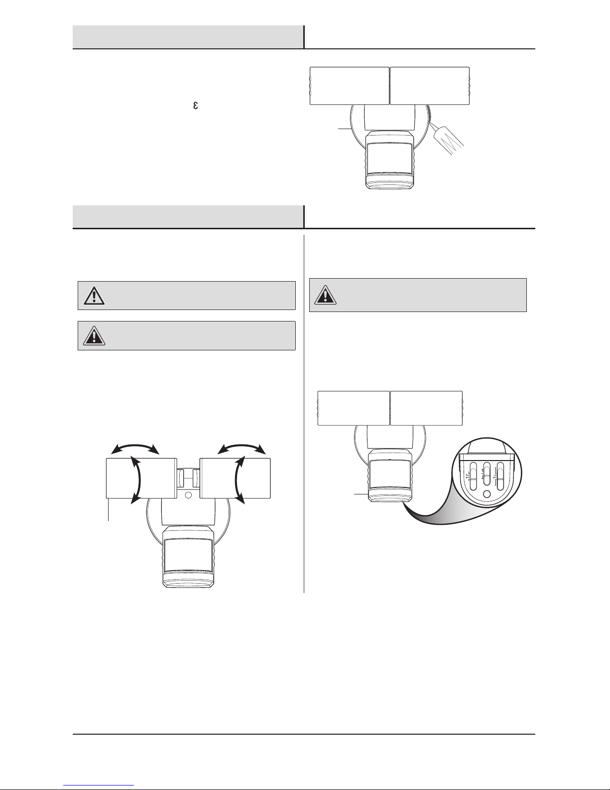
7
Caulking around the light
fixture
□ Caulk around the 1-2- asy Connect™ (D) and
mounting surface with silicone sealant (not
included).
Operation
1
Adjusting the lamp heads
WARNING: Risk of re. Keep the lamp heads at least
2in. (51mm) from combustible materials.
CAUTION: Keep lamp heads 30° below horizontal to
avoid water damage and electrical shock.
□ Turn the power on at the circuit breaker or fuse
and turn on the wall switch.
□ If needed, gently grasp the lamp heads (A) and
tilt them up or down or side to side to adjust
the light coverage area.
2
Rotating the sensor controls
downward
CAUTION: To avoid water damage and risk of electrical
shock, the motion sensor controls must be facing the
ground when installation is complete.
□ Rotate the motion sensor (C) so the controls
face toward the ground.
1 MIN 5 MIN
TEST 20 MIN
L M H
OFF 3H
DUSK TO DAWN
6H
ON TIME
SENS.
DUAL BRITE
D
C
A
8
Operation (continued)
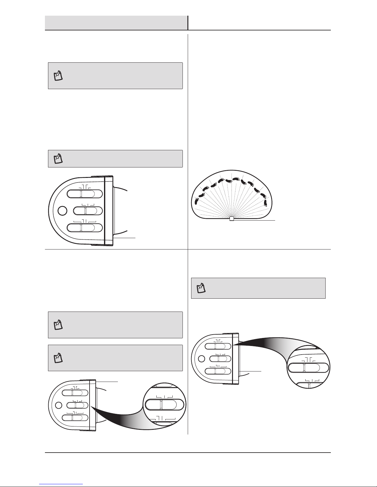
3
Setting the sensor for testing
NOTE: When the “ON-TIME” switch is set to the “TEST”
position, the light xture will operate during the day or
night. The light will stay on for 8 seconds after all motion
is stopped.
□ Set the “ON-TIME” switch to the “TEST”
position.
□ Set the “DUALBRITE” switch to the “OFF”
position.
□ Slide the “SENS” switch to the “L” (low)
position.
NOTE: The motion sensor will need to completely warm
up (60 seconds) before beginning the setup process.
1 MIN 5 MIN
TEST 20 MIN
L M H
OFF 3H
DUSK TO DAWN
6H
ON TIME
SENS.
DUAL BRITE
4
Adjusting the motion sensor
detection zone
□ Perform a “walk test”: walk in an arc across
the front of the motion sensor (C).
□ Watch the light. The light will come on and the
red LED will ash indicating motion has been
detected.
□ Stop, wait for the light to turn off, and then
begin walking again.
□ Continue this process until the detection zone
has been established.
□ If needed, gently grasp the motion sensor (C)
and move it from side to side or up and down
to adjust the detection zone.
5
Adjusting the SENS switch
□ To increase the detection zone, slide the
“SENS” switch toward the “H” (high) position.
□ To decrease the detection zone, slide the
“SENS” switch toward the “L” (low) position.
NOTE: The motion sensor (C) is more sensitive to motion
moving across the front of the sensor. The motion sensor
(C) is less sensitive to motion moving directly toward the
front of the sensor.
NOTE: The higher the “SENS” setting (sensitivity), the
greater the possibility of false triggering. To reduce false
triggering, slide the “SENS” switch toward the “L” (low)
setting.
1 MIN 5 MIN
TEST 20 MIN
L M H
DUSK TO DAWN
6H
ON TIME
SENS.
1 MIN 5 MIN
TEST 20 MIN
L M H
OFF 3H
DUSK TO DAWN
6H
ON TIME
SENS.
DUAL BRITE
6
Adjusting the ON-TIME switch
NOTE: The “ON-TIME” switch determines the amount of
time the light will stay on full bright after all motion has
stopped.
□ Set the “ON-TIME” switch to the 1, 5, or 20
minute position.
1 MIN 5 MIN
TEST 20 MIN
L M H
ON TIME
1 MIN 5 MIN
TEST 20 MIN
L M H
OFF 3H
DUSK TO DAWN
6H
ON TIME
SENS.
DUAL BRITE
C
C
C
C
 Loading...