

Defiant DF-5512-WH-D Use And Care Manual
THANK YOU
We appreciate the trust and condence you have placed in Deant through the purchase of this motion security light.
We strive to continually create quality products designed to enhance your home. Visit us online to see our full line of
products available for your home improvement needs. Thank you for choosing Deant!
USE AND CARE GUIDE
MOTION SECURITY LIGHT
Questions, problems, missing parts? Before returning to the store,
call Deant Customer Service
8 a.m. - 6 p.m., EST, Monday - Friday
1-866-308-3976
HOMEDEPOT.COM
Item #987829
Model #DF-5512-WH-D
2
Table of Contents
Table of Contents ......................................2
Safety Information ....................................2
Precautions ............................................2
Warranty ...................................................2
2-Year Warranty .....................................2
Specifications ...........................................3
Pre-Installation .........................................3
Planning Installation ..............................3
Tools Required .......................................3
Hardware Included .................................4
Package Contents ..................................5
Mounting Locations ...............................5
Installation ................................................6
Operation...................................................9
Care and Cleaning ..................................12
Troubleshooting ......................................12
Safety Information
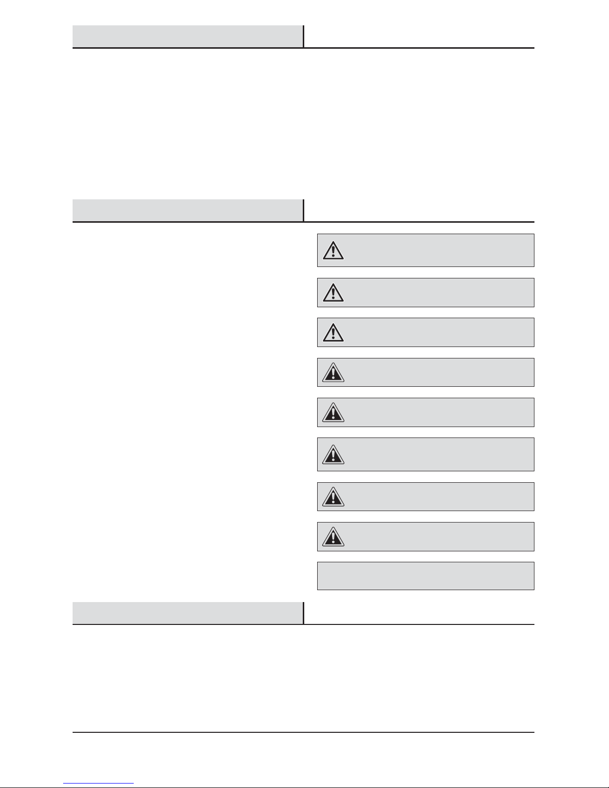
PRECAUTIONS
Please read and understand this entire manual before
attempting to assemble, install, or operate this light
xture.
This light xture requires 120-volts AC.
Some codes require installation by a qualied electrician.
This light xture must be properly grounded.
This light xture is intended for use with the enclosed
gasket and with a junction box marked for use in wet
locations.
Use a clean glove or cloth when handling the new bulb.
Use isopropyl (rubbing) alchohol to clean the bulb if it is
touched with bare hands.
For proper operation, this light xture should be:
Ƒ Installed outdoors to a wall or eaves
Ƒ Installed 8 ft. (2.4 m) above the ground (If the light
xture is mounted higher than recommended,
aiming the sensor down will reduce the coverage
area.)
Ƒ Do not leave the “ON-TIME” switch in the “TEST”
position. The frequent ON/OFF cycling of the light
xture will reduce the life of the bulb
Ƒ Use only T3 150W (maximum), tungsten halogen
bulb (120 VAC)
WARNING: Turn the power off at the circuit breaker or
fuse. Place tape over the circuit breaker switch and verify
power is off at the light xture.
WARNING: Risk of re. Do not aim the bulb at a
combustible surface within 3 ft. (1 m).
WARNING: Risk of re. Keep the bulb at least 2in.
(51mm) from combustible materials.
CAUTION: Keep the motion sensor at least 1 in. (25 mm)
away from the bulb.
CAUTION: Keep the bulb holders 30° below horizontal to
avoid water damage and electrical shock.
CAUTION: To avoid water damage and the risk of
electrical shock, the motion sensor controls must be facing
the ground when the installation is complete.
CAUTION: Burn hazard. Allow the light xture and the
bulb to cool before touching.
CAUTION: Do not cut any wires with factory installed
wire connectors or remove the wire connectors.
NOTICE: Do not connect this light xture to a dimmer switch or
timer.
Warranty
2-YEAR WARRANTY
Contact the Customer Service Team at 1-866-308-3976 or visit www.homedepot.com.
3 HOMEDEPOT.com
Please contact 1-866-308-3976 for further assistance.
Specications
Range
Up to 100 ft. (30 m) - Varies with surrounding temperature
Sensing angle
Up to 270°
Electrical load - incandescent
Up to 300 watt maximum (Up to 150 watt maximum per bulb holder)
Power requirements
120 VAC, 60 Hz
Operating modes
Test, Auto, Manual
Bulb modes
Security, BulbSaver, AlertFlash
Time delay
1, 5, 20 minutes
DualBrite timer
Off, 3 hours, 6 hours, dusk-to-dawn
Replacement bulb
T3 150W, halogen 120 VAC
Pre-Installation
PLANNING INSTALLATION
Before installing the light xture, ensure that all parts are present (see Hardware Included on page 4). If any part is
missing or damaged, do not attempt to assemble, install, or operate this light xture.
Estimated installation time: 30 minutes
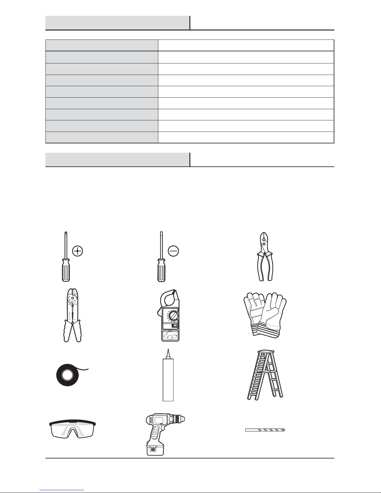
TOOLS REQUIRED
Phillips
screwdriver
Flathead
screwdriver
Pliers
Wire strippers/
cutters
Circuit tester Work gloves
Electrical tape Silicone sealant Ladder
Safety goggles Drill
3/16” (5mm)
Drill bit
4
Pre-Installation (continued)
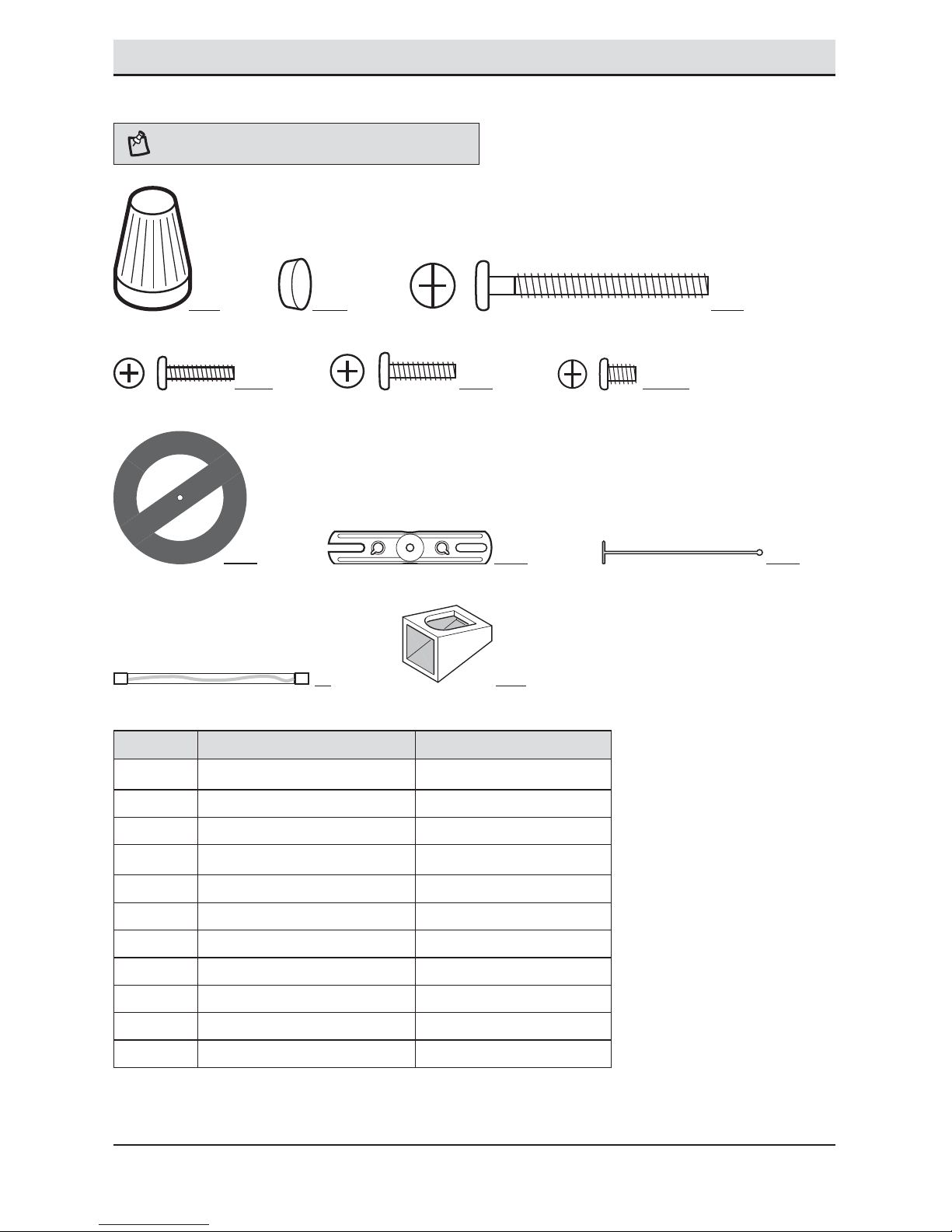
HARDWARE INCLUDED
NOTE: Hardware shown to actual size.
AA BB CC
DD EE FF
GG
FRONT
HH II
JJ KK
Part Description Quantity
AA Wire connector 3
BB Rubber plug 1
CC Mounting bolt 1
DD Mounting bracket screw 2
EE Mounting bracket screw 2
FF Mounting bracket screw 2
GG Gasket (not to scale) 1
HH Mounting bracket (not to scale) 1
II Plastic hanger (not to scale) 1
JJ
T3 halogen bulb (not to scale) 2
KK Light shield (not to scale) 1
5 HOMEDEPOT.com
Please contact 1-866-308-3976 for further assistance.
Pre-Installation (continued)
PACKAGE CONTENTS
Part Description Quantity
A Bulb holder 2
B Canopy 1
C Motion sensor 1
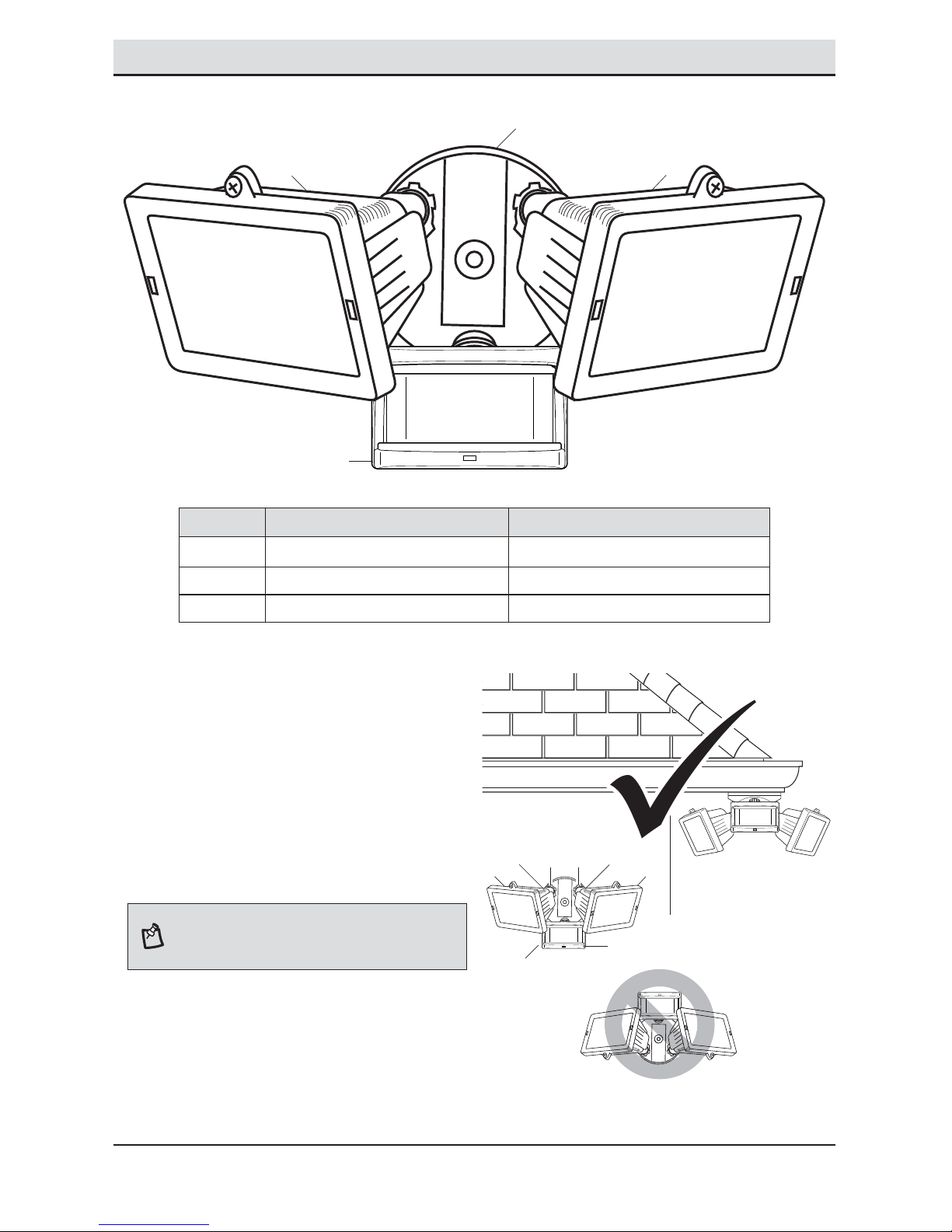
MOUNTING LOCATIONS
Ƒ Determine the mounting location – a wall or under
an eave.
Ƒ Position bulb holders (A) in the general direction
of the desired light coverage and tighten the lock
nuts (1) and the thumb screws (2).
Ƒ If needed, lift the motion sensor (C) up and
rotate it so the controls face the ground after
installation. Tighten the clamp screw (3) when
done. Do not overtighten.
NOTE: If the motion sensor (C) pops out of the ball joint,
loosen the clamp screw (3), push the motion sensor (C)
back into the ball joint, and tighten the clamp screw (3). Do
not overtighten.
Wall Mount
Eave Mount
C
A
A
B
AA
C
11
22
3
6
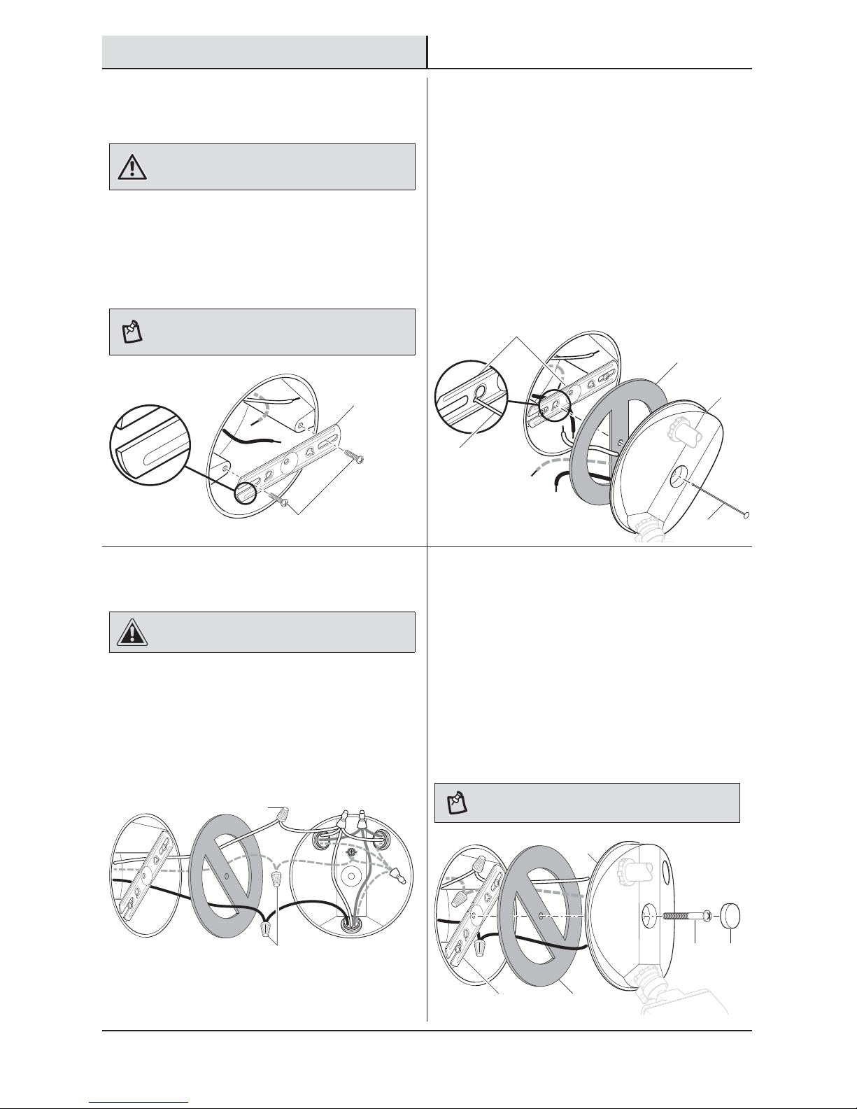
Installation
1
Installing the Mounting
Bracket
WARNING: Turn the power off at the circuit breaker or
fuse. Place tape over the circuit breaker switch and verify
power is off at the light xture.
Ƒ Remove the existing light xture.
Ƒ Install the mounting bracket (HH) with the
stamped word “FRONT” facing away from the
junction box. Use the mounting bracket screws
(DD, EE, or FF) that best t the junction box.
NOTE: Firmly pull on the mounting bracket to verify it is
securely mounted to the junction box. If necessary, use the
screws that were removed from the existing light xture.
FRON
T
FRONT
2
Hanging the Light Fixture
Temporarily
Ƒ Insert the small end of the plastic hanger (II)
through the center hole of the canopy (B) and
the gasket (GG).
Ƒ Insert the small end of the plastic hanger (II)
into one of the two small, slotted holes on the
mounting bracket (HH).
Ƒ Route the light xture wires through the large
holes in the gasket (GG).
FR
ON
T
FR
O
NT
3
Wiring the Light Fixture
CAUTION: Do not cut any wires with factory installed
wire connectors or remove the wire connectors.
Ƒ Connect the light xture wires to the junction
box wires with wire connectors (AA):
Ƒ White to white
Ƒ Black to black
Ƒ Bare or green ground wire to house ground
FR
ON
T
4
Mounting the Light Fixture
Ƒ Remove the plastic hanger (II).
Ƒ Insert the small end of the mounting bolt (CC)
through the center hole of the canopy (B) and
the gasket (GG).
Ƒ Align the mounting bolt (CC) with the center
hole in the mounting bracket (HH) and tighten
securely. Do not overtighten.
Ƒ Push the rubber plug (BB) rmly into the
mounting bolt hole on the canopy (B).
NOTE: Make sure all the wires are inside the junction box
before attaching the canopy (B) to the junction box.
FR
ON
T
DD, EE, or FF
HH
HH
II
GG
B
II
AA
AA
HH
GG
CC BB
B
7 HOMEDEPOT.com
Please contact 1-866-308-3976 for further assistance.
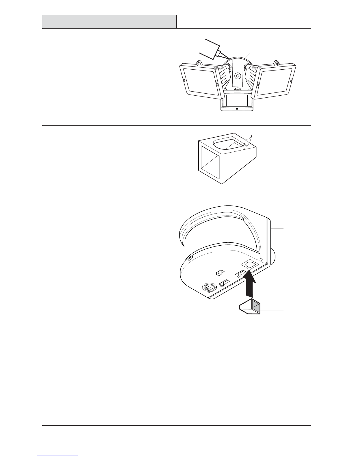
Installation (continued)
5
Caulking Around the Light
Fixture
Ƒ Caulk around the canopy (B) and mounting
surface with silicone sealant (not included).
6
Installing the Light Shield
If the light xture does not come on at dusk or turns
off unexpectedly, then another light source may be
activating the daylight turn-off (photocell) feature.
Possible sources of light interference are street lights,
landscape lighting, other security lights or lanterns,
or an interior house light shining through a window. It
could also be reective light, such as from a pool or
light colored wall.
To install the light shield (KK):
Ƒ Remove the protective backing from the
bottom of the light shield (KK).
Ƒ Position light shield (KK) over the photocell on
the bottom of the motion sensor (C) with the
opening facing away from the interfering light.
Ƒ Press the adhesive side rmly against the
photocell to mount it permanently in place.
ON-TIME
RANGE
DU
AL BRITE™
MIN MA
X
TE
ST 1 5 20
MINUTE
S
OFF 3 6 DUSK TO
HOUR
DA
WN
LAMP MODE
NORMAL SOFT FL
AS
H
B
KK
C
KK
8
Installation (continued)
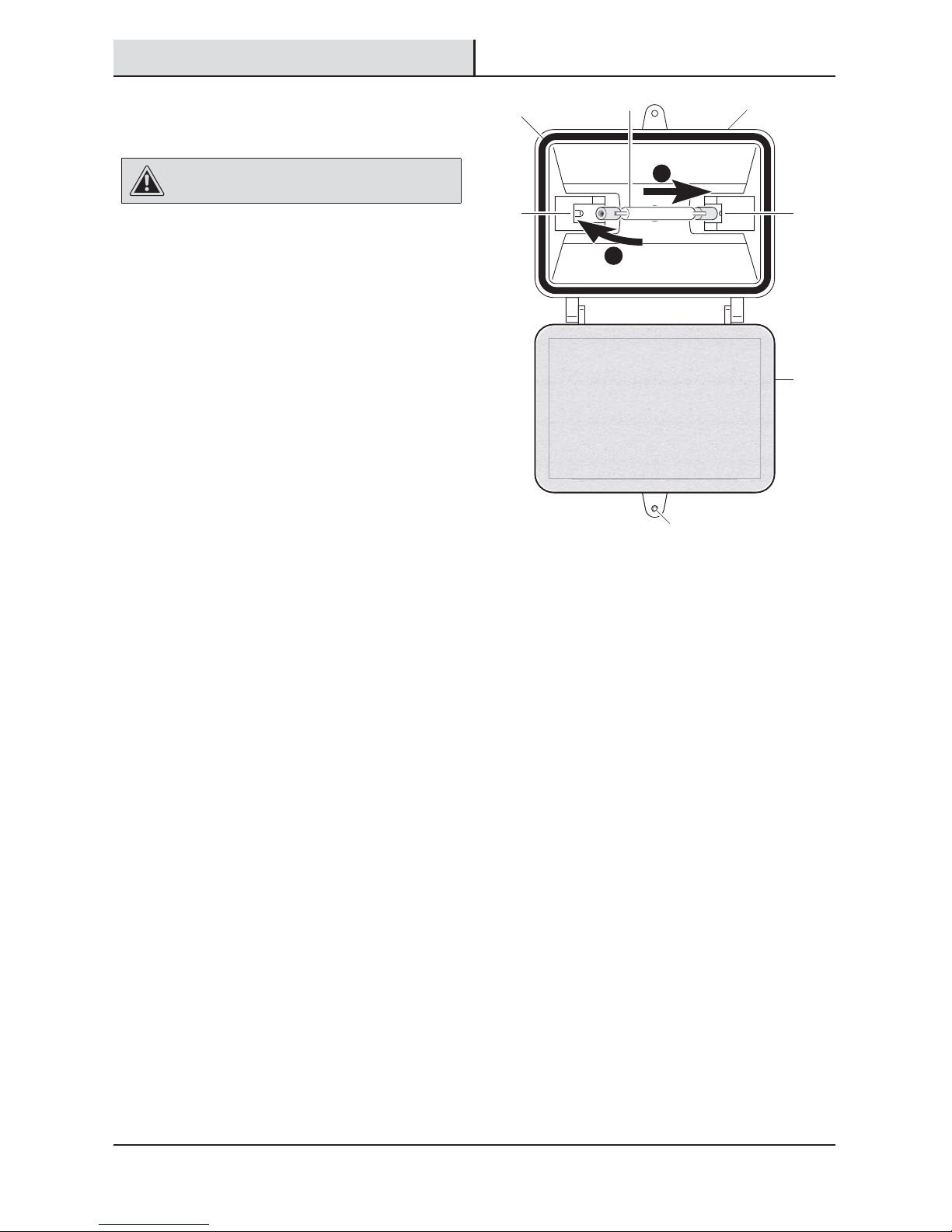
7
Replacing a Bulb
CAUTION: Burn hazard. Allow the light xture and the
bulb to cool before touching.
Use a clean glove or cloth when handling the new
bulb. Use isopropyl (rubbing) alchohol to clean the bulb
if it is touched with bare hands.
Ƒ Using a phillips screwdriver (not included),
loosen the glass cover locking screw (1) on the
bulb holder (A) and lower the glass cover (2).
Ƒ Remove the bulb (JJ) from the box.
Ƒ Place one end of the bulb (JJ) on the contact
in the right bulb socket (3). While pushing the
bulb (JJ) against the contact, lower the other
end of the bulb (JJ) onto the contact in the
left bulb socket (4). The bulb (JJ) should spin
easily if it is seated properly.
Ƒ Before closing the glass cover (2), make sure
the gasket (5) is seated properly in the groove
around the edge of the bulb holder (A). Close
the glass cover (2) and tighten the locking
screw (1) securely.
Ƒ To remove the bulb (JJ), push the bulb (JJ) to
the right until the left side of the bulb (JJ) is
clear of the left bulb socket (4).
1
2
43
5
1
JJ A
2
9 HOMEDEPOT.com
Please contact 1-866-308-3976 for further assistance.
Operation
1
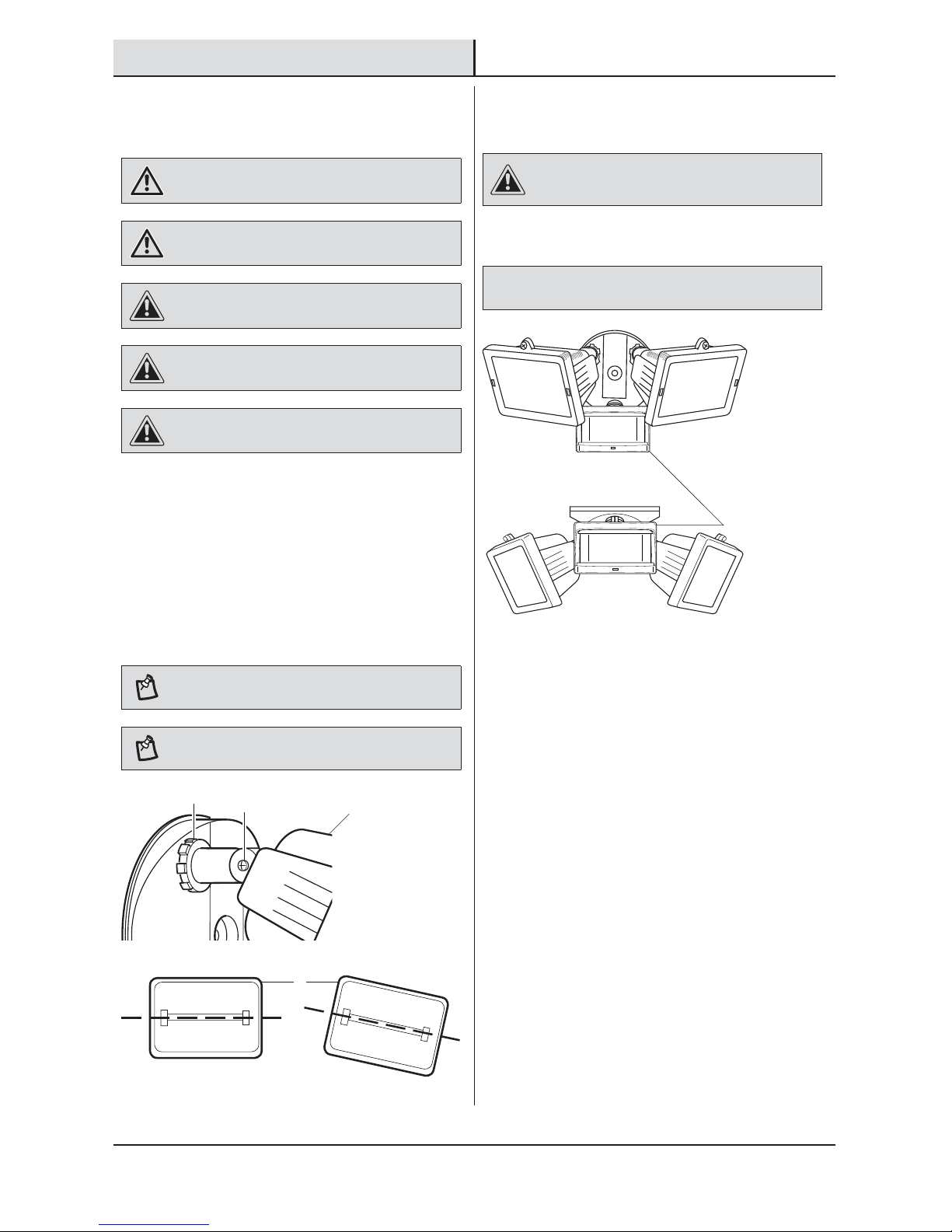
Adjusting the Bulb Holders
WARNING: Risk of re. Do not aim the bulb at a
combustible surface within 3 ft. (1 m).
WARNING: Risk of re. Keep the bulb at least 2in.
(51mm) from combustible materials.
CAUTION: Burn hazard. Allow the light xture and the
bulb to cool before touching.
CAUTION: Keep the sensor at least 1 in. (25 mm) away
from the bulb.
CAUTION: Keep the bulb holders 30° below horizontal to
avoid water damage and electrical shock.
Ƒ Turn the power on at the circuit breaker or fuse
and turn on the wall switch.
Ƒ Loosen the lock nut (1) and screw (2) to
adjust the bulb holder (A) for the desired light
coverage.
Ƒ Tighten the lock nut (1) and screw (2). Once
the lock nut (1) and screw (2) have been
tightened, turn the bulb holder (A) so that it is
horizontal.
NOTE: Do not rotate the bulb holder more than 180° from
the factory setting.
NOTE: The halogen light must be mounted horizontally
(+/- 4°).
CORRECT INCORRECT
2
Rotating Sensor Controls
Downward
CAUTION: To avoid water damage and risk of electrical
shock, the motion sensor controls must be facing the
ground when installation is complete.
Ƒ Rotate the motion sensor (C) so the controls
face toward the ground.
NOTICE: All clearances must be maintained. See Safety Information
on page 2.
1
2
A
A
C
 Loading...