

Defiant 53302161 Use And Care Manual
THANK YOU
We appreciate the trust and confidence you have placed in Defiant through the purchase of this LED light. We strive
to continually create quality products designed to enhance your home. Visit us online to see our full line of products
available for your home improvement needs. Thank you for choosing Defiant!
USE AND CARE GUIDE
LED OUTDOOR AREA LIGHT
Questions, problems, missing parts? Before returning to the store,
call Defiant Customer Service
8 a.m. - 7 p.m., EST, Monday - Friday
9 a.m. - 6 p.m., EST, Saturday
1-866-308-3976
HOMEDEPOT.COM
Item # 1002757105
Model # 53302161
2
Table of Contents
Table of Contents ......................................2
Safety Information ....................................2
Warranty ...................................................2
Pre-Installation .........................................3
Planning Installation ..............................3
Tools Required .......................................3
Package Contents ..................................3
Hardware Included .................................3
Installation ................................................4
Maintenance .............................................7
Care & Cleaning ........................................8
Troubleshooting ........................................8
Safety Information
WARNING: Carefully read and understand
the information given in this manual before
beginning the assembly and installation.
Failure to do so could lead to electric shock,
fire, or other injuries which could be hazardous
or even fatal.
WARNING: Ensure the electricity to the
wires you are working on is shut off. Either
remove the fuse or turn off the circuit breaker.
NOTICE: This equipment has been tested and found to comply with the limits for a
Class B digital device, pursuant to Part 15 of the FCC Rules. These limits are designed to
provide reasonable protection against harmful interference in a residential installation.
This equipment generates, uses and can radiate radio frequency energy and, if not
installed and used in accordance with the instructions, may cause harmful interference
to radio communications.
However, there is no guarantee that interference will not occur in a particular installation.
If this equipment does cause harmful interference to radio or television reception, which
can be determined by turning the equipment off and on, the user is encouraged to try to
correct the interference by one or more of the following measures:
□ Reorient or relocate the receiving antenna.
□ Increase the separation between the equipment and the receiver.
□ Connect the equipment into an outlet on a circuit different from that to which the
receiver is connected.
□ Consult the dealer or an experienced radio/TV technician for help.
WARNING: Changes or modifications not expressly approved by the party
responsible for compliance could void the user’s authority to operate the
equipment.
Warranty
WHAT IS COVERED
The manufacturer warrants this lighting fixture to be free from defects in materials and workmanship for a period
of five (5) years from date of purchase. This warranty applies only to the original consumer purchaser and only to
products used in normal use and service. If this product is found to be defective, the manufacturer’s only obligation,
and your exclusive remedy, is the repair or replacement of the product at the manufacturer’s discretion, provided
that the product has not been damaged through misuse, abuse, accident, modifications, alterations, neglect, or
mishandling.
WHAT IS NOT COVERED
This warranty shall not apply to any product that is found to have been improperly installed, set-up, or used in any
way not in accordance with the instructions supplied with the product. This warranty shall not apply to a failure of
the product as a result of an accident, misuse, abuse, negligence, alteration, faulty installation, or any other failure
not relating to faulty material or workmanship. This warranty shall not apply to the finish on any portion of the
product, such as surface and/or weathering, as this is considered normal wear and tear.
The manufacturer does not warrant and specifically disclaims any warranty, whether express or implied, of fitness
for a particular purpose, other than the warranty contained herein. The manufacturer specifically disclaims any
liability and shall not be liable for any consequential or incidental loss or damage, including but not limited to any
labor / expense costs involved in the replacement or repair of said product.
Contact the Customer Service Team at 1-866-308-3976 or visit www.HomeDepot.com.
3 HOMEDEPOT.COM
Please contact 1-866-308-3976 for further assistance.
Pre-Installation
PLANNING INSTALLATION
Before beginning assembly, installation, or operation of the product, make sure all parts are present. Compare parts
with the package contents list and hardware contents list. If any part is missing or damaged, do not attempt to
assemble, install, or operate the product. Contact Customer Service for replacement parts.
NOTE: Keep your receipt and these instructions for proof of purchase.
If you are unfamiliar with electrical installations, we recommend you contact a qualified electrician to do the
installation.
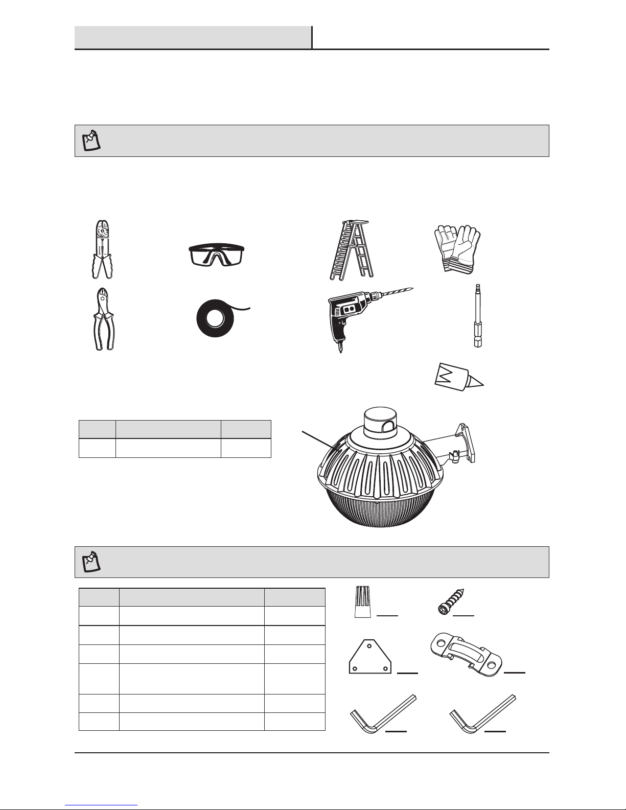
TOOLS REQUIRED
Part Description Quantity
AA Wire Connector 3
BB Hexagon Socket Mounting Screw 3
CC Mounting Template 1
DD Pole Clamp (for optional pole
mount installation only)
1
EE Allen Wrench (M6) 1
FF Allen Wrench (M8) 1
Part Description Quantity
A LED Area Light 1
PACKAGE CONTENTS
A
AA
HARDWARE INCLUDED
NOTE: Hardware not shown to actual size.
BB
DD
CC
EE FF
Wire
Strippers
Electrical
Tape
Wire
Cutters
Safety
Goggles
Ladder
Gloves
Power Drill
with Drill BIts
Power Tool
Hex Bit
Silicone
Sealant
4
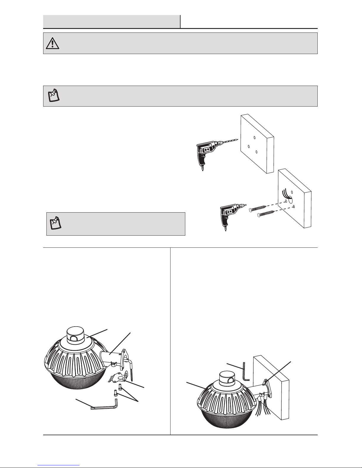
Installation
1
Attaching the mounting screws
to the wall
For new installation:
□ Mark the hole locations on the wall using the
included template (CC).
□ Drill 3/16 in. diameter pilot holes at the marked
locations, ensuring that the two screw positions at
the bottom are level with each other.
For replacement installation or for new installation:
□ Install two hexagon socket mounting screws (BB) in
the bottom holes, leaving about 3/8 in. space under
the head.
NOTE: Hardware included is for mounting to wood surfaces
only. Ensure that the fixture is mounted onto a structurally
sound surface that will support the fixture.
2
Preparing the fixture for
mounting
□ Remove the wire cover from the fixture
arm on the area light (A) using the M8
allen wrench (FF).
□ Put the wire cover screws aside until
ready for reassembly in a later step.
3
Mounting the light fixture
□ Slide the mounting bracket on the fixture arm of the
area light (A) onto the two bottom hexagon socket
mounting screws (BB) inserted in the wall.
□ Install the third hexagon socket mounting screw
(BB) at the top of the mounting bracket and tighten
securely using the M6 allen wrench (EE).
□ Tighten the two hexagon socket mounting screws
(BB) at the bottom of the mounting bracket on the
fixture arm with the M6 allen wrench (EE).
WARNING: RISK OF ELECTRIC SHOCK. Ensure the electricity to the wires you are working on is shut off. Either remove the fuse or turn off
the circuit breaker before removing the existing light fixture or installing the new one.
With power disconnected to the electrical box, remove the existing fixture. Make a sketch of how the current
fixture is wired (by wire color) or mark the wires with masking tape and a pencil so you will know how to properly
reconnect the wires to the new LED light fixture.
NOTE: Recommended installation height is 3.9 ft. or above.
Wire cover
screws
FF
A
Wire
cover
Fixture
arm
A
Mounting
bracket
EE
5 HOMEDEPOT.COM
Please contact 1-866-308-3976 for further assistance.
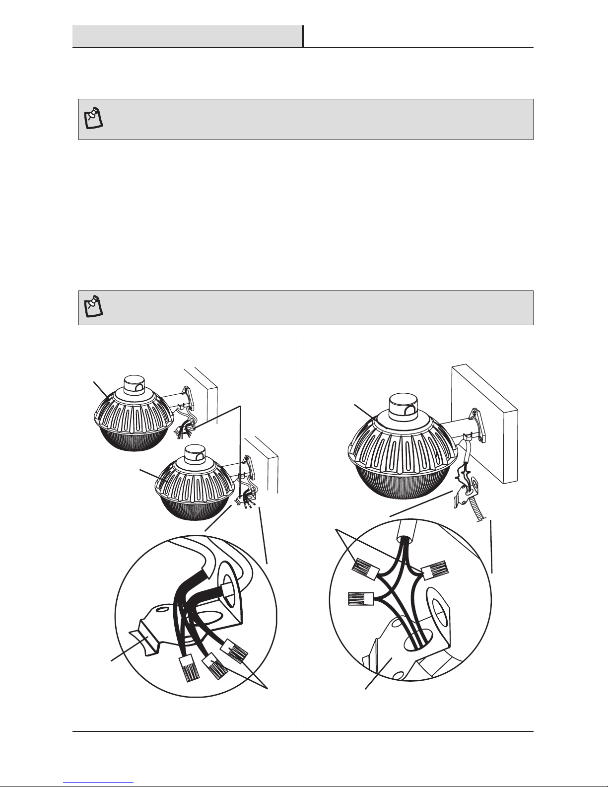
Option A Option B
4
Making the electrical connections
NOTE: This fixture is intended for use with an electrical box, conduit, and conduit connectors that are UL rated for wet locations and are
properly installed and grounded.
□ For electrical wires coming from the wall at the position of the fixture, feed the wires from the wall through
the vertical opening on the end of the wire cover. See Option A drawing below.
□ For electrical wires running through conduit or a raceway from an electrical box mounted to the wall, feed
the wires through the horizontal opening in the bottom of the wire cover. See Option B drawing below.
□ Connect the hot and neutral (black and white) wires from the fixture arm on the area light (A) to the same
color wires from the electrical box in the wall.
□ Connect the green wire from the fixture arm on the area light (A) to the grounding wire from the electrical
box in the wall.
□ Cover the wire connections using the wire connectors (AA).
□ Wrap the wire connectors (AA) with electrical tape for a more secure connection.
NOTE: If electrical box wiring does not include a ground wire, consult your local electrical code for approved grounding methods.
A
A
AA
Wire
cover
Wire
cover
A
AA
Installation (continued)
Wire
cover
6
Option A Option B
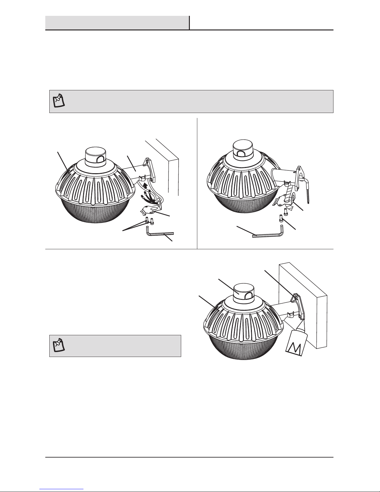
6
Restoring power
□ Restore power at the electrical panel.
□ Turn on the light switch to activate the
fixture.
□ Seal the area where the mounting bracket
on the area light (A) meets the wall with
silicone sealant.
NOTE: Test fixture at night or block the photocell to
determine if the fixture is lighting properly.
A
Mounting
bracket
Photocell
sensor
5
Reinstalling the wire cover
□ Insert the wires and wire connectors into the fixture arm on the area light (A).
□ Reattach the wire cover to the fixture arm on the area light (A) with the wire cover screws removed earlier
using the M8 allen wrench (FF).
NOTE: Compatible with 1-5/8 in. mounting pole (available for purchase separately). For pole installation, use the pole clamp (DD) instead
of the wire cover.
Wire cover
screws
Wire
cover
A
Fixture
arm
Installation (continued)
Wire cover
screws
Wire
cover
FF
FF
 Loading...