

Defiant 13257, 1001-475-623 Use And Care Manual
Use and Care Guide
Indoor Digital Timer
IP07232014 HOMEDEPOT.com
Please contact 1-866-308-3976 for further assistance.
Item #1001-475-623
Model #13257
UPC #030878132572
Before You Begin
Product Information
□ Set one or multiple ON/OFF settings for each day of the week, daily cycles, or weekday - weekend
cycles
□ Stores up to 18 individual programs - 9 on/off programs.
□ Controls incandescent lights, fluorescent lights, LED lights, or horsepower loads such as a motor for
small fans
Pre-Installation Requirements
This timer requires that your switch box have a neutral wire in order for the timer to operate correctly.
□ This timer will work in a single pole installation. It will not work in a 4-way or 3-way installation.
□ This timer will only work on loads up to 15 amps resistive or 10 amps tungsten.
Safety Information
WARNING
RISK OF ELECTRIC SHOCK:
Shut off the power at the fuse box or circuit breaker before installation
Do not use in wet locations
Use indoors only
RISK OF ELECTRIC FIRE:
Do not use to control appliances that contain heating elements such as cooking appliances,
heaters, and irons
Do not exceed electrical ratings
Do not use to control receptacles
Use only copper wire with this device
WARNING: This device is intended for installation in accordance with the National Electric Code and local
regulations in the United States, or the Canadian Electrical Code and local regulations in Canada. if you are
unsure or uncomfortable about performing this installation, consult a qualied electrician.
Product Specications
□ Single pole installation only.
RATINGS
120 VAC, 60Hz
15A, 1800W Resistive 1200W Tungsten 1/2 HP Motor
Hardware Included
AA - Wire Nut x4
BB - Screw x2
Suggested Tools
Phillips screwdriver
Wire strippers
Warranty
The manufacturer warrants this product to be free from manufacturing defects for a period of
one year from the original date of consumer purchase. This warranty is limited to the repair or
replacement of this product only and does not extend to consequential or incidental damage to
other products that may be used with this product. This warranty is in lieu of all other warranties,
expressed or implied. Some states do not allow limitations on how long an implied warranty lasts
or permit the exclusion or limitation of incidental or consequential damage, so the above limitations
may not apply to you. This warranty gives you specic rights, and you may also have other rights
which vary from state to state.
Contact Home Depot customer service at 1-866-308-3976 or visit www.homedepot.com for more
information.
FCC NOTE
This device complies with part 15 of the FCC and Industry Canada license-exempt RSS standard(s).
Operation is subject to the following two conditions: (1) this device may not cause harmful
interference, and (2) this device must accept any interference received, including interference that
may cause undesired operation.
FCC NOTE: The manufacturer is not responsible for any radio or TV interference caused by
unauthorized modications to this equipment. Such modications could void the user’s authority to
operate the equipment.
NOTE: This equipment has been tested and found to comply with the limits for aClass B digital
device, pursuant to Part 15 of the FCC Rules. These limits are designed to provide reasonable
protection against harmful interference in aresidential installation. This equipment generates,
uses and can radiate radio frequency energy and, if not installed and used in accordance with
theinstructions may cause harmful interference to radio communications. However, there is no
guarantee that interference will not occur in a particular installation.If this equipment does cause
harmful interference to radio or television reception, which can be determined by turning the
equipment off and on, the user isencouraged to try to correct the interference by one or more of the
following measures:
-- Reorient or relocate the receiving antenna.
-- Increase the separation between the equipment and receiver.
-- Connect the equipment into an outlet on a circuit differentfrom that to which the receiver is
connected.
Consult the dealer or an experienced radio/TV technician for help
CAN ICES-3(B)/NMB-3(B)
Installation Terms and Options
WARNING: Shut off power at the fuse box or circuit breaker before performing any wiring or installation.
BASIC WIRING TERMINOLOGY
To better familiarize yourself with the wiring terminology and concepts referenced in this
manual, please review the following information before you begin wiring this timer to your
switch outlet. If at any time during the wiring process you become uncertain, please contact a
certied electrician.
□ Line: This is the 120 VAC (hot) from breaker box.
□ Load: This is the 120 VAC wire that controls the xture (load out) which carries power to
the light.
□ Neutral: 120 VAC return connection.
□ Ground: 120 VAC safety ground.
INSTALLATION
Single-Pole Installation:
This installation option should be used when a switch only controls one outlet from a single
location. A typical example of where you would nd a single-pole switch is your bedroom or
bathroom light switch.
1 Single Pole Installation
Disconnect the power at the circuit breaker or fuse box
a. Remove the existing switch.
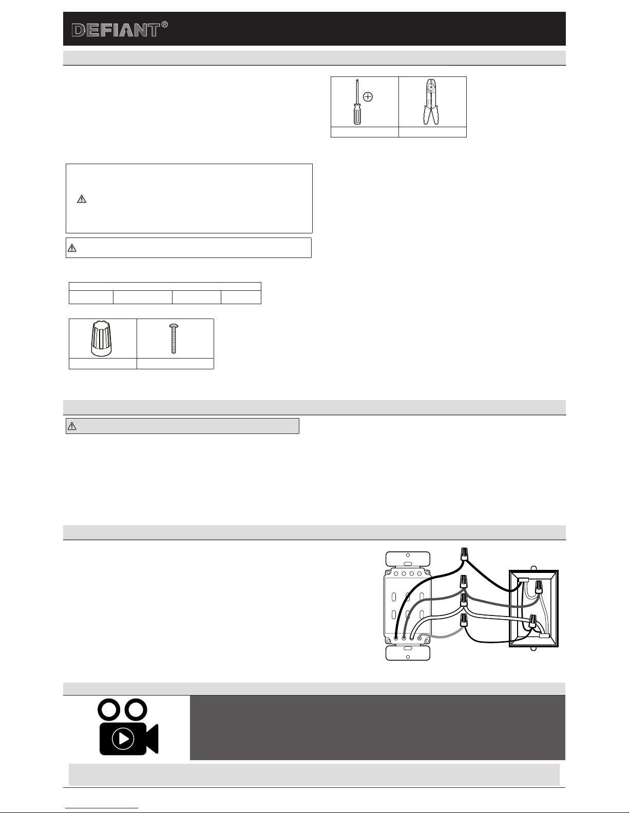
b. Connect the wires of the timer to the wall box as shown, using the wire nuts (AA) provided. See Figure 2.
□ Connect the hot/live wire of the line to the black wire from the timer.
□ Connect the hot/live wire of the load to the red wire from the timer.
□ Connect the ground wire to the green wire from the timer.
□ Connect the neutral wire to the white wire from the timer. Often the neutral (white) wire can be found in the
back of the wire box connected with a wire nut. There may be several neutral wires bound together. Add the
timer neutral to all neutral wires bound together making sure the wire nut is tight.
c. Ensure that all wire nuts are secure, and tuck the wires into the wall box, leaving room for the timer. Use the
screws (BB) to mount the timer to the wall box, being careful not to crush any wires.
d. Reinstall your wall plate.
e. Turn the main power ON at the circuit breaker.
f. Turn the slide switch (I) to the On position.
g. If the timer display does not turn on, disconnect the power at the circuit breaker or fuse box. Swap the black and
red wires on the timer. Remount the timer and wall plate, then restore power at the fuse box or circuit breaker.
Figure 2 - Connecting the Timer Wires for Single Pole Installation
GREEN
RED
WHITE
BLACK
TIMER
WALL BOX
LINE
NEUTRAL
LOAD
GROUND
Programming Instructional Video
To view an instructional video on how to program this product:
1. Go to www.homedepot.com and enter either the Item or Model number found in the top right
corner of this instruction sheet in the search field.
2. Click on your product from the list of search results and click on the video link in the Product
Overview section.
CONTINUE TO PAGE 2 TO COMPLETE SETUP AND PROGRAMMING
Use and Care Guide
Indoor Digital Timer
IP07232014 HOMEDEPOT.com
Please contact 1-866-308-3976 for further assistance.
Initial Setup
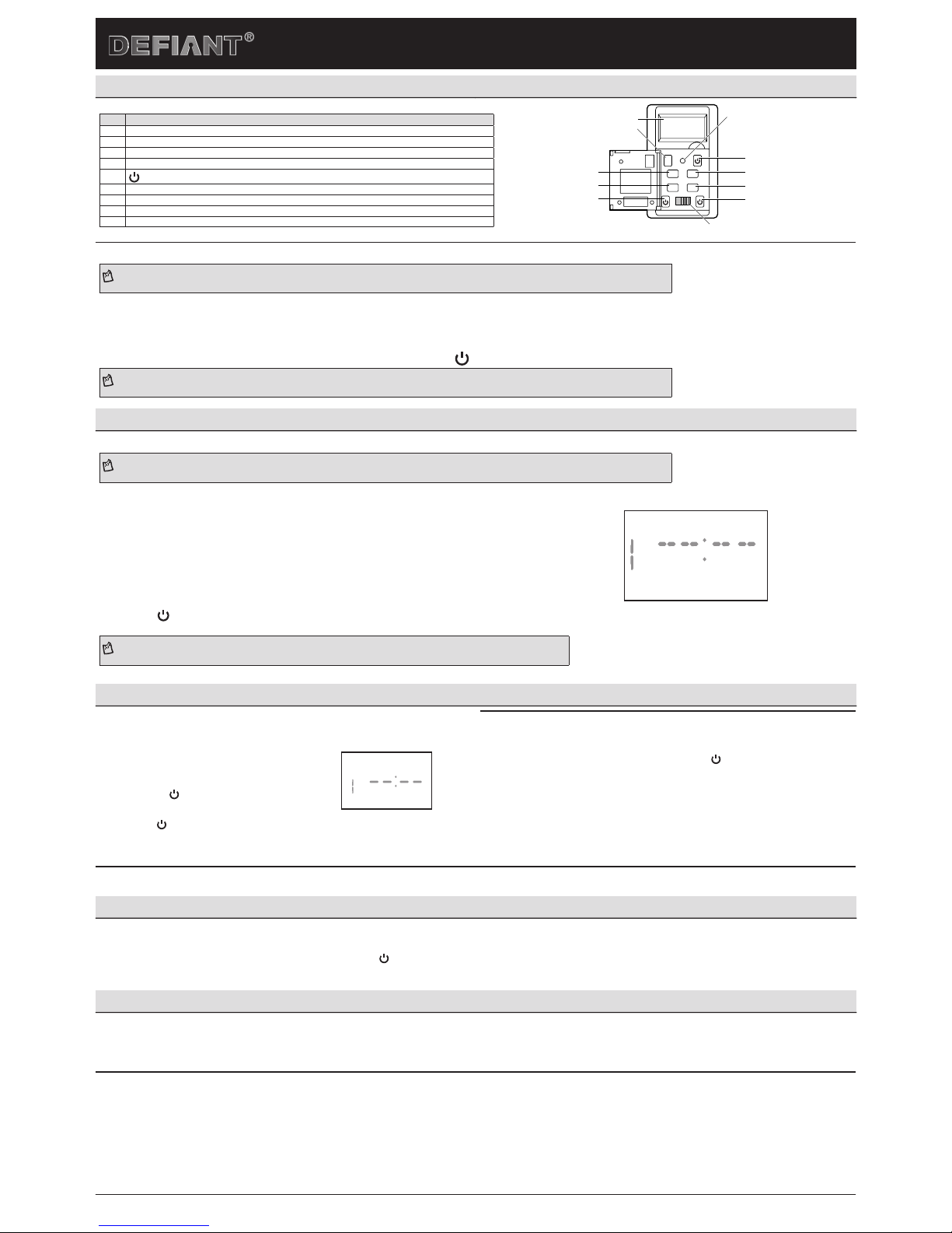
PRODUCT DESCRIPTION
Part Description
A Timer display
B Mode: Changes timer from automatic to manual mode.
C DAY: Press to set the programmed days.
D SET: Press once to set the current time. Press twice to set on/off programs.
E
: Pres to turn the lights on and off manually.
F RESET: Press to reset the timer.
G HOUR: Press to set the hour.
H MIN: Press to set the minutes.
I POWER: Slide to turn the timer ON and OFF.
R
MODE
DAY
SET
INM
OFF ON
HOUR
A
B
F
E
G
C
D
E
H
E
I
1
SETTING THE TIMER UP FOR THE FIRST TIME
NOTE: This timer will automatically return to the clock mode if a button is not pushed for 5 seconds. Push the SET button once to return to clock setting mode if this happens
a. Remove the protective lm from the screen and slide the switch to ON.
b. Using the tip of a pencil, gently press R to clear all programming and the clock.
c. Push and release the SET button to enter into clock setting mode.
d. Push the DAY button until you reach the current day of the week.
e. Push the HOUR and MIN buttons respectively until you reach the current time. Push the button when you are nished setting the current day and time.
NOTE: Be sure the AM/PM is correct when entering the current time. “A” or “P” is displayed to the right of the time on the timer display.
Programming
1
PROGRAMMING THE TIMER
NOTE: This timer will automatically return to the clock mode if a button is not pushed for 5 seconds. Push the SET button once to return to clock setting mode if this happens
a. Push and release the SET button twice to enter into programming mode.
b. Continue to press the DAY button to select the day(s) you want this program to turn the timer ON:
□ M
-Su (every day of the week)
□ Mo-Fr (weekdays)
□ Sa-Su (weekend)
□ S, M, T, W, Th, F, S (individual days)
□
c. Press the HOUR and MIN buttons respectively to set the hour and minute you want the timer to turn ON.
d. Press and release the SET button when you are nished setting the ON setting to immediately begin
setting the OFF setting.
e. Press the button when you are nished setting the OFF time to save this program. If you wish to add
additional programs (up to 18 in total), repeat this procedure on the next open program.
NOTE: Be sure the AM/PM is correct when entering your program times. “A” or “P” is displayed to the right of the time on the timer display.
PROG
ON
MO
Additional Programming Options
1
DELETING PROGRAMS
a. Press the SET button until you are at the program
you wish to delete. Press MODE and the program
will be deleted.
b. You can press the SET button again to select
another program for deletion following the steps
above. Press when you have completed
deleting all desired programs.
ON
PROG
2
SETTING TIMER TO MANUAL OR AUTO MODE
The timer has two modes. MANUAL mode will allow you to control the timer like a normal
light switch. When in MANUAL mode (shown as MAN on the Timer display) turn your
connected device On/Off by pushing the timer door or the button. AUTO mode uses the
timer programming to turn the connected device ON/OFF automatically at the set times.
□ To switch between MANUAL and AUTO modes, press the MODE button. The mode that
you are in will display on the timer screen.
c. Press the button or wait 5 seconds to return to clock mode and save your
program settings.
Additional Features
USING THE MANUAL OVERRIDE FEATURE (OPTIONAL)
Manual override with active programming: Press the timer door or the button, which will turn the lights on and off. Your programs will still be active and the override will only last until the
next scheduled program when your timer is in AUTO mode.
Troubleshooting
Lights on all day controlled by timer:
□ Check to make sure the clock time is set for the correct time of day (AM/PM).
□ Check to make sure the program times are set for the correct time of day (AM/PM).
Lights come on and off at times different than they programmed:
□ Check to see if there are multiple programs on the timer that conict with each other.
LCD display does not light:
□ Make sure the front power switch is in the “on” position.
 Loading...