

Defender Security 82-20235, 82-20240, 82-20245 User Manual

HDCVI Mini 1U DVR User’s Manual
Version 1.2.0
for model# 82-20235, 82-20240 & 82-20245

2
Table of Contents
1 FEATURES AND SPECIFICATIONS ..........................................................................9
1.1 Overview ...................................................................................................................................................................9
1.2 Features ....................................................................................................................................................................9
1.3 Specifications ..........................................................................................................................................................10
2 OVERVIEW AND CONTROLS .................................................................................. 12
2.1 Front Panel.............................................................................................................................................................12
2.2 Rear Panel .............................................................................................................................................................12
2.3 Connection Sample.............................................................................................................................................14
2.4 Mouse Control.......................................................................................................................................................15
3 INSTALLATION AND CONNECTIONS .................................................................... 16
3.1 Check Unpacked DV R .......................................................................................................................................16
3.2 About Front Panel and Rear Panel................................................................................................................16
3.3 HDD Installation....................................................................................................................................................16
3.4 Connecting Power Supply ................................................................................................................................17
3.5 Connecting Video Input and Output Devices .............................................................................................17
3.5.1 Connecting Video Input ................................................................................................................................17
3.5.2 Connecting Video Output.............................................................................................................................18

3
3.6 Connecting Audio Input & Output, Bidirectional Audio ...........................................................................18
3.6.1 Audio Input ........................................................................................................................................................18
3.6.2 Audio Output ....................................................................................................................................................18
3.7 RS485 ......................................................................................................................................................................19
3.8 Other Interfaces....................................................................................................................................................19
4 OVERVIEW OF NAVIGATION AND CONTROLS.................................................. 20
4.1 Boot up and Shutdown.......................................................................................................................................20
4.1.1 Boot up ...............................................................................................................................................................20
4.1.2 Shutdown...........................................................................................................................................................20
4.1.3 Auto Resume after Power Failure.............................................................................................................20
4.1.4 Replace Button Battery.................................................................................................................................20
4.2 Startup Wizard ......................................................................................................................................................20
4.3 Manual Record .....................................................................................................................................................23
4.3.1 Live Viewing .....................................................................................................................................................23
4.4 Right -Click Menu..................................................................................................................................................26
4.4.1 Window Switch ................................................................................................................................................26
4.4.2 PTZ Control ......................................................................................................................................................26
4.4.3 Color................................................................................................................................................................. 31
4.4.4 Search ............................................................................................................................................................. 32
4.4.5 Manual Record ............................................................................................................................................. 32

4
4.5 Navigation Bar ................................................................................................................................................... 32
4.5.1 Main Menu ..................................................................................................................................................... 33
4.5.2 Output Screen............................................................................................................................................... 33
4.5.3 Favorites ......................................................................................................................................................... 33
4.5.4 Tour .................................................................................................................................................................. 33
4.5.5 PTZ ................................................................................................................................................................... 33
4.5.6 Color................................................................................................................................................................. 33
4.5.7 Search ............................................................................................................................................................. 33
4.5.8 Alarm Status .................................................................................................................................................. 33
4.5.9 Channel Info .................................................................................................................................................. 33
4.5.10 Remote Device........................................................................................................................................ 34
4.5.11 Network...................................................................................................................................................... 34
4.5.12 HDD Manager.......................................................................................................................................... 34
4.5.13 USB Manager .......................................................................................................................................... 34
4.6 USB Device Auto Pop-up............................................................................................................................... 34
4.7 Main Menu........................................................................................................................................................... 35
4.8 Operation ............................................................................................................................................................. 35
4.8.1 Search ............................................................................................................................................................. 35
4.8.2 Backup............................................................................................................................................................. 42
4.8.3 Shut Down...................................................................................................................................................... 44
4.9 Information .......................................................................................................................................................... 44
4.9.1 System Info .................................................................................................................................................... 44
4.9.2 Event ................................................................................................................................................................ 48
4.9.3 Network ........................................................................................................................................................... 48
4.9.4 Log .................................................................................................................................................................... 50
4.10 Settin g................................................................................................................................................................... 52
4.10.1 Camera ...................................................................................................................................................... 52
4.10.2 Network...................................................................................................................................................... 61
4.10.3 Event........................................................................................................................................................... 77
4.10.4 Storage ...................................................................................................................................................... 90
4.10.5 System ....................................................................................................................................................... 101

5
5 WEB OPERATION ..................................................................................................... 117
5.1 Network Connection......................................................................................................................................... 117
5.2 Login...................................................................................................................................................................... 117
5.3 LAN Mode............................................................................................................................................................ 118
5.4 Live......................................................................................................................................................................... 119
5.5 PTZ ........................................................................................................................................................................ 120
5.6 Image .................................................................................................................................................................... 121
5.6.1 Image ............................................................................................................................................................... 121
5.7 WAN Login .......................................................................................................................................................... 122
5.8 Setup ..................................................................................................................................................................... 123
5.8.1 Camera............................................................................................................................................................ 123
5.8.2 Network ........................................................................................................................................................... 131
5.8.3 Event ................................................................................................................................................................ 146
5.8.4 Storage............................................................................................................................................................ 154
5.8.5 Setting ............................................................................................................................................................. 156
5.9 Information .......................................................................................................................................................... 168
5.9.1 Version ............................................................................................................................................................ 168
5.9.2 Log .................................................................................................................................................................... 168
5.9.3 Online User .................................................................................................................................................... 169
5.10 Playback............................................................................................................................................................... 169
5.10.1 Search Record ........................................................................................................................................ 170
5.10.2 File List....................................................................................................................................................... 170
5.10.3 Playback .................................................................................................................................................... 171
5.10.4 Download .................................................................................................................................................. 171
5.10.5 Load more................................................................................................................................................. 172

6
5.11 Alarm ..................................................................................................................................................................... 174
5.12 Log out.................................................................................................................................................................. 175
5.13 Un-install Web Control .................................................................................................................................... 176
6 PROFESSIONAL SURVEILLANCE SYSTEM ...................................................... 177
7 FAQ .............................................................................................................................. 178
APPENDIX A HDD CAPACITY CALCULATION........................................................ 183
APPENDIX B COMPATIBLE BACKUP DEVICE LIST............................................. 184
APPENDIX C COMPATIBLE CD/DVD DEVICE LIST ................................................ 190
APPENDIX D COMPATIBLE DISPLAYER LIST........................................................ 191
APPENDIX E COMPATIBLE SWITCHER LIST ......................................................... 192
APPENDIX F COMPATIBLE WIRELESS MOUSE LIST.......................................... 193

7
Welcome
Thank you for purchasing
HDCVI DVR!
This user’s manual is designed to be a reference tool for the installation and operation of your
system.
Here you can find information about this series DVR features and functions, as well as a detailed
menu tree.
Before installation and operation please read the following safeguards and warnings carefully!
Defender Security

8
Important Safeguards and Warnings
1.Electrical safety
All installation and operation here should conform to your local electrical safety codes.
The product must be grounded to reduce the risk of electric shock.
We assume no liability or responsibility for all the fires or electrical shock caused by improper
handling or installation.
2.Transportation security
Heavy stress, violent vibration or water splash are not allowed during transportation, storage and
installation.
3.Installation
Keep upwards. Handle with care.
Do not apply power to the DVR before completing installation.
Do not place objects on the DVR
4.Qualified engineers needed
All the examination and repair work should be done by the qualified service engineers.
We are not liable for any problems caused by unauthorized modifications or attempted repair.
5.Environment
The DVR should be installed in a cool, dry place away from direct sunlight, inflammable,
explosive substances and etc.
This series product shall be transported, storage and used in the specified environments.
6. Accessories
Be sure to use all the accessories recommended by manufacturer.
Before installation, please open the package and check all the components are included.
Contact your local retailer ASAP if something is broken in your package.
7. Lithium battery
Improper battery use may result in fire, explosion, or personal injury!
When replace the battery, please make sure you are using the same model!

9
1 FEATURES AND SPECIFICATIONS
1.1 Overview
This series product is an excellent digital monitor product designed for security field. It adopts embedded
Linux OS to maintain reliable operation. It is easy to use and can realize surveillance function after some
simple setups. It has various functions such as record, playback, monitor at the same time and can
guarantee audio video synchronization. This series product has advanced technology and strong
network data transmission function.
This series device adopts embedded design to achieve high security and reliability. It can work in the
local end, and at the same time, when connecting it to the professional surveillance software (PSS), it
can connect to security network to realize strong network and remote monitor function. It can realize HD
monitor without changing current cable layout
This series product can be widely used in various areas such as banking, telecommunication, electric
power, interrogation, transportation, intelligent resident zone, factory, warehouse, resources, and water
conservancy.
1.2 Features
This series product has the following features:
Real-time monitor
It has analog output port, VGA port and HDMI port. You can use monitor or displayer to realize
surveillance function.
System supports VGA/HDMI output at the same time.
Storage function
Special data format to guarantee data security and can avoid vicious data modification.
Compression format
Support multiple-channel video. An independent hardware decodes the video
signal from each channel
to maintain
video
synchronization.
Backup function
Support backup operation via USB port (such as flash disk, portable HDD, burner).
Client-end user can download the file to local HDD to backup via network.
Record playback function
Support each channel real-time record independently, and at the same time it can support search,
forward play, network monitor, record search, download and etc.
Support various playback modes: slow play, fast play, backward play and frame by frame play.
Support time title overlay so that you can view event accurate occurred time
Support specified zone enlargement.

10
Support network remote real-time monitor, remote record search and remote PTZ control.
Communication port
RS485 port can realize alarm input and PTZ control.
Standard Ethernet port can realize network access function.
PTZ control
Support PTZ decoder via RS485.
Support various decode protocols to allow the PTZ to control the speed dome.
Intelligent operation
Mouse operation function
In the menu, support copy and paste setup function
UPnP
It is to establish the mapping relationship between the LAN and the WAN via the UPnP protocol.
Slight function differences may be found due to different series.
1.3 Specifications
Network operation
Parameters 4-Ch 8-Ch 16-Ch
System Main Processor Industrial embedded micro controller
OS Embedded LINUX
Video
Parameters
Video Encode
Standard
H.264
Encode
Resolution
1080P(1~15fps)/720P/960H/D1/HD1/2CIF/CIF/QCIF
Video Frame
Rate
HDCVI:1~25f/s(PAL);1~30f/s(NTSC)
CVBS:1~25f/s(PAL);1~30f/s(NTSC)
Video Frame
Rate
2048Kbps-4096Kbps,
For 1080P/720P: default setup is 2Mbps,max supports 4Mbps.
For 960H: default setup is 1Mbps,max supports 3Mbps.
Bit Stream Type Video stream/composite stream
Dual-Stream Support
Audio
Parameters
Encode
Standard
G.711A/G.711U/PCM
Audio Sampling
Rate
8KHz,16Bit
Audio Bit Rate 64Kbps

11
Video Port Analog Video
Input
4-channel,BNC port 8-channel,BNC port 16-channel,
BNC port
Network Video
Input
Max 2-channel IPC connections (8M)
Video Output
1-channel VGA output,
1-channel HDMI output (of the same video source),
HDMI/ VGA video output at the same time.
Loop Output N/A
Matrix Output N/A
Audio Port Audio Input 1-channel RCA port.
Audio Output 1-channel RCA port.
Bidirectional
Talk Input
Reuse the audio input/output port.
Parameters 4-Ch 8-Ch 16-Ch
Record Record Mode Schedule record/manual record/MD record/Alarm record
Record
Playback
Max 4-channel
playback
Max 8-channel
playback
Max 16-channel
playback
Backup Mode HDD, burner, USB device, network backup
Alarm Alarm Input N/A
Alarm Output N/A
HDD HDD Port
1 SATA port,does not support eSATA port
One HDD
Space
4T
Coomunication
Port
Network 1 RJ45 port, 100Mbps Ethernet port
Communication RS485 port
USB 2 USB ports
Others Power DC12V
Power
Consuption
≤15W(With power adapeter, no HDD)
Working
Temperature
-10℃-+55℃
Working
Humidity
10%~90%
Dimensions
Mini 1U case,325mm(W)×245mm(D)×45mm(H)
Weight
1.25KG(No HDD)
Installation
Mode
Desk
12
2 Overview and Controls
This section provides information about front panel and rear panel. When you install this series DVR for
the first time, please refer to this part first.
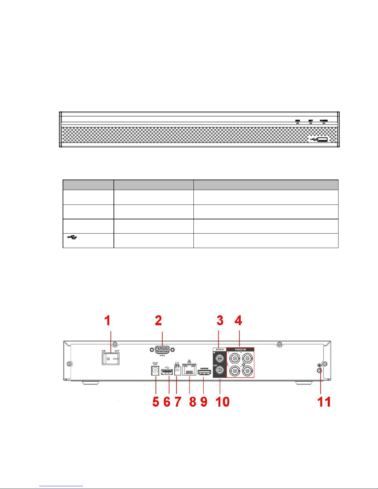
2.1 Front Panel
Figure 2-4
Please refer to the following sheet for front panel button information.
Icon Name Function
HDD HDD status indicator
light
The blue light is on when the HDD is malfunction.
NET Network status indicator
light
The blue light is on when the network connection is
abnormal.
POWER Power status indicator light The blue light is on when the power connection is
OK.
USB2.0 port Connect to peripheral USB 2.0 storage device,
mouse, burner and etc.
The 4-channel
82-20235
rear panel is shown as below. See Figure 2-38.
2.2 Rear Panel
Figure 2-38
13
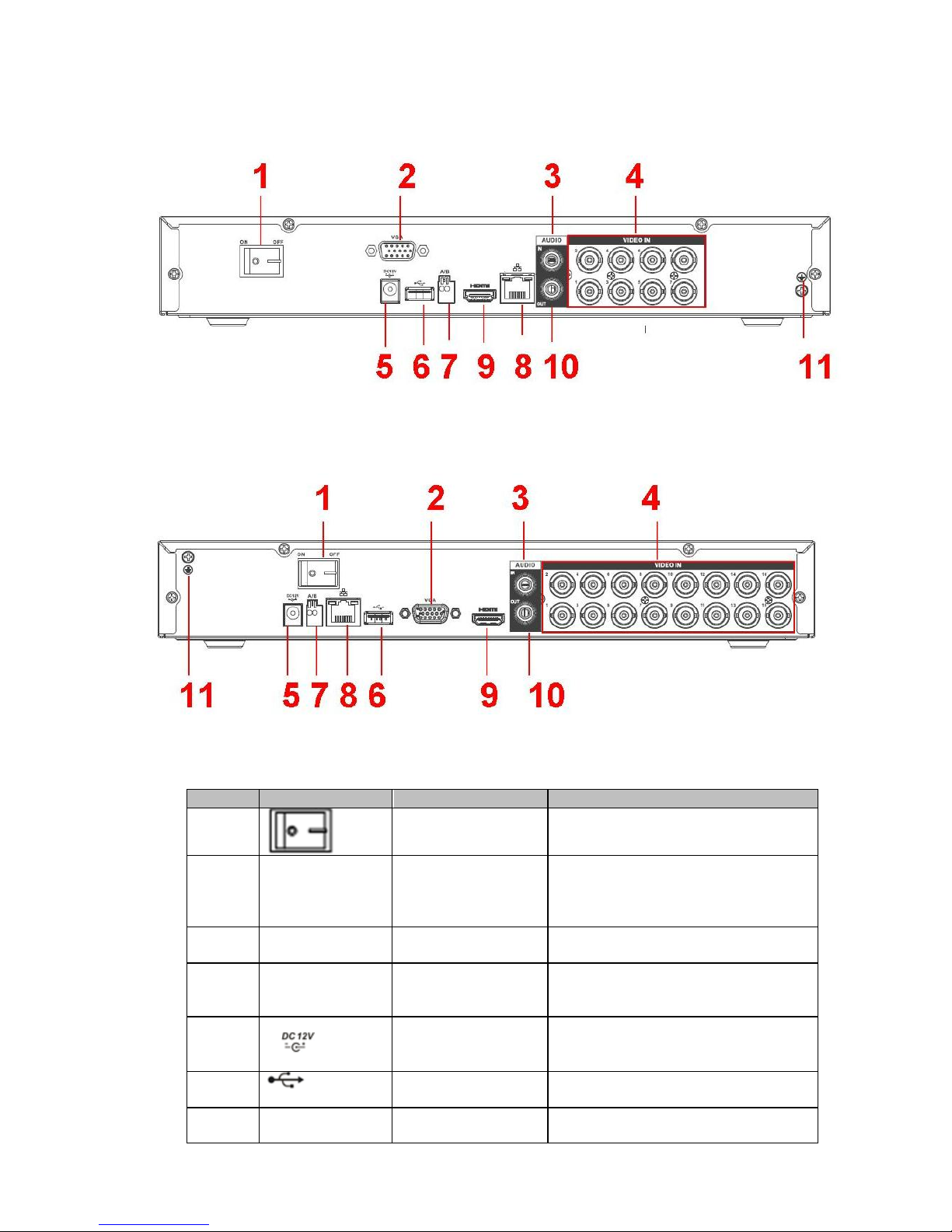
The 8-channel 82-20240 rear panel is shown as below. See
Figure
2-39.
Figure 2-39
The 16-channel 82-20245 rear panel is shown as below. See
Figure 2-40.
Figure 2-40
Please refer to the following sheet for detailed information.
SN Icon Name Note
1
Power on-off button Power on/off button.
2 VGA VGA video output
port
VGA video output port. Output
analog video signal. Can connect to
the monitor to view ananlog video
output.
3 AUDIO IN Audio input port Connect to audio input device such
as speaker.
4 VIDEO IN Video input port Connect to analog camera, video
input signal.
5
Power input port Input 12V DC.
6
USB2.0 port Connect to USB storage device,
mouse, burning DVD-ROM and etc.
7 A
RS485(RS-485)
RS485_A port. It is the cable A. You
can connect to the control devices
14
communication port such as speed dome PTZ.
B RS485_B.It is the cable B. You can
connect to the control devices such
as speed dome PTZ.
8
Network port
100M Ethernet port
9 HDMI High definition
media interface
High definition audio and video
signal output port. It transmits
uncompressed high definition video
and multiple-channel data to the
HDMI port of the display device.
10 AUDIO OUT Audio output port Connect to video output device such
as sound box.
11
GND Ground end
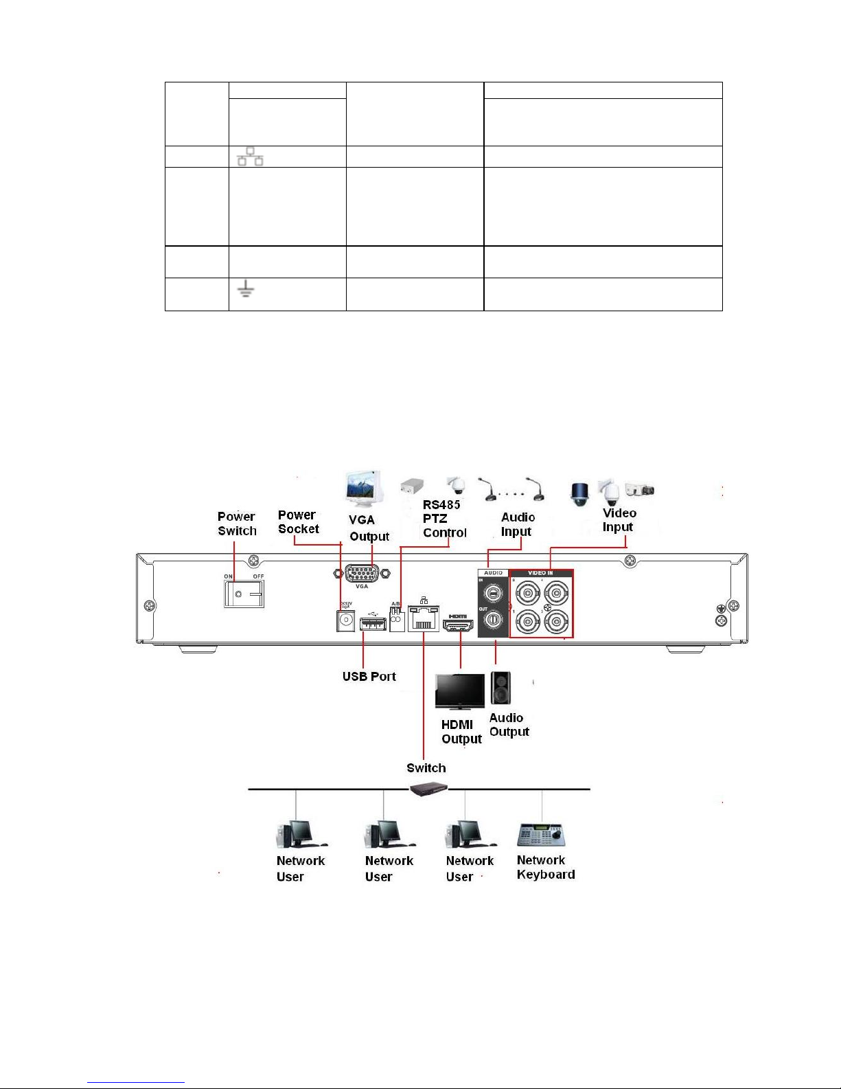
The following figure is based on the 4-channel 82-20235
2.3 Connection Sample
15
2.4 Mouse Control
Left click
mouse
System pops up password input dialogue box if you have not logged in.
In real-time monitor mode, you can go to the main menu.
When you have selected one menu item, left click mouse to view menu
content.
Implement the control operation.
Modify checkbox or motion detection status.
Click combo box to pop up drop down list
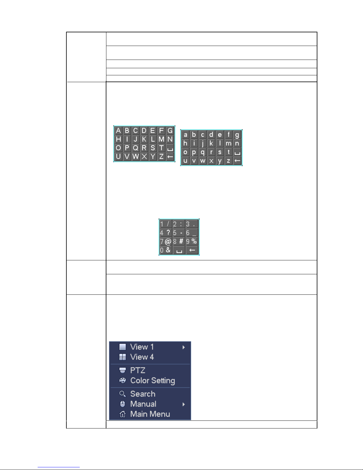
In input box, you can select input methods. Left click the corresponding button
on the panel you can input numeral/English character (small/capitalized). Here
← stands for backspace button. _ stands for space button.
In English input mode: _stands for input a backspace icon and ← stands for
deleting the previous character.
In numeral input mode: _ stands for clear and ← stands for deleting the
previous numeral.
When input special sign, you can click corresponding numeral in the front
panel to input. For example, click numeral 1 you can input“/” , or you can click
the numeral in the on-screen keyboard directly.
Double left
click mouse
Implement special control operation such as double click one item in the file list
to playback the video.
In multiple-window mode, double left click one channel to view in full-window.
Double left click current video again to go back to previous multiple-window
mode.
Right click
mouse
In real-time monitor mode, pops up shortcut menu: one-window, four-window,
nine-window and sixteen-window, Pan/Tilt/Zoom, color setting, search, record,
alarm input, alarm output, main menu.
Among which, Pan/Tilt/Zoom and color setting applies for current selected
channel.
If you are in multiple-window mode, system automatically switches to the
corresponding channel.
Exit current menu without saving the modification.
16
Press
middle
button
In numeral input box: Increase or decrease numeral value.
Switch the items in the check box.
Page up or page down
Move mouse Select current control or move control
Drag mouse Select motion detection zone
Select privacy mask zone.
3 Installation and Connections
Note: All the installation and operations here should conform to your local electric
safety rules.
3.1 Check Unpacked DVR
When you receive the DVR from the forwarding agent, please check whether there is any visible
damage. The protective materials used for the package of the DVR can protect most accidental clashes
during transportation. Then you can open the box to check the accessories.
Please check the items in accordance with the list. Finally you can remove the protective film of the DVR.
3.2 About Front Panel and Rear Panel
The model label in the front panel is very important; please check according to your purchase order.
The label in the rear panel is very important too. Usually we need you to represent the serial number
when we provide the service after sales.
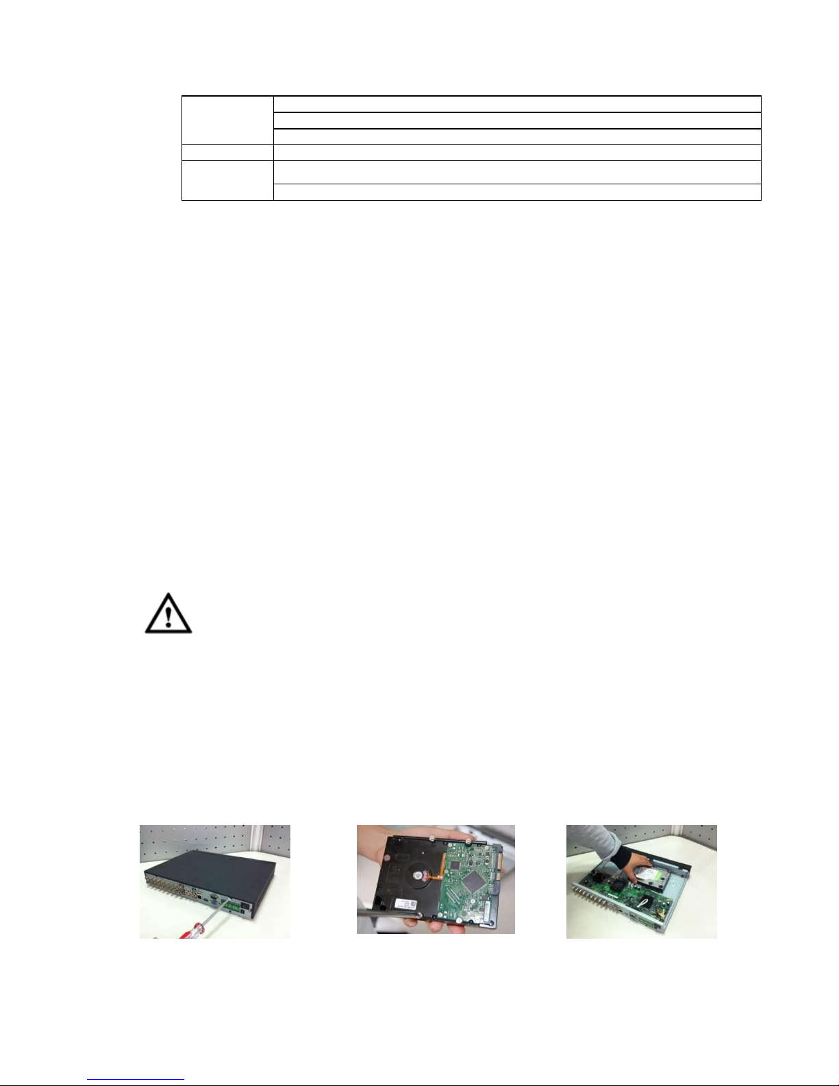
3.3 HDD Installation
Important
Shut down the device and then unplug the power cable before you open the case to
replace the HDD!
All figures listed below for reference only!
You can refer to the Appendix for recommended HDD brand. Please use HDD of 7200rpm or higher.
Please follow the instructions below to install hard disk.
The series DVR has one SATA HDD.
① Loosen the screws of the upper
cover and side panel.
②Fix four screws in the HDD (Turn
just three rounds).
③Place the HDD in accordance
with the four holes in the bottom.
17
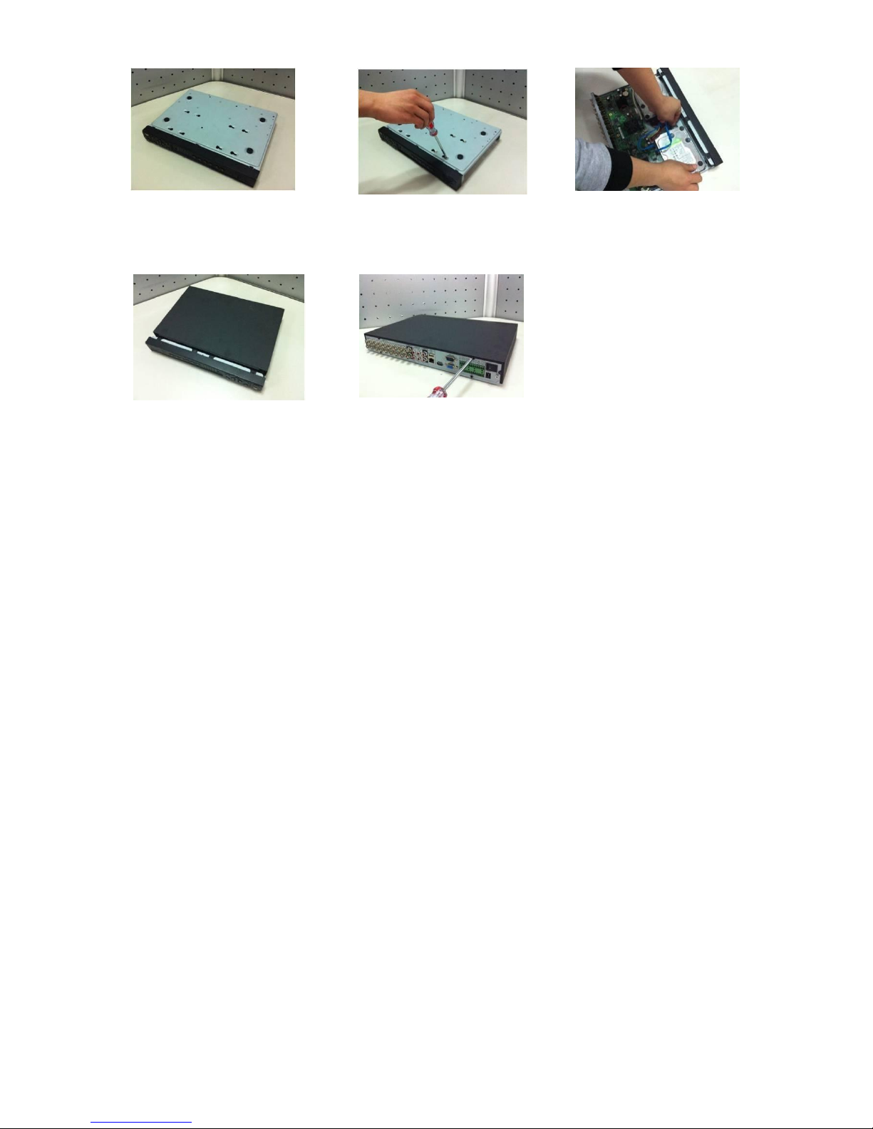
④ Turn the device upside down and
then turn the screws in firmly.
⑤Fix the HDD firmly. ⑥Connect the HDD cable and
power cable.
⑦Put the cover in accordance with the
clip and then place the upper cover
back.
⑧Secure the screws in the rear panel
and the side panel.
Important:
You can connect the HDD data cable and the power cable first and then fix the HDD in the device.
Please pay attention to the front cover. It adopts the vertical sliding design. You need to push the
clip first and then put down.
3.4 Connecting Power Supply
Please check input voltage and device power button match or not.
We recommend you use UPS to guarantee steady operation, DVR life span, and other peripheral
equipments operation such as cameras.
3.5 Connecting Video Input and Output Devices
3.5.1 Connecting Video Input
The video input interface is BNC. The input video format includes: PAL/NTSC BNC(1.0VB
P- P ,
B75Ω.)
The video signal should comply with your national standards.
The input video signal shall have high SNR, low distortion; low interference, natural color and suitable
lightness.
Guarantee the stability and reliability of the camera signal:
The camera shall be installed in a cool, dry place away from direct sunlight, inflammable, explosive
substances and etc.
The camera and the DVR should have the same grounding to ensure the normal operation of the
camera.

18
Guarantee stability and reliability of the transmission lineBTTTB
Please use high quality, sound shielded BNC. Please select suitable BNC model according to the
transmission distance.
If the distance is too long, you should use twisted pair cable, and you can add video compensation
devices or use optical fiber to ensure video quality.
You should keep the video signal away from the strong electromagnetic interference, especially the high
tension current.
Keep connection lugs in well contactBTTTB
The signal line and shielded wire should be fixed firmly and in well connection. Avoid dry joint, lap
welding and oxidation.BTTTB
3.5.2 Connecting Video Output
Video output includes
a VGA output and HDMI output
.
System
supports VGA
and HDMI
output at the same time.
When you are using pc-type monitor to replace the monitor, please pay attention to the following points:
To defer aging, do not allow the pc monitor to run for a long time.
Regular demagnetization will keep device maintain proper status.
Keep it away from strong electromagnetic interference devices.
Using TV as video output device is not a reliable substitution method. You also need to reduce the
working hour and control the interference from power supply and other devices. The low quality TV may
result in device damage.
3.6 Connecting Audio Input & Output, Bidirectional Audio
3.6.1 Audio Input
These series products audio input port adopt BNC port.
Due to high impedance of audio input, please use active sound pick-up.
Audio transmission is similar to video transmission. Try to avoid interference, dry joint, loose contact and
it shall be away from high tension current.
3.6.2 Audio Output
The audio output signal parameter is usually over 200mv 1KΩ (BNC or RCA). It can directly connect to
low impedance earphone, active sound box or amplifier-drive audio output device.
If the sound box and the pick-up cannot be separated spatially, it is easy to arouse squeaking. In this
case you can adopt the following measures:
Use better sound pick-up with better directing property.
Reduce the volume of the sound box.
Using more sound-absorbing materials in decoration can reduce voice echo and improve acoustics
environment.
Adjust the layout to reduce happening of the squeaking.

19
When the DVR receives a camera control command, it transmits that command up the coaxial cable to the
PTZ device. RS485 is a single-direction protocol; the PTZ device can’t return any data to the unit. To enable
the operation, connect the PTZ device to the RS485 (A,B) input on the DVR.
Since RS485 is disabled by default for each camera, you must enable the PTZ settings first. This series
DVRs support multiple protocols such as Pelco-D, Pelco-P.
To connect PTZ devices to the DVR:
1. Connect RS485 A,B on the DVR rear panel.
2. Connect the other end of the cable to the proper pins in the connector on the camera.
3. Please follow the instructions to configure a camera to enable each PTZ device on the DVR.
3.8 Other Interfaces
There are still other interfaces on the DVR, such as USB port.
3.7 RS485

20
4 Overview of Navigation and Controls
4.1 Boot up and Shutdown
4.1.1 Boot up
Before the boot up, please make sure:
The rated input voltage matches the device power on-off button. Please make sure the power wire
connection is OK. Then click the power on-off button.
Always use the stable current, if necessary UPS is a best alternative measure.
Please follow the steps listed below to boot up the device.
Connect the device to the monitor and then connect a mouse.
Connect power cable.
Click the power button at the front or rear panel and then boot up the device. After device booted up,
the system is in multiple-channel display mode by default.
4.1.2 Shutdown
Note
When you see corresponding dialogue box “System is shutting down…” Do not click power on-off
button directly.
Do not unplug the power cable or click power on-off button to shutdown device directly when device
is running (especially when it is recording.)
There are two ways for you to log out.
a) Main menu (RECOMMENDED)
From Main Menu->Shutdown, select shutdown from dropdown list.
Click OK button, you can see device shuts down.
b) From power on-off button on the rear panel.
4.1.3 Auto Resume after Power Failure
The system can automatically backup video and resume previous working status after power failure.
4.1.4 Replace Button Battery
Please make sure to use the same battery model if possible.
We recommend replace battery regularly (such as one-year) to guarantee system time accuracy.
Note:
Before replacement, please save the system setup, otherwise, you may lose the data
completely!
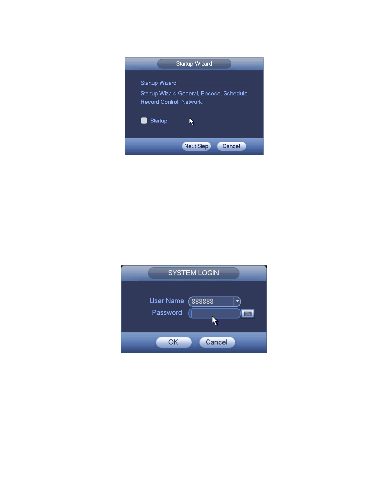
4.2 Startup Wizard
After device successfully booted up, it goes to startup wizard.
Click Cancel/Next button, you can see system goes to login interface.
Tips
21
Check the box Startup button here, system goes to startup wizard again when it boots up the next time.
Cancel the Startup button, system goes to the login interface directly when it boots up the next time.
Figure 4-1
Click Cancel button or Next Step button, system goes to login interface. See Figure 4-2.
System consists of four accounts:
Username: admin. Password: admin. (administrator, local and network)
Username: 888888. Password: 888888. (administrator, local only)
Username: 666666. Password: 666666(Lower authority user who can only monitor, playback,
backup and etc.)
Username: default. Password: default (hidden user). Hidden user “default” is for system interior
use only and can not be deleted. When there is no login user, hidden user “default” automatically
login. You can set some rights such as monitor for this user so that you can view some channel
view without login.
Figure 4-2
Note:
For security reason, please modify password after you first login.
Within 30 minutes, three times login failure will result in system alarm and five times login failure will
result in account lock!
Click OK button, you can go to General interface. See Figure 4-3.
For detailed information, please refer to chapter 4.10.5.1.
22
Figure 4-3
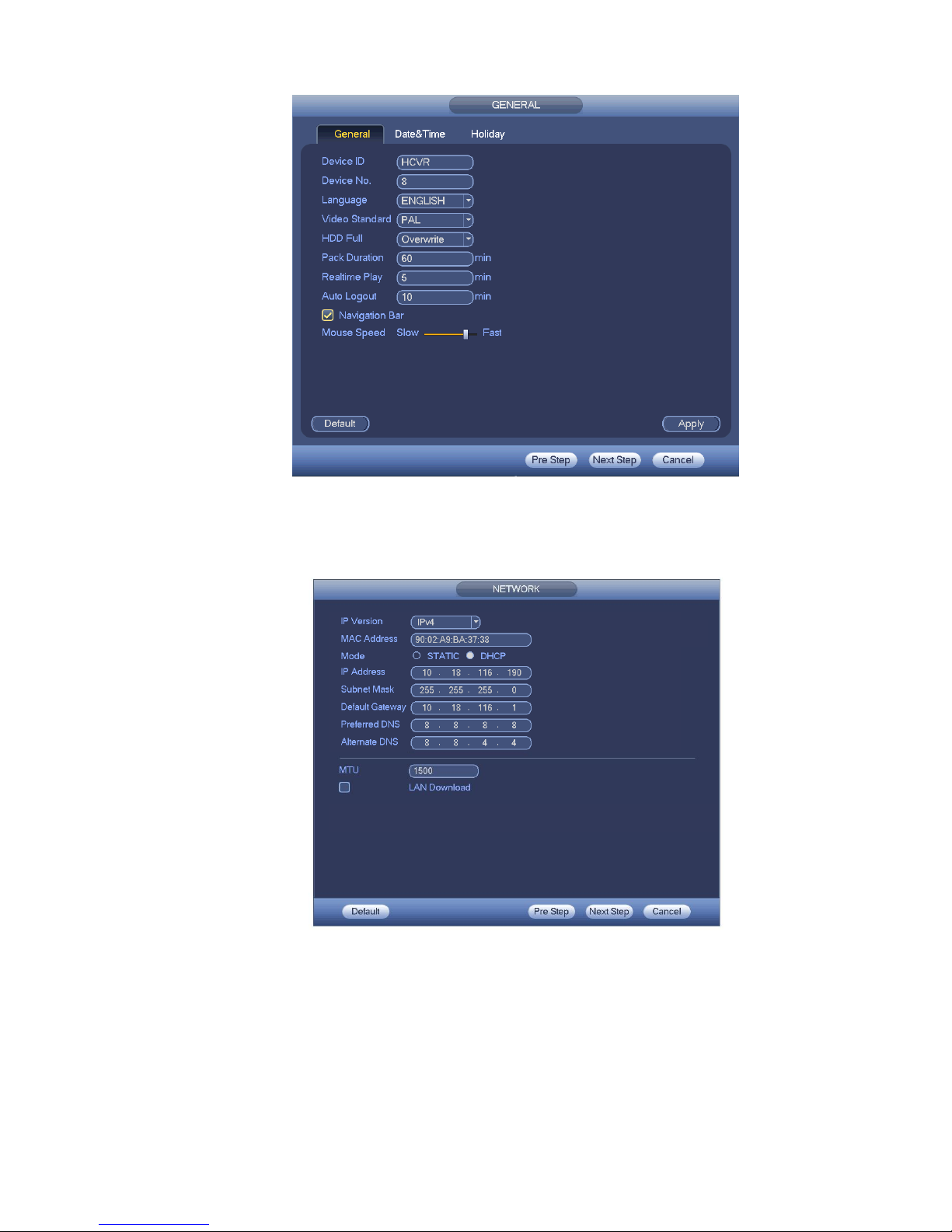
Click Next button, you can go to network interface. See Figure 4-4.
For detailed information, please refer to chapter 4.9.3.
Figure 4-4
Click Next button, you can go to Schedule interface. See Figure 4-5.
For detailed information, please refer to chapter 4.10.4.1.1.
23
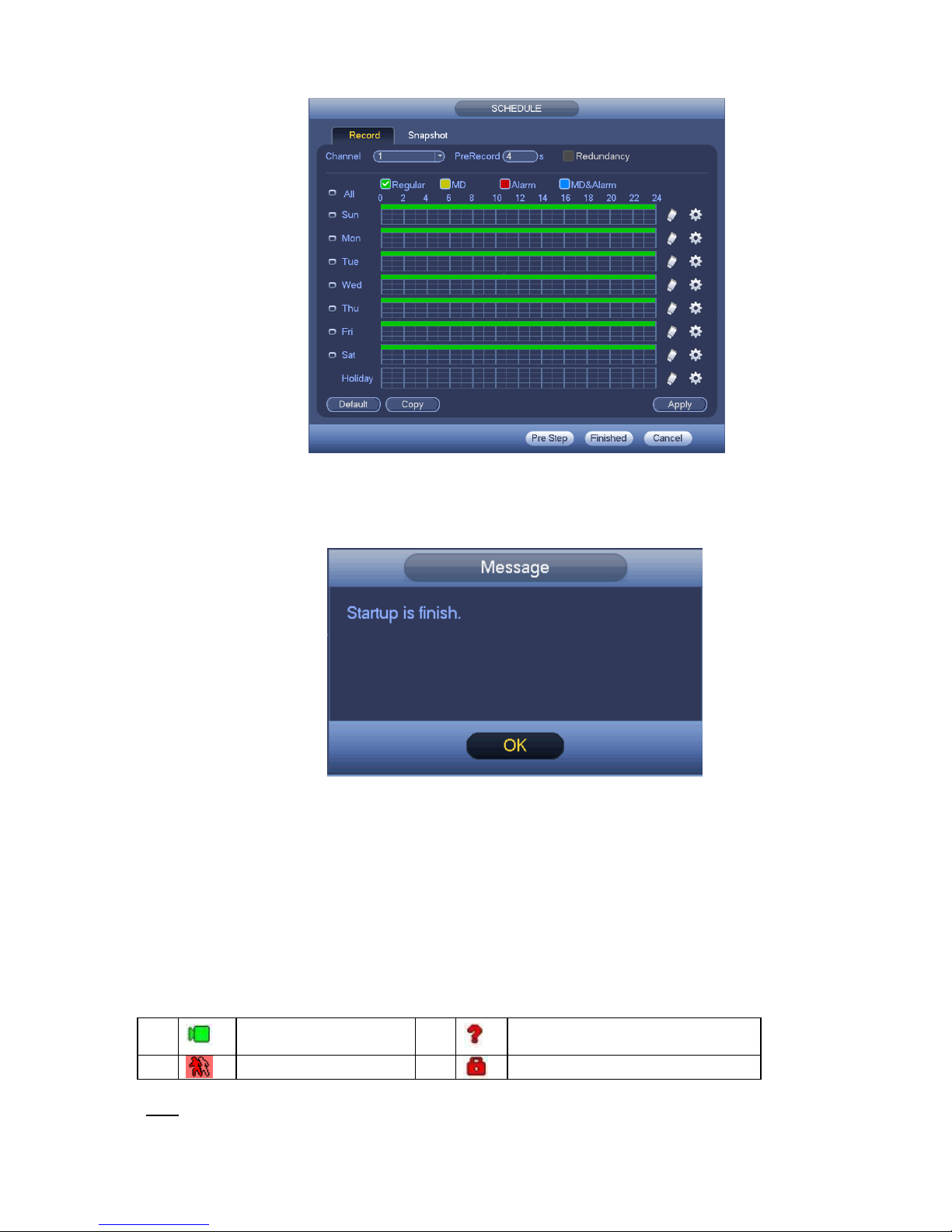
Figure 4-5
Click Finish button, system pops up a dialogue box. Click the OK button, the startup wizard is complete.
See Figure 4-6.
Figure 4-6
4.3 Manual Record
4.3.1 Live Viewing
After you logged in, the system is in live viewing mode. You can see system date, time, channel
name and window No. If you want to change system date and time, you can refer to general settings
(Main Menu->Setting->System->General). If you want to modify the channel name, please refer to
the display settings (Main Menu->Camera->CAM name).
Tips
1
Recording status 3
Video loss
2
Motion detection 4
Camera lock
24
Preview drag: If you want to change position of channel 1 and channel 2 when you are
previewing, you can left click mouse in the channel 1 and then drag to chann el 2, release
mouse you can switch channel 1 and channel 2 positions.
Use mouse middle button to control window split: You can use mouse middle button to switch
window split amount.
Preview Control
The preview control function has the following features.
Support preview playback.
In the preview desktop, system can playback previous 5-60 minutes record of current
channel. Please go to the Main Menu->General to set real-time playback time.
Support drag and play function. You can use your mouse to select any playback start time.
Support playback, pause and exit function.
Right now, system does not support slow playback and backward playback function.
Support digital zoom function.
Support real-time backup function.
You can follow the contents listed below for the operation instruction.
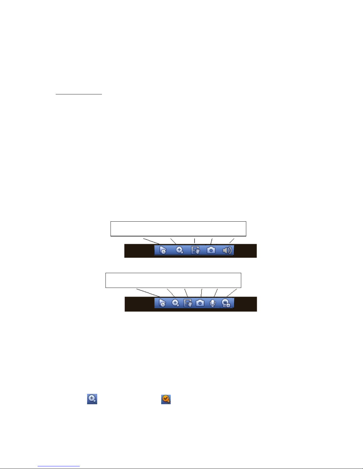
Preview control interface
Move you mouse to the top centre of the video of current channel, you can see system pops up the
preview control interface. See Figure 4-7 and Figure 4-8. If your mouse stays in this area for more
than 6 seconds and has no operation, the control bar automatically hides.
Figure 4-7 Analog Channel
Figure 4-8 Digital Channel
1) Realtime playback
It is to playback the previous 5-60 minutes record of current channel.
Please go to the Main menu->Setting->->System->General to set real-time playback time.
System may pop up a dialogue box if there is no such record in current channel.
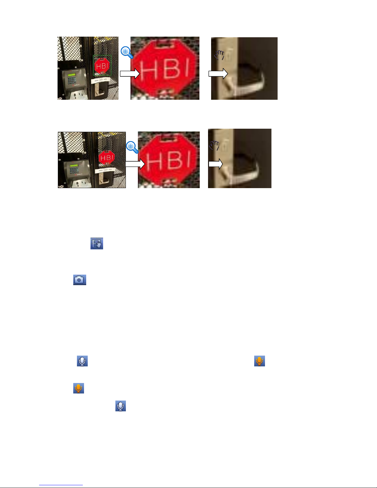
2) Digital zoom
It is to zoom in specified zone of current channel. It supports zoom in function of multiple-channel.
Click button , the button is shown as .
There are two ways for you to zoom in.
Drag the mouse to select a zone, you can view an interface show as Figure 4-9.
1 2 3 4 5
1 2 3 4 6 7
25
Figure 4-9
Put the middle button at the centre of the zone you want to zoom in, and move the mouse, you
can view an interface shown as in Figure 4-10.
Figure 4-10
Right click mouse to cancel zoom and go back to the original interface.
3) Manual record function
It is to backup the video of current channel to the USB device. System can not backup the video of
multiple-channel at the same time.
Click button , system begins recording. Click it again, system stops recoridng. You can find the
record file on the flash disk.
4) Manual Snapshot
Click to snapshot 1-5 times. The snapshot file is saved on the USB device or HDD. You can go to
the Search interface (chapter 4.8.1) to view.
5) Mute (For analog channel only)
Click to mute. Click again to enable audio function when preview.
Please note this function is for one-window mode only or the max-size window of the 8-window
mode.
6) Bidirectional talk (For digital channel only)
If the connected front-end device supports bidirectional talk function, you can click this button. Click
button to start bidirectional talk function the icon now is shown as . Now the rest
bidirectional talk buttons of digital channel becomes null too.
Click again, you can cancel bidirectional talk and the bidirectional talk buttons of other digital
channels become as .
7) Remote device (For digital channel only)
Shortcut menu. Click it to go to the remote device interface to add/delete remote device or view its
corresponding information. Please refer to chapter4.10.1.1 for detailed information.
26
4.4 Right-Click Menu
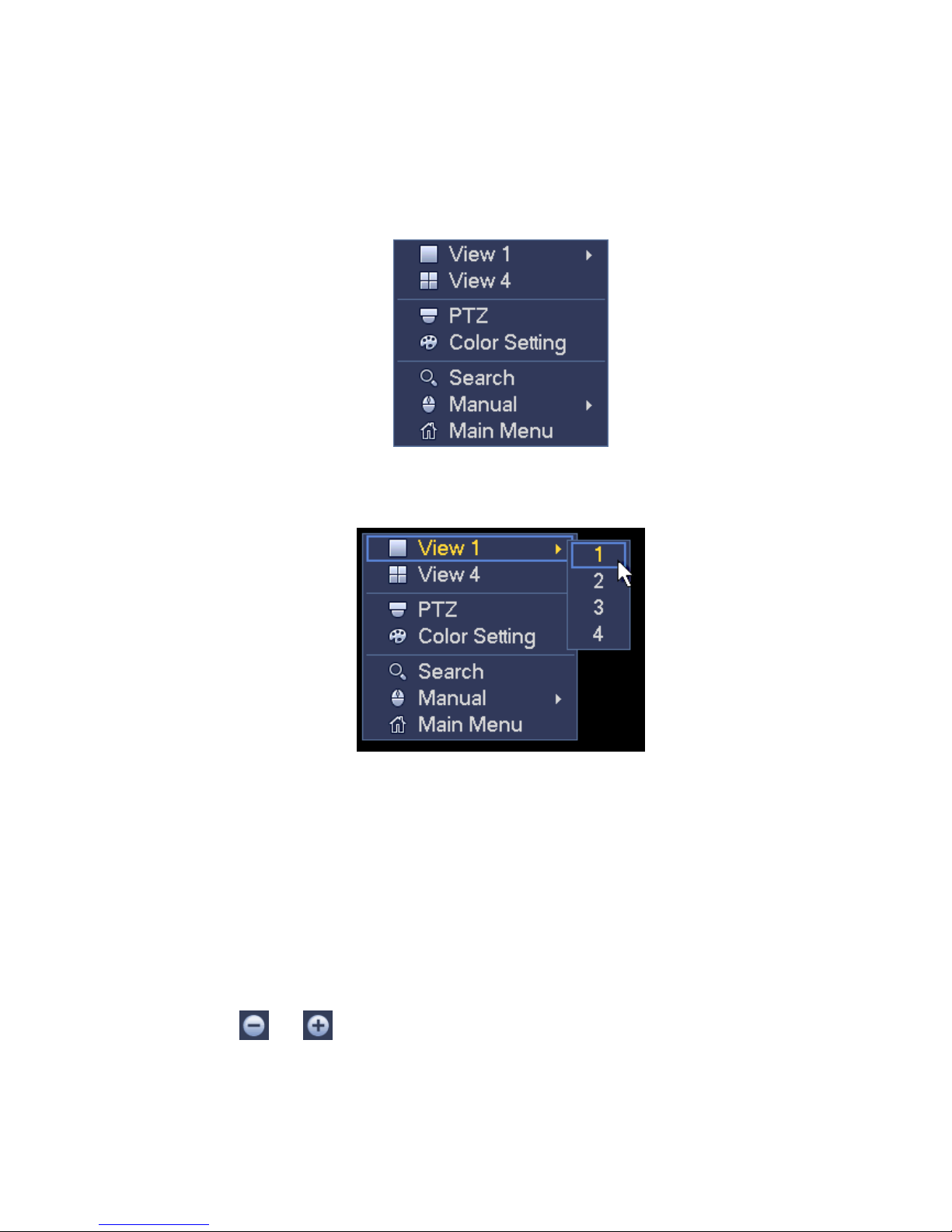
On the preview interface, right click mouse, you can view menu interface shown as in Figure 4-11.
Tips
After you go to the corresponding interface, right click mouse to go back to the upper-level.
Figure 4-11
4.4.1 Window Switch
System supports 1/4-window. You can select from the dropdown list. See Figure 4-12.
Figure 4-12
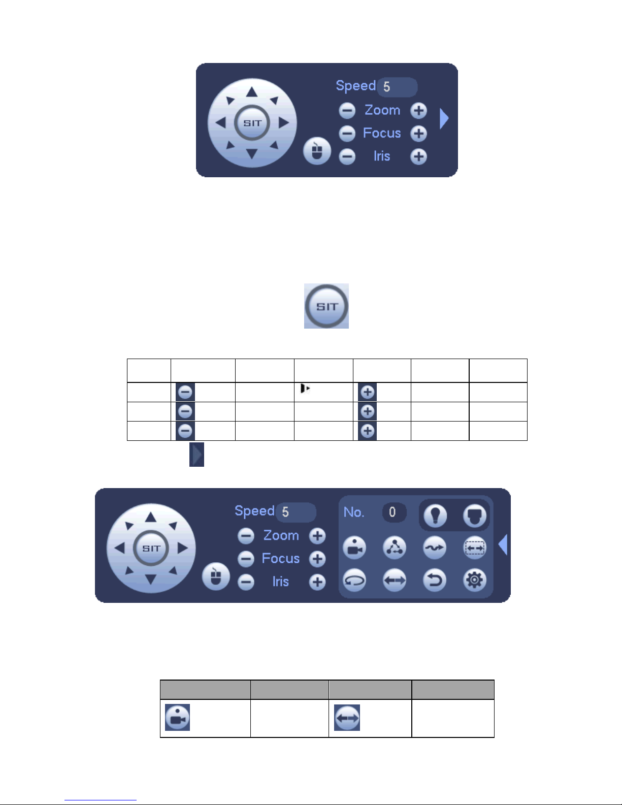
4.4.2 PTZ Control
The PTZ setup is shown as in See Figure 4-13.
Please note the commend name is grey once device does not support this function.
The PTZ operation is only valid in one-window mode.
Here you can control PTZ direction, speed, zoom, focus, iris, preset, tour, scan, pattern aux function,
light and wiper, rotation and etc.
Speed is to control PTZ movement speed. The value ranges from 1 to 8.The speed 8 is faster than
speed 1. You can use the remote control to click the small keyboard to set.
You can click and of the zoom, focus and iris to zoom in/out, definition and brightness.
The PTZ rotation supports 8 directions. If you are using direction buttons on the front panel, there are
only four directions: up/down/left/right.
27
Figure 4-13
In the middle of the eight direction arrows, there is a 3D intelligent positioning key. See Figure 4-14.
Please make sure your protocol supports this function and you need to use mouse to control.
Click this key, system goes back to the single screen mode. Drag the mouse in the screen to adjust
section size. The dragged zone supports 4X to 16X speeds. It can realize PTZ automatically. The
smaller zone you dragged, the higher the speed.
Figure 4-14
Name Function
key
function Shortcut
key
Function
key
function Shortcut
key
Zoom
Near
Far
Focus
Near │
Far ►│
Iris
close
Open
In Figure 4-13, click to open the menu, you can set preset, tour, pattern, scan and etc. See
Figure 4-15.
Figure 4-15
Please refer to the following sheet for detailed information.
Please note the above interface may vary due to different protocols. The button is grey and can not
be selected once the current function is null.
Right click mouse or click the ESC button at the front panel to go back to the Figure 4-13.
Icon Function Icon Function
Preset Flip
28
Tour Reset
Pattern Aux
Scan Aux on-off
button
Rotate Go to menu
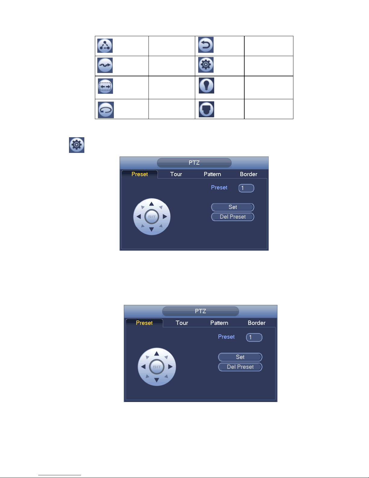
4.4.2.1 PTZ Function Setup
Click , you can go to the following interface to set preset, tour, pattern, and scan. See Figure 4-16.
Figure 4-16
Preset Setup
In Figure 4-16, click preset button and use eight direction arrows to adjust camera to the proper position.
The interface is shown as in Figure 4-17.
Click Set button and then input preset number.
Click Set button to save current preset.
Figure 4-17
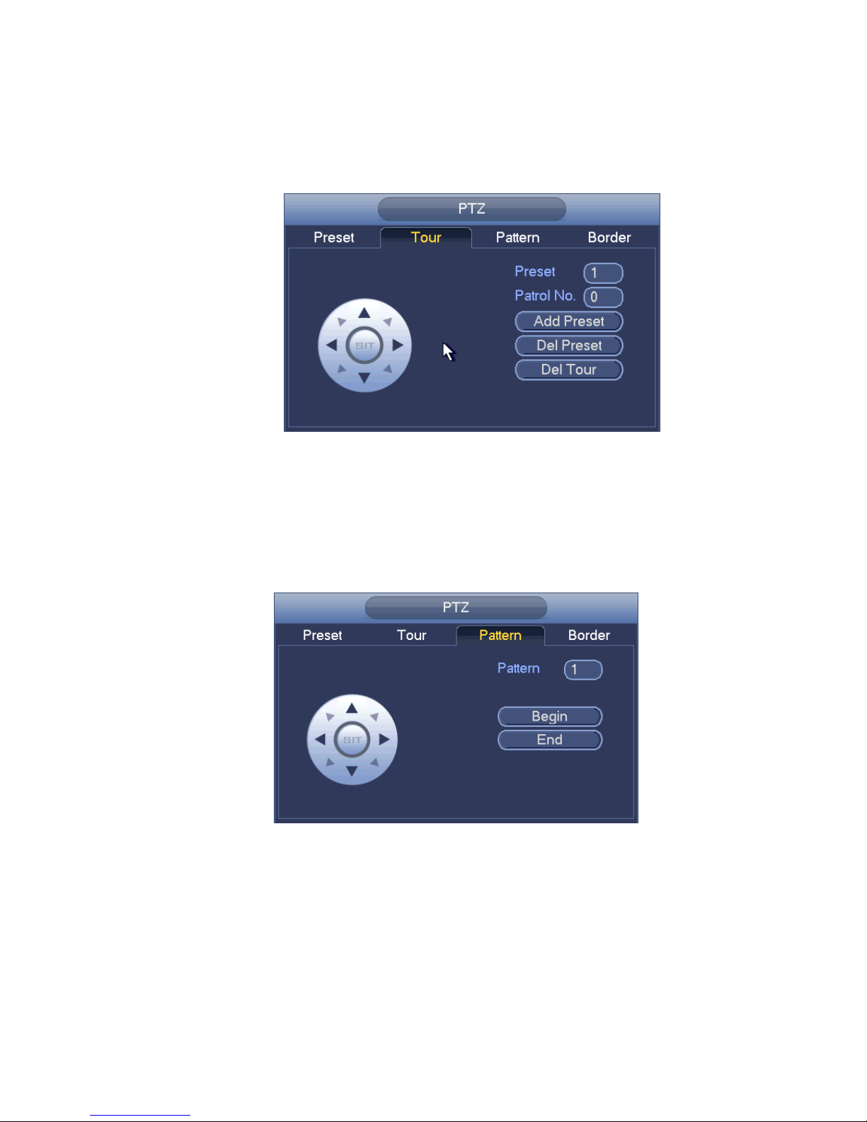
Tour Setup
In Figure 4-16, click tour button.
29
Input tour value and preset No. Click Add preset button to add current preset to the tour. See Figure
4-18.
Tips
Repeat the above steps to add more presets to the tour. Click Del preset button to remove it from the
tour. Please note some protocols do not support delete preset function.
Figure 4-18
Pattern Setup
In Figure 4-16, click Pattern button and input pattern number.
Click Begin button to start direction operation. Or you can go back to Figure 4-13 to operate
zoom/focus/iris/direction operation.
In Figure 4-16, click End button.
Figure 4-19
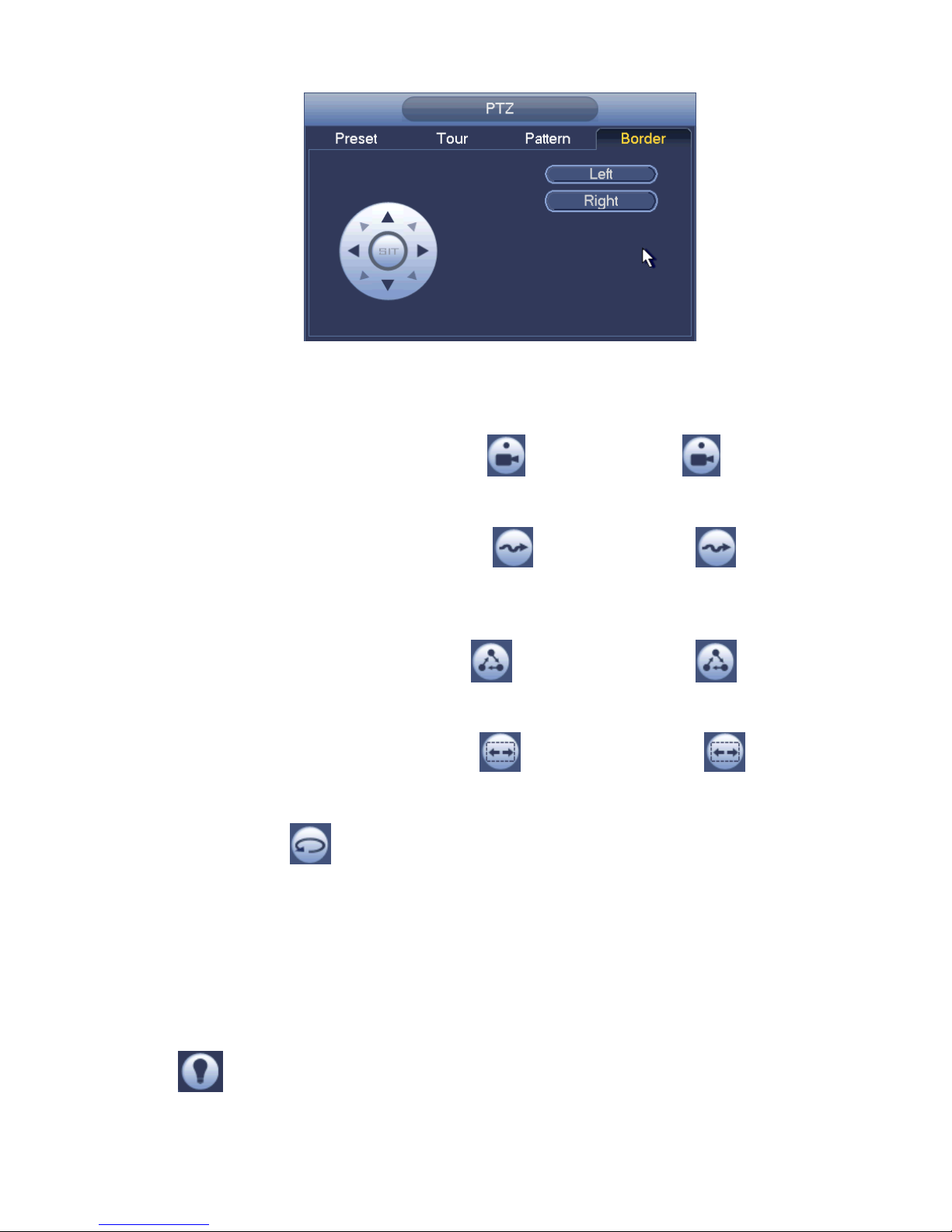
Scan Setup
In Figure 4-16, click Scan button.
Use direction buttons to set camera left limit and then click Left button.
Use direction buttons to set camera right limit and then click Right button. Now the scan setup process is
complete.
30
Figure 4-20
4.4.2.2 Call PTZ Function
Call Preset
In Figure 4-15, input preset value and then click to call a preset. Click again to stop call.
Call Pattern
In Figure 4-15, input pattern value and then click to call a pattern. Click again to stop
call.
Call Tour
In Figure 4-15, input tour value and then click to call a tour. Click again to stop call.
Call Scan
In Figure 4-15, input Scan value and then click to call a tour. Click again to stop call.
Rotate
In Figure 4-15, click to enable the camera to rotate.
System supports preset, tour, pattern, scan, rotate, light and etc function.
Note:
Preset, tour and pattern all need the value to be the control parameters. You can define it as you
require.
You need to refer to your camera user’s manual for Aux definition. In some cases, it can be used for
special process.
Aux
Click , system goes to the following interface. The options here are defined by the protocol. The
aux number is corresponding to the aux on-off button of the decoder. See Figure 4-21.
 Loading...