


High Speed PTZ Camera
82-13285


i / iii
Thank You for Choosing our PTZ Camera!
When you open the box:
Check that the packing and the contents are not visibly damaged. Contact the retailer immediately if any parts are
either missing or damaged.
Make sure if the contents are all included as per the packing list.
Do not attempt to use the device with missing or damaged parts. Send the product back in its original packing if it is
damaged.
The information contained in the document is subject to change without notice.

ii / iii
Table of Contents
1. Safety Notes --- Important!!! ..............................................................................................................................1
2. About The Product .............................................................................................................................................2
2.1. Features....................................................................................................................................................2
2.2. Functions ..................................................................................................................................................2
3. Installation...........................................................................................................................................................3
3.1. DIP Switch Setting....................................................................................................................................3
3.2. Installation...............................................................................................................................................10
3.2.1. In-ceiling Mount Installatoin .........................................................................................................10
4. Operation Guide................................................................................................................................................12
4.1. Operation At Power Up...........................................................................................................................12
4.1.1. Preset Positions Programming And Recalling.............................................................................12
4.2. Function Program Menu.........................................................................................................................13
4.2.1. SYSTEM INFORMATION............................................................................................................14
4.2.2. addr setting ..................................................................................................................................14
4.2.3. Motion ..........................................................................................................................................14
4.2.4. PATTERN ....................................................................................................................................16
4.2.5. CRUISE........................................................................................................................................17
5. Trouble Shooting.............................................................................................................................................. 18
6. Notes..................................................................................................................................................................18

1 / 19
1. SAFETY NOTES --- IMPORTANT!!!
The following important notes must be followed carefully to run the PTZ camera and respective accessories in total
safety. The camera and relative accessories are called video system in this section.
Use the instructions correctly and fully
Read all safety rules and instructions carefully before starting to run the video system.
Follow the instructions in the instruction manual. Pay attention to all warnings on the camera and in the instruction
manual. Keep the safety notes and instructions for use for future reference.
Attachments & Accessories
Do not use attachments other than those recommended in the instruction manual because this could cause risks to the
products. Only use the recommended accessories for the camera for installation and operation.
Protect the video system
To protect the camera, avoid installing and using it in direct sunlight or any source of bright light. Bright light, like that
from a spotlight, can cause dimming and blurs. A vertical line may appear on the screen. This does not indicate a
problem.
Keep it away from rain and dust. Do not touch the zoom lens with your fingers. If needed, use a soft cloth and
methylated spirit to remove traces of dust. Apply a specific cap to protect the zoom lens when the camera is not in use.
Install the camera away from video interference. The pictures could present interference if the leads are arranged near
a TV set or other device. Either move the leads or re-install the device to solve the problem.
Do not use any part of the video system near water, i.e. bathtubs, wash basins, sinks, tubs, on damp surfaces, near
swimming pools, etc. Do not insert objects of any kind through the camera openings to avoid touch live parts: fire and
electrocution risk. Do not pour any kind of liquid on the device.
A switch for performing maintenance operations on the camera must be included. Connect the camera only to the
electrical power supply shown on the ratings plate. Contact your retailer if in doubt.
Lay the power wires keeping them from being trodden on or squeezed by objects placed on top of them. Pay particular
attention to leads near plugs, screws and the product outlet.
Disconnect the power lead and the wiring to protect the camera during electrical storms or when it is left unattended
and not used for a long time. This will prevent damage to the video system in the event of lightening or electrical line
overload.
Do not overload the electrical power and the extensions to prevent the risk of fire or electrocution.
Do not place the camera near or over radiators or sources of heat. Check that the area is suitably ventilated before
installing the camera inside partially closed areas (such as recesses, bookshelves and shelves).
Do not position the camera on unsteady trolleys, stands, brackets or tables. The camera could fall and severely injury
adults and children in addition to seriously damaging the product.
Maintenance & Repairs
Always contact a qualified service technician to repair the camera (or any other part of the video system). Unauthorized
opening or removing the lids may cause fire and electrocution risk and other dangers.
Disconnect all electrical parts from the mains before cleaning.
Uses spare parts specified by the manufacturer or spare parts with equivalent characteristics when replacements
required. Unauthorized replacements can cause fires, electrical shocks and other dangers.
After any servicing intervention or repair to the video system, ask the technician to run a safety check to ensure that
everything is working safely.
Damage requiring professional assistance
Disconnect the video system from the power mains and call qualified service personnel in the following cases:
If the power lead or plug is damaged.
If liquid or foreign objects accidentally penetrate inside the device.
If the device was exposed to rain or water.
If the device was dropped, subjected to heavy shocks or if the camera packaging was damaged.
If the device performance changes considerably.

2 / 19
2. ABOUT THE PRODUCT
This integrated PTZ Dome series, with built-in DSP of high performance, can combine integreated camera and
decoders. It adopts pan-digital controlling, ensuring a flexible program. Reaching all-round and complete clearance
monitoring in the true sense, due to high-accuracy rotating system, freely and fast position and successive track
scanning.
2.1. FEATURES
360ºhorizontal rotation at maximum speed of 240º/sec.
With vertical auto flip function, reach 180°vertically successive monitoring. with maximum speed of 160º/sec.
with 256 preset positions.
Built-in OSD Menu, to change dome parameter, save or call preset, and achieve auto scan, pattern etc.
Digital design, data will not be lost while power fail.
With recovery function while turning on-the users can run it as you like.
Easy Clip installation features.
Integrated design with high reliability.
RS-485 data communication.
The speed can be adjusted automatically according to zooming times.
Auto focus lens and auto white balance, BLC function.
Multi protocol compatible (Pelco-P, Pelco-D, etc).
2.2. FUNCTIONS
Object Tracking
The camera can be manually controlled from the control system by using the controller to pan, tilt and zoom the camera
up and down, right and left to follow objects under observation.
Proportional Pan
Proportional pan automatically reduces or increases the pan and tilt speeds in proportion to the zooming times. At
telephoto zoom settings, the pan and tilt speeds will be slower for a given amount of joystick deflection then at wide
zoom settings. This keeps the image from moving too fast on the monitor when there is a large amount of zoom.
Auto Flip
When the camera tilts downward and goes just beyond the vertical angle, the camera rotates 180º. When the camera
rotates (flips), the camera starts moving upward as you continue to hold joystick in the down position. Once you let go
of the joystick after the dome rotates, joystick control returns to normal operation. The auto-flip feature is useful for
following a person who passes directly beneath the camera.
Save/Call Preset
Preset function is that dome saves current horizontal angle and title angle of pan/tilt, zoom and position parameters into
memory. When necessary dome calls these parameters and adjusts Pan/Tilt and camera to that position. User can
save and call presets easily and promptly by using keyboard controller or infrared controller. The camera supports up
to 256 presets.
Lens Control
1) Zoom control
User can adjust zoom wide or near by controller and get desired image.
2) Focus control
System defaults Auto Focus mode, that is, the lens and camera will automatically adjust the focus to get the best
image.
Focus can also be controlled manually from the controller if required. Press Focus Near or Focus Far key to manually
focus. Focus can be manual via keyboard or matrix, please refer to control keyboard or matrix operation manual for
detailed operation. When adjusting position is set with focus status, it goes back to auto focus.
The camera will NOT auto focus in the following status.
Target is not in the center of image.
Targets are in near and far at the same time.
Target is of strong light object. Such as spotlight etc.

3 / 19
Target is behind the glass with water drop or dust.
Target moves too fast.
Large area target such as wall.
Target is too dark or vague.
3) IRIS control
System defaults Auto IRIS. Camera can adjust immediately according to the alteration of back ground illumination so
that a lightness steady image can be achieved.
You may adjust IRIS by controller to get required image brightness.
You can call back Auto IRIS by controlling the joystick.
Auto Back Light Compensation
Lens has been divided to six areas for back light compensation (BLC). In a strong light background camera will auto
compensate the darker object and adjust light input from the lighter area to avoid a mass image that usually presents a
sharp contrast of brightness and darkness.
Auto White Balance
Camera can automatically adjust white balance (WB) according to the alteration of background lightness to give a true
color image.
Back Light Compensation (BLC)
If a bright backlight presents, the subjects in the picture may appear dark or as a silhouette. Backlight compensation
enhances objects in the center of the picture. The camera uses the center of the picture to adjust the IRIS.If there is a
bright light source outside this area, it will wash out to white. The camera will adjust the IRIS so that the object in the
sensitive area is properly exposed.
Day/Night Function
The IR cut filter of camera module inside the camera can be removed by sending special command, so that the camera
can change from color to mono. The picture is clear even if the illumination is as low as 0.01Lux.
This is based on the relative modules. Please refer to technical parameters.
Auto Cruise
The preset position is programmed to be recalled in sequence. This feature is called auto cruise. Up to 30 presets can
be saved in each cruise tour.
Patterns
A pattern is a saved, repeating, series of pan, tilt, zoom and preset functions that can be recalled with a command from
a controller or automatically by a programmed function (alarm action or park action or power-up action).
Auto, Random and Frame Scan
Auto Scan: Make the camera scan 360ºranging from the current position.
Random Scan: Make the camera random scan 360ºranging from the current position.
Frame Scan: This feature freezes the scene on the monitor when going to a preset. This allows for smooth transition
from one preset scene to another.
Zones Setting
A zone is a pan area, defined by a left and right limit, on the 360ºpan plane. The camera has eight zones, each with a
6-character label.
3. INSTALLATION
This section contains detailed instructions for installing the camera. These instructions assume that the installer has a
good knowledge of installation techniques and is capable of adopting safe installation methods.
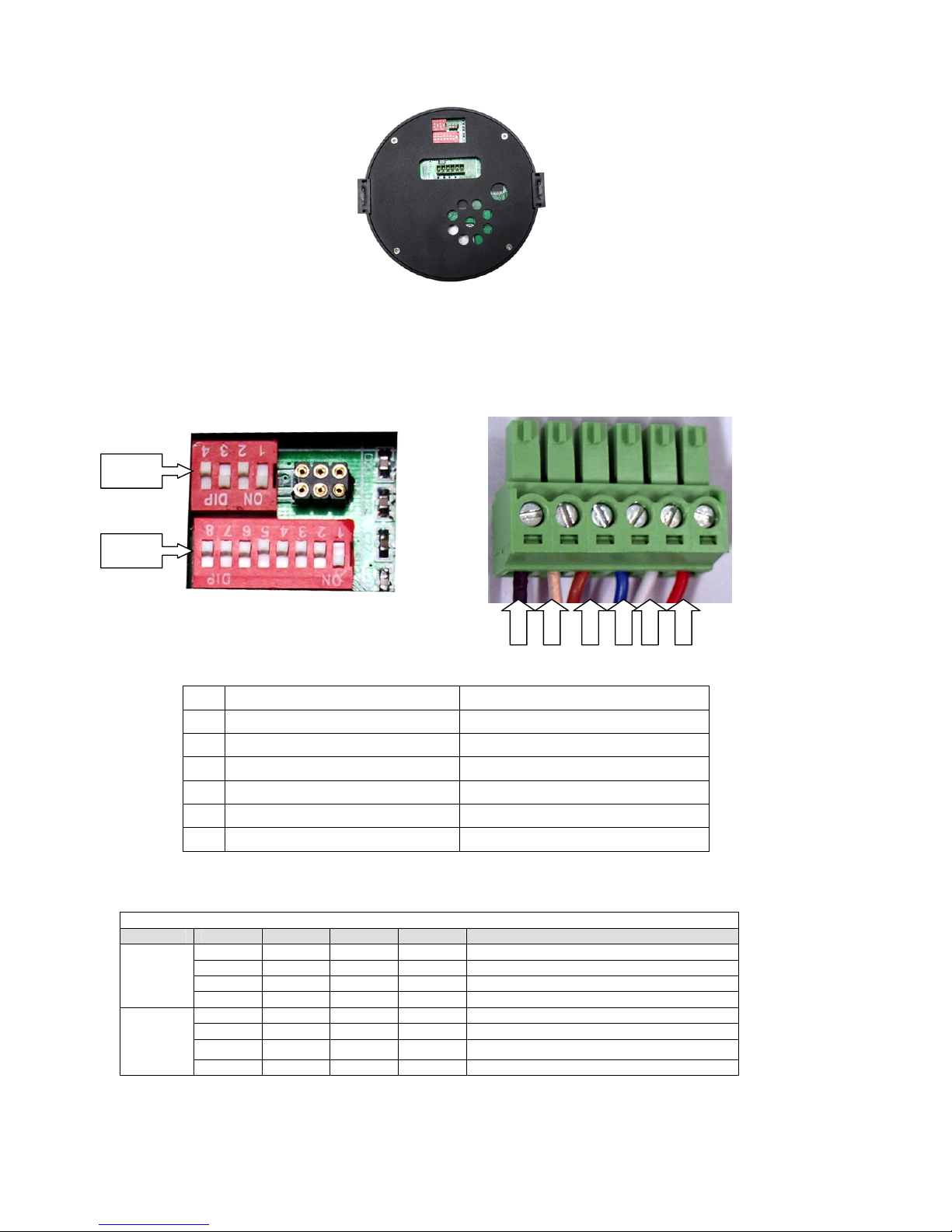
3.1. DIP SWITCH SETTING
Before installing the camera drive, check the DIP switches; configure the receiver address, communication protocol,
and baud rate setting. Pic. 1 shows switches position and default settings. SW1 switches (1and4 bit) and SW2 switches
(1 bit) are set to the ON position. For normal user, setting switches to default position is enough.
4 / 19
Pic. 1 Switch Position
The camera can be controlled via various communication protocols by setting SW1 switches(1, and 2) and operate at
1200bps, 2400bps, 4800bps, 9600bps and 19200bps baud rate by setting SW1 switches(3, and 4). Refer to Table 2:
SWITCH1 SETTING for communication protocol and baud rate settings, do not set the switches to reserved position.
Pic. 2 shows the default settings for the DIP switches. Refer to Table 3: SWITCH2 SETTING for ADDR settings.
Pic. 2 Default settings of DIP switches
NO. WIRE COLOR
1 Video- BLACK
2 Video+ GOLDEN
3 RS-485 B BROWN
4 RS-485 A BLUE
5 GND WHITE
6 DC12V()AC24V)+ RED
Table 1
Please refer to the following tables to set baud rate, and communication protocol type and camera address.
SW1
POS 1 2 3 4 DESCRIPTION
OFF OFF PELCO-P
ON OFF PELCO-D
OFF ON Reserved for future use
COMM
PTOL
OFF OFF Reserved for future use
OFF OFF AUTO
ON OFF 2400
OFF ON 4800
BAUD
RATE
(BPS)
ON ON 9600
Table 2: SWITCH1 SETTING
SW1
SW2
1 2 3 4 5 6

5 / 19
Table 3: SWITCH2 SETTING
Address 1 2 3 4 5 6 7 8
0 OFF OFF OFF OFF OFF OFF OFF OFF
1 ON OFF OFF OFF OFF OFF OFF OFF
2 OFF ON OFF OFF OFF OFF OFF OFF
3 ON ON OFF OFF OFF OFF OFF OFF
4 OFF OFF ON OFF OFF OFF OFF OFF
5 ON OFF ON OFF OFF OFF OFF OFF
6 OFF ON ON OFF OFF OFF OFF OFF
7 ON ON ON OFF OFF OFF OFF OFF
8 OFF OFF OFF ON OFF OFF OFF OFF
9 ON OFF OFF ON OFF OFF OFF OFF
10 OFF ON OFF ON OFF OFF OFF OFF
11 ON ON OFF ON OFF OFF OFF OFF
12 OFF OFF ON ON OFF OFF OFF OFF
13 ON OFF ON ON OFF OFF OFF OFF
14 OFF ON ON ON OFF OFF OFF OFF
15 ON ON ON ON OFF OFF OFF OFF
16 OFF OFF OFF OFF ON OFF OFF OFF
17 ON OFF OFF OFF ON OFF OFF OFF
18 OFF ON OFF OFF ON OFF OFF OFF
19 ON ON OFF OFF ON OFF OFF OFF
20 OFF OFF ON OFF ON OFF OFF OFF
21 ON OFF ON OFF ON OFF OFF OFF
22 OFF ON ON OFF ON OFF OFF OFF
23 ON ON ON OFF ON OFF OFF OFF
24 OFF OFF OFF ON ON OFF OFF OFF
25 ON OFF OFF ON ON OFF OFF OFF
26 OFF ON OFF ON ON OFF OFF OFF
27 ON ON OFF ON ON OFF OFF OFF
28 OFF OFF ON ON ON OFF OFF OFF
29 ON OFF ON ON ON OFF OFF OFF
30 OFF ON ON ON ON OFF OFF OFF
31 ON ON ON ON ON OFF OFF OFF
32 OFF OFF OFF OFF OFF ON OFF OFF
33 ON OFF OFF OFF OFF ON OFF OFF
34 OFF ON OFF OFF OFF ON OFF OFF
35 ON ON OFF OFF OFF ON OFF OFF
36 OFF OFF ON OFF OFF ON OFF OFF
37 ON OFF ON OFF OFF ON OFF OFF
38 OFF ON ON OFF OFF ON OFF OFF
39 ON ON ON OFF OFF ON OFF OFF
40 OFF OFF OFF ON OFF ON OFF OFF
41 ON OFF OFF ON OFF ON OFF OFF
42 OFF ON OFF ON OFF ON OFF OFF
43 ON ON OFF ON OFF ON OFF OFF
44 OFF OFF ON ON OFF ON OFF OFF
45 ON OFF ON ON OFF ON OFF OFF
46 OFF ON ON ON OFF ON OFF OFF
47 ON ON ON ON OFF ON OFF OFF
48 OFF OFF OFF OFF ON ON OFF OFF

6 / 19
49 ON OFF OFF OFF ON ON OFF OFF
50 OFF ON OFF OFF ON ON OFF OFF
51 ON ON OFF OFF ON ON OFF OFF
52 OFF OFF ON OFF ON ON OFF OFF
53 ON OFF ON OFF ON ON OFF OFF
54 OFF ON ON OFF ON ON OFF OFF
55 ON ON ON OFF ON ON OFF OFF
56 OFF OFF OFF ON ON ON OFF OFF
57 ON OFF OFF ON ON ON OFF OFF
58 OFF ON OFF ON ON ON OFF OFF
59 ON ON OFF ON ON ON OFF OFF
60 OFF OFF ON ON ON ON OFF OFF
61 ON OFF ON ON ON ON OFF OFF
62 OFF ON ON ON ON ON OFF OFF
63 ON ON ON ON ON ON OFF OFF
64 OFF OFF OFF OFF OFF OFF ON OFF
65 ON OFF OFF OFF OFF OFF ON OFF
66 OFF ON OFF OFF OFF OFF ON OFF
67 ON ON OFF OFF OFF OFF ON OFF
68 OFF OFF ON OFF OFF OFF ON OFF
69 ON OFF ON OFF OFF OFF ON OFF
70 OFF ON ON OFF OFF OFF ON OFF
71 ON ON ON OFF OFF OFF ON OFF
72 OFF OFF OFF ON OFF OFF ON OFF
73 ON OFF OFF ON OFF OFF ON OFF
74 OFF ON OFF ON OFF OFF ON OFF
75 ON ON OFF ON OFF OFF ON OFF
76 OFF OFF ON ON OFF OFF ON OFF
77 ON OFF ON ON OFF OFF ON OFF
78 OFF ON ON ON OFF OFF ON OFF
79 ON ON ON ON OFF OFF ON OFF
80 OFF OFF OFF OFF ON OFF ON OFF
81 ON OFF OFF OFF ON OFF ON OFF
82 OFF ON OFF OFF ON OFF ON OFF
83 ON ON OFF OFF ON OFF ON OFF
84 OFF OFF ON OFF ON OFF ON OFF
85 ON OFF ON OFF ON OFF ON OFF
86 OFF ON ON OFF ON OFF ON OFF
87 ON ON ON OFF ON OFF ON OFF
88 OFF OFF OFF ON ON OFF ON OFF
89 ON OFF OFF ON ON OFF ON OFF
90 OFF ON OFF ON ON OFF ON OFF
91 ON ON OFF ON ON OFF ON OFF
92 OFF OFF ON ON ON OFF ON OFF
93 ON OFF ON ON ON OFF ON OFF
94 OFF ON ON ON ON OFF ON OFF
95 ON ON ON ON ON OFF ON OFF
96 OFF OFF OFF OFF OFF ON ON OFF
97 ON OFF OFF OFF OFF ON ON OFF
98 OFF ON OFF OFF OFF ON ON OFF
99 ON ON OFF OFF OFF ON ON OFF

7 / 19
100 OFF OFF ON OFF OFF ON ON OFF
101 ON OFF ON OFF OFF ON ON OFF
102 OFF ON ON OFF OFF ON ON OFF
103 ON ON ON OFF OFF ON ON OFF
104 OFF OFF OFF ON OFF ON ON OFF
105 ON OFF OFF ON OFF ON ON OFF
106 OFF ON OFF ON OFF ON ON OFF
107 ON ON OFF ON OFF ON ON OFF
108 OFF OFF ON ON OFF ON ON OFF
109 ON OFF ON ON OFF ON ON OFF
110 OFF ON ON ON OFF ON ON OFF
111 ON ON ON ON OFF ON ON OFF
112 OFF OFF OFF OFF ON ON ON OFF
113 ON OFF OFF OFF ON ON ON OFF
114 OFF ON OFF OFF ON ON ON OFF
115 ON ON OFF OFF ON ON ON OFF
116 OFF OFF ON OFF ON ON ON OFF
117 ON OFF ON OFF ON ON ON OFF
118 OFF ON ON OFF ON ON ON OFF
119 ON ON ON OFF ON ON ON OFF
120 OFF OFF OFF ON ON ON ON OFF
121 ON OFF OFF ON ON ON ON OFF
122 OFF ON OFF ON ON ON ON OFF
123 ON ON OFF ON ON ON ON OFF
124 OFF OFF ON ON ON ON ON OFF
125 ON OFF ON ON ON ON ON OFF
126 OFF ON ON ON ON ON ON OFF
127 ON ON ON ON ON ON ON OFF
128 OFF OFF OFF OFF OFF OFF OFF ON
129 ON OFF OFF OFF OFF OFF OFF ON
130 OFF ON OFF OFF OFF OFF OFF ON
131 ON ON OFF OFF OFF OFF OFF ON
132 OFF OFF ON OFF OFF OFF OFF ON
133 ON OFF ON OFF OFF OFF OFF ON
134 OFF ON ON OFF OFF OFF OFF ON
135 ON ON ON OFF OFF OFF OFF ON
136 OFF OFF OFF ON OFF OFF OFF ON
137 ON OFF OFF ON OFF OFF OFF ON
138 OFF ON OFF ON OFF OFF OFF ON
139 ON ON OFF ON OFF OFF OFF ON
140 OFF OFF ON ON OFF OFF OFF ON
141 ON OFF ON ON OFF OFF OFF ON
142 OFF ON ON ON OFF OFF OFF ON
143 ON ON ON ON OFF OFF OFF ON
144 OFF OFF OFF OFF ON OFF OFF ON
145 ON OFF OFF OFF ON OFF OFF ON
146 OFF ON OFF OFF ON OFF OFF ON
147 ON ON OFF OFF ON OFF OFF ON
148 OFF OFF ON OFF ON OFF OFF ON
149 ON OFF ON OFF ON OFF OFF ON
150 OFF ON ON OFF ON OFF OFF ON

8 / 19
151 ON ON ON OFF ON OFF OFF ON
152 OFF OFF OFF ON ON OFF OFF ON
153 ON OFF OFF ON ON OFF OFF ON
154 OFF ON OFF ON ON OFF OFF ON
155 ON ON OFF ON ON OFF OFF ON
156 OFF OFF ON ON ON OFF OFF ON
157 ON OFF ON ON ON OFF OFF ON
158 OFF ON ON ON ON OFF OFF ON
159 ON ON ON ON ON OFF OFF ON
160 OFF OFF OFF OFF OFF ON OFF ON
161 ON OFF OFF OFF OFF ON OFF ON
162 OFF ON OFF OFF OFF ON OFF ON
163 ON ON OFF OFF OFF ON OFF ON
164 OFF OFF ON OFF OFF ON OFF ON
165 ON OFF ON OFF OFF ON OFF ON
166 OFF ON ON OFF OFF ON OFF ON
167 ON ON ON OFF OFF ON OFF ON
168 OFF OFF OFF ON OFF ON OFF ON
169 ON OFF OFF ON OFF ON OFF ON
170 OFF ON OFF ON OFF ON OFF ON
171 ON ON OFF ON OFF ON OFF ON
172 OFF OFF ON ON OFF ON OFF ON
173 ON OFF ON ON OFF ON OFF ON
174 OFF ON ON ON OFF ON OFF ON
175 ON ON ON ON OFF ON OFF ON
176 OFF OFF OFF OFF ON ON OFF ON
177 ON OFF OFF OFF ON ON OFF ON
178 OFF ON OFF OFF ON ON OFF ON
179 ON ON OFF OFF ON ON OFF ON
180 OFF OFF ON OFF ON ON OFF ON
181 ON OFF ON OFF ON ON OFF ON
182 OFF ON ON OFF ON ON OFF ON
183 ON ON ON OFF ON ON OFF ON
184 OFF OFF OFF ON ON ON OFF ON
185 ON OFF OFF ON ON ON OFF ON
186 OFF ON OFF ON ON ON OFF ON
187 ON ON OFF ON ON ON OFF ON
188 OFF OFF ON ON ON ON OFF ON
189 ON OFF ON ON ON ON OFF ON
190 OFF ON ON ON ON ON OFF ON
191 ON ON ON ON ON ON OFF ON
192 OFF OFF OFF OFF OFF OFF ON ON
193 ON OFF OFF OFF OFF OFF ON ON
194 OFF ON OFF OFF OFF OFF ON ON
195 ON ON OFF OFF OFF OFF ON ON
196 OFF OFF ON OFF OFF OFF ON ON
197 ON OFF ON OFF OFF OFF ON ON
198 OFF ON ON OFF OFF OFF ON ON
199 ON ON ON OFF OFF OFF ON ON
200 OFF OFF OFF ON OFF OFF ON ON
201 ON OFF OFF ON OFF OFF ON ON

9 / 19
202 OFF ON OFF ON OFF OFF ON ON
203 ON ON OFF ON OFF OFF ON ON
204 OFF OFF ON ON OFF OFF ON ON
205 ON OFF ON ON OFF OFF ON ON
206 OFF ON ON ON OFF OFF ON ON
207 ON ON ON ON OFF OFF ON ON
208 OFF OFF OFF OFF ON OFF ON ON
209 ON OFF OFF OFF ON OFF ON ON
210 OFF ON OFF OFF ON OFF ON ON
211 ON ON OFF OFF ON OFF ON ON
212 OFF OFF ON OFF ON OFF ON ON
213 ON OFF ON OFF ON OFF ON ON
214 OFF ON ON OFF ON OFF ON ON
215 ON ON ON OFF ON OFF ON ON
216 OFF OFF OFF ON ON OFF ON ON
217 ON OFF OFF ON ON OFF ON ON
218 OFF ON OFF ON ON OFF ON ON
219 ON ON OFF ON ON OFF ON ON
220 OFF OFF ON ON ON OFF ON ON
221 ON OFF ON ON ON OFF ON ON
222 OFF ON ON ON ON OFF ON ON
223 ON ON ON ON ON OFF ON ON
224 OFF OFF OFF OFF OFF ON ON ON
225 ON OFF OFF OFF OFF ON ON ON
226 OFF ON OFF OFF OFF ON ON ON
227 ON ON OFF OFF OFF ON ON ON
228 OFF OFF ON OFF OFF ON ON ON
229 ON OFF ON OFF OFF ON ON ON
230 OFF ON ON OFF OFF ON ON ON
231 ON ON ON OFF OFF ON ON ON
232 OFF OFF OFF ON OFF ON ON ON
233 ON OFF OFF ON OFF ON ON ON
234 OFF ON OFF ON OFF ON ON ON
235 ON ON OFF ON OFF ON ON ON
236 OFF OFF ON ON OFF ON ON ON
237 ON OFF ON ON OFF ON ON ON
238 OFF ON ON ON OFF ON ON ON
239 ON ON ON ON OFF ON ON ON
240 OFF OFF OFF OFF ON ON ON ON
241 ON OFF OFF OFF ON ON ON ON
242 OFF ON OFF OFF ON ON ON ON
243 ON ON OFF OFF ON ON ON ON
244 OFF OFF ON OFF ON ON ON ON
245 ON OFF ON OFF ON ON ON ON
246 OFF ON ON OFF ON ON ON ON
247 ON ON ON OFF ON ON ON ON
248 OFF OFF OFF ON ON ON ON ON
249 ON OFF OFF ON ON ON ON ON
250 OFF ON OFF ON ON ON ON ON
251 ON ON OFF ON ON ON ON ON
252 OFF OFF ON ON ON ON ON ON

10 / 19
253 ON OFF ON ON ON ON ON ON
254 OFF ON ON ON ON ON ON ON
255 ON ON ON ON ON ON ON ON
Table 3: SWITCH2 SETTING
Always use the “PELCO P”or “PELCO D”protocols.
It is advisable to select PELCO-D protocol at 9600 bps baud rate to ensure the correct operation of the camera
with the compatible products in the catalogue.
Do not use address “0”with the “PELCO P”and“PELCO D”protocols.
3.2. INSTALLATION
The camera has four types of mountings: in-ceiling mount, surface mount, wall mount and pipe pendant mount. Please
make sure which type you are installing.
3.2.1. IN-CEILING MOUNT INSTALLATOIN
Step Picture Step Picture
Step 1 Step 2
Step 3 Step 4
Step 5
Step 6 Step 7

11 / 19
Step 8 Step 9
Step 10 Step 11

12 / 19
OPERATION GUIDE
4.1. OPERATION AT POWER UP
The camera employs the default settings the first time it is switched on. Changes to the settings will be permanently
stored and will be made available the next time the camera is switched on. You can return to the default settings by
means of the appropriate menu option at any time.
The camera will work as follows when it is switched on.
The camera will run a calibration procedure and a message showing the following information will appear on the
video output OSD (On Screen Display): protocol, communication parameters, and camera address and software
version.
Check that the data are suitable for operation. Otherwise, refer to the section in this document that shows how to install
the camera correctly
COM 9600,N,8,1
ADDRESS 1
PROTOCOL PELCO-D
PRESETS 255
SOFTWARE VERSION V5.2
BACK
EXIT
At the end of the calibration step, the camera will switch to stand-by as programmed (POWER UP ACTION in DOME
SETTINGS1 > POWER UP). The camera will continue working this way until any command is received from the keypad.
The camera during this phase can be pointed to a fixed point or pan across the field. Refer to thedetailed described in
the POWER UP ACTION menu section for more details.
4.1.1. PRESET POSITIONS PROGRAMMING AND RECALLING
The camera can store up to 256 panning, tilting and zooming configurations (called preset positions) which can be
recalled at any time.
The manual focusing and IRIS opening settings cannot be stored.
When storing presets, it is important to remember that some are reserved and cannot be either stored or used
for positioning the camera.
Presets from 80 to 99 are reserved for management controls
Presets from 100 to 103, 170 to 173 are reserved for Tracking and Pattern controls
The following examples show how to program the free Presets and recall them.
Example: programming preset number 32
1) Position the camera in a certain pan, tilt and zoom configuration.
2) Enter the command PRESET + 32 + ENTER.
From this moment onwards, simply enter the command CALL + 32 + ENTER to move the camera to the preset
position.
The saved value will be written over if the setting is reprogrammed.
The Presets are saved in a permanent memory area of the camera where they are maintained also when
power is disconnected. However, restoring default settings will delete all preset values.
Press PRESET + 83 + ENTER

13 / 19
Control panel command Function
PRESET + 95 + ENTER
Accesses main menu
PRESET + XXX + ENTER
Stores preset position (Preset) xxx.
CALL + XXX + ENTER
Recalls preset position (Preset) xxx.
CALL + 82 + ENTER
Starts the cruise function
CALL + 83 + ENTER
Delete all Presets
CALL + 84 + ENTER
Start pattern 1
CALL + 85 + ENTER
Start pattern 2
CALL + 86 + ENTER
Start pattern 3
CALL + 87 + ENTER
Start pattern 4
CALL + 88 + ENTER
Start park action function
CALL + 89 + ENTER
Stop park action function
CALL + 95 + ENTER
Accesses main menu
CALL + 96 + ENTER
Start Random Scan
CALL + 97 + ENTER
Start random scan function
CALL + 98 + ENTER
Start frame scan function
CALL + 99 + ENTER
Start auto scan function
4.2. FUNCTION PROGRAM MENU
Use the following control panel command to access the function programming menu.
PRESET + 95 + ENTER
At this point, if no password is required for access, the following first level menu will appear on the screen:
Screen 1: Main Menu
Option Explanation
SYSTEM INFORMATION
Product information menu (refer to Section 4.2.1).
ADDR SETTING
The domes’ID belongs to soft ID setting, can be edited on the inside menu.
(refer to Section 4.2.2).
MOTION
Camera motion parameter programming submenu (refer to Section 4.2.3).
PATTERNS
Secondary programming menu (refer to Section 4.2.4. ).
MAINMENU
<SYSTEM INFORMATION>
<ADDR SETTING>
<MOTION>
<PATTERNS>
CAMERA
<CRUISE SETTING>
DISPLAY SETUP ON
RESTORE FACTORY DEFAULT
REBOOT SYSTEM
EXIT

14 / 19
CAMERA
Camera parameter programming submenu
CRUISE SETTING
Cruise programming submenu(refer to Section 4.2.5. ).
DISPLAY SETUP
used to enable the labels to be displayed for the various camera functions.
RESTORE FACTORY DEFAULT
This performs a total reset and loads the default settings. The operations may
take a few seconds (approximately 20 seconds): the message “WAIT”will
appear on the monitor.
REBOOT SYSTEM
restarts the device without clearly the settings performed by the user. The
camera is repositioned.
EXIT
Exit the OSD menu
Simply press BACK and use OPEN to go back to the previous level menu.
To completely exit a menu on any level, simply select EXIT and use the OPEN command.
4.2.1. SYSTEM INFORMATION
In the first level menu, select SYSTEM INFORMATION to display information concerning the protocol, the camera
address and the presetting number.
Screen 2: System Info
The information in this menu cannot be edited.
4.2.2. ADDR SETTING
On the menu of 3.1MAINMENU,up/down the controller,move the cuser to <ADDR SETTING>,Press OPEN
Button,step in 3.3ADDR SETTING the setup address menu。
Screen 3: ADDR SETTING
Up and down the controller,the value of ADDR TYPE can choose HARD(Hard Address,use stir code to stir)
and SOFT(soft aadress,can setup the menu),after the installation,can revise the address of the camera by
remote。
ADDR SOFT:After ADDR TYPE choose SOFT,can confirm the address setup of the camera。
4.2.3. MOTION
ADDR SETTING
ADDR TYPE HARD
ADDR SOFT 3
ADDR HARD 1
BACK
EXIT
SYSTEM INFORMATION
COM 9600,N,8,1
ADDRESS 1
PROTOCOL PELCO-D
PRESETS 255
SOFTWARE VERSION V5.2
BACK
EXIT

15 / 19
Screen 4: MOTION
Option Value Explanation
NONE
No action is performed at the end of power up.
AUTO SCAN
The camera performs an auto scan at the end of power up: the
camera performs a 360 horizontal scan operation.
RANDOM SCAN
The camera performs a random scan at the end of power up:
the camera performs a random 360° scan pausing for
approximately 2”every 142°.
FRAME SCAN
The camera performs a frame scan at the end of power up:
the horizontal scan is performed in the SET SCAN limits.
PRESET 1/ PRESET 8
The camera goes to preset 1 or 8 at the end of power up.
PATTERN 1 ~ 4
The camera performs one of the 4 patterns at the end of
power up.
POWER UP ACTION
CRUISE
The camera performs a cruise at the end of power up: the
camera runs a cycle consisting of up to 30 preset positions.
PARK TIME: With this function, the camera will resume the function defined in ”PARK TIME ACTION”by specifying a
value (15S…59S, 1m…59 m, 1h…12h steps) following a stop or interruption of the performed function and after the
programmed time.
Option Value Explanation
NONE
No action is performed at the end of the park time.
AUTO SCAN
The camera performs an auto scan at the end of the park
time: the camera performs a 360 horizontal scan operation.
RANDOM SCAN
The camera performs a random scan at the end of the park
time: the camera performs a random 360 degree scan
pausing for approximately 2”every 142°.
FRAME SCAN
The camera performs a frame scan at the end of the park
time: the horizontal scan is performed in the SET SCANlimits.
PRESET 1/PRESET 8
The camera goes to preset 1 or preset 8 at the end of the park
time.
PATTERN 1 ~ 4
The camera performs one of the 4 patterns at the end of the
park time (command sequence continuously performed).
CRUISE
The camera performs a cruise (preset sequence) at the end of
the park time: the camera runs a cycle of up to 30 preset
positions.
PARK TIME ACTION
REPEAT LAST
The camera simply resumes the operation it was performing
before being interrupted at the end of the park time.
FRAME SCAN SPEED: This will specify the rotation speed for automatic Framel scans:1~32.
BACK: go back to the previous level menu
EXIT: Exit the OSD menu
To change the Value of the “option”:
MOTION
<SET FRAME SCAN>
POWER UP PATTERN 4
PARK TIME 15S
PARK ACTION PATTERN 4
FRAME SCAN SPEED 16
BACK
EXIT

16 / 19
1) Point the cursor to the label to be moved by moving the joystick vertically.
2) Press OPEN
3) chose the Value using the joystick.
4) Press OPEN.
4.2.3.1. SET FRAME SCAN
Point the cursor to the label”SET FRAME SCAN” by moving the joystick vertically. Press OPEN TO NEXT STEP:
Screen 5: FRAME SCAN
<SET FRAME SCAN>: To set the limits for horizontal pan movements of the camera. The limits are long applicable in
FRAME SCAN mode
<SET SCAN POSITION>: set the limits for horizontal pan movements of the camera.
<CLEAR FRAME SCAN>: Clear the limits for horizontal pan movements of the camera.
4.2.3.2. SET SCAN POSITION
Point the cursor to the label”SET SCAN POSITION” by moving the joystick vertically. Press OPEN TO NEXT STEP:
Screen 6: SET FRAME SCAN
1) Point the cursor to the labe”LEFT LIMIT POSITION”
2) Press OPEN to confirm.
3) Go to the required position with the joystick to set the left scanning limit.
4) Press OPEN to confirm. And go to the next step:
Screen 6: SET FRAME SCAN
5) Point the cursor to the labe”RIGHT LIMIT POSITION”
6) Go to the required position with the joystick to set the right scanning limit.
7) Press OPEN to confirm, Press CLOSE to cancel the operation.
4.2.3.3. CLEAR FRAME SCAN
Point the cursor to the label”CLEAR FRAME SCAN” by moving the joystick vertically. Press OPEN TO NEXT STEP:
Screen 7: CLEAR FRAME SCAN
Point the cursor to the label”CLEAR FRAME SCAN” bymoving the joystick vertically. Press OPEN to clear the left and
right limit position
4.2.4. PATTERN
Point the cursor to the label”PATTERN” by moving the joystick vertically. Press OPEN TO NEXT STEP:
FRAME SCAN
SET SCAN POSITION
CLEAR FRAME SCAN
BACK
EXIT
SET FRAME SCAN
LEFT LIMIT POSITION
IRIS OPEN TO CONTINUE
SET FRAME SCAN
RIGHT LIMIT POSITION
IRIS OPEN TO CONTINUE
CLEAR FRAME SCAN
IRIS OPEN TO CONTINUE

17 / 19
Screen 8: PATTERNS
A pattern is a sequence of movements and functions which may be stored and repeated manually or automatically.
Option Value Explanation
PATTERN NUMBER 1 ~ 4
This option is used to select a pattern.
PROGRAM PATTERN
This submenu is used to program a pattern (see below)
CLEAR PATTERN
This submenu is used to delete a pattern (see below)
CLEAR ALL PATTERN
Table 1
PROGRAM PATTERN submenu
This includes all the operations needed to program a pattern.
8) Use the joystick to point the cursor to the ”PATTERN NUMBER”option.
9) Select the required pattern and press OPEN.
10) Position the cursor under ”PROGRAM PATTERN”option and press the OPEN button.
Screen 9: PROGRAM PATTERN
The number of actions available (including zoom operations) for programming the Pattern is shown in percentage form
on the screen while they are each being programmed. 100 operations are available for each pattern.
CLEAR PATTERN submenu
This includes the operations for deleting the selected pattern.
4.2.5. CRUISE
Point the cursor to the label”CRUISE” by moving the joystick vertically. Press OPEN TO NEXT STEP:
Screen 10: CRUISE
The CRUISE functionis used to make the camera run a cycle consisting of up to 30 preset positions.
This menu item is used to enable each of the preset positions used in the cruise cycle.
For the cruise cycle to be effective, the preset positions must be actually stored.
Option Value Explanation
PATTERNS
PATTERN NUMBER 4
<PROGRAM PATTERN>
CLEAR CURRENT PATTERN
CLEAR ALL PATTERN
BACK
EXIT
PROGRAM PATTERN
USE THE JOYSTICK OR
KEYBOARD TO MOVE THE
CAMERA TO THE
STARTING POSITION
IRIS OPEN TO CONTINUE
CRUISE
DWELL TIME [SECS] 6
PRESET LIST 1
1 ON 0 OFF
1234567890 PRESET
1111111111 [1-10]

18 / 19
DWELL TIME <SECS> 5 ~ 250
Duration (in seconds) of the dwelling time on each presetting.
PRESET LIST 1 ~ 3
Value 1 selects the first group of Presets from 1 to 10, value 2
selects the second group from 11 to 20, value 3 selects the
third group from 21 to 30.
The following 10 digits (1/10) are used to switch the
corresponding preset in the corresponding ten (1-10, 11-20,
21-30) either on or off (1=ON; 0=OFF).
5. TROUBLE SHOOTING
Problem Possible Reason Solution
Wrong wire connections Check and reconnect wires
Wrong or bad power source Change power source
Fuse broken. Change fuse
Power on normally but no video
signal
Power cable is disconnected Reconnect power wiring
Address, protocol, and baud rate is
not correctly set
Check and set the parameters
again.Pan/Tilt not initializing when power
on
RS-485 cable is not correctly
connected
Check and reconnect RS485
cable
Video cable is wrong Check and reconnect video
Video is not stable
Power source is wrong Change the power source
Control center is not stable RS-485 wiring error Check and reconnect the RS485
Table 2
6. NOTES
1. Careful Transport
Transport, storage and installation process, we need to prevent stress, severe vibration and
damage to the product immersion.
2. Do not demolish unauthorized Camera
Do not remove screws or protective cover, machines, there is no user to repair parts. The
work should be qualified maintenance personnel.
3. Be careful the installation of zoom camera
To be especially careful, light-light, do not force squeezing movement and the structural
components, so as to avoid the ball machine trouble. For security reasons, do not cover the
ball is not installed electricity.
4. Power, video lines and control lines
Power lines, video lines and control lines preferable to use shielded cable and is independent
of routing, can not blend together with other lines.
5. ELECTRICAL SAFETY
In use must comply with all electrical safety standards, the ball machine or signal
transmission line should work with high-voltage equipment or cables to maintain a sufficient
distance (at least 50 meters), if necessary, do a good job against lightning, surge and other
protective measures.
6. Cleaning
Cleaning the camera housings, please use the dry soft cloth, such as severe dirt, use neutral
cleaning agent gently wipe. Do not use strong or with abrasive cleaning agents, so as not to
scratch jacket, affecting image quality.
7. Note that strictly sealed to prevent liquid splashing into or foreign bodies falling into the
ball machine, otherwise it will result in permanent damage to the device.
8. Do not exceed the limits of temperature, humidity, the use of state of the camera.
Ball machine use temperature of -25 ℃ to 70 ℃, humidity of less than 90%.

19 / 19
9. Do not install the camera near the air conditioner outlet.
In the following cases, the lens because of water vapor condensation born fog.
from the air conditioner off when you open when the high and low temperatures caused by
the rapid change.
from the door opening when closed due to rapid temperature changes in the level.
glasses fogging in the environment can be used.
In a room filled with smoke or dust used.
10. Do not be a long time the camera toward a strong light source, such as the sun.
Spotlight and other light sources will cause screen aging. A long time the camera toward a
strong light source may be due to the color filters on CCD damage caused by loss of color
images.
6.3 Service
Dear users, in order to ensure the full enjoyment of your ball machine services, please read
the following products and services charter.
(A) I-ball machine company limited warranty and lifetime maintenance services
1. The limited warranty period from the date of sale for 12 months, in the limited warranty
period, you will enjoy the products fault free service, delivered or sent by the user's
maintenance (improper use of man-made causes of failure or an irresistible The fault does not
belong to the scope of the warranty).
2. In more than 12 months limited warranty from the date of the product life-long failure of the
implementation of paid maintenance services.
(B) The ball machine repair response time
1. Users will be sent to the company from the date of product, 24-hour response service.
2. Customers return products to our company, please advance with my company-related
contact, and then returned to our company products. Otherwise, the situation appears not
timely maintenance by the user themselves.
 Loading...