

Defender Security 82-13110 Owner's Manual
Owner's Manual
1-800-543-4330
82-13110
4 Channel PCI DVR Card
650 Congress Park Dr
Centerville, OH 45459

SuperDVR & TD Series Cards
User Manual CONTENTS
i
CONTENTS
1
Introduction .................................................................................................. 1
1.1 Summarization .............................................................................................. 1
1.2 System Requirements ................................................................................... 3
1.2.1 TD3004~TD3216 Series Cards System Requirements .................................................... 3
1.2.2 TD3304/3308/3316 System Requirements ....................................................................... 3
1.2.3 TD3101/3104 USB Cards System Requirements ............................................................. 4
1.2.4 TD4104 /4404L/4404 Card System Requirements ........................................................... 4
1.2.5 TD4116/4316/4416L/4416 Card System Requirements .................................................... 5
1.2.6 TD4108/ 4308/4408/4408L Cards System Requirements ................................................. 6
1.3 System Specifications ................................................................................... 6
2
Hardware Installation ................................................................................... 7
2.1 Video Capture Card Hardware ...................................................................... 7
2.1.1 TD3004 Card Hardware .................................................................................................... 7
2.1.2 TD3304 Card Hardware .................................................................................................... 8
2.1.3 TD3008 Card Hardware .................................................................................................... 8
2.1.4 TD3016 Card Hardware .................................................................................................... 9
2.1.5 TD3116 Card Hardware .................................................................................................. 10
2.1.6 TD3216 Card Hardware .................................................................................................. 11
2.1.7 TD3308 Card Hardware .................................................................................................. 11
2.1.8 TD3316 Card Hardware .................................................................................................. 13
2.1.9 TD3101 USB Card Hardware ......................................................................................... 14
2.1.10 TD3104 USB Card Hardware ....................................................................................... 14
2.1.11 TD4104/4404L/4404 Card Hardware ............................................................................ 15
2.1.12 TD4116 Card Hardware ................................................................................................ 16
2.1.13 TD4316/4416L Card Hardware ..................................................................................... 17
2.1.14 TD4108/4308/4408/4408L Card Hardware ................................................................... 18
2.1.15 Alarm Board Hardware ................................................................................................. 20
2.1.16 Connect Audio Signal ................................................................................................... 20
2.2 Install Video Capture Card Driver ................................................................ 21
3
Main Display Interface ............................................................................... 24
3.1 Display Control Panel .................................................................................. 24
3.1.1 Display Control Panel ..................................................................................................... 24
3.1.2 Display Modes ................................................................................................................ 24
3.1.3 Flip Pages ....................................................................................................................... 25
3.1.4 Auto Dwell Display Mode ................................................................................................ 25
3.1.5 Capture ........................................................................................................................... 25
3.1.6 Urgent Record ................................................................................................................ 25
3.2 Login............................................................................................................ 25
3.3 Record ......................................................................................................... 25
3.3.1 Record Modes ................................................................................................................ 25
3.3.2 Record Setup .................................................................................................................. 26
3.3.3 Record Status Panel ....................................................................................................... 27
3.3.4 Manual Record Mode ..................................................................................................... 27
3.3.5 Sensor Alarm Record Mode ............................................................................................ 28
3.3.6 Motion Detection Record Mode ...................................................................................... 28
3.3.7 Schedule Record ............................................................................................................ 28
3.3.8 Recycling Record ............................................................................................................ 28

CONTENTS
SuperDVR & TD Series Cards
User Manual
ii
4
System Setup ............................................................................................. 29
4.1 Basic Configuration ..................................................................................... 29
4.2 Video Configuration ..................................................................................... 31
4.3 Motion Detection Configuration ................................................................... 32
4.3.1 Set Motion Detection Area .............................................................................................. 33
4.3.2 Set Motion Detection Area .............................................................................................. 33
4.4 Schedule Configuration ............................................................................... 33
4.5 Motion Detection Alarm Configuration ......................................................... 34
4.5.1 Alarm Triggering Conditions Configuration...................................................................... 34
4.5.2 Alarm Record .................................................................................................................. 35
4.5.3 Alarm Output ................................................................................................................... 35
4.5.4 Auto Mail Function .......................................................................................................... 36
4.6 E-map Configuration ................................................................................... 37
4.6.1 Edit Map.......................................................................................................................... 37
4.6.2 View Map ........................................................................................................................ 38
4.7 P.T.Z Control Configuration .......................................................................... 39
4.7.1 Protocol Setup ................................................................................................................ 39
4.7.2 Serial Ports Setup ........................................................................................................... 40
4.8 Users Configuration ..................................................................................... 41
4.8.1 Change User rights ......................................................................................................... 41
4.8.2 Add User ......................................................................................................................... 42
4.8.3 Delete User ..................................................................................................................... 42
5
P.T.Z Control ............................................................................................... 43
6 Record Search & Playing Back ................................................................. 46
6.1 Record Search ............................................................................................ 47
6.2 Playing Back and Control ............................................................................ 47
6.3 Other Functions ........................................................................................... 50
6.3.1 Record File Backup ........................................................................................................ 50
6.3.2 Delete Record Files ........................................................................................................ 51
6.3.3 Capture Pictures ............................................................................................................. 51
6.3.4 Image Zoom in/out .......................................................................................................... 53
7
IE Client ...................................................................................................... 55
Remote Live Surveillance .................................................................................. 55
7.1 Remote Surveillance Server Configuration .................................................. 55
7.2 Accessing IE client ...................................................................................... 56
7.3 Remote playing back ................................................................................... 58
7.3.1 Record play back and control ......................................................................................... 58
7.4 System setup ............................................................................................... 61
7.4.1 Basic Configuration ......................................................................................................... 62
7.4.2 Camera setup ................................................................................................................. 64
7.4.3 Schedule configuration ................................................................................................... 64
7.4.4 Alarm configuration ......................................................................................................... 65
7.4.5 Record configuration ....................................................................................................... 66
7.4.6 Motion configuration ....................................................................................................... 67
7.4.7 EMAIL Configuration ....................................................................................................... 68
7.4.8 P.T.Z Configuration.......................................................................................................... 69
7.5 Mobile Surveillance ..................................................................................... 71
7.5.1 Introduction to Mobile Surveillance ................................................................................. 71
7.5.2 Client Configuration of Windows Mobile ......................................................................... 72
Appendix1
Frequently Asked Questions .................................................... 76
Appendix 2.1 Installation ................................................................................... 76

SuperDVR & TD Series Cards
User Manual CONTENTS
iii
Appendix 2.1.1 Cannot Install the SuperDVR Driver ............................................................... 76
Appendix 2.1.2 Why cannot run SuperDVR at the windows 2003 operate system? ................ 76
Appendix 2.1.3 Can’t find TD series Devices in Device Manager ............................................ 76
Appendix 2.2 How to Use SuperDVR ................................................................ 77
Appendix 2.2.1 Meanings of the indicator lights....................................................................... 77
Appendix 2.2.2 How does the different record mode work?..................................................... 77
Appendix 2.2.3 How to set recycling record mode on the system............................................ 77
Appendix 2.2.4 How to set auto reboot function ...................................................................... 77
Appendix 2.2.5 How to quickly use the schedule record function ............................................ 78
Appendix 2.2.6 What are the byte rates for different image qualities from highest to normal? 78
Appendix 2.2.7 The frame rate seems to be lower than what I set? ........................................ 78
Appendix 2.2.8 Why I can’t select more channels to backup? ................................................. 78
Appendix 2.3 How to Use Network Function ..................................................... 78
Appendix 2.3.1 How to monitor on the client-side .................................................................... 78
Appendix 2.3.2 Why I can’t download the client-side software? .............................................. 78
Appendix 2.3.3 Why can’t the server be configured at the client-side? .................................... 79
Appendix 2.3.4 Why I can’t see the images? ........................................................................... 79
Appendix 2.3.5 What should I do if the Internet speed is quite slow? ...................................... 79
Appendix 2.3.6 Why I can’t start WebCam server or RPB server? .......................................... 79
Appendix 2.4 Other Questions .......................................................................... 79
Appendix 2.4.1 Why computer display doesn’t work, and why I can’t access window system?
................................................................................................................................................. 79
Appendix 2.4.2 Why I can’t find the recorded files? ................................................................. 80
Appendix 2.4.3 Why the screens display is unstable with dithering and water-wave images? 80
Appendix 2.4.4 Why does it delay to play back, and it’s slow to close and open the driver? ... 80
Appendix 2.4.5 Why I can’t play back? .................................................................................... 80
Appendix 2.4.6 Why do I see some gray blocks on time progress bar area when play back? . 80
Appendix 2.4.7 Why could I see some old record sections that didn’t be covered when playing
back? ....................................................................................................................................... 80
Appendix 2.4.8 Precautions on changing system time ............................................................ 81
Appendix 2.4.9 If system time must be changed, please do following preparations first ......... 81
Appendix 2.4.10 How to use REPAIRDB to repair SuperDVR database ................................. 81
Appendix 2.4.11 How to set power options of Microsoft VISTA system ................................... 81
Appendix2
Quick Start for Using ................................................................ 82
Appendix 3.1 Requirements .............................................................................. 82
Appendix 3.2 Installation Instructions ................................................................ 82
Appendix 3.3 Troubleshooting ........................................................................... 83
Appendix3.3.1 When opening the SuperDVR program, it says ‘ Can’t find card ’. ................... 83
Appendix 3.3.2 How to setup the web client to monitor from Internet ...................................... 83
Appendix3
Function Tree ............................................................................. 85
Appendix 4.1 SuperDVR Function Tree ............................................................ 85
Appendix 4.2 System Configuration Tree .......................................................... 86
Appendix 4.3 IE Client Function Tree ................................................................ 87
Appendix 4.4 Remote Playback Function Tree .................................................. 88

FIGURES
SuperDVR & TD Series Cards
User Manual
iv
FIGURES
Figure2-1
TD3004 Video Capture Card ................................................................................... 7
Figure2-2
TD3304 Video Capture Card ................................................................................... 8
Figure2-3
TD3008 Video Capture Card ................................................................................... 8
Figure2-4
Pins Definitions of TD3008 Video Capture Card ...................................................... 9
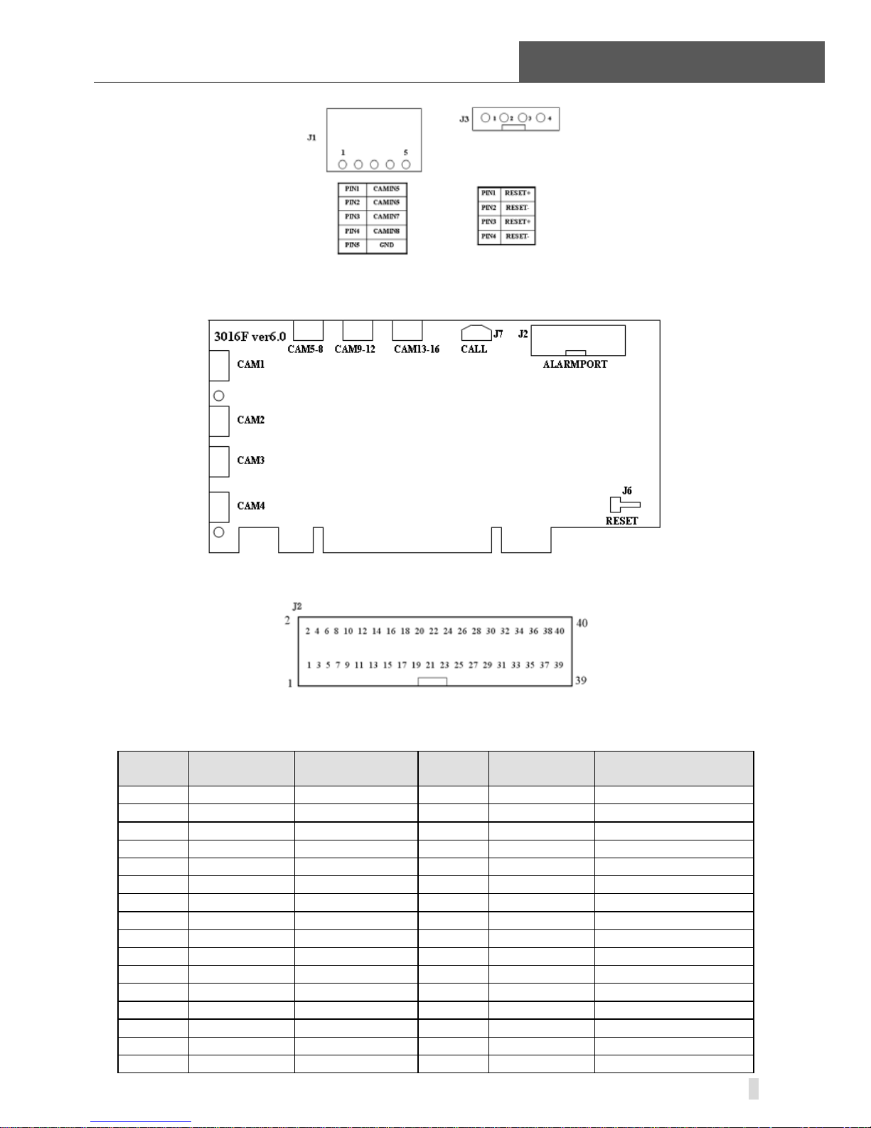
Figure2-5 TD3016 Video Capture Card Circuit Link for Watchdog Function ............................ 9
Figure2-6
TD3016 Video Capture Card Alarm Port ................................................................. 9
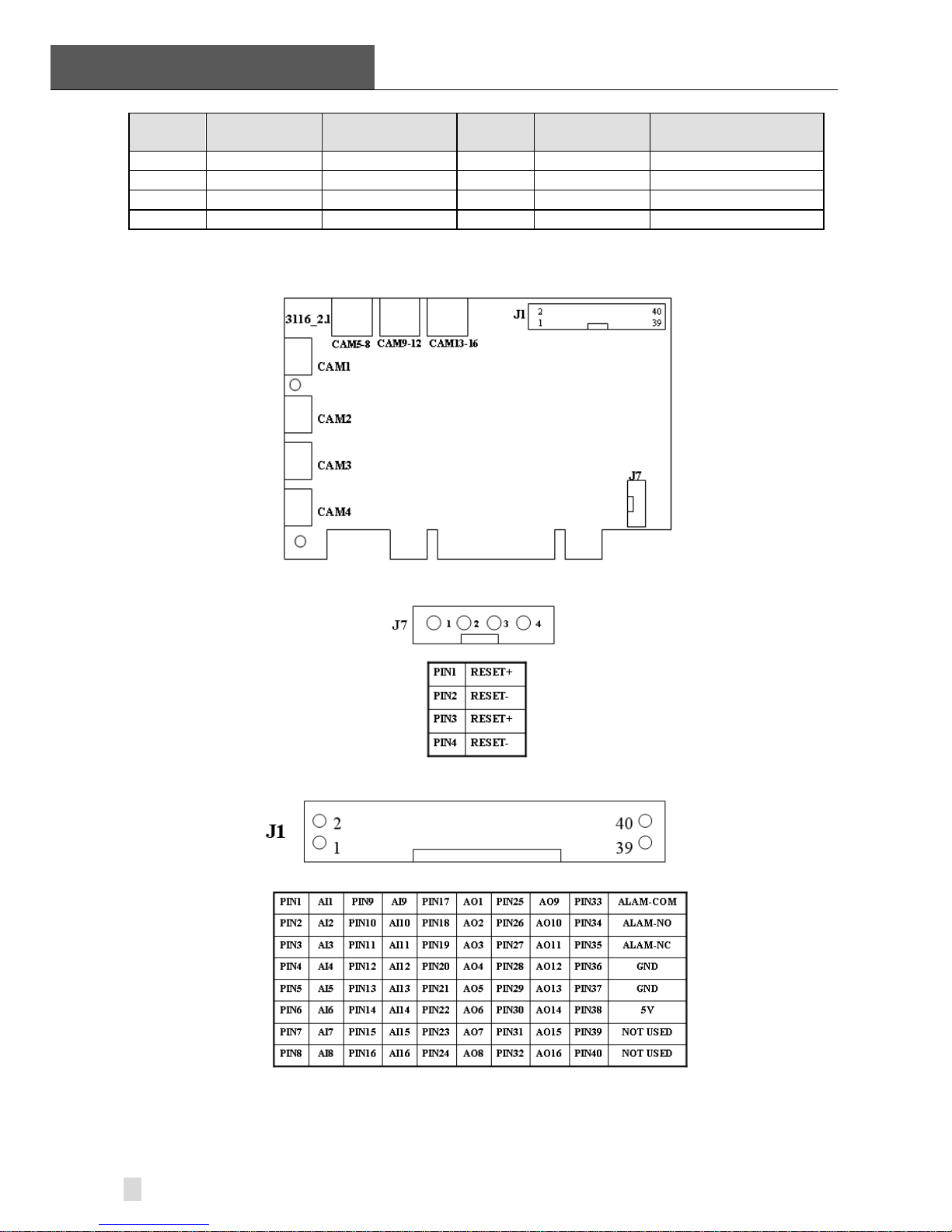
Figure2-7 TD3116 Video Capture Card ................................................................................. 10
Figure2-8
Reset Pins Definitions of TD3116 Video Capture Card .......................................... 10
Figure2-9 Pins Definitions of TD3116 Video Capture Card .................................................... 10
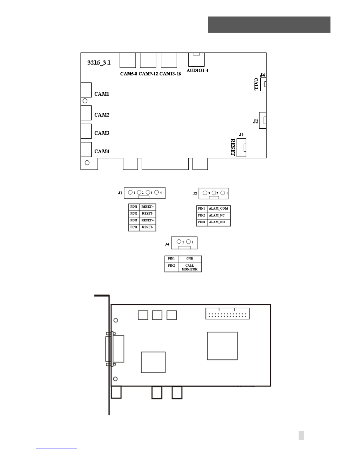
Figure2-10
TD3216 Video Capture Card ................................................................................. 11
Figure2-11
Pins Definitions of TD3216 Video Capture Card .................................................... 11
Figure2-12
TD3308 Video Capture Card ................................................................................. 11
Figure2-13
Video Connector and Pins Definition ..................................................................... 12
Figure2-14
TD3308 Video Capture Card Alarm Port ............................................................... 12
Figure2-15
TD3316 Video Capture Card ................................................................................. 13
Figure2-16
Audio Connector and Pins Definition ..................................................................... 13
Figure2-17
Video Pins Definition ............................................................................................. 14
Figure2-18
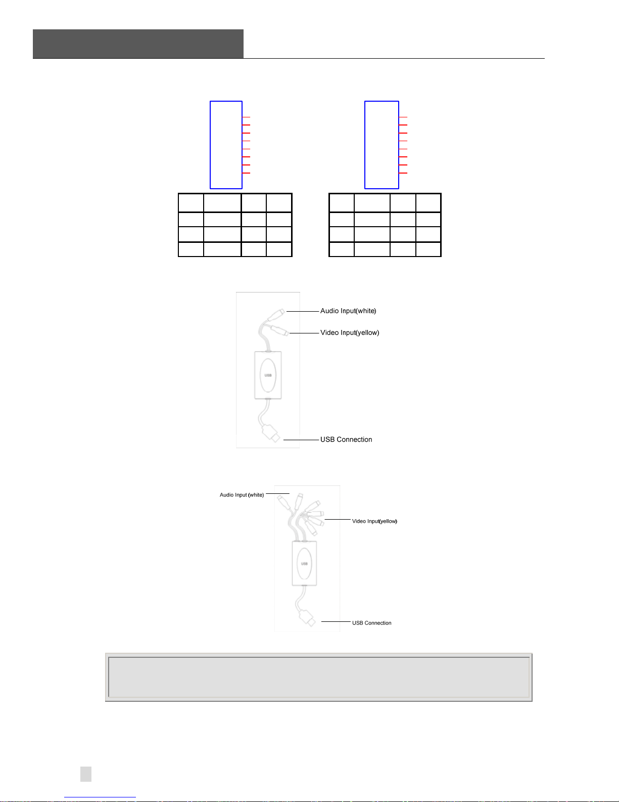
TD3101 USB Video Capture Card ......................................................................... 14
Figure2-19
TD3104 USB Video Capture Card ......................................................................... 14
Figure2-20 TD4104/4404L/4404 Video Capture Card ............................................................. 15
Figure2-21
Definition of Audio and Video Connector’s Pins .................................................... 15
Figure2-22 Multi-Card Connection ........................................................................................... 16
Figure2-23
TD4116 Video Capture Card ................................................................................. 16
Figure2-24
Audio Connector and Pins Definition ..................................................................... 17
Figure2-25
Video Pins Definition ............................................................................................. 17
Figure2-26
TD4316/4416L Video Capture Card ...................................................................... 17
Figure2-27
Definition of Audio Connector and Pins ................................................................. 18
Figure2-28
TD4108/4308/4408/4408L Video Capture Card .................................................... 18
Figure2-29
Definition of Audio and Video Connector’s Pins .................................................... 19
Figure2-30
Multi-Card Connection ........................................................................................... 19
Figure2-31
Alarm Board .......................................................................................................... 20
Figure2-32
Pins Definition of Alarm Board ............................................................................... 20
Figure2-33
TD Series Video Capture Card Installation Interface ............................................. 21
Figure2-34
Welcome Page ...................................................................................................... 21
Figure2-35 Select Video Format .............................................................................................. 21
Figure2-36
Rate of Progress of Driver Installation ................................................................... 22
Figure2-37 Select Installation Folder ....................................................................................... 22
Figure2-38
Register Application ............................................................................................... 22
Figure2-39
Driver and Application Installation Finished ........................................................... 23
Figure2-40
Shortcut of SuperDVR ........................................................................................... 23
Figure2-41
Install the Software on VISTA ................................................................................ 23
Figure3-1
SuperDVR Main Display Interface ......................................................................... 24
Figure3-2
Display Control Panel ............................................................................................ 24
Figure3-3
Display Modes Panel ............................................................................................. 24
Figure3-4
Main Interface ........................................................................................................ 25
Figure3-5
Record Configuration Panel .................................................................................. 26
Figure3-6
Record Status Panel & Alarm Output Status Panel ................................................ 27
Figure4-1
Basic Configuration ............................................................................................... 29
Figure4-2
Caption and General Configuration ....................................................................... 30
Figure4-3
Record Data Storage Precept ................................................................................ 30
Figure4-4
Computer System Reboot Setup ........................................................................... 31

SuperDVR & TD Series Cards
User Manual FIGURES
v
Figure4-5
Video Configuration ............................................................................................... 31
Figure4-6
Motion Detection Configuration ............................................................................. 32
Figure4-7
Schedule Configuration ......................................................................................... 33
Figure4-8
Edit Schedule ........................................................................................................ 34
Figure4-9
Local Alarm Triggering Configuration..................................................................... 34
Figure4-10
Alarm Trigger Method Configuration ...................................................................... 35
Figure4-11
Alarm Output Configuration ................................................................................... 35
Figure4-12
Auto Mail Setup Interface ...................................................................................... 36
Figure4-13
Auto Mail Setup ..................................................................................................... 37
Figure4-14
Attachment Setup .................................................................................................. 37
Figure4-15
E-Map Edit ............................................................................................................. 38
Figure4-16
View Camera ......................................................................................................... 38
Figure4-17 PTZ Configuration Panel ....................................................................................... 39
Figure4-18
P.T.Z Protocol Setup .............................................................................................. 40
Figure4-19 P.T.Z Serial Port Setup .......................................................................................... 40
Figure4-20
User configuration ................................................................................................. 41
Figure4-21
User Password and Rights Edit ............................................................................. 41
Figure4-22
Add User ............................................................................................................... 42
Figure4-23
Confirm Delete User .............................................................................................. 42
Figure5-1
P.T.Z Control Interface ........................................................................................... 43
Figure5-2
P.T.Z Control Function Buttons Panel .................................................................... 43
Figure5-3
Speed Adjustment ................................................................................................. 44
Figure5-4
Preset and Group Select ....................................................................................... 44
Figure5-5
Preset .................................................................................................................... 45
Figure5-6
Group Configuration .............................................................................................. 45
Figure6-1
Search and Playback Interface .............................................................................. 46
Figure6-2
Record Search Area .............................................................................................. 47
Figure6-3 Playing Back and Control ...................................................................................... 47
Figure6-4
Play Speed Controller ............................................................................................ 48
Figure6-5 Record Files Browser ............................................................................................ 48
Figure6-6
Multiple Channels Playing Back Control ................................................................ 49
Figure6-7
Channel Configuration Dialog for Single Channel Playing Back Mode .................. 49
Figure6-8
Channel Configuration Dialog for 4-channel Playing Back Mode .......................... 49
Figure6-9
Channel Configuration Dialog for 9-channel Playing Back Mode .......................... 50
Figure6-10
Channel Configuration Dialog for 16-channel Playing Back Mode ........................ 50
Figure6-11
Recorded Files Backup ......................................................................................... 50
Figure6-12
Delete Recorded Files ........................................................................................... 51
Figure6-13
Color Control Panel ............................................................................................... 52
Figure6-14
Capture Multiple Images in Sequence ................................................................... 52
Figure6-15
Print Setup ............................................................................................................. 52
Figure6-16
Print Preview ......................................................................................................... 53
Figure6-17
Example: original size ............................................................................................ 53
Figure6-18 Example: zoomed out ............................................................................................ 54
Figure6-19
Example: zoomed in .............................................................................................. 54
Fig 7.1 WebCam Server Configuration ........................................................................................... 55
Fig 7.2 WebCam install interface .................................................................................................... 56
Fig 7.3 WebCam Login interface .................................................................................................... 56
Fig 7.4 WebCam Main interface ..................................................................................................... 57
Fig 7.5 Remote play back ............................................................................................................... 59
Fig 7.6 Remote backup .................................................................................................................. 59
Fig 7.7 Channel configuration window for 1 channel play back mode ............................................ 60
Fig7.8 Channel configuration window for 4 channel playback mode .............................................. 60
Fig 7.9 Data Preview ...................................................................................................................... 61
Fig 7.10 Basic Configuration .......................................................................................................... 62
Fig 7.11 Basic setup ....................................................................................................................... 62
Fig 7.12 Computer System Reboot Setup ...................................................................................... 63
Fig 7.13 Alarm triggering configuration ........................................................................................... 63

TABLES
SuperDVR & TD Series Cards
User Manual
vi
Fig 7.14 Camera setup configuration.............................................................................................. 64
Fig 7.15 Schedule configuration ..................................................................................................... 65
Fig 7.16 Alarm configuration ........................................................................................................... 65
Fig 7.17 Record configuration ........................................................................................................ 66
Fig 7.18 Record setup .................................................................................................................... 66
Fig 7.21 Email configuration ........................................................................................................... 68
Fig 7.22 Mail server setup .............................................................................................................. 68
Fig 7.23 Mail setup ......................................................................................................................... 69
Fig 7.24 Attachment setup .............................................................................................................. 69
Fig 7.25 P.T.Z Configuration ........................................................................................................... 70
Fig 7.26 P.T.Z Protocol setup .......................................................................................................... 70
Fig 7.27 P.T.Z Serial port setup ....................................................................................................... 71
Fig 7.28 Open Web Brower ............................................................................................................ 72
Fig 7.29 Build a bookmark .............................................................................................................. 72
Fig 7.30 Connect to Server ............................................................................................................. 73
Fig 7.31 Confirmation Information Window ..................................................................................... 73
Fig 7.32 Installing Configuration Information .................................................................................. 73
Fig 7.33 Scam Shortcut icon in System Menu ................................................................................ 73
Fig 7.34 Main Layout of Scam ........................................................................................................ 74
Fig 7.35 Configuration Login Information ........................................................................................ 74
Fig 7.36 Log in Successfully ........................................................................................................... 74
Fig 7.37 Alarm Setting .................................................................................................................... 75
TABLES
Table1-1 TD3004~TD3216 Series Cards System Requirements ..................................................... 3
Table1-2 TD3304/3308/316 System Requirements .......................................................................... 3
Table1-3 TD3101/3104 System Requirements ................................................................................. 4
Table1-4 TD4104/4404L/4404 System Requirements ...................................................................... 4
Table1-5 TD4116 /4316/4416L/4416System Requirements ............................................................. 5
Table1-6 Motherboards and VGA Cards Support XP OS ................................................................. 5
Table1-7 Motherboards and VGA Cards Support VISTA OS ............................................................ 6
Table1-8 TD4108/ 4308/4408/4408L System Requirements ............................................................ 6
Table2-1 TD3004 Card Pins ............................................................................................................. 7
Table2-2 TD3304 Card Pins ............................................................................................................. 8
Table2-3 Pins Definitions of TD3016 Card ...................................................................................... 10
Table2-4 Pins Definitions of TD3308 Card ...................................................................................... 12
Table 7-1 Mobile Phone of Supporting Mobile Surveillance ............................................................ 72

TD3304, TD3308, TD3316,
TD3016, TD3101, TD3104, TD3116, TD3216,
This manual is suitable for SuperDVR, which supports TD3004 (Defender
82-13110), TD3008,
,
TD4404L
TD4404TD4316
TD4404L
TD4104, TD4116, TD4108, TD4308
SuperDVR & TD Series Cards
User Manual 1 Introduction
1
1
Introduction
1.1 Summarization
Thank you for choosing our digital video capture cards.
1Channel, 4 Channel, 9 Channel, 16 Channel and 32 Channel cards adopt
H.264 compression format, and enable maximum 32 channels real-time or
none real-time surveillance. Our cards are mature and cost-effective products
that should be your ideal choices. They enable synchronous audio and video
compression and transmission, with their powerful compression rate and
network transmission function. They are widely used in banks, intelligent
communities, traffic management units, medical systems, educational
systems, armed forces and so on.
,
,
,
TD4408
,
TD4408L and TD4416L cards.
In this manual, you will learn how to install the hardware and driver (software),
and how to setup the systems of this range of products. Please make sure
your operations with the products are strictly in accordance with the manual,
so as to keep the stability of the digital surveillance systems.
The following are standard functions of the products:
• Schedule record mode
Users can choose any term in a day to record and set up record modes,
i.e. sensor alarm record, motion detection record, manual record,
Schedule Record.
• Motion detection mode
Motion detection areas are adjustable and maximum 16 areas for each
channel. Users can also set motion detection sensitivity for each channel.
The system begins to record only when motion of the detected object
happens, and it will stop recording after a certain period, this function is
adjustable by users.
• Sensor alarm record mode
With extra alarm board, the system enables alarm input and output.
,

1 Introduction
SuperDVR & TD Series Cards
User Manual
2
• Recycling record mode
Users can set recording storage sequence for HDD partitions. The
recording storage will automatically swap to the next partition when it is
full. If all the partitions are full and recycling record mode is enabled, the
former recorded data will be covered by new data. Users can also set
HDD minimum storage alarm. Then once the present storage space is
less then the minimum storage and recycling record mode is not enabled,
the record will automatically stop.
• P.T.Z control function
Support a number of decoders. Users can control multiple speed domes
and integrative cameras, including pan, tilt, zoom, focus and iris
adjustment for P.T.Z devices. Support preset point and auto scout.
• Users management
Different users have different rights, user names and passwords, so as to
ensure system security.
• Multi-channel display
Support different multi-channel display modes, full screen display and
auto dwell display.
• Watch dog function
The 16 Channels card has watchdog function. In case SuperDVR driver or
windows system is frozen, the watchdog will restart the computer and
login SuperDVR system again automatically.
• One PC support 1 to 4 cards of the same model, the maximum frame rate
can be 800 fps and 32 channels at most.
• Support 320x240 / 640x480 (NTSC), 352x288 / 704x576(PAL) standard
resolutions.
• Image color adjustable for each channel, including contrast, lightness, hue
and saturation.
• H.264 compression format, greatly reduce HDD usage
• Powerful video playing back functions, including playing back, pause, stop,
fast-forward, single-frame play and image capture.
• Support advanced search mode. Users can search by date/time, camera,
record mode, and random combination of the three methods.
• Support recorded files backup, delete by date/time, camera.
• Convenient to extend system functions by software upgrade.
• Supply multiple languages, including Chinese (Traditional), English,
German, Spanish, Portuguese and other customized languages.
• CPU and storage resources saving by advanced technology
• Remote Surveillance and P.T.Z control through LAN, Intranet, and
Internet.
• Support alarm pre-record.
• Support buzzer, email alarm out.
• Can greatly decrease fragmented files while using NTFS partition.
• User-friendly graphical user interface.

SuperDVR & TD Series Cards
User Manual 1 Introduction
3
1.2 System Requirements
Our TD series video card support running on Windows VISTA OS. And the
computer which connected the TD series video card required that
motherboard and VGA card could support Windows VISTA OS.
1.2.1 TD3004~ TD3216 Series Cards System Requirements
Card
PC Module
TD3004, TD3008, TD3016, TD3116, TD3216
CPU Intel PIII processor, minimum 800MHz
Motherboard Intel 815/845/865/915 series
HDD 80G minimum
RAM 256M minimum
VGA GeForce2,GeForce4,FX5200,ATI Rage128
OS Windows2000 /XP /VISTA
DirectX 9.0
Table1-1 TD3004~TD3216 Series Cards System Requirements
NOTICE
Notice motherboards listed below which has passed the test can work well with
TD3004~TD3216:
• GIGA: GA-8IRXI (Intel 845D)
• GA-8IE2004 (Intel 845E)
• GA-6OXT (Intel 815EP)
• GA-8PE800 (Intel 845PE)
• GA-8IPE1000-G (Intel 865PE)
• ASUS: P4S8X (Sis 648)
• TUSL2-C (Intel 815EP)
• P4P800 (Intel 865PE)
• MSI: MS-6566E (Intel 845E)
• Intel845DDA+ (Intel 845E)
1.2.2 TD3304/3308/3316 System Requirements
Card
PC Module
TD3304,TD3308, TD3316
CPU Intel P4 2.8G minimum
Motherboard Intel 865/915
HDD 160G minimum
RAM 512M minimum
VGA
NVIDIA GeForce MX440/FX5200
ATI RADEON 7500/ X300/ X250/ X5518
OS Windows 2000(SP4 above) /Windows XP(SP2 above) /VISTA
DirectX 9.0
Table1-2 TD3304/3308/3316 System Requirements
1 Introduction
SuperDVR & TD Series Cards
User Manual
4
NOTICE
1.The computer which installed TD3316 video card requires that motherboard and
VGA card could support Window VISTA OS.
2.Motherboards listed below which has passed the test can work well with TD3316:
• Foxconn 865A01(Intel 865)
• Ga-81pe1000-G 865(Intel 865)
• Asus P4p800 865(Intel 865)
• ASUS P5GD1-VM 915(Intel 915)
• MSI 6728 865(Intel 865)
• Abit IS7-E 865(Intel 865)
• ASUS-P4GPL-X 915(Intel 915)
• ASROCK 775I915PL-SATA2 915(Intel 915)
1.2.3 TD3101/3104 USB Cards System Requirements
Card
PC Module
TD3101, TD3104
CPU Intel P4 Celeron processor,minimum 1700MHz
Motherboard Intel 845/865/915 series
HDD 80G minimum
RAM 256M minimum
VGA
GeForce2,GeForce4,FX5200,ATI Rage128
OS
Windows 2000(SP4 above) /2003(SP2 above) /XP(SP2 above)
/VISTA
DirectX 9.0
USB 2.0
Table1-3 TD3101/3104 System Requirements
1.2.4 TD4104 /440 4L/4404 Card System Requirements
Card
PC Module
TD4104, TD 4404L, TD 4404
CPU Intel P4 Celeron processor 2.0G minimum
HDD 80G minimum
RAM 256M minimum
OS Windows 2000 /2003 /XP /VISTA
DirectX 9.0
Table1-4 TD4104/4404L/4404 System Requirements
NOTICE
1. Motherboards listed below which have passed the test can work well with TD4104:
• Intel 865G
• GA-945PL-S3E
• GA965P-S3
• GA-K8V7890-9
• GA-8IE2004P
• ASUS P5PL2
• ASUS P5B-E
2. VGA cards listed below which have passed the test can work well with TD4104:
• ATI X1600
• ATI X300
• NVIDIA Geforce 7300LE

SuperDVR & TD Series Cards
User Manual 1 Introduction
5
• NVIDIA Geforce 7600GS
• NVIDIA Geforce 8500GT
If recorded disk partition’s format is FAT32 and the system has run for a long
time, the system will create a lot of data fragments that may results in system
runs slowly. It’s recommended to make disk defragmenter every 10 to 30 days.
We strongly suggest that use NTFS format for record disk partition.
1.2.5 TD4116/4316/4416L/4416 Card System Requirements
Card
PC Module
TD4116,TD 4316,TD 4416L,TD 4416
CPU Intel P4 Celeron processor 2.0G minimum
HDD 80G minimum
RAM 256M minimum
OS Windows 2000/2003/XP/VISTA
DirectX 9.0
Table1-5 TD4116 /4316/4416L/4416System Requirements
Motherboards and VGA cards listed below which have passed the test can
work well with TD4116 in Windows XP system:
Motherboard
V
GA card
COLORFUL C975X-MVP
ATI HD2400
NVIDIA GeForce 7600
NVIDIA GeForce 7300
ASUS P5LD2-X
ATI HD2400
ATI X300
ASUS P5B
ATI HD2400
NVIDIA GeForce 7600
NVIDIA GeForce 7300
ATI X300
GA-965P-S3
ATI HD2400
NVIDIA GeForce 7300
ATI X300
GA-945PL-S3E
ATI HD2400
NVIDIA GeForce 7600
ATI X300
ASUS P5L-1394
ATI HD2400
NVIDIA GeForce 7600
ATI X300
ASUS P5GD1-VM
ATI HD2400
NVIDIA GeForce 7600
ATI X300
ATI X700
Table1-6 Motherboards and VGA Cards Support XP OS
Motherboards and VGA cards listed below which have passed the test can
work well with TD4116 in Windows VISTA system:
Motherboard
V
GA card
COLORFUL C975X-MVP ATI HD2400
ASUS P5LD2-X
ATI HD2400
ATI X300
GA-965P-S3 ATI HD2400
1 Introduction
SuperDVR & TD Series Cards
User Manual
6
Motherboard
V
GA card
ATI X300
ASUS P5L-1394
ATI HD2400
ATI X300
ASUS P5GD1-VM
ATI HD2400
ATI X300
ATI X700
Table1-7 Motherboards and VGA Cards Support VISTA OS
1.2.6 TD4108/ 4308/4408/4408L Cards System Requirements
Card
PC Module
TD4108,TD4308,
TD4408,TD4408L *one card
TD4108,TD4308,
TD4408,TD4408L *four cards
CPU
Intel P4 Celeron processor
3.0G minimum
Intel PD Dual-core 2.8 G above
HDD 80G minimum 160G minimum
RAM 512M minimum 2.0G minimum
OS Windows 2000/2003/XP/VISTA
DirectX 9.0
Table1-8 TD4108/ 4308/4408/4408L System Requirements
1.3 System Specifications
• Format: PAL/NTSC.
• Resolution: TD3004, 3008, 3016, 3116, 3216, 3101, 3104 support
320x240 / 640x480 (NTSC), 352x288 / 704x576(PAL),TD3304,3308 support
320x240(NTSC), 352x288(PAL),TD3316 supports 352 × 240 / 704 ×
480(NTSC), 352x288 / 704x576(PAL) ,TD4104 supports 320×240(NTSC) ,
352×288(PAL) ,TD4108 supports 320×240(NTSC) , 352×288(PAL) and TD
4308,4316,4404,4404L,4408,4408L,4416L supports 704x576(PAL).
• Maximum Frame rate per channel: 25 fps (PAL), 30 ftp (NTSC).
• Screen set: resolution 1024×768, color quality 16 bits or 32 bits.
• Compression code rate: 50kbps – 1.2Mbps.
• Data format: H.264
SuperDVR & TD Series Cards
User Manual 2 Hardware Installation
7
2 Hardware Installation
2.1 Video Capture Card Hardware
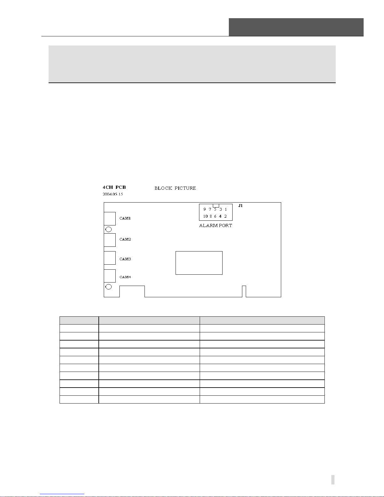
2.1.1 TD3004 Card Hardware
Figure2-1 TD3004 Video Capture Card
Pin Port Define Interpret
1PIN 5V Power Source (5V)
2PIN ALARM_COM Alarm COM
3PIN ALARM_NC Alarm Normal Close
4PIN ALARM_IN1 Alarm Input 1
5PIN ALARM_NO Alarm Normal Open
6PIN ALARM_IN2 Alarm Input 2
7PIN GND Ground
8PIN ALARM_IN3 Alarm Input 3
9PIN GND Ground
10PIN ALARM_IN4 Alarm Input 4
Table2-1 TD3004 Card Pins

2 Hardware Installation
SuperDVR & TD Series Cards
User Manual
8
2.1.2 TD3304 Card Hardware
Figure2-2 TD3304 Video Capture Card
Pin Port Define Interpret
1PIN 5V Power Source (5V)
2PIN ALARM_COM Alarm COM
3PIN ALARM_NC Alarm Normal Close
4PIN ALARM_IN1 Alarm Input 1
5PIN ALARM_NO Alarm Normal Open
6PIN ALARM_IN2 Alarm Input 2
7PIN GND Ground
8PIN ALARM_IN3 Alarm Input 3
9PIN GND Ground
10PIN ALARM_IN4 Alarm Input 4
Table2-2 TD3304 Card Pins
2.1.3 TD3008 Card Hardware
Figure2-3 TD3008 Video Capture Card
SuperDVR & TD Series Cards
User Manual 2 Hardware Installation
9
Figure2-4 Pins Definitions of TD3008 Video Capture Card
2.1.4 TD3016 Card Hardware
Figure2-5 TD3016 Video Capture Card Circuit Link for Watchdog Function
Figure2-6 TD3016 Video Capture Card Alarm Port
The Alarm Port pin definitions of TD3016 Card are as below:
Pin
Port
Define Interpret
Pin
Port
Define Interpret
Pin1 Alarm_in1 Alarm Input 1 Pin21 Alarm_out5 Alarm Output 5
Pin2 Alarm_in2 Alarm Input 2 Pin22 Alarm_out6 Alarm Output 6
Pin3 Alarm_in3 Alarm Input 3 Pin23 Alarm_out7 Alarm Output 7
Pin4 Alarm_in4 Alarm Input 4 Pin24 Alarm_out8 Alarm Output 8
Pin5 Alarm_in5 Alarm Input 5 Pin25 Alarm_out9 Alarm Output 9
Pin6 Alarm_in6 Alarm Input 6 Pin26 Alarm_out10 Alarm Output 10
Pin7 Alarm_in7 Alarm Input 7 Pin27 Alarm_out11 Alarm Output 11
Pin8 Alarm_in8 Alarm Input 8 Pin28 Alarm_out12 Alarm Output 12
Pin9 Alarm_in9 Alarm Input 9 Pin29 Alarm_out13 Alarm Output 13
Pin10 Alarm_in10 Alarm Input 10 Pin30 Alarm_out14 Alarm Output 14
Pin11 Alarm_in11 Alarm Input 11 Pin31 Alarm_out15 Alarm Output 15
Pin12 Alarm_in12 Alarm Input 12 Pin32 Alarm_out16 Alarm Output 16
Pin13 Alarm_in13 Alarm Input 13 Pin33 Alarm_Com Alarm COM
Pin14 Alarm_in14 Alarm Input 14 Pin34 Alarm_NO Alarm Normal Open
Pin15 Alarm_in15 Alarm Input 15 Pin35 Alarm_NC Alarm Normal Close
Pin16 Alarm_in16 Alarm Input 16 Pin36 GND Ground
2 Hardware Installation
SuperDVR & TD Series Cards
User Manual
10
Pin
Port
Define Interpret
Pin
Port
Define Interpret
Pin17 Alarm_out1 Alarm Output 1 Pin37 GND Ground
Pin18 Alarm_out2 Alarm Output 2 Pin38 5V Power Source (5V)
Pin19 Alarm_out3 Alarm Output 3 Pin39 Not Used Not Used
Pin20 Alarm_out4 Alarm Output 4 Pin40 Not Used Not Used
Table2-3 Pins Definitions of TD3016 Card
2.1.5 TD3116 Card Hardware
Figure2-7 TD3116 Video Capture Card
Figure2-8 Reset Pins Definitions of TD3116 Video Capture Card
Figure2-9 Pins Definitions of TD3116 Video Capture Card
SuperDVR & TD Series Cards
User Manual 2 Hardware Installation
11
2.1.6 TD3216 Card Hardware
Figure2-10 TD3216 Video Capture Card
Figure2-11 Pins Definitions of TD3216 Video Capture Card
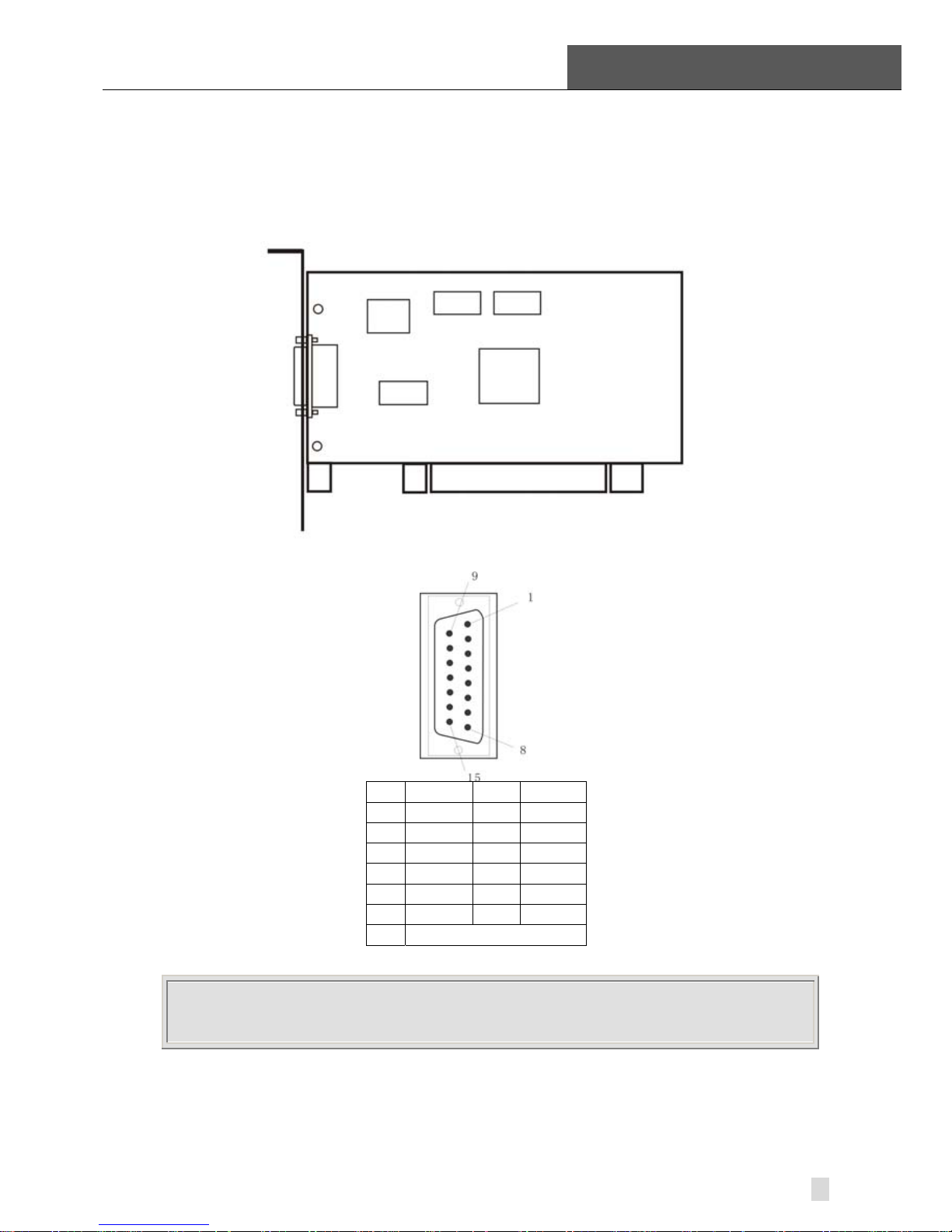
2.1.7 TD3308 Card Hardware
Figure2-12 TD3308 Video Capture Card

2 Hardware Installation
SuperDVR & TD Series Cards
User Manual
12
VINc h2
VINc h3
VINc h4
VINc h5
VINc h6
VINc h7
VINc h8
AGND
P1
CONNECTOR DB15
8
15
7
14
6
13
5
12
4
11
3
10
2
9
1
16
17
VINc h1
AGND
PIN1 Video1 PIN6 Video6
PIN2 Video2 PIN7 Video7
PIN3 Video3 PIN8 Video8
PIN4 Video4 Pin9-pin15 GND
PIN5 Video5
Figure2-13 Video Connector a nd Pins Definition
Figure2-14 TD3308 Video Captur e Card Alarm Port
Pin
Port
Define Interpret
Pin
Port
Define Interpret
Pin1 Alarm_in1 Alarm Input 1 Pin21
Pin2 Alarm_in2 Alarm Input 2 Pin22
Pin3 Alarm_in3 Alarm Input 3 Pin23
Pin4 Alarm_in4 Alarm Input 4 Pin24
Pin5 Alarm_in5 Alarm Input 5 Pin25
Pin6 Alarm_in6 Alarm Input 6 Pin26
Pin7 Alarm_in7 Alarm Input 7 Pin27
Pin8 Alarm_in8 Alarm Input 8 Pin28
Pin9 Pin29
Pin10 Pin30
Pin11 Pin31
Pin12 Pin32
Pin13 Pin33
Pin14 Pin34 Alarm_Com Alarm COM
Pin15 Pin35 Alarm_NO Alarm Normal Open
Pin16 Pin36 GND Ground
Pin17 Pin37 GND Ground
Pin18 Pin38 5V Power Source (5V)
Pin19 Pin39 Alarm_NC Alarm Normal Close
Pin20 Pin40
Table2-4 Pins Definitions of TD3308 Card

SuperDVR & TD Series Cards
User Manual 2 Hardware Installation
13
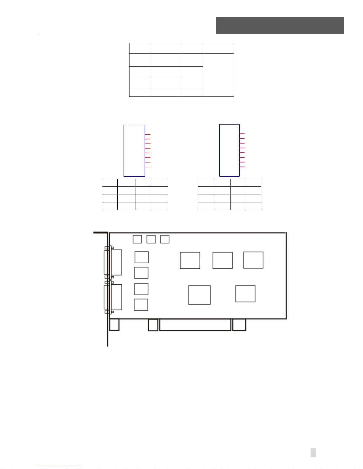
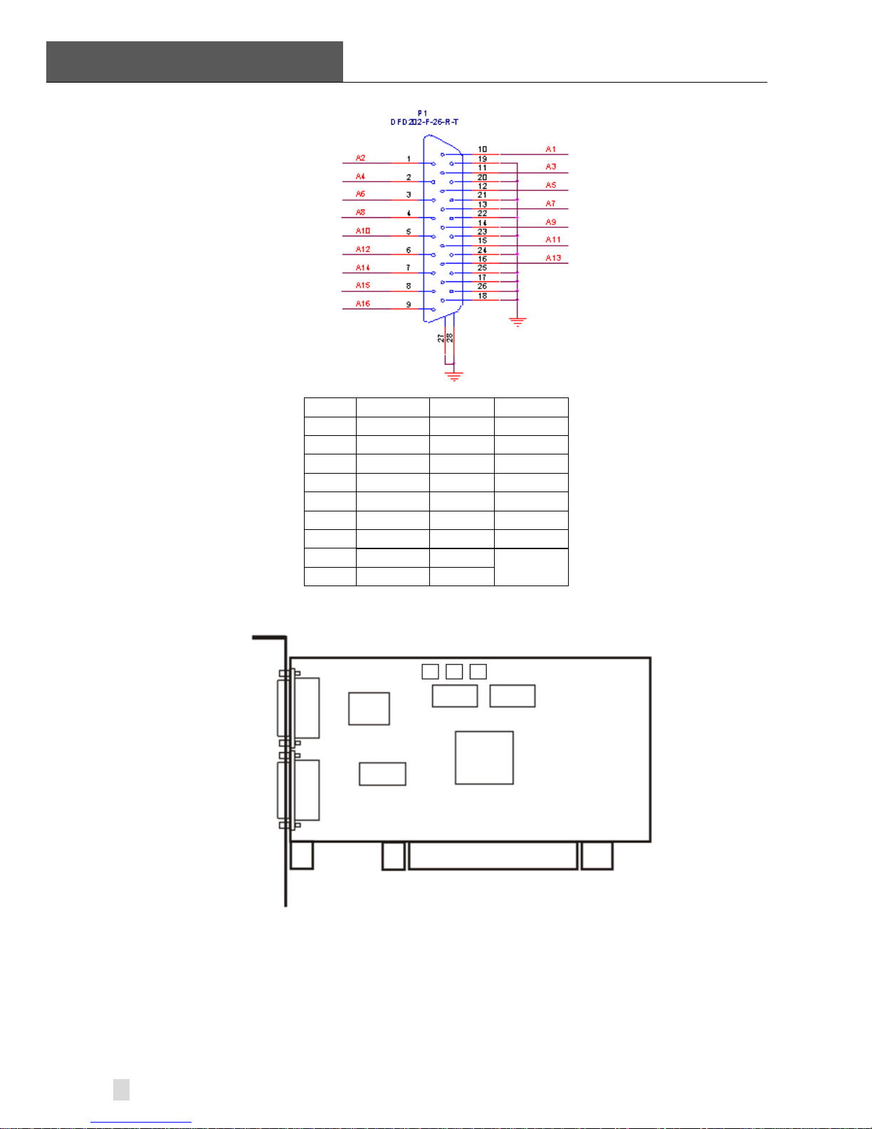
2.1.8 TD3316 Card Hardware
Figure2-15 TD3316 Video Capture Card
P2
DFD202-F-26-R-T
1
2
3
4
5
6
7
8
9
10
11
12
13
14
15
16
17
18
19
20
21
22
23
24
25
26
28
27
PIN1 AUDIO2 PIN11 AUDIO3
PIN2 AUDIO4 PIN12 AUDIO5
PIN3 AUDIO6 PIN13 AUDIO7
PIN4 AUDIO8 PIN14 AUDIO9
PIN5 AUDIO10 PIN15 AUDIO11
PIN6 AUDIO12 PIN16 AUDIO13
PIN7 AUDIO14 PIN17
GND
PIN8 AUDIO15
/ PIN9 AUDIO16
PIN10 AUDIO1 PIN26
Figure2-16 Audio Connector and Pins Definition
J1
GiL-G-8P-S3T2-E
1
2
3
4
5
6
7
8
J2
GiL-G-8P-S3T2-E
1
2
3
4
5
6
7
8
PIN1 VIN-1 PIN2 GND PIN1 VIN-5PIN2 GND
PIN3 VIN-2 PIN4 GND PIN3 VIN-6PIN4 GND
PIN5 VIN-3 PIN6 GND PIN5 VIN-7PIN6 GND
PIN7 VIN-4 PIN8 GND PIN7 VIN-8PIN8 GND
2 Hardware Installation
SuperDVR & TD Series Cards
User Manual
14
J3
GiL-G-8P-S3T2-E
1
2
3
4
5
6
7
8
J4
GiL-G-8P-S3T2-E
1
2
3
4
5
6
7
8
PIN1 VIN-9 PIN2 GND PIN1 VIN-13 PIN2 GND
PIN3 VIN-10 PIN4 GND PIN3 VIN-14 PIN4 GND
PIN5 VIN-11 PIN6 GND PIN5 VIN-15 PIN6 GND
PIN7 VIN-12 PIN8 GND PIN7 VIN-16 PIN8 GND
Figure2-17 Video Pins Definition
2.1.9 TD3101 USB Card Hardware
Figure2-18 TD3101 USB Video Capture Card
2.1.10 TD3104 USB Card Hardware
Figure2-19 TD3104 USB Video Capture Card
NOTICE
• Make sure that your PC USB interface is 2.0.
• TD3101/3104 card can only support USB 2.0.
Please accord to the following steps to safely remove the USB card: Right
clicks on the Taskbar Stop device pull out the USB card.
Using TD3101/3104 card with other USB device simultaneously may cause
SuperDVR & TD Series Cards
User Manual 2 Hardware Installation
15
PC cannot identify USB card.
Do not insert two or more USB video capture cards simultaneously.
Do not use with the other PCI video capture card simultaneously.
2.1.11 TD4104/44 04L/4404 Card Hardware
Figure2-20 TD4104/4404L/4404 Video Capture Card
PIN1 VIDEO-1 PIN9 GND
PIN2 GND PIN10AUDIO-1
PIN3 VIDEO-2 PIN11AUDIO-2
PIN4 GND PIN12AUDIO-3
PIN5 VIDEO-3 PIN13AUDIO-4
PIN6 GND PIN14 NULL
PIN7 VIDEO-4 PIN15 GND
PIN8 GND
Figure2-21 Definition of Audio and Video Connector’s Pins
NOTICE
Our TD4104 cards have two different ports; please refer to your user manual according
to the product you purchase.
When there are some TD4104 card connects together, please connect the
line as following figure.

2 Hardware Installation
SuperDVR & TD Series Cards
User Manual
16
Figure2-22 Multi-Card Connection
2.1.12 TD4116 Card Hardware
Figure2-23 TD4116 Video Capture Card
P2
DFD202-F-26-R-T
1
2
3
4
5
6
7
8
9
10
11
12
13
14
15
16
17
18
19
20
21
22
23
24
25
26
28
27
PIN1 AUDIO2 PIN11 AUDIO3
PIN2 AUDIO4 PIN12 AUDIO5
PIN3 AUDIO6 PIN13 AUDIO7
PIN4 AUDIO8 PIN14 AUDIO9
PIN5 AUDIO10 PIN15 AUDIO11
SuperDVR & TD Series Cards
User Manual 2 Hardware Installation
17
PIN6 AUDIO12 PIN16 AUDIO13
PIN7 AUDIO14 PIN17
GND
PIN8 AUDIO15
/ PIN9 AUDIO16
PIN10 AUDIO1 PIN26
Figure2-24 Audio Connector and Pins Definition
J1
GiL-G-8P-S3T2-E
1
2
3
4
5
6
7
8
J2
GiL-G-8P-S3T2-E
1
2
3
4
5
6
7
8
PIN1 VIN-1 PIN2 GND PIN1 VIN-5 PIN2 GND
PIN3 VIN-2 PIN4 GND PIN3 VIN-6 PIN4 GND
PIN5 VIN-3 PIN6 GND PIN5 VIN-7 PIN6 GND
PIN7 VIN-4 PIN8 GND PIN7 VIN-8 PIN8 GND
Figure2-25 Video Pins Definition
2.1.13 TD4316/44 16L Card Hardware
Figure2-26 TD4316/4416L Video Capture Card
2 Hardware Installation
SuperDVR & TD Series Cards
User Manual
18
PIN1 AUDIO2 PIN11 AUDIO3
PIN2 AUDIO4 PIN12 AUDIO5
PIN3 AUDIO6 PIN13 AUDIO7
PIN4 AUDIO8 PIN14 AUDIO9
PIN5 AUDIO10 PIN15 AUDIO11
PIN6 AUDIO12 PIN16 AUDIO13
PIN7 AUDIO14 PIN17
PIN8 AUDIO15 PIN18
PIN9 AUDIO16
GND PIN10 AUDIO1 PIN19-26
Figure2-27 Definition of Audio Connector and Pins
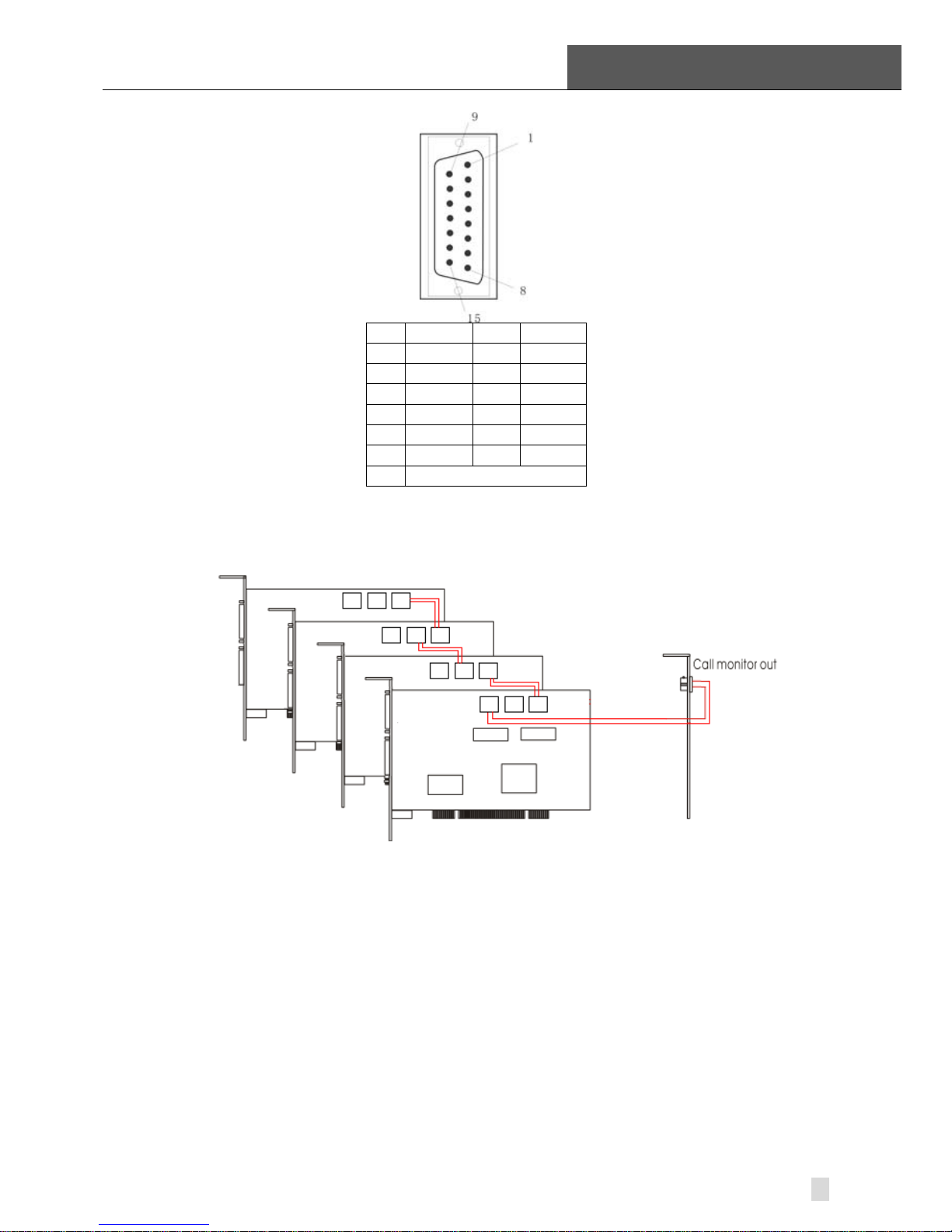
2.1.14 TD4108/43 08/4408/4408L Card Hardware
Figure2-28 TD4108/4308/4408/4408L Video Capture Card
SuperDVR & TD Series Cards
User Manual 2 Hardware Installation
19
PIN1 VIDEO-1 PIN9 GND
PIN2 GND PIN10AUDIO-1
PIN3 VIDEO-2 PIN11AUDIO-2
PIN4 GND PIN12AUDIO-3
PIN5 VIDEO-3 PIN13AUDIO-4
PIN6 GND PIN14 NULL
PIN7 VIDEO-4 PIN15 GND
PIN8 GND
Figure2-29 Definition of Audio and Video Connector’s Pins
When there are some TD4108 cards connect together, please connect the
line as following figure.
Figure2-30 Multi-Card Connection
2 Hardware Installation
SuperDVR & TD Series Cards
User Manual
20
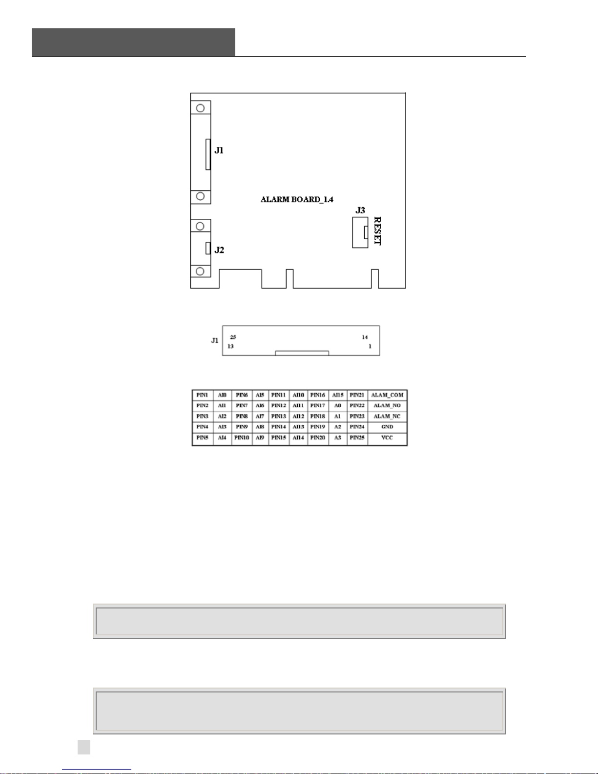
2.1.15 Alarm Board Hardware
Figure2-31 Alarm Board
Figure2-32 Pins Definition of Alarm Board
Connect J2 to PC serial port and you may use alarm board by SuperDVR
system.
2.1.16 Connect Audio Signal
For TD3004/3008/3016/3304/3116/3216/4104/4108/4408, connect the audio
input device to the microphone connector on the motherboard.
Before installing the Video Capture Card hardware in PCI port of the
motherboard, make sure you’ve installed Microsoft DirectX 9.0. Then turn on
the computer, the system will remind you to ‘Found new hardware’.
NOTICE
Just click ‘Cancel’ and ignore the pop-up message.
Insert the CD that contains TD series capture card driver into the CD tray, and
run Setup.exe program to install the driver. The default installation path is
‘C:\Program Files\SuperDVR’.
NOTICE
In case it warns that ‘Can’t find card’ when running the SuperDVR software, please
restart the computer.
SuperDVR & TD Series Cards
User Manual 2 Hardware Installation
21
2.2 Install Video Capture Card Driver
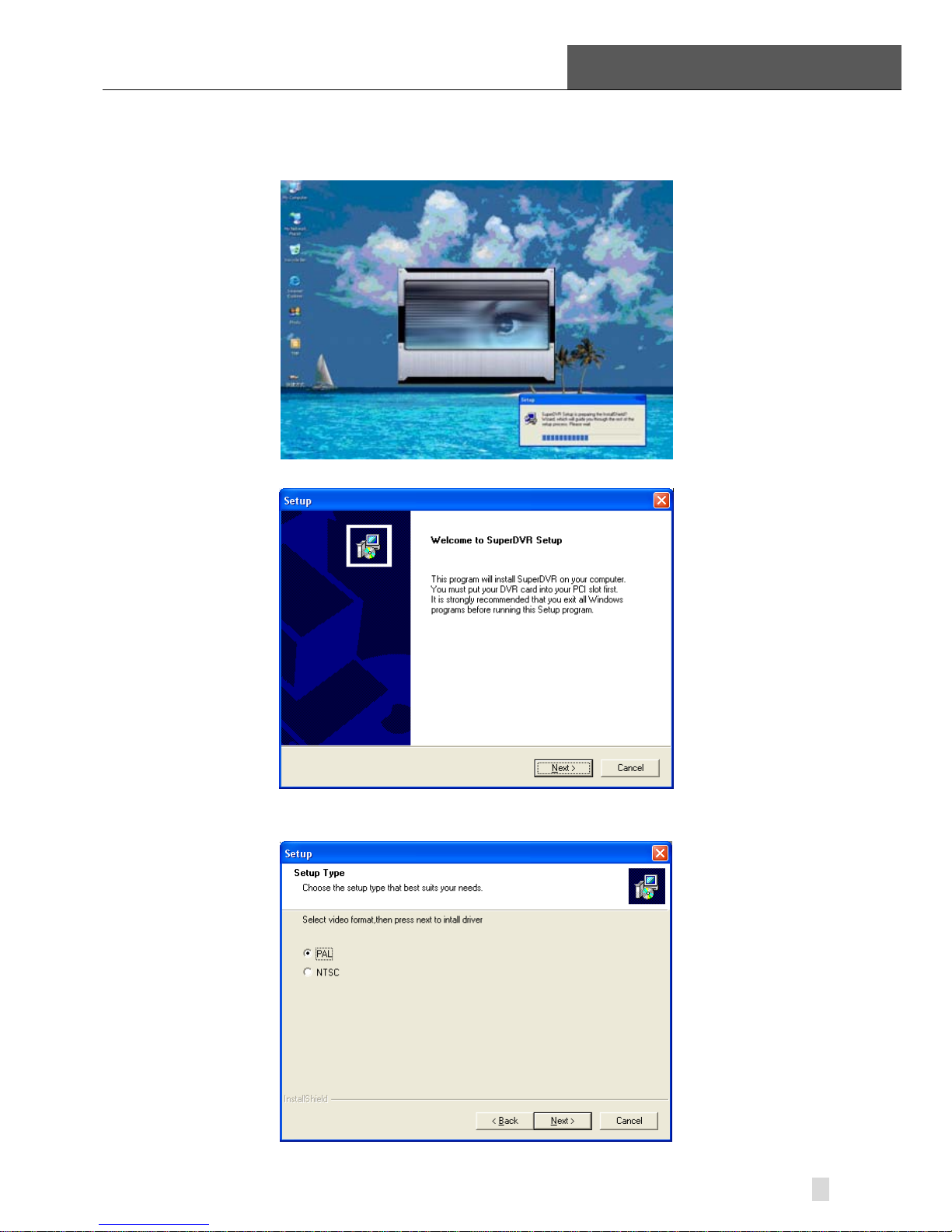
STEP1: Run Setup.exe, and the installation interface appears as below:
Figure2-33 TD Series Video Capture Card Installation Interface
Figure2-34 Welcome Page
STEP2: Select video system, click “next”
Figure2-35 Select Video Format
2 Hardware Installation
SuperDVR & TD Series Cards
User Manual
22
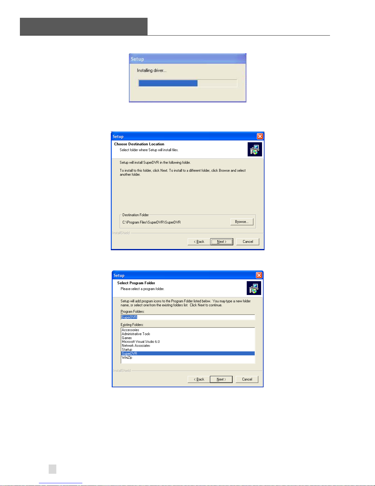
STEP3: Install driver first.
Figure2-36 Rate of Progress of Driver Installation
STEP4: After this process, it begins to install the application package
SuperDVR, as below:
Figure2-37 Select Installation Folder
STEP5: Select the suitable option, and click ‘Next’.
Figure2-38 Register Application
STEP6: Click ‘Next’.
 Loading...