

Page 1

DVR MANUAL
4K1T4B4 – 4K2T8B8 – 4K4T16B16
Page 2

DVR MANUAL
TABLE OF CONTENTS
1
TABLE OF CONTENTS
1 THANK YOU ............................................................................................................................................................................................. 1
1.1 SUPPORT ..................................................................................................................................................................................... 4
1.2 FEEDBACK .................................................................................................................................................................................... 4
2 WARRANTY INFORMATION ................................................................................................................................................................... 5
3 DISCLAIMERS .......................................................................................................................................................................................... 6
4 SAFETY WARNINGS ................................................................................................................................................................................. 7
5 COMPLIANCE STATEMENTS .................................................................................................................................................................. 8
5.1 FCC STATEMENT ......................................................................................................................................................................... 8
5.2 IC STATEMENT ............................................................................................................................................................................. 8
6 WHATS INCLUDED .................................................................................................................................................................................. 9
7 GETTING STARTED ................................................................................................................................................................................ 10
7.1 FUNCTIONS ............................................................................................................................................................................... 10
7.1.1 DVR .............................................................................................................................................................................. 10
7.1.2 Camera ........................................................................................................................................................................ 10
7.2 DVR SETUP ................................................................................................................................................................................. 11
7.3 MOUSE CONTROLS .................................................................................................................................................................. 12
7.4 ON-SCREEN KEYBOARD ........................................................................................................................................................... 13
7.1 STANDARD MENU COMMAND BUTTONS.............................................................................................................................. 13
7.2 ADDITIONAL INFORMATION ................................................................................................................................................... 14
8 SYSTEM SETUP ...................................................................................................................................................................................... 15
8.1 ACTIVATION SCREENS .............................................................................................................................................................. 15
8.2 SETUP WIZARD .......................................................................................................................................................................... 17
9 USING YOUR SYSTEM ........................................................................................................................................................................... 21
9.1 LIVE VIEW ................................................................................................................................................................................... 21
9.2 RIGHT CLICK MENU .................................................................................................................................................................. 22
9.3 LOGIN & PASSWORD RESET .................................................................................................................................................... 26
9.3.1 Login ............................................................................................................................................................................ 26
9.3.2 Password Reset .......................................................................................................................................................... 26
9.4 SHUT DOWN.............................................................................................................................................................................. 27
9.5 RESTORING SYSTEM DEFAULTS .............................................................................................................................................. 28
Page 3

DVR MANUAL
TABLE OF CONTENTS
2
10 PLAYBACK .............................................................................................................................................................................................. 29
11 EXPORT .................................................................................................................................................................................................. 31
11.1 NORMAL .................................................................................................................................................................................... 31
11.2 EVENT ......................................................................................................................................................................................... 33
11.3 EXPORTING ................................................................................................................................................................................ 34
12 VIDEO RECORD SETTINGS ................................................................................................................................................................... 37
12.1 SCHEDULE ................................................................................................................................................................................. 37
12.2 PARAMETERS ............................................................................................................................................................................. 38
12.3 ADVANCED ................................................................................................................................................................................ 40
12.4 HOLIDAY .................................................................................................................................................................................... 40
13 CAMERA SETTINGS ............................................................................................................................................................................... 41
13.1 CAMERA ..................................................................................................................................................................................... 41
13.2 OSD (ON-SCREEN DISPLAY) ..................................................................................................................................................... 41
13.3 IMAGE ........................................................................................................................................................................................ 42
13.3.1 Image Settings ............................................................................................................................................................ 42
13.3.2 Camera Parameter Settings ..................................................................................................................................... 43
13.4 MOTION ..................................................................................................................................................................................... 44
13.5 PRIVACY MASK .......................................................................................................................................................................... 45
13.6 VIDEO TAMPERING ................................................................................................................................................................... 46
13.7 VIDEO LOSS ............................................................................................................................................................................... 47
13.8 VCA ............................................................................................................................................................................................. 48
13.9 VIDEO QUALITY DIAGNOSTICS ................................................................................................................................................ 49
14 CONFIGURATION .................................................................................................................................................................................. 50
14.1 GENERAL .................................................................................................................................................................................... 50
14.1.1 General Settings ......................................................................................................................................................... 50
14.1.2 DST Settings ................................................................................................................................................................ 51
14.1.3 More Settings ............................................................................................................................................................. 52
14.2 NETWORK .................................................................................................................................................................................. 52
14.2.1 Email ............................................................................................................................................................................ 53
14.3 LIVE VIEW ................................................................................................................................................................................... 54
14.3.1 General........................................................................................................................................................................ 54
14.3.2 View ............................................................................................................................................................................. 55
Page 4

DVR MANUAL
TABLE OF CONTENTS
3
14.3.3 Channel-Zero Encoding ............................................................................................................................................. 55
14.4 EXCEPTIONS .............................................................................................................................................................................. 56
14.5 USER SETUP ............................................................................................................................................................................... 57
15 MANUAL CAMERA SETTINGS .............................................................................................................................................................. 58
15.1 RECORD ..................................................................................................................................................................................... 58
15.2 MANUAL VIDEO QUALITY DIAGNOSTICS ............................................................................................................................... 59
16 HDD SETTINGS ...................................................................................................................................................................................... 60
16.1 HDD INFORMATION ................................................................................................................................................................. 60
16.2 ADVANCED ................................................................................................................................................................................ 61
17 SYSTEM MAINTENANCE ....................................................................................................................................................................... 62
17.1 SYSTEM INFO ............................................................................................................................................................................. 62
17.2 LOG INFORMATION .................................................................................................................................................................. 62
17.3 IMPORT/EXPORT ....................................................................................................................................................................... 63
17.4 UPGRADE ................................................................................................................................................................................... 63
17.5 NET DETECT ............................................................................................................................................................................... 64
17.6 HDD DETECT ............................................................................................................................................................................. 64
18 ANALYTICS (IP CAMERA REQUIRED) ................................................................................................................................................... 65
18.1 BEHAVIOR SEARCH ................................................................................................................................................................... 65
18.2 FACE SEARCH ............................................................................................................................................................................ 66
18.3 PLATE SEARCH .......................................................................................................................................................................... 66
18.4 PEOPLE COUNTING .................................................................................................................................................................. 67
18.5 HEAT MAP .................................................................................................................................................................................. 67
19 CAMERA INSTALLATION ...................................................................................................................................................................... 69
Page 5

DVR MANUAL
TABLE OF CONTENTS
4
1 THANK YOU
Congratulations on your Defender 4K purchase! You’ve made the best choice to protect what you value
most.
We take our product performance and quality very seriously and we want you to be completely satisfied with
your purchase.
If you have any questions, or to get the most out of your product, visit us at www.defender-usa.com first for
additional product information, specifications or assistance with setup.
1.1 SUPPORT
1.2 FEEDBACK
At DEFENDER® we’re always looking to improve our customer’s experience! Please share any
suggestions for this product manual to help us continue on this journey.
FEEDBACK SURVEY LINK
www.defender-usa.com/support/
www.defender-usa.com/contact/
www.defender-usa.com/videos/
Page 6
DVR MANUAL
TABLE OF CONTENTS
5
2 WARRANTY INFORMATION
All of our products come with a one-year warranty from the original date of purchase against defects in
workmanship and materials. If you have warranty or support issues, please contact us at:
WARRANTY TERMS
1. DEFENDER® products are guaranteed for a period of one year from the date of purchase against defects
in workmanship and materials. This warranty is limited to the repair, replacement or refund of the
purchase price at DEFENDER®’s option.
2. This warranty becomes void if the product shows evidence of having been misused, mishandled or
tampered with contrary to the applicable instruction manual.
3. Routine cleaning, normal cosmetic, and mechanical wear and tear are not covered under the terms of
this warranty.
4. The warranty expressly provided for herein is the sole warranty provided in connection with the product
itself and no other warranty, expressed or implied is provided. DEFENDER® assumes no responsibilities
for any other claims not specifically mentioned in this warranty.
5. The warranty does not cover shipping costs, insurance or any other incidental charges.
6. You MUST contact DEFENDER® before sending any product back for repair. You will be sent a Return
Authorization Number with return instructions. When returning the product for warranty service, please
pack it carefully in the original box with all supplied accessories, and enclose your original receipt or
copy, and a brief explanation of the problem (include the RA#).
7. This warranty is valid in Canada and the contiguous US.
8. This warranty cannot be re-issued.
9. Tearing the tamper-proof sticker on the DVR cases will void the product warranty.
https://www.defender-usa.com/contact/
www.defender-usa.com
DEFENDER® Canada: 4080 Montrose Road Niagara Falls, Ontario, Canada L2H 1J9
DEFENDER® USA: 840 Aero Drive Cheektowaga, New York, USA 14225
Page 7

DVR MANUAL
TABLE OF CONTENTS
6
3 DISCLAIMERS
1. When viewing remotely: Video quality and connectivity is dependent on network performance.
2. DEFENDER® highly recommends the use of an Uninterruptible Power Supply (UPS) with surge protection
for all products.
3. The product requires a broadband router and broadband internet connection – not included.
4. A user profile must be set up on the DVR before using the system and the mobile app.
5. DEFENDER® does not endorse any DEFENDER® products for illegal activities.
6. DEFENDER® is not responsible or liable in any way for any damage, vandalism, theft or any other action
that may occur while a DEFENDER® product is in use by the purchaser.
7. We reserve the right to change models, configuration or specifications without notice or liability. Product
may not be exactly as shown.
8. ©2019 DEFENDER®. All rights reserved. DEFENDER®, the DEFENDER® logo, and other DEFENDER®
marks may be registered. All other Trademarks are the property of their respective owners.
9. Night vision range is up to 40M (130ft) under ideal conditions in ambient lighting. Objects at or beyond
this range may be partially or completely obscured, depending on the camera application.
10. This product contains small parts. Exercise care when unpacking and assembling the product around
children.
Page 8

DVR MANUAL
TABLE OF CONTENTS
7
4 SAFETY WARNINGS
• We recommend using an uninterruptable power supply (UPS): Connecting your DVR and cameras to a
UPS allow continuous use during a power outage. The remaining power duration will depend on the UPS
used.
• Use the Power Supply/Adapter provided: Do not use these products with a power supply that exceed the
specified voltage.
• Do not install the DVR in a wet or dusty area: Avoid placing the DVR in areas like a damp basement or
dusty attic.
• Do not expose the DVR to rain or use near water: If the DVR is exposed to water, unplug the device and
contact Customer Support.
• Do not install the DVR near heat sources: Avoid placing the DVR near any heat sources like stoves, heat
registers, radiators, or electronic (including amplifiers) that produce heat.
• Install the DVR in an area with good air circulation: The internal hard drive generates heat during
operation for video storage. Do not block the vents on the device. Vents are used to reduce heat while the
device is running. Place the DVR in a well-ventilated area.
• Handle with care: The device may not work properly if dropped or damaged. If the device is not working
correctly, unplug the device and contact Customer Support. Unplug the device when moving.
• Cleaning: Unplug the device before cleaning. Do not use liquid or aerosol cleaners. Use a damp cloth only,
for cleaning.
• Do not insert metal into the DVR case or its openings: Inserting metal into the DVR may cause electrical
shock.
• Do not remove the DVR cover: Do not attempt to open the DVR, if the device is not working properly,
contact Customer Support. Opening the DVR may cause electrical shock.
Page 9

DVR MANUAL
TABLE OF CONTENTS
8
5 COMPLIANCE STATEMENTS
5.1 FCC STATEMENT
This equipment has been tested and found to comply with the limits for a Class B digital device, pursuant
to Part 15 of the FCC Rules. These limits are designed to provide reasonable protection against harmful
interference in a residential installation. This equipment generates, uses, and can radiate radio
frequency energy and, if not installed and used in accordance with the instructions, may cause harmful
interference to radio communications. However, there is no guarantee that interference will not occur
in a particular installation. If this equipment does cause harmful interference to radio or television
reception, which can be determined by turning the equipment off and on, the user is encouraged to try
to correct the interference by one or more of the following measures:
• Reorient or relocate the receiving antenna.
• Increase the separation between the equipment and receiver.
• Connect the equipment into an outlet on a circuit different from that to which the receiver is
connected.
• Consult the dealer or an experienced radio/TV technician for help.
FCC Caution: This device complies with Part 15 of the FCC Rules. Operation is subject to the following
two conditions: (1) This device may not cause harmful interference, and (2) this device must accept any
interference received, including interference that may cause undesired operation.
Non-modification Statement: Changes or modifications not expressly approved by the party responsible
for compliance could void the user’s authority to operate the equipment.
FCC Radiation Exposure Statement: This equipment complies with FCC radiation exposure limits set
forth for an uncontrolled environment. This equipment should be installed and operated with minimum
distance 20 cm between the radiator.
5.2 IC STATEMENT
This device complies with Industry Canada license-exempt RSS standard(s). Operation is subject to the
following two conditions:
(1) This device may not cause interference, and
(2) This device must accept any interference, including interference that may cause undesired
operation of the device.
RF exposure statement: IC Radiation Exposure Statement. This equipment complies with IC RSS-102
radiation exposure limit set forth for an uncontrolled environment. This equipment should be installed
and operated with minimum distance 20cm between the radiator and your body.
ICES-003: CAN ICES (B)/ NMB-3 (B)
Page 10

DVR MANUAL
TABLE OF CONTENTS
9
6 WHATS INCLUDED
4K1T4B4
Defender 4K 1TB Wired 4CH DVR 4K
Analog Cameras
4K2T8B8
Defender 4K 2TB Wired 8CH DVR 4K
Analog Cameras
4K4T16B16
Defender 4K 4TB Wired 16CH DVR 4K
Analog Cameras
• 1 X DVR
• 1 X 1TB HDD
• 4 X 4K Analog Cameras
• 4 X Camera Mounting Hardware
• 4 X Power/Data Cable (Camera)
• 4 X Power/Data Extension Cable
(18.2m / 60ft)
• 1 X Camera Power Supply
• 1 X HDMI Cable (1m / 3.2ft)
• 1 X Ethernet Cable (1.5m / 5ft)
• 1 X DVR Power Supply
• 1 X USB Mouse
• 1 X Window Decal / Warning
Sticker
• Quick Start Guide
• Free Lifetime Mobile App Access
• Free Lifetime Technical Support
• 1 X DVR
• 1 X 2TB HDD
• 8 X 4K Analog Cameras
• 8 X Camera Mounting Hardware
• 8 X Power/Data Cable (Camera)
• 8 X Power/Data Extension Cable
(18.2m / 60ft)
• 2 X Camera Power Supply
• 1 X HDMI Cable (1m / 3.2ft)
• 1 X Ethernet Cable (1.5m / 5ft)
• 1 X DVR Power Supply
• 1 X USB Mouse
• 1 X Window Decal / Warning
Sticker
• Quick Start Guide
• Free Lifetime Mobile App Access
• Free Lifetime Technical Support
• 1 X DVR
• 1 X 4TB HDD
• 4 X 4K Analog Cameras
• 16 X Camera Mounting Hardware
• 16 X Power/Data Cable (Camera)
• 16 X Power/Data Extension Cable
(18.2m / 60ft)
• 4 X Camera Power Supply
• 1 X HDMI Cable (1m / 3.2ft)
• 1 X Ethernet Cable (1.5m / 5ft)
• 1 X DVR Power Supply
• 1 X USB Mouse
• 1 X Window Decal / Warning
Sticker
• Quick Start Guide
• Free Lifetime Mobile App Access
• Free Lifetime Technical Support
Page 11
DVR MANUAL
TABLE OF CONTENTS
10
7 GETTING STARTED
7.1 FUNCTIONS
7.1.1 DVR
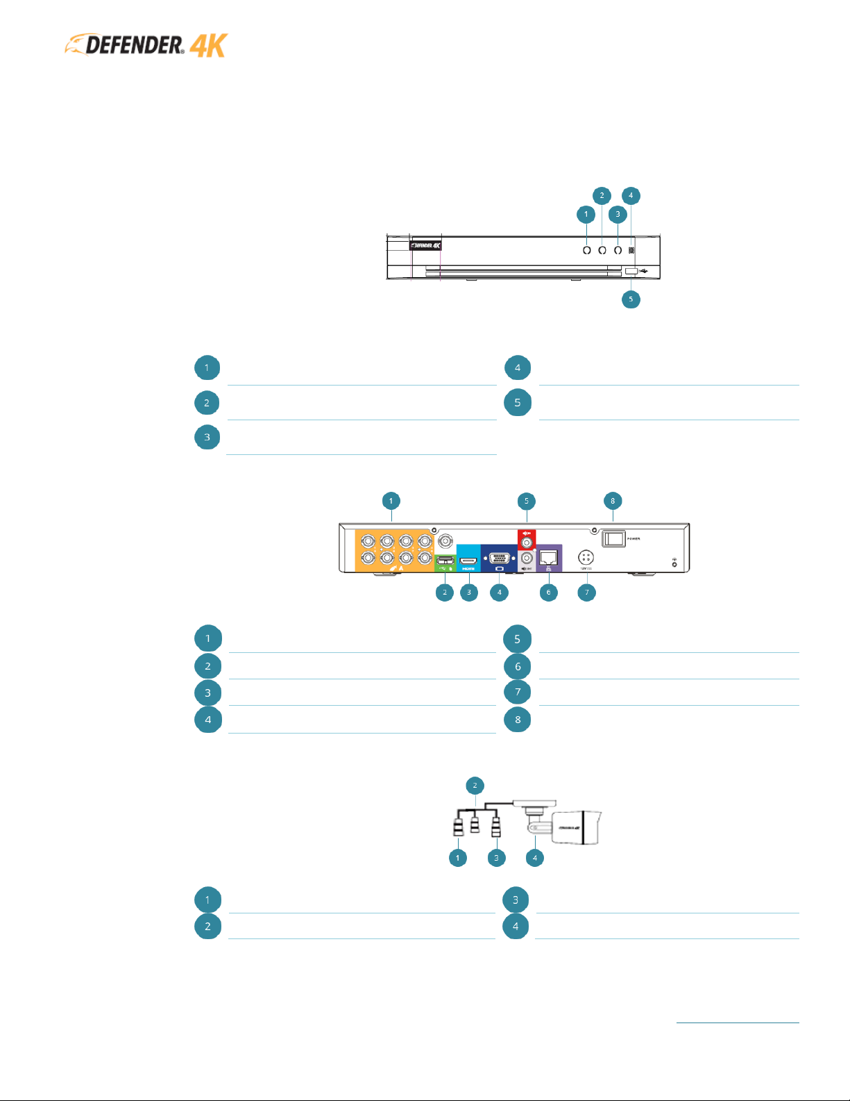
FRONT
Power
(white the DVR is on)
IR Remote Receiver
(remote control not included)
Data
(red data is being imported/exported)
USB Port
Network Connection
(white DVR is connected to a network)
BACK
Video Output (Camera Connections)
Audio IN/OUT
USB Port
Network Port
HDMI Port
Power Input
VGA Port
Power Switch
7.1.2 Camera
Video Output
BNC Connector
Power Input
Locking Screw
The Video Output button is an optional feature used to change the video output of the
camera. You can see the results on the Live View screen.
Page 12
DVR MANUAL
TABLE OF CONTENTS
11
7.2 DVR SETUP
We recommend testing all components and accessories before installing. See section 19 CAMERA
INSTALLATION for details after testing. Setup requires a monitor/TV with an HDMI or VGA connection
(not included).
4K resolution will show only on a 4K monitor/TV. All other monitor/TV types will display
the image in the available resolution.
Before you start:
• You will need a USB flash drive (not included) to save your login & password details during
Activation.
• Check that all components are included in your kit.
• Ensure you have enough power outlets for the monitor/TV, cameras (while testing), and the DVR
unit.
• Setup the DVR near your modem/router – you will need to connect your DVR unit to your
modem/router using the Ethernet cable provided.
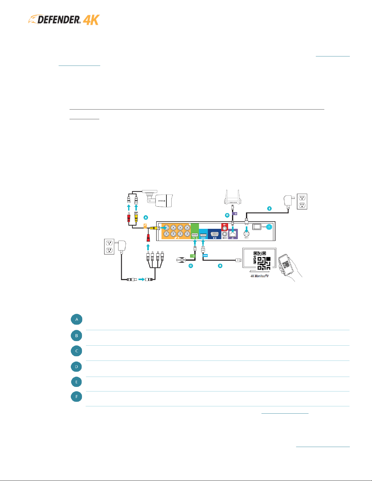
Connections may vary by model
All cables and wires are labeled and color coded to the DVR unit to make connecting your system easier.
1. Connect the monitor/TV, USB mouse, cameras, modem/router, and power to the DVR.
Connect the BMC (YELLOW) connector to the camera and the DVR. Connect the power (RED)
connector to the camera and power source.
Connect the HDMI (AQUA) cable to the DVR and monitor/TV (not included).
Connect the USB mouse (GREEN) to the DVR.
Connect the Ethernet cable (PURPLE) to the RJ45 port on the DVR and your modem/router.
Wired Ethernet connection required – DVR cannot connect to the modem/router via Wi-Fi.
Connect the DVR power adapter to the DVR and a power source.
Turn the DVR power switch ON. Turn on the monitor/TV (not included).
2. Follow the Activation and Setup Wizard to setup the DVR. See section 8 SYSTEM SETUP for details.
Page 13
DVR MANUAL
TABLE OF CONTENTS
12
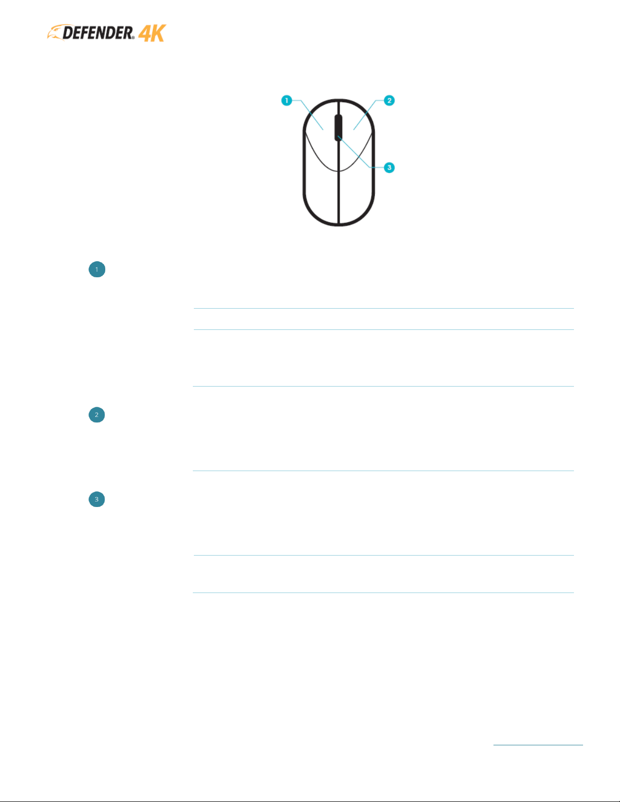
7.3 MOUSE CONTROLS
LEFT BUTTON
SINGLE CLICK
In Live View to select a camera (channel)
DOUBLE CLICK
In Live View to switch between single and multi view screens
CLICK & DRAG
To set Video Tampering, Privacy Mask, and Motion Detect target areas
Moves Zoom area/view
In Live View to move the Channel and Time Bar labels
RIGHT BUTTON
SINGLE CLICK
In Live View to open the Quick Menu
In a Menu to exit to the current screen and return to the previous screen
SCROLL WHEEL
UP
In Live View to view the Previous screen
In Live View when you select Zoom move the scroll wheel to zoom in.
DOWN
In Live View to view the Next screen
In Live View when you select Zoom move the scroll wheel to zoom out.
Page 14
DVR MANUAL
TABLE OF CONTENTS
13
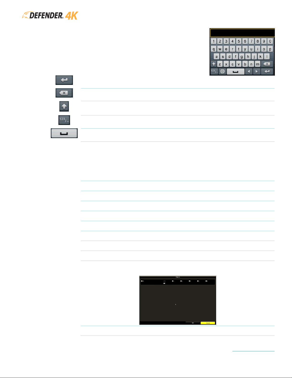
7.4 ON-SCREEN KEYBOARD
To enter information, click (left button) on an input field to open the on-
screen keyboard. This will allow you to select the characters/numbers
using the mouse (left button).
Moves to the next line
Delete/Backspace
Switches the letters between upper/lower case
Switches the keyboard between letters/number/characters
Inserts a space between letters/words
7.1 STANDARD MENU COMMAND BUTTONS
APPLY
Click to apply the changes you have entered. In some case the next screen will appear
and in others the screen will not change but the changes will be applied.
EXIT
Click to close the current screen.
NEXT
Click to move to the next screen.
PREVIOUS
Click to return to the previous screen.
OK
Click to accept the changes or option on the current screen.
CANCEL
Click to exit the current screen without saving any changes.
LIVE VIEW
Click to exit the current screen and return to the Live View screen.
SEARCH
Click to start a Search on a screen.
BACK
Click to return to the previous screen.
COPY
Click to open the Copy option when available. Select the Cameras (Channels) to copy
the current setting to.
ADD
Click to open a new screen to add settings.
Page 15

DVR MANUAL
TABLE OF CONTENTS
14
7.2 ADDITIONAL INFORMATION
• PTZ Cameras are mentioned in the DVR menu – PTZ cameras are not available from Defender for
the 4K system. For PTZ camera instructions refer to the manual provided with your camera.
• IP Cameras are mentioned in the DVR menu – IP cameras are not available from Defender for the
4K system. For IP camera instructions refer to the manual provided with your camera.
• The cameras included in your system do not support sound capture.
Within this manual the following icons are used to callout information:
MENU LOCATION – Because it can be hard to remember where all the Defender 4K Menu
options are located, it is listed at the beginning of each option section.
NOTES – Indicates that an exception or note about the topic.
IMPORTANT – Indicates a callout or important detail about the topic.
• Press CTRL + Click in the Table of Contents to move to the section selected.
• Press CTRL + Click on the Table of Content links on each page to return to the content
page.
Page 16
DVR MANUAL
TABLE OF CONTENTS
15
8 SYSTEM SETUP
8.1 ACTIVATION SCREENS
When the system starts for the first time or when it has been reset to Inactive status, a series of Activation
screens will appear allowing you to setup your Admin Password, Security Questions, and Lock Screen
Pattern. Before you start! YOU WILL NEED A USB FLASH DRIVE TO SAVE YOUR SECURITY SETTINGS.
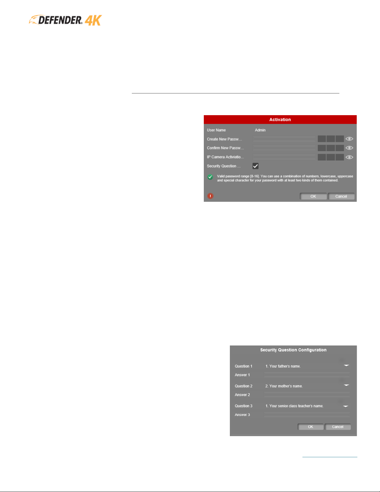
ADMIN PASSWORD
The system does not have a default password,
the first time the system starts you will need to
create a password. This password is required to
access the system and for adding the Device
(DVR) in the mobile app.
The password must be 8-16 characters and must
include at least 2 of the following: numbers,
lowercase / uppercase letters, and special
characters.
We recommend creating a password that is easy to remember but difficult for others to guess and
resetting your password regularly for added protection. REMEMBER YOUR PASSWORD!
STEPS:
• Admin: Create and enter your password. This is the same password you will use when
adding the device (DVR) in the mobile app.
• Confirm: Re-enter your password.
• IP Camera Activation: Create and enter a password. This field is only required for IP Cameras
which are not available from Defender for the 4K system however this field is mandatory to
complete this screen.
• Click the Security Question checkbox to set up the questions. If you forget your password
there are only 2 ways to access your system: Security Questions and GUID Import so we highly
recommend setting up these questions.
• Click OK to set the password and to move to the next screen.
SECURITY QUESTIONS
If you forget your password Security Questions can be
used to verify you are authorized to access the system.
WARNING: DO NOT RIGHT CLICK DURING ACTIVATION
BECAUSE YOU WILL BE UNABLE TO COMPLETE THE
SECURITY QUESTION SECTION. YOU WILL ONLY BE ABLE
TO ACCESS THE SYSTEM USING GUID IF YOU FORGET
YOUR PASSWORD
STEPS:
• Use the drop-down to select from the list of
possible Questions.
• Enter a response in the Answer field.
Page 17

DVR MANUAL
TABLE OF CONTENTS
16
• Repeat for the remaining 2 questions. All 3 questions are
required for this section.
• Click OK to save the questions/answers and to move to the
next screen.
Once you have completed the Security Questions the configuration is complete. Click OK to continue.
EXPORT GUID
We Strongly recommend exporting these settings to a USB flash drive – if you forget your password
and security questions/answers this is the only way to restore access to your system.
This option allows you to export your security settings to a USB
flash drive. If you forget your password the USB can be
inserted into the DVR to confirm your settings. See section 9.3
LOGIN & PASSWORD RESET for details.
STEPS:
• Click YES to open the Export screen.
• INSERT THE USB INTO THE DVR (ADDITIONAL USB PORT)
• The Device Name will show as the USB
• Select the USB device and click Export. See section 9.3 EXPORTING for details.
• If you do not want to export your login details to a USB, click No.
UNLOCK PATTERN
You can setup an Unlock Pattern to access your system. This can
provide a quicker way to access the DVR when it locks during periods
of inactivity.
STEPS:
• Draw a Pattern using the mouse (click & drag). You must
connect at least 4 dots to draw the pattern.
• Re-draw the pattern to confirm.
Page 18

DVR MANUAL
TABLE OF CONTENTS
17
8.2 SETUP WIZARD
The Setup Wizard will take you through a series of basic setup screens to get you started. Once the system
is setup, you can access the Defender 4K Menu from the Live View screen to customize your system and
recording settings.
SIGNAL INPUT STATUS
Select the input type for each channel on the DVR.
This is the type of camera that can be connected to
each channel port.
IP cameras are not available
from Defender for the 4K system.
STEPS:
• Make sure that HD/CVBS is select for each
channel.
• Click Apply to save your selections and to move
to the next screen.
LANGUAGE
Your system supports multiple languages.
STEPS:
• Click the System Language drop-down and
select your desired language.
• Click Apply to save your selection and to move
to the next screen.
WIZARD ACCESS
You can choose to have the Setup Wizard appear each
time the DVR is powered on. This will enable you to
review and/or change these settings on start up.
STEPS:
• Click to select the Start wizard when device start?
checkbox to have the Setup Wizard show each
time the system is turned on. Uncheck the box
to disable this.
• Click Next to save your selection and to move to
the next screen.
Page 19
DVR MANUAL
TABLE OF CONTENTS
18
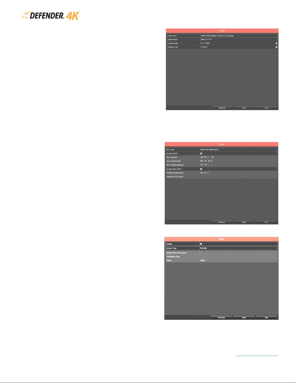
TIME & DATE FORMAT
Select your time zone and date/time format. This is
used on the system and to date/time stamp
recorded footage.
STEPS:
• Click the Time Zone drop-down and select
your zone.
• Click the Date Format drop-down and select
12 or 24 hour.
• Click the System Date calendar icon to select
the current date.
• Click the System Time clock icon to select the
current Hour : Minute : Seconds using the up/down arrows to change the numbers.
• Click Next to save your selections and to move to the next screen.
NETWORK CONNECTIONS
This screen shows the network connections for your
system when the DVR is connected to your
modem/router.
Changes are not required on the screen. Click Next
to move to the next screen.
MOBILE APP ACCESS
This screen controls the access for the Mobile App
to connect to the DVR.
STEPS:
• Click the Enable checkbox to allow the app to
connect to the DVR.
• Create a Verification Code.
This code is
required when adding the DVR in the Mobile
App.
• Click Next to save your entries and to move
to the next screen.
Page 20

DVR MANUAL
TABLE OF CONTENTS
19
• Enter the Verification Code
• You can use the QR Code on this screen to
view the Defender Privacy Policy or you can
view them from www.defender-usa.com
• Click the Service Terms and Privacy
Statement confirmation checkbox to
acknowledge that you have read them.
• Click OK to save your selections and to
move to the next screen.
• Verify the Enable checkbox is selected.
• You can use the QR Code on this screen to
add the DVR on the mobile. We recommend
completing the Setup Wizard before
installing the mobile app. This screen can be
accessed through the Defender 4K Menu
and the QR Code is also attached to the
bottom of the DVR.
• Click Next to move to the next screen.
•
The Status will remain Offline until the
next screen is accessed.
NETWORK PORTS
This screen shows the details and status of the
Network ports.
Changes are only required for advanced users.
Click Next to move to the next screen.
Page 21

DVR MANUAL
TABLE OF CONTENTS
20
DVR HDD
This screen shows the details and status of the
hard drive installed in your DVR.
You can select Init to format the hard drive. This
will remove all exiting files from the hard drive.
Once the formatting process has started it cannot
be stopped and all files will be lost. The DVR hard
drive is pre-formatted and does not require
formatting during setup.
Changes are not required on this screen. Click Next
to move to the next screen.
NETWORK STATUS
This screen shows the details and status of the
modem/router connected to the DVR.
Changes are not required on this screen. Click Next
to move to the next screen.
RECORDING OPTIONS
Select how the DVR will record footage (Continuous
or Motion Detection). The system will record all day
based on the option selected on all cameras
(channels). You can change the recording schedule
at any time from the Defender 4K Menu.
STEPS:
• Click the Continuous field and YES to record
all day on all cameras.
• Click the Motion Detection field and YES to
record only when motion is detected all day
on all cameras.
• Click OK to save your selection.
The Setup Wizard is complete, the Live View screen will open showing the feed from all connected
cameras.
Page 22

DVR MANUAL
TABLE OF CONTENTS
21
9 USING YOUR SYSTEM
9.1 LIVE VIEW
The Live View screen is the main screen on your DVR, from here you can:
❑ Change the camera view options
❑ Use the Toolbar to play recorded footage, zoom in/out on the image, change the image settings,
and more
❑ Access the Quick Access and Defender 4K menus
Active View Window: Move the mouse to ta camera view and click (left button) to select the
camera and to access the Toolbar.
Active View Window Toolbar:
Move the Toolbar to a different location on the Live View screen (click and drag).
Click to Stop/Start Recording.
Page 23

DVR MANUAL
TABLE OF CONTENTS
22
Playback the last 5 minutes of recorded footage. The progress bar will appear
allowing you to move through the footage, pause/re-start playback.
Volume Controls
Defender systems do not support audio recording.
PTZ
PTZ Cameras are not available from Defender for the 4K system.
Zoom IN/OUT.
Open the Image Setting Window (click and drag the slide bars to change the
settings).
VCA Info (click to Show/Hide the VCA settings applied to the selected camera).
Close the Toolbar.
• The other 2 icons on the Toolbar are not available on the Defender 4K
system
• Double click the mouse (left button) to switch between single (camera in
full screen) and multiple camera views.
• Use the scroll wheel on the mouse to view previous (up) cameras or next
(down) cameras.
This will move through all cameras connected to the
DVR when not viewing all.
• Click and Drag a camera view to move it to a different location on the
screen.
Exceptions: Shows when an Exception is reported. Exceptions are setup in DEFENDER
4K MENU > CONFIGURATION > EXCEPTIONS. When enabled and an event occurs the
icon will appear on the screen. Click the icon to view the details.
Alarm: Shows when there is an Alarm setup on the camera.
Recording: Shows when footage is being recorded on the camera. (
example: you have
set the camera to Motion Detection recording and motion is detected by the camera
).
View Window: Depending on the number of cameras connected and the Multi-screen option
selected the live view image of the camera will appear on the screen.
Right Click Menu: Click the mouse (right button) to open the menu.
Page 24

DVR MANUAL
TABLE OF CONTENTS
23
9.2 RIGHT CLICK MENU
FREQUENTLY USED
Select to view a list of screens you frequently visit. Click an option listed to open the screen instead of
opening it through the Defender 4K Menu. This option will not appear until you have opened screens in
the Defender 4K Menu. Once you have opened some of the screens this option will be visible.
DEFENDER 4K MENU
The main menu (Defender 4K Menu) allows you to access the DVR/Camera settings, schedules, features,
functions, and status.
Playback
Search through recorded footage by type, create video clips, tag
footage, and export files.
Export
Export recorded footage from the DVR hard drive to an external
storage device (USB flash drive).
Analytics
This feature only works with IP Cameras (not available from Defender
for the 4K system). Search footage based on analytics.
Manual Camera Setting
Manually change recording setting and run a video diagnostic.
HDD Setting
View the hard drive status and adjust settings.
Video Setting
Set up recording schedules, parameters, and holiday recording
schedules.
Camera Setting
Create camera settings for OSD, image, motion, privacy masks, video
tampering/loss, VCA, and scheduled video diagnostics.
Configuration
Create general system settings including DST, network, live view,
exceptions, and users.
Maintenance
View and adjust system information, logs, import/export, upgrades,
HDD, and defaults.
Shutdown
Shut your system off, reboot or log out.
Page 25

DVR MANUAL
TABLE OF CONTENTS
24
SINGLE SCREEN
Select to change the Live View screen from multiple camera to view only one camera in full screen. Click
the camera from the list of cameras.
You can change the name of each camera to make selecting
easier (example: Driveway, Main Entrance, etc.).
MULTI-SCREEN
Select to change how multiple cameras are displayed on the Live View screen.
The
options will vary depending on the number of channels you have on the DVR (4, 8 or 16).
Click an option and the Live View screen will change.
PREVIOUS/NEXT SCREEN
• Previous Screen: Click to move to the previous view/screen.
• Next Screen: Click to move to the next view/screen.
Page 26

DVR MANUAL
TABLE OF CONTENTS
25
START AUTO-SWITCH
When set the view will switch between cameras (channels). This option will only work when the Dwell
Time is setup in the Defender 4K Menu. See section 14.3.1 LIVE VIEW GENERAL for setting Dwell Times.
This will show the camera view for the selected amount of time before switching to the next camera,
like a slide-show.
START RECORDING
Select between Continuous and Motion Detection recording. This is the same feature that was set during
the Setup Wizard. When selected the system will record all day on all cameras based on your selection.
ADD IP CAMERA
IP Cameras are not available from Defender for the 4K system. To add an IP camera, follow the direction
provided with your camera.
PTZ CONTROL
PTZ Cameras are not available from Defender for the 4K system. Use the PTZ controls on-screen to set
up your camera.
OUTPUT MODE
Output Mode changes the appearance of the image on the screen. Click to select
between the options listed.
This changes the view for all cameras when
selected.
Page 27

DVR MANUAL
TABLE OF CONTENTS
26
9.3 LOGIN & PASSWORD RESET
9.3.1 Login
When the system times out (no activity is detected for a period of time) you will need to either
enter your password or draw the unlock pattern to access the system functions. The Live View will
remain on the screen. You can select to have the system open using the unlock pattern or
password. See section 14.1.1 GENERAL SETTINGS for details.
9.3.2 Password Reset
If you have forgotten your password, click Forgot My Password on either the password or unlock
pattern screens.
Select the Verification Method to open the system by choosing either Verify by GUID or Verify by
Security Question.
SECURITY QUESTION
These are the questions you set up in the Activation section. You will need to remember the
answers to all 3 questions.
Enter the Answers and click OK to unlock the system.
GUID IMPORT
If you selected to save your settings to a USB flash drive in the Activation section, you can use the
USB to unlock the system.
Page 28

DVR MANUAL
TABLE OF CONTENTS
27
Insert the USB into the DVR, select the Device, File, and click Import. The Password Reset screen
will open allowing you to create and enter another password, confirm the password and click OK.
In the Attention pop-up window select OK to export the new password file. The Duplicate
password to the IP Camera password pop-up will appear. Click Yes to update the GUID file.
9.4 SHUT DOWN
RIGHT CLICK MENU > DEFENDER 4K MENU > SHUTDOWN
To shut down the system you have 3 options:
Logout: Closes the current user account and allows for another user to login.
Shutdown: Turns off the DVR.
Reboot: Restarts the DVR.
Page 29

DVR MANUAL
TABLE OF CONTENTS
28
9.5 RESTORING SYSTEM DEFAULTS
RIGHT CLICK MENU > DEFENDER 4K MENU > MAINTENANCE > DEFAULT
Select to restore defaults (settings), set factory defaults or restore to inactive. There is no confirmation
screen for these options. Once our click the action will occur.
If you have missed setting up your
Security Questions during Activation, you can click Factory Default to start the Activation setting again.
Page 30

DVR MANUAL
TABLE OF CONTENTS
29
10 PLAYBACK
RIGHT CLICK MENU > DEFENDER 4K MENU > PLAYBACK
From this screen you can view all recorded footage. Features include viewing, creating clips, assigning tags, and
exporting footage to an external storage device.
Type: Use the drop down to select the type of playback. Choose between:
• Normal – all normal footage will appear in the list
• Event – all event footage will appear in the list
• Tag – only tagged footage will appear in the list
• Smart – shows footage in fast forward (skips to action)
• Sub-periods – shows a grid of footage for cameras with different time stamps
• External Files – shows all files located on a USB flash drive
Use the other drop-down to select between Main Stream and Sub Stream footage.
• Main Stream – higher steam resolution and frame rate.
• Sub Stream – low/standard stream resolution for lower bandwidth situations (
example: high
internet traffic can cause lower bandwidth
)
Playback Timeline: The date and time stamp of the footage appears in this area. Use the progress bar
(click and drag) to move through the recorded footage. Use the Arrow buttons to the right to Zoom
IN/OUT on the timeline.
Video File Management:
Page 31

DVR MANUAL
TABLE OF CONTENTS
30
A. Clip (Start/Stop): Create a Clip of part of the recorded footage. While playing the footage click the
button to start creating a clip and again to stop.
B. Lock File: Click to Lock the file so that it cannot be overwritten or recorded over.
C. Add Default Tag: Click to assign a default tag to the footage. Tags make searching for footage
easier. When selected the footage will be named TAG.
D. Add Customized Tag: Click to enter a custom tag to give the footage a name of your choice.
• Click the Tag Name field to enter the tag and click OK to save. You can add multiple tags to a
video file
E. File Management: Click to Export files to an external storage device.
To Export files, you will
need to insert a USB flash drive into the USB port on the DVR. The files will export to this device.
• Use the Tabs on the top of the screen to select the type of files to export (Videos, Locked files
or Tagged files)
• Select the Footage listed on the screen by clicking the checkbox
• Select Export All to export all files listed
• Select Export to export only the selected files
• Select Cancel to exit the File Management screen without exporting files
F. Zoom IN: Click to zoom in on the footage. Click and drag to select an area of the screen to zoom
in on.
Video Playback Controls:
Page 32

DVR MANUAL
TABLE OF CONTENTS
31
A. Reverse Playback / Play / Stop / Pause
B. Rewind / 30s Rewind / Fast Forward / 30s Fast Forward
C. View Previous / Next
• Normal mode will change by day
• Event mode will change by event
• Tag mode will change by tag
Event Type: This shows the type of recorded footage on the Timeline.
• Normal – footage will appear in blue as a line on the Timeline
• Event – footage will appear in red as a line of the Timeline
Calendar: When a date is highlighted on the calendar it indicates that recorded footage is available.
Double click a date to select.
Camera List: Click the checkbox beside the camera names to select and search footage from one or
more camera.
11 EXPORT
Use this section to export recorded footage from the DVR HDD to an external storage (USB flash drive). You
MUST connect a USB flash drive to the DVR using the additional USB port before you can export files.
11.1 NORMAL
Allows you to search all regular type footage to select for export.
1. Click the checkbox to select the Cameras in the Analog section. These cameras will be included
when searching for footage.
2. Click the Record Mode drop-down to choose between Main Stream and Sub Stream recorded
footage.
Page 33

DVR MANUAL
TABLE OF CONTENTS
32
3. Click the Recording Mode drop-down to narrow the amount of footage to a specific type (
example:
select motion if you only want to export footage recorded when motion was detected
) or select All
to include all types of recorded footage.
4. Click the File Type drop-down to narrow the amount of footage to a specific type (
example: select
locked if you only want to export footage you have locked on the Playback screen
) or select All to
include all file types.
5. Click the calendar icons to select a date range in the Start Time/End Time fields. This allows you to
export only the footage recorded between the dates selected.
6. Click the time icons to select a time frame for the dates selected in the Start Time/End Time fields.
Enter the Hour : Minutes : Seconds using the up/down arrows. This allows you to export only the
footage recorded during the time frame selected (
example: you may only want to export footage
recorded after 5 PM and before 7 AM
).
7. Click Search to view the list of available footage to export.
File List: Click the checkbox beside each recorded file to select it for export.
Preview Section: Click on a file to view it in the preview window. Use the Preview Controls
to view the footage to Stop/Play/Show Previous/Show Next.
Select the List tab at the top of the screen to show a list of the recorded footage. This view also
shows the file details.
8. Select Export All to export all files listed.
9. Select Export to export the selected files only.
10. Select Cancel to exit the screen without exporting files.
Page 34

DVR MANUAL
TABLE OF CONTENTS
33
11.2 EVENT
Use this section to search all Event type footage to select for export.
1. Click the drop-down to select the Major Type. Choose from the options (Motion, Alarm Input or
VGA) for the type of file to export.
2. Click the drop-down to select the Record Mode. Choose between Main Stream and Sub Stream
recorded footage.
3. Click the calendar icons to select a date range in the Start Time/End Time fields. This allows you to
export only the footage recorded between the dates selected.
4. Click the time icons to select a time frame for the dates selected in the Start Time/End Time fields.
Enter the Hour : Minutes : Seconds using the up/down arrows. This allows you to export only the
footage recorded during the time frame selected (
example: you may only want to export footage
recorded after 5 PM and before 7 AM
).
5. Use the checkbox to select the Cameras in the Analog section. These cameras will be included
when searching for footage.
6. Click Search to view the list of available footage to export. Select the footage to be exported from
the options listed on the search results screen.
Page 35

DVR MANUAL
TABLE OF CONTENTS
34
11.3 EXPORTING
Once you have selected footage to export you can select to either export the selected footage or all
footage.
1. Insert a USB flash drive into the DVR (additional USB port). Ensure there is enough space on the
USB to hold the video/image files. The USB size is dependent on the number of files you plan to
export.
2. Use the drop-down to select the Device Name.
The USB name should appear automatically, you
will only need to do this if you have multiple devices (example USB flash drive or HDD).
3. The list of folders and file on the USB will appear in the list widow. Double click on a folder to have
the files save to it or click the Delete icon to remove a folder from the USB.
4. The File Type is automatically populated (*.mp4;*.zip) and includes a Player for the files when
viewing on a PC.
5. You can select New Folder to change the export location on the external storage device. Click the
Name field to enter a name for the folder. Click OK to add.
6. You can also Format the external storage device by clicking Format.
Once select format all data
will be lost and cannot be recovered.
7. Click Export and choose Video & Files to copy the files from the DVR to the storage device. Once the
files have been exported a confirmation pop-up window will appear. Click OK.
Page 36

DVR MANUAL
TABLE OF CONTENTS
35
11.4 PLAYING FOOTAGE
This section covers how to play footage on a PC. The Player exported with the files is not supported for
Mac users. To download a Player, visit our website at www.defender-usa/support. The process for both
PC and Mac users is similar once you have the Player.
Once the files have been exported to the USB, remove it from the DVR and insert it into your computer
and open the folder.
When you open the folder, the files were exported to you will see the Player folder, a file for each
footage you selected, and a text file with the details for each file.
1. Double click on the player folder to open.
2. Click Player to open the media player app.
3. Select the File to play:
Drag & Drop
• With both the Player and Folder windows open
Page 37

DVR MANUAL
TABLE OF CONTENTS
36
• Click and drag the file name to the Player window – the file will open in the Player.
Open File
• For the Player window click File > Open.
• Click to select the file name and click Open.
Page 38

DVR MANUAL
TABLE OF CONTENTS
37
12 VIDEO RECORD SETTINGS
Video settings allow you to setup recording schedules, parameters, and holiday recording schedules.
12.1 SCHEDULE
RIGHT CLICK MENU > DEFENDER 4K MENU > VIDEO SETTINGS
View the current recording schedule by camera. You can see when (day/time) all types of recordings are
scheduled for the selected camera.
Schedule Types
CONTINUOUS
Set to record footage always on the selected camera. When set this overrides Motion
and Alarm settings.
EVENT
Set to record footage only when an event occurs.
MOTION
Set to record footage only when motion is detected.
ALARM
Set to record footage only when an alarm is activated.
M | A
Set to record footage only when motion OR alarms are detected.
M & A
Set to record footage only when motion AND alarms are detected.
1. Use the Camera drop-down to select a camera from the list.
This will show the current schedule
for the selected camera.
Changes made to the schedule will apply to the camera selected only.
2. Click the Recording Type and click a time block (or click and drag to select multiple time blocks) or
Click the Enable Schedule checkbox to apply the schedule.
3. Click Edit to change the current schedule.
Page 39

DVR MANUAL
TABLE OF CONTENTS
38
A. Use the Weekday drop-down to select a day of the week.
You can use the Copy function to
select the same schedule for multiple or all days of the week.
B. Click the All Day checkbox to apply the schedule to all times of the day or click the Time icon
and enter the Hour : Minutes : Seconds using the up/down arrows.
C. Use the Type drop-down to select the type of recording.
You can select different recording
types for different times of the day.
D. Click Apply to save your settings.
E. Click OK to save all changes and exit the Edit screen.
4. You can select Copy (on the Schedule screen) to apply this schedule to other cameras.
5. Click Apply to save the new schedule settings.
12.2 PARAMETERS
RIGHT CLICK MENU > DEFENDER 4K MENU > VIDEO SETTINGS
The settings on the Record and Sub stream tabs are set to default values and do not need to be changed
for regular option of your system.
Camera
These setting apply to the camera selected.
Page 40

DVR MANUAL
TABLE OF CONTENTS
39
Camera Resolution
Adjusts the video resolution and frame rate on the camera.
Encoding Parameters
Main Stream settings for Continuous and Event recordings. Encoding is the
process of preparing the video for output. Video is encoded to meet proper
formats and specifications for recording and playback.
Stream Type
Audio recording is not available on Defender cameras. Video should be
selected for this setting.
Resolution
Adjusts the video resolution setting recorded by the camera.
Bitrate Settings
Adjusts the bitrate settings on the camera.
Video Quality
This setting affects the amount of space recorded footage uses on the hard
drive. If the setting is increased it will reduce recording time and footage
will take up more space on the hard drive.
Frame Rate
Adjusts the number of frames per second the DVR will record.
Video Encoding
Adjusts the encoding method used for the selected camera.
Enable H265+
When enabled the DVR will compress the video to the maximum
compression rate (H.265) and will ensure optimal video quality. This will
increase the recording space available on the DVR.
MORE SETTINGS
1. Use the Pre-record drop-down to select the amount of time the DVR will record before a scheduled
time or event occurs. (
example: if the schedule is set to start recording at 10:00 AM and you select
5 seconds – the DVR will start recording at 9:59:55
).
2. Use the Post-record drop-down to select the amount of time the DVR will record after a scheduled
time or event occurs. (
example: if the schedule is set to stop recording at 10:00 AM and you select 5
seconds – the DVR will stop recording at 10:00:05
).
3. Click the Expired Time (day) field to enter the number of days a recording will be kept on the hard
drive before the file will be deleted. The default is set to 0 which means the recording will not be
deleted and the footage will be kept until it is manually deleted or the system overrides the footage
based on your settings.
4. Use the Video Stream drop-down to select between Main and Sub Stream for this setting.
5. Click OK to save your settings.
Page 41

DVR MANUAL
TABLE OF CONTENTS
40
12.3 ADVANCED
RIGHT CLICK MENU > DEFENDER 4K MENU > VIDEO SETTINGS
The advanced setting allows you to select the correct action when the hard drive is full.
Click the Overwrite checkbox to enable the DVR to record over the oldest footage when the disk is full. If
not selected the DVR will stop recording when the hard drive is full and will report HDD Full as an event
based on your exception settings. See section 14.4 EXCEPTIONS for details.
12.4 HOLIDAY
You can setup breaks in the recording schedule using the Holiday function. When a holiday is setup the
system will stop recording during the dates/times entered and will resume when the holiday is over.
Holidays will override the regular Schedule setup.
RIGHT CLICK MENU > DEFENDER 4K MENU > VIDEO SETTINGS
1. Select a Holiday from the list and click the Edit checkbox.
2. Click the Enable checkbox to apply the holiday to the schedule.
3. Use the Mode drop-down to select how often the holiday will repeat.
4. Use the Start/End Date drop-downs to select the holiday date range.
5. Click Apply to save the new settings.
Page 42

DVR MANUAL
TABLE OF CONTENTS
41
6. Click OK to exit the Edit screen.
13 CAMERA SETTINGS
13.1 CAMERA
Signal Input Status is used to choose the allowable input type for each channel on the DVR. This is the
type of camera that can be added to each channel port. This should only be HD/CVBS for all channels
because IP cameras are not currently available from Defender for the 4K system. This screen is part of
the Setup Wizard.
13.2 OSD (ON-SCREEN DISPLAY)
RIGHT CLICK MENU > DEFENDER 4K MENU > CAMERA SETTINGS
These settings allow you to adjust the on-screen display for each camera including what will be displayed,
camera names, and formats. Change made will appear in the preview window on this screen.
1. Use the Camera drop-down to select a camera to adjust.
2. Click the Camera Name field to enter a new name.
Giving the camera a descriptive name will
make it easier when selecting the camera (example: driveway, front entrance, etc).
3. Click the Display Name checkbox to have the name appear.
4. Click the Display Date checkbox to have the date appear.
5. Click the Week checkbox to have the week appear.
6. Use the Date Format drop-down to select how the date will appear.
7. Use the Time Format drop-down to select the type of clock (12 or 24 hour).
8. Use the Display Mode drop-down to select the appearance type (how the on-screen display will
show on the screen). Choose if the OSD should flash and/or be transparent on the screen.
9. Use the OSD Font drop-down to select the size of the font.
10. Click Apply to save these settings to the current camera.
11. Click Copy to apply these settings to other cameras.
If you have entered a name for this camera
it will also be copied to the other camera(s).
Page 43

DVR MANUAL
TABLE OF CONTENTS
42
13.3 IMAGE
RIGHT CLICK MENU > DEFENDER 4K MENU > CAMERA SETTINGS
Use this section to change the image settings for each camera.
13.3.1 Image Settings
1. Use the Camera drop-down to select a camera.
2. Use the Time Segment time icon to select a time frame the settings will be applied to.
Select the Start/End Hour : Minute using the up/down arrows.
The default is set to all
day however depending on the location of the camera you may need to adjust the settings
for a specific time of day to ensure a clear image.
3. Use the Mode drop-down to select the mode that best fits the location of the camera
(
example: if the camera is located under an overhang, you might want to select Dim Light
).
4. Use the slide bar or up/down arrows to adjust the Image Settings.
You can see the
results in the preview window.
5. Click Apply to save these settings or Default to return to the original settings.
6. Use the Copy function to apply these settings to other cameras.
The image settings
requirements may not be the same for all camera locations.
Page 44

DVR MANUAL
TABLE OF CONTENTS
43
13.3.2 Camera Parameter Settings
1. Use the Camera drop-down to select a camera.
2. Use the slide bar or up/down arrows to adjust the sensitivity level when switching between
Day to Night and Night to Day.
3. Use the slide bar or up/down arrows to adjust the brightness of the IR Lights on the
camera.
4. Use the Day/Night Mode drop-down to select how night vision will be enabled. You can
select the camera to always use day or night mode or automatically adjust based on the
illumination conditions of the camera location.
5. Click Apply to save these settings or Default to return to the original settings.
6. Use the Copy function to apply these settings to other cameras.
The parameter
requirements may not be the same for all camera locations.
Page 45

DVR MANUAL
TABLE OF CONTENTS
44
13.4 MOTION
RIGHT CLICK MENU > DEFENDER 4K MENU > CAMERA SETTINGS
This section allows you to set up area to exclude from motion detection. This can be helpful to block out
areas that may trigger unnecessary recording (
example: background traffic areas
).
1. Use the Camera drop-down to select a camera.
2. Click the Enable Motion Detection checkbox to allow for motion only recording.
3. Click Setting:
• Pre-record: The number of seconds the DVR will record before the motion event occurs
• Post-record: The number of seconds the DVR will record after the motion event occurs
4. Use the slide bar to set the Sensitivity for how much motion needs to be detected to trigger
recording.
The greater the sensitivity (closer to the right side) the more sensitive to motion the
system will be.
5. Click and drag the mouse within the preview window to set the areas where motion will not be
detected.
• Red grid areas indicate motion will trigger recording
• Clear areas indicate motion detected will not trigger recording
6. Click Full-screen to view the preview window in full screen to select motion areas.
7. Click Clear to remove all motion areas.
8. Click Apply to save these settings.
9.
Use the Copy function to apply these settings to other cameras
The motion detect areas may
not be the same for all cameras.
Page 46

DVR MANUAL
TABLE OF CONTENTS
45
13.5 PRIVACY MASK
RIGHT CLICK MENU > DEFENDER 4K MENU > CAMERA SETTINGS
This section allows you to set areas that will not be recorded.
1. Use the Camera drop-down to select a camera.
2. Click the Enable Privacy Mask checkbox to allow for privacy areas to be applied.
3. Click and drag the mouse within the preview window to set the areas that will not be recorded. You
can set up to 4 areas for each camera. Areas that are blocked out will not be recorded.
4. Click the Clear All or Clear Zone 1-4 buttons to remove areas that have been set.
5. Click Apply to save these settings.
6. Use the Copy function to apply these settings to other cameras.
The privacy areas may not be
the same on all cameras.
Page 47

DVR MANUAL
TABLE OF CONTENTS
46
13.6 VIDEO TAMPERING
RIGHT CLICK MENU > DEFENDER 4K MENU > CAMERA SETTINGS
This section allows you to set parameters for system alerts when a camera has been tampered with.
1. Use the Camera drop-down to select a camera.
2. Click the Enable Video Tampering Detection checkbox to allow for detection.
3. Click the Settings to apply an action when the DVR detects tampering on the camera.
4. Use the slide bar to set the Sensitivity level for tampering detection.
The greater the sensitivity
(closer to the right side) the more sensitive to motion the system will be.
5. Click Apply to save these settings.
6. Use the Copy function to apply these setting to other cameras.
Page 48

DVR MANUAL
TABLE OF CONTENTS
47
13.7 VIDEO LOSS
RIGHT CLICK MENU > DEFENDER 4K MENU > CAMERA SETTINGS
This section allows you to set parameters for the system to alert when a camera has lost connection with
the DVR.
1. Use the Camera drop-down to select a camera.
2. Click the Enable Video Loss Alarm checkbox to all for loss detection.
3. Click Settings to apply an action when the DVR detects video loss on the camera.
4. Click Apply to save these settings.
5. Use the Copy function to apply these settings to other cameras.
Page 49

DVR MANUAL
TABLE OF CONTENTS
48
13.8 VCA
RIGHT CLICK MENU > DEFENDER 4K MENU > CAMERA SETTINGS
VCA allows you to setup rules for areas that will detect when an action has occurred (
example: setup an
area on the camera to detect when motion crosses into the area
). The following settings will work with
your wired cameras:
LINE CROSSING DETECTION
Set a line on the camera image with a rule that if something
crosses the area an event will occur.
INTRUSION DETECTION
Set an area on the camera image with a rule that if something
enters the area an event will occur.
SUDDEN SCENE CHANGE DETECTION
Set a rule that if there is a sudden change on the camera image
an event will occur.
The remaining setting will only work on an IP Camera (not available from Defender for the 4K system).
1. Use the Camera drop-down to select a camera.
2. Click the Save VCA Picture to enable the system to take a snap shot of the event.
This will occur
when an event is detected (example: something enters an area that is setup as a rule).
3. Click the Enable checkbox to turn VCA detection on.
4. Click Settings:
• Trigger Channel: Select the cameras to include in the settings
• Arming Schedule: Select the days/time for monitoring
• Linkage Action: Select the action the system should perform when an event occurs
5. Use the Rule drop-down to select the rule number.
6. Click the Rule Setting button to enter details. Set the Direction (action that happens to create the
event – crossing from area A to B) and Sensitivity (how much motion needs to occur) for motion
within the set area.
7. Use the Draw Line or Draw Quadrilateral functions to create an area for detection. When
something enters the area, an event will occur.
Page 50

DVR MANUAL
TABLE OF CONTENTS
49
8. Use Clear All to remove areas.
9. Click Apply to save these settings to the camera selected.
13.9 VIDEO QUALITY DIAGNOSTICS
RIGHT CLICK MENU > DEFENDER 4K MENU > CAMERA SETTINGS
This section allows you to set parameters for the quality of the video from each camera. When a
diagnostic is run on the camera these parameters will be used to determine quality issues.
1. Use the Camera drop-down to select a camera.
2. Click the Enable Video Quality Diagnostics checkbox to all for diagnostics on the camera.
3. Click Settings to set the date/time and action for the diagnostics to run and action for the results:
Arming Schedule
A. Use the Week drop-down to select when the diagnostics will run.
B. Use the Time icon to set a time for running the diagnostics.
It is recommended to run this
during the day.
C. Use the Copy function to apply these settings to other days of the week or everyday.
D. Click Apply to save these settings.
Linkage Action
A. Click the checkboxes to assign an Action for the results.
B. Click Apply to save these settings.
4. Use the slide bar or up/down arrows to assign a Threshold for acceptable quality on the camera
view.
5. Click Apply to save these settings.
6. Use the Copy function to apply these setting to other cameras.
The video quality may be
different for each camera depending on the location.
Page 51

DVR MANUAL
TABLE OF CONTENTS
50
14 CONFIGURATION
14.1 GENERAL
RIGHT CLICK MENU > DEFENDER 4K MENU > CONFIGURATION
14.1.1 General Settings
Some of the settings on this screen where set in the Setup Wizard. You can change these settings
from this screen.
1. Use the Language drop-down to change the language of the menus and screens.
2. Use the VGA/HDMI Resolution drop-down to change the resolution of the monitor/TV being
used. The DVR will automatically set the resolution. This setting does not need to be
changed.
3. Use the Time Zone drop-down to change.
4. Use the Date Format drop-down to change the format for how the date is displayed on the
screen and in recorded footage.
5. Use the calendar icon to change the System Date.
6. Use the time icon to change the System Time.
7. Use the slide bar to adjust the speed of the Mouse Pointer.
As you move the slide bar the
mouse response will change on the screen.
8. Click the Enable Wizard checkbox to have the Setup Wizard launch each time the DVR is
powered on.
9. Click the Enable Password checkbox to have the password required when the DVR screen
locks after a period of inactivity.
10. Click to Apply to save these settings.
Page 52

DVR MANUAL
TABLE OF CONTENTS
51
14.1.2 DST Settings
Use this section to set the DVR to automatically adjust for daylight saving time (DST). Based on
these settings the system time will change at the start of DST and change back at the end.
1. Click the Auto DST Adjustment checkbox to have the DVR automatically adjust the system
time for DST based on the local DST rules.
This will only work if the DVR is connected to
your modem/router.
2. Click the Enable DST checkbox to have the DVR adjust the system time based on the
day/times entered.
3. Use the Month, Day #, Day drop-downs to select the Start (From)/End (To) time frames for
DST.
4. Click the Time fields to enter the start/end time for DST (time of day DST starts and ends).
5. Use the DST Bias drop-down to select the time difference or number of minutes/hours the
time should adjust for the start/end of DST.
6. Click Apply to save these settings.
Page 53

DVR MANUAL
TABLE OF CONTENTS
52
14.1.3 More Settings
1. Click the Device Name field to change the name of the DVR or leave it as the default. The
Device No. is the internal device number of the DVR.
2. Use the Auto Logout drop-down to select the number of minutes before the DVR locks out
the menu functions showing only the Live View screen.
The DVR will require either the
password or unlock pattern to re-open the menu once it has locked.
3. Use the Menu Output Mode drop-down if you have more than one display connected to the
DVR to select which display will show the Menu and Toolbar (VGA or HDMI).
4. Click Apply to save these settings.
14.2 NETWORK
RIGHT CLICK MENU > DEFENDER 4K MENU > CONFIGURATION
GENERAL
This section is covered in the Setup Wizard section. The settings on this screen do not need to be changed
they are automatically assigned by your network when the Enable DHCP checkbox is selected and the
NIC Type default should not be changed for regular use of the DVR.
APP ACCESS
This section is covered in the Setup Wizard section. The Enable checkbox must be selected for the Mobile
App connection to work. You can change the Verification Code from this screen if needed. The Verification
Code is required when setting up a Mobile App Account.
PPPOE
This is an advanced setting. Contact your Internet service provider for details about PPPOE services.
DDNS
Enable the DDNS service to view your DVR from a computer. Contact your Internet service provider to
setup.
NTP
Allows you to setup your DVR to obtain the current date and time from our network. The Enable NTP
checkbox needs to be selected to allow the DVR to be updated. Interval (min) is the number of minutes
Page 54

DVR MANUAL
TABLE OF CONTENTS
53
that will elapse for the internal clock on the DVR to update to match the NTP server – 60 minutes is
recommended.
NAT
This is an advanced setting and should not be changed for regular use of the DVR.
MORE SETTINGS
These are advanced settings and should not be changed for regular use of the DVR.
14.2.1 Email
Allows you to set up addresses for system notifications. This is an advanced setting and is not
required for regular use of the DVR.
1. Click the Enable Server Authentication checkbox if your outgoing mail server requires
authentication. If selected enter the User Name and Password for the outgoing mail server.
2. Enter the Sender name (name that will identify the sender).
3. Enter the Sender’ s Address (your email address connected with the system).
4. Enter the SMTP Server and SMTP Port of your email service provider.
Find your email
provider’s server address and port by typing SMTP settings followed by the name of your
email provider in your Internet browser (example: SMTP settings Gmail).
5. Click the Enable SSL/TLS if your service provider requires a secure link.
6. Use the Select Receivers drop-down to select up to 3 recipients for DVR notifications.
7. Enter the Receiver name.
Page 55

DVR MANUAL
TABLE OF CONTENTS
54
8. Enter the Receiver Address (email address of the recipient).
9. Repeat steps 6 – 8 for each email contact (receiver).
10. Click the Enable Attached Picture checkbox to allow the DVR to send a small image for each
alert (this will attach for recorded footage notification only).
If the email is related to a
motion alert the image will be of the object that triggered the alert only).
11. Use the Interval drop-down to select the amount time that needs to pass after sending an
email before another email can be sent.
12. Click Test to send an email to the receivers.
13. Click Apply to save these settings.
14.3 LIVE VIEW
14.3.1 General
RIGHT CLICK MENU > DEFENDER 4K MENU > CONFIGURATION
1. The Video Output default is VGA/HDM and does not need to be changed.
2. Use the Live View Mode drop-down to select a default screen view (number and positioning of
cameras shown on the screen).
3. Use the Dwell Time drop-down to select the number of seconds a video will stay on the screen
before switching to the next camera.
This setting is required before Auto-switch can be selected
from the Right Click Menu.
4. Audio Output and Volume are not supported on the Defender 4K systems.
5. The Event Output default is VGA/HDMI and does not need to be changed.
6. Use the Full Screen Monitoring Dwell Time drop-down to select the amount of time the alarm event
window will be displayed.
7. Click Apply to save these settings.
Page 56

DVR MANUAL
TABLE OF CONTENTS
55
14.3.2 View
View allows you to set up the default position of the cameras on the Live View screen. This option can be
changed from the Live View screen using the Right Click Menu > Multi-screen or Single Screen.
1. Use the Video Output Interface drop-down to select VGA/HDMI (DVR monitor) or Channel-Zero (App).
2. Click one of the Screen Layout options from the Toolbar below the preview screens.
3. Click and drag a Camera from the list to the widow it should appear in.
4. Click Apply to save these settings.
14.3.3 Channel-Zero Encoding
Click the Enable Channel-Zero Encoding checkbox to allow the remote viewing of many camera views
(channels) in real-time on the app to decrease the bandwidth requirements without affecting the image
quality.
The defaults on this screen should not be changed for regular use of the system. The Enable Channel-Zero
Encoding checkbox should be checked.
Page 57

DVR MANUAL
TABLE OF CONTENTS
56
14.4 EXCEPTIONS
RIGHT CLICK MENU > DEFENDER 4K MENU > CONFIGURATION
5. Click the Enable Event Hint checkbox to turn on hints on the Live View screen. When a hint is
available the triangle icon will appear on the camera view (bottom right corner). Click the icon to
open the details.
6. Select the Event Hint Settings for the type of events and exceptions that will trigger the icon display.
7. Use the Exception Type drop-down to select an exception that will trigger an event (
example: HDD
Full, HDD Error, Network Disconnected, etc
).
8. Click the Audible Warning checkbox to enable a continuous audible beeping that can be heard
from the DVR when an event or exception occurs.
9. Click the Send Email checkbox to enable an alert email to be sent based on your Email Notification
settings. See section 14.2.1 EMAIL for details on setting up email alerts.
10. Click Apply to save these settings.
Page 58

DVR MANUAL
TABLE OF CONTENTS
57
14.5 USER SETUP
RIGHT CLICK MENU > DEFENDER 4K MENU > CONFIGURATION
1. You can click Edit to change user details like name, password and rights. Click OK to save changes.
Select Delete to remove a user.
2. Click Add to create a new user account:
A. Click the User Name field to enter a login name.
B. Click the Password field to create a password for the user.
The same password criteria used
to set up your password applies to all users
.
C. Click the Confirm field to re-enter the password.
D. Use the Level drop-down to select the type of user:
• Guest: User will be able to see the Live View screen and Playback recorded footage.
• Operator: User will be able to access all camera operations (including Playback and
Exporting) and they will have limited access to most menu functions.
Operators are not
able to change the DVR or Camera settings.
E. If the User’s MAC Address is entered, they will be able to access the DVR remotely only from
the computer using that MAC Address.
F. Click OK to add the user.
Page 59

DVR MANUAL
TABLE OF CONTENTS
58
15 MANUAL CAMERA SETTINGS
This section allows you to manually adjust recording options and perform a diagnostic on the video quality. The
Alarm section will not work on this system because the DVR is not equipped to allow for an alarm to be attached.
15.1 RECORD
RIGHT CLICK MENU > DEFENDER 4K MENU > MANUAL CAMERA SETTINGS
1. Click the ON icon beside Analog (all cameras) or beside each camera to turn off recording – click
again to turn recording back on.
2. Click the ON icon beside Recording by schedule to disable the ability to record based on the
schedule on the selected cameras – click again to turn this feature back on.
3. Click the ON icon beside Recording by manual operation to disable the ability to select record
(manually from the Live View screen) on the selected cameras – click again to turn this feature back
on.
4. Click the Continuous icon to select to record all the time on the selected cameras – this will override
scheduled recording if set up for the selected cameras.
5. Click the Motion Detection icon to select to record only when motion is detected on the selected
cameras.
Page 60

DVR MANUAL
TABLE OF CONTENTS
59
15.2 MANUAL VIDEO QUALITY DIAGNOSTICS
RIGHT CLICK MENU > DEFENDER 4K MENU > MANUAL CAMERA SETTINGS
This feature allows you to run a video quality diagnostic manually on any or all cameras connected to the
DVR. The criteria for good quality is setup on the Video Quality Diagnostics screen. When the criteria is
set you can also setup a schedule for when this diagnostic should run automatically.
1. Click the Analog checkbox to select all cameras or select specific Cameras.
2. Click the Diagnose button to begin the check – the system will check based on the criteria assigned
on the Video Quality Diagnostics screen. See section 13.9 VIDEO QUALITY DIAGNOSTICS for details.
3. The Results will show on the screen indicating whether the quality settings have been
compromised.
Page 61

DVR MANUAL
TABLE OF CONTENTS
60
16 HDD SETTINGS
16.1 HDD INFORMATION
Provides the status of your hard drive and allows you to edit some details (
example: name
).
RIGHT CLICK MENU > DEFENDER 4K MENU > HDD SETTING
1. Click Edit to allow for hard drive details to be changed.
2. Click Delete to remove a hard drive from the DVR.
This is advance function and is not required
for regular use of the system.
3. Click Add if you have installed an additional hard drive in your DVR.
This is advance function and
is not required for regular use of the system.
4. Click Init to format the hard drive.
Formatting the hard drive will erase all recorded data. Once
formatting is started it cannot be stopped or undone.
Page 62

DVR MANUAL
TABLE OF CONTENTS
61
16.2 ADVANCED
RIGHT CLICK MENU > DEFENDER 4K MENU > HDD SETTING
1. Use the Mode drop-down to select:
• Quota – Configure each camera to have a maximum quota for storage of recorded files or
picture capture. This will limit the amount of hard drive space the camera is allowed to use.
Leave the Max. fields at 0 to allow each camera to share the available space on the hard drive.
• Group – If you have multiple HDD installed they can be managed in groups. Video from
selected cameras can be recorded to a specific HDD through these settings.
2. Use the Camera drop-down to select.
3. When using Quota, you can change the Max. Record Capacity (GB) and Max. Picture Capacity (GB)
for each camera – the default is 0 which means all cameras will share the total capacity of the hard
drive.
4. Click the Enable HDD Sleeping to switch the status and reduce the storage consumption when
there is no need to read or write to the HDD.
5. Click Apply to save your settings.
6. You can select Copy to apply these setting to other cameras.
Page 63

DVR MANUAL
TABLE OF CONTENTS
62
17 SYSTEM MAINTENANCE
17.1 SYSTEM INFO
RIGHT CLICK MENU > DEFENDER 4K MENU > MAINTENANCE
The system info section provides details about your Device, Cameras, Recordings, Alarms, Network, and
hard drive (HDD). Open these screens to view the status of these functions.
In the Device section you can click the Check Update button to see if there is a Firmware Version update
for your device.
17.2 LOG INFORMATION
RIGHT CLICK MENU > DEFENDER 4K MENU > MAINTENANCE
Allows you to view and export all activity logs captured by the system. The DVR creates a log for all Alarms,
Events, Operations, and Exceptions when they occur.
1. Use the calendar and time icons to select a Start/End Time for the log results.
2. Use the Major Type drop-down to select the type of log to search. Select All, Alarm, Exception,
Operation or Information.
3. Use the checkboxes to select the Type of action to search. Use the scroll bar to view the entire list.
By default, all are selected.
4. Click Search to view the list of logs or Export All to open the export screen.
Page 64

DVR MANUAL
TABLE OF CONTENTS
63
A. Click Details to view the log.
B. Click Delete (scroll to the right) to remove a log from the export.
C. Click Export to open the export screen or Back to return to the Log screen without exporting
the list.
17.3 IMPORT/EXPORT
RIGHT CLICK MENU > DEFENDER 4K MENU > MAINTENANCE
You can export or import a configuration file containing all your DVR settings (your customizations)
to/from a USB flash drive. This can be used if you need to reset your DVR back to factory default settings
or for updating the Firmware on the DVR. Insert the USB into the DVR and import/export the configuration
file.
17.4 UPGRADE
You can upgrade (local) the Firmware on your DVR using a UBS flash drive.
System upgrades should
only be done when directed by Customer Support.
Page 65

DVR MANUAL
TABLE OF CONTENTS
64
17.5 NET DETECT
RIGHT CLICK MENU > DEFENDER 4K MENU > MAINTENANCE
You can use the Net Detect screen to view the status and traffic details of your Network.
17.6 HDD DETECT
RIGHT CLICK MENU > DEFENDER 4K MENU > MAINTENANCE
Setup the parameters for the HDD test function. Each time the test is run the system will use these
settings to determine the status of the HDD. The results can be viewed on the Bad Sector Detection
screen.
Page 66

DVR MANUAL
TABLE OF CONTENTS
65
18 ANALYTICS (IP CAMERA REQUIRED)
The Analytics menu only works if you have set up an IP Camera on your DVR. IP Cameras are not available from
Defender for the 4K system. To install an IP Camera, follow the direction from the camera supplier. These
features work with the settings applied in the VCA section. See section 13.8 VCA for setup details.
18.1 BEHAVIOR SEARCH
RIGHT CLICK MENU > DEFENDER 4K MENU > ANALYTICS > BEHAVIOUR SEARCH
Use this screen to search events that have been triggered as a result of a line crossing, object removal,
fast moving detection, etc. across all cameras.
1. Click the Camera checkbox to include a camera in the search.
By default, all cameras are
selected.
2. Use the Start/End Date calendar icons to select a date range for the search.
3. Use the Start/End Time icons to select a timeframe for the search.
4. Use the Type drop-down to select a type of behaviour or select all.
5. Click Search to view the results.
Page 67

DVR MANUAL
TABLE OF CONTENTS
66
18.2 FACE SEARCH
RIGHT CLICK MENU > DEFENDER 4K MENU > ANALYTICS > FACE SEARCH
When there are face pictures included in the recorded footage, you can search these images on the Face
search screen.
1. Click the Camera checkbox to include a camera in the search.
By default, all cameras are
selected.
2. Use the Start/End Date calendar icons to select a date range for the search.
3. Use the Start/End Time icons to select a timeframe for the search.
4. Click Search to view the results.
18.3 PLATE SEARCH
RIGHT CLICK MENU > DEFENDER 4K MENU > ANALYTICS > PLATE SEARCH
When there are plate pictures included in the recorded footage, you can search these images on the Plate
search screen.
1. Click the Camera checkbox to include a camera in the search.
By default, all cameras are
selected.
2. Use the Start/End Date calendar icons to select a date range for the search.
Page 68

DVR MANUAL
TABLE OF CONTENTS
67
3. Use the Start/End Time icons to select a timeframe for the search.
4. Use the Country drop-down to select your country or select all.
5. Enter the license plate number in the Plate No. field.
6. Click Search to view the results.
18.4 PEOPLE COUNTING
RIGHT CLICK MENU > DEFENDER 4K MENU > ANALYTICS > PEOPLE COUNTING
People counting is used to calculate the number of people that have entered or left a specific area. The
parameters of this area need to be setup in the VCA section.
1. Use the Camera drop-down to select a camera for the search.
2. Use the Report Type drop-down to select Daily, Weekly, Monthly or Annual report.
3. Use the Statistic Time calendar icon to select a date range for the report type.
4. Click Counting to start the search and calculation. The results will appear in the grid below.
5. Click Export to save a copy of the report to a USB flash drive.
18.5 HEAT MAP
RIGHT CLICK MENU > DEFENDER 4K MENU > ANALYTICS > HEAT MAP
The Heat Map function is a graphical representation of data. This is usually used to analyze how many
people visited and stayed in a specific area.
Page 69

DVR MANUAL
TABLE OF CONTENTS
68
1. Use the Camera drop-down to select a camera for the search.
3. Use the Report Type drop-down to select Daily, Weekly, Monthly or Annual report.
4. Use the Statistic Time calendar icon to select a date range for the report type.
5. Click Counting to start the search. The results will appear in the window below.
6. Click Export to save a copy of the report to a USB flash drive.
Page 70

DVR MANUAL
TABLE OF CONTENTS
69
19 CAMERA INSTALLATION
• We recommend testing all cameras before installing them to ensure all components work properly.
• Determine all areas you want to cover and plan out where each camera should be installed.
• Make sure there is access to power outlets where the cameras will be installed.
• Place the cameras up high to ensure the camera view covers the maximum area.
• Make sure there are no objects obstructing the camera view area.
• Do not place cameras where light will shine in the view lens – this will obstruct your view and the
recorded footage.
• Protect camera cables – install in a place where the wires can be hidden.
• Place cameras under shelter to reduce the amount of rain or snow on the lens.
• Place cameras where they will can be seen – this may deter potential intruders.
Before you start – you will need:
• Drill
• Screwdriver (Phillips #2)
• Ladder (as required)
• Cable Protectors (as required)
STEPS:
1. Place the camera in the location and mark the holes
2. Install the camera using the hardware provided and ensure that it is secure against the surface (not
hanging down)
3. Connect the BNC cable and power adapter to the camera. Connect the ends and twist to secure.
Hide the cable so they cannot be seen or easily accessed.
4. Connect the power adapter or power splitter to a power outlet/source.
5. Connect the other end of the BNC cable to the DVR unit. Connect the ends and twist to secure.
 Loading...