

Page 1

®
PosiTest
Pull-Off Adhesion Tester
INSTRUCTION MANUAL v. 4.0
PosiTest AT-M
(manual)
PosiTest AT-A
(automatic)
Find Quality Products Online at: sales@GlobalTestSupply.com
www.GlobalTestSupply.com
Page 2

Introduction
Introduction
The portable, hand-operated PosiTest Pull-Off Adhesion Tester measures the
force required to pull a specified test diameter of coating away from its substrate
using hydraulic pressure. The pressure is displayed on a digital LCD and represents the coating's strength of adhesion to the substrate.
In accordance with ASTM D4541, D7234, ISO 4624 and others, the PosiTest
evaluates the adhesion (pull-off strength) of a coating by determining the greatest
tensile pull-off force that it can bear before detaching. Breaking points,
demonstrated by fractured surfaces, occur along the weakest plane within the
system consisting of the dolly, adhesive, coating layers and substrate.
NOTE:
about the particular topic or feature is available on our website.
Throughout this manual, the symbol indicates more information
Basic steps for testing coating adhesion with a PosiTest Adhesion Tester:
1. Dolly & Coating Preparation
The dolly and the coating are cleaned and abraded. (see pg. 4)
2. Adhesive & Dolly Application
The adhesive is prepared and applied to the dolly . The dolly is then adhered
to the coated surface and the adhesive is allowed to cure. (see pg.4)
3. Test Area Separation - Optional step
The test area of the coating is separated from the area surrounding the
dolly by cutting or drilling. (see pg. 5)
4. Pull-off Test
a) PosiTest AT-M (manual) (see pg. 6)
b) PosiTest AT-A (automatic) (see pg. 8)
5. Analysis of Test Results
The dolly and the coating are examined and evaluated to determine the
nature of the coating failure. (see pg. 10)
6. Store Pull-Off Test Results - Optional step
The PosiTest’s internal memory stores maximum pull pressure, pull rate,
test duration and dolly size for up to 200 pulls. (see pg. 10)
Page 3
Find Quality Products Online at: sales@GlobalTestSupply.com
www.GlobalTestSupply.com
Page 3

Step 1: Dolly & Coating Preparation
Step 1: Dolly & Coating Preparation
Dolly Preparation
1. To remove oxidation and contaminants, place the included abrasive pad on a
flat surface and rub the base of the dolly across the pad 4-5 times.
2. As required, remove residue left from the abrading process using a dry cloth
or paper towel.
Coating Preparation
1. Lightly roughen the coating using the included abrasive pad.
NOTE:
necessary to remove surface contaminants, or when the bond strength between
the adhesive and the coating is insufficient for pull testing.
2. To promote the bond between the dolly and the coating, degrease the area of
the coating to be tested using alcohol or acetone to remove any oil, moisture
or dust.
NOTE:
sives do not alter the properties of the coating. Test by applying a small amount
of degreaser or adhesive to a sample area and observing effects.
Step 2: Adhesive & Dolly Application
Step 2: Adhesive & Dolly Application
As coating abrasion may introduce flaws, it should only be used when
Ensure that any alternative abrasion techniques, degreasers or adhe-
Adhesive Selection
The adhesive included in the PosiTest Adhesion Tester kit has been selected due
to its versatility. This adhesive has minimal impact on a variety of coatings and
has a tensile strength exceeding the maximum performance capabilities of the
pressure system under ideal conditions. Other adhesives may be preferred based
on requirements such as cure time, coating type, working temperature and pulloff strength. Quick curing one-part cyanoacrylates (super glues) may be sufficient
for painted surfaces, but two-part epoxies are preferred for porous or rough coat-
ings
Dolly Application
1. Mix the adhesive per manufacturer’s instructions and apply a uniform film of
adhesive on the base of the dolly (approximately 2-4 mils or 50-100 microns
for best results)
2. Attach the dolly to the prepared coating test area.
NOTE:
hold the dolly in place during the cure time may be required, i.e. removable tape.
If the coated surface to be tested is overhead or vertical, a means to
Page 4
Find Quality Products Online at: sales@GlobalTestSupply.com
www.GlobalTestSupply.com
Page 4

3. Gently push down on the dolly to squeeze out excess adhesive. Do not twist
or slide the dolly back and forth on the coating as air bubbles may be generated.
4. Carefully remove excess adhesive from around the edges of the dolly with
included cotton swabs.
5. Allow to cure per the adhesive manufacturer's instructions
NOTE:
with heat. Similarly, cold environments may cause a longer cure time and weaker bond strength.
Step 3: Test Area Separation
Step 3: Test Area Separation
The decision of when to cut around a dolly is dependent on the standard,
specification or contractual agreement to which the test is to comply. The primary
purpose for cutting through the coating is to isolate a specific diameter test area.
When the decision to cut into the coating has been made, it is recommended to
cut all the way through to the substrate. As a minimum, it is suggested to carefully
cut away excess adhesive from the dolly application process. This typically
prevents a larger area of coating from being pulled away from the substrate,
resulting in a higher pull-off pressure.
Many adhesives cure faster and provide a stronger bond when cured
Cutting Instructions
1. Cut through the coating around the edges of the dolly with the included cut-
ting tool, removing any excess adhesive.
2. Clear away any debris from the cutting process.
NOTE:
- Cutting may induce coating surface flaws such as microcracking that
may alter test results.
- For coatings with strong lateral bonding it is recommended to cut
completely through the coating down to the substrate.
Drilling Template
When testing very thick coatings, an optional drilling template may be preferred.
Page 5
Find Quality Products Online at: sales@GlobalTestSupply.com
www.GlobalTestSupply.com
Page 5
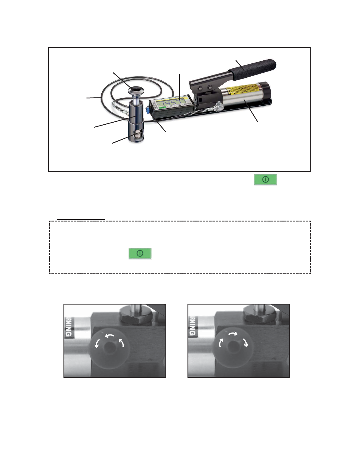
Step 4a: Pull-Off Test
Step 4a: Pull-Off Test
(PosiTest AT-M Manual)
Pump Handle
Actuator Handle
Hose
Actuator
Assembly
Quick Coupling
The PosiTest AT-M powers-up and displays dashes when the button is
pressed. To preserve battery life, the instrument powers down after 5 minutes of
no activity.
LCD
Pump
USB Data Transfer /
Power Port
Quick Guide
(1) Open the pressure relief valve completely (turn counter clockwise)
(2) Connect the actuator to the dolly
(3) Close the pressure relief valve completely (turn clockwise)
(4) Zero - Press the Zero button.
(5) Pump pressure into the system until the dolly pulls the coating away
1. Ensure the pressure relief valve on the pump is completely open. (turn
counter clockwise)
OPEN
CLOSE
2. Push the actuator handle completely down into the actuator assembly. Place
the actuator assembly over the dolly head and attach the quick coupling to the
dolly by reaching through the holes in the actuator assembly and lifting the quick
coupling. Release the quick coupling when the dolly head is completely engaged.
Page 6
Find Quality Products Online at: sales@GlobalTestSupply.com
www.GlobalTestSupply.com
Page 6

3. Close the pressure relief valve on the pump completely. (turn clockwise)
NOTE:
button. Select the pressure units by pressing the button. The
instrument will maintain these adjustments even after the button is
pressed.
As required, verify and adjust the dolly size by pressing the
4. Zero the instrument BEFORE pumping by pressing the button. This
prepares the instrument for the test by clearing the display, and zeroing the
instrument.
5. Prime the pump slowly until the displayed reading approaches the priming
pressure. The priming pressure is the point that the instrument begins calculating
and displaying the pull rate. It is also the pressure at which the ability to store
readings is enabled. Priming pressures for the various dolly diameters are:
10 mm 400 psi 2.8 MPa
14 mm 200 psi 1.4 MPa
20 mm 100 psi 0.7 MPa
50 mm 50 psi 0.4 MPa
NOTE:
pump handle to its full upright position and then complete a single stroke at the
desired pull rate until the actuator separates the dolly from the coating.
For optimum results, prior to exceeding the priming pressure, return the
6. Open the pressure relief valve and remove the dolly from the actuator
assembly.
7. Readings may be stored into memory by pressing the button (pg. 10).
Troubleshooting (PosiTest AT-M)
Digital display “freezes” at a low value
The Tester uses a sudden drop in actuator pressure as an indication that the dolly
has been pulled from the surface. The test stops and the highest pressure
remains on the display for easy viewing and recording. Pumping up pressure too
quickly at the beginning of a test can cause a sudden pressure pulse, fooling the
Tester into thinking the test is complete. If this happens, restart the test by
opening the pressure relief valve, closing it, then pressing the button. For
more information, see Step 5 above.
Page 7
Find Quality Products Online at: sales@GlobalTestSupply.com
www.GlobalTestSupply.com
Page 7
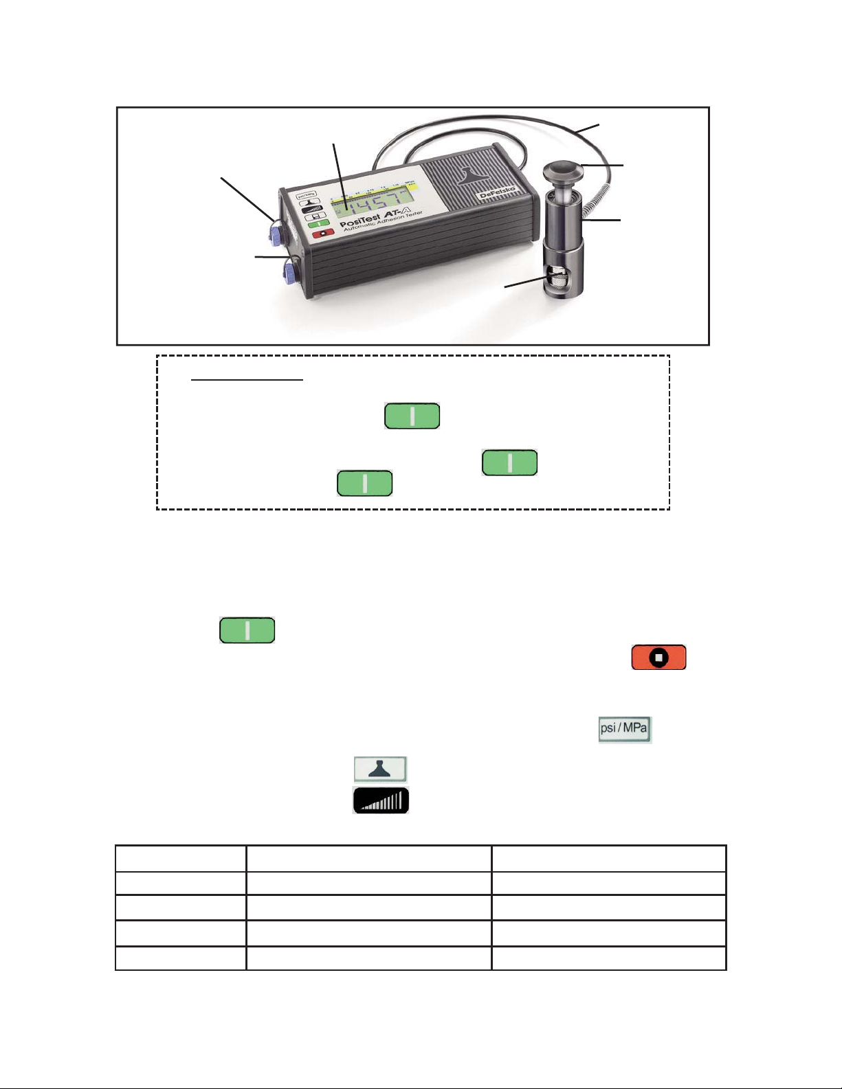
Step 4b: Pull-Off Test
Step 4b: Pull-Off Test
(PosiTest AT-A Automatic)
Hose
Actuator
Handle
Actuator
Assembly
USB port
AC Adapter Port
(Charges batteries
and powers instrument)
LCD
Quick
Coupling
Quick Guide
(1) Connect the actuator to the dolly
(2) Power-up with the button
(3) Verify measurement units, dolly size and pull rate
(4) Ready the instrument with the button
(5) Test with the button
1. Place the actuator assembly over the dolly head and attach the quick coupling
to the dolly by reaching through the holes in the actuator assembly and lifting the
quick coupling. Release the quick coupling when the dolly head is completely
engaged.
2. Press the button to power-up the instrument if necessary. The instru-
ment will power-down after 5 minutes of no activity or by holding the button for 2 seconds.
3. Check settings:
(a) Verify displayed measurement units. Change with the button if
necessary.
(b) Verify dolly size with the button and change if necessary.
(c) Verify pull rate with the button and change if necessary. The
following user selectable rates are available:
Dolly Size PSI Rates MPa Rates
10 mm 125, 200, 400, 600, 725 1.00, 2.00, 3.00, 4.00, 5.00
14 mm 60, 100, 200, 300, 360 0.40, 0.70, 1.40, 2.00, 2.50
20 mm 30, 50, 100, 150, 180 0.20, 0.30, 0.70, 1.00, 1.20
50 mm 5, 8, 16, 24, 30 0.04, 0.08, 0.12, 0.16, 0.20
Page 8
Find Quality Products Online at: sales@GlobalTestSupply.com
www.GlobalTestSupply.com
Page 8

4. Press the button to ready the instrument. This prepares the PosiTest
for the test by clearing the display and zeroing the instrument.
5. Press the button again to start the test that consists of 4 stages
that occur automatically:
Stage 1. Initiation - the display shows a blinking "0".
Stage 2. Priming - the pump applies initial pressure to the dolly.
Stage 3. Test - when the priming pressure has been achieved (see step 5 on pg.
7) the instrument begins calculating and displaying the pull rate established by the
user. Pressure build-up stops when the dolly is pulled from the surface or when
the button is pressed.
Stage 4. Retraction - the maximum pull-off pressure value blinks on the display
while the pump retracts the actuator. The buttons are locked during this stage.
CAUTION: To avoid injury, keep fingers away from the quick coupling
and actuator assembly until the pull test has completed and the actuator
has been fully retracted. Press to stop the pull test at any time.
6. Remove the dolly from the actuator assembly.
7. Readings may be stored into memory by pressing the button (pg. 10).
All settings and test results in memory are retained during power-down.
The red button may be pressed to stop the pull test at any time. The
maximum pressure value will remain on the display while the pump retracts the
actuator. This value can be stored into memory and will be uniquely identified by
the optional PosiSoft software. Stopping the pull test before destruction is handy
when specifications allow the test to be stopped when required adhesion
strengths have been exceeded. Uncouple the actuator from the dolly and then
remove the dolly from the surface with a sharp, sideways hammer tap.
Troubleshooting (PosiTest AT-A)
Instrument is unresponsive or will not power down
In the unlikely event that the PosiTest becomes unresponsive or will not
power down, press and hold the button, then press the
button. The instrument will power down.
Page 9
Find Quality Products Online at: sales@GlobalTestSupply.com
www.GlobalTestSupply.com
Page 9

Step 5: Analysis of Test Results
Step 5: Analysis of Test Results
Test results can be considered 100% valid when the coating is completely
removed from the substrate. When only a portion of the coating is removed, specific results should be noted including the fracture pattern to determine the cohesive properties of the coating and adhesion properties between the dolly and
adhesive, adhesive and coating, distinct coating layers, and coating and substrate.
Step 6: Storing Pull-Off values into Memory
Step 6: Storing Pull-Off values into Memory
The PosiTest’s internal memory stores maximum pull pressure, pull rate,
test duration and dolly size for up to 200 pulls.
Press the button upon completion of a test to store pull-off test
results. The display will show the pull rate and alternate between the test
number and the maximum pull pressure for that test. The con will
appear to indicate that there are test results in memory.
Press the button repeatedly to view previously stored test results.
The PosiTest AT-A also displays dolly size and pull rate by
pressing their respective buttons.
Complete information on all test results can be downloaded to a PC and
viewed using the optional PosiSoft software. Test results are not erased
from memory after downloading. Press (AT-M manual) or
(AT-A automatic) to exit viewing mode.
To remove all stored test results from memory, press and hold the
or button, then press the button. The icon will
disappear from the display.
All settings and test results in memory are retained during power-down.
Available Options
Available Options
A variety of accessories are available to help you get the most out of your
PosiTest Pull-Off Adhesion Tester.
Page 10
Find Quality Products Online at: sales@GlobalTestSupply.com
www.GlobalTestSupply.com
Page 10

Power Supply / Low Battery Indicator
Power Supply / Low Battery Indicator
PosiTest AT-M (manual)
Power Source: Built-in rechargeable NiMH battery (~60 hours continuous)
The built-in rechargeable NiMH batteries** are charged using the included USB
AC power supply/charger. Ensure batteries are charged prior to use. The
symbol will blink while the instrument is recharging and disappear when fully
charged. The charging process will take up to 14 hours depending on remaining
battery power.
Alternatively, the AC power supply or any computer USB port can be used to
power and charge the instrument.
PosiTest AT-A (automatic)
Power Source: Built-in rechargeable NiMH battery (>200 pulls with full charge)
The symbol will appear when remaining battery power is below 35%.
The built-in rechargeable NiMH batteries** are charged using the included AC
power supply/charger . Ensure batteries are charged prior to use. The symbol
will blink while the instrument is recharging and disappear when fully charged.
The charging process will take 2-3 hours depending on remaining battery power .
Alternatively, the AC power supply can be used to power the instrument.
NOTE:
connection will drain battery power when connected for an extended period of
time.
**Do not attempt to remove or replace the internal NiMH battery pack. In the
unlikely event power issues are experienced, please contact our technical
support for assistance.
The USB port will not charge or power the PosiTest AT-A. The USB
Technical Data
Technical Data
Conforms to: ASTM D 4541, ASTM D 7234, ISO 4624 and others.
Specifications:
Resolution: 1 psi (0.01 MPa) Accuracy: ±1% Full Scale
Dolly Size (mm) Max Pull-Off Pressure
10 mm
10,000 psi (70 MPa)
Adhesion
Strength
14 mm
20 mm
6,000 psi (40 MPa)
3,000 psi (20 MPa)
50 mm*
500 psi (3.5 MPa)
*requires optional 50 mm accessory kit
Page 11
Find Quality Products Online at: sales@GlobalTestSupply.com
www.GlobalTestSupply.com
Page 11

Calibration
Calibration
The PosiTest is
national standard. For organizations with re-certification requirements, the
PosiTest may be returned at regular intervals for calibration. DeFelsko
recommends that our customers establish the instrument calibration intervals
based upon their own experience and work environment. Based on our product
knowledge, data and customer feedback, a one year calibration interval from
either the date of calibration, date of purchase, or date of receipt is a typical
starting point.
There are no user serviceable components. Any service must be performed by
DeFelsko Corporation.
If you need to return the Instrument for service, describe the problem fully and
include reading results, if any. Be sure to include contact information including
your company name, company contact, telephone number and fax number or
email address.
shipped with a Certificate of Calibration showing traceability to a
Returning for Service
Returning for Service
Limited W
Limited W
DeFelsko’s sole warranty, remedy, and liability are the express limited warranty,
remedy, and limited liability that are set forth on its website:
This manual is copyrighted with all rights reserved and may not be reproduced or transmitted, in whole or part, by any means, without written permission from DeFelsko Corporation.
DeFelsko, PosiTector, PosiTest and PosiSoft are trademarks of DeFelsko Corporation registered in the U.S. and in other countries. Other brand or product names are trademarks or
registered trademarks of their respective holders.
arranty
arranty
© DeFelsko Corporation USA 2011. All Rights Reserved
, Sole Remedy and
, Sole Remedy and
Limited Liability
Limited Liability
Protection provided by the equipment may be impaired if the equipment is used in a manner
not specified by the manufacturer.
Every effort has been made to ensure that the information in this manual is accurate.
DeFelsko is not responsible for printing or clerical errors.
Find Quality Products Online at: sales@GlobalTestSupply.com
www.GlobalTestSupply.com
Page 12

Simple. Durable. Accurate.
© DeFelsko Corporation USA 2011
All Rights Reserved
manual is copyrighted with all rights reserved and may not be reproduced or
This
transmitted, in whole or part, by any means, without written permission from DeFelsko
Corporation.
DeFelsko, PosiTector and PosiSoft are trademarks of DeFelsko Corporation registered in
the U.S. and in other countries. Other brand or product names are trademarks or
registered trademarks of their respective holders.
Every effort has been made to ensure that the information in this manual is accurate.
DeFelsko is not responsible for printing or clerical errors.
Find Quality Products Online at: sales@GlobalTestSupply.com
www.GlobalTestSupply.com
 Loading...