

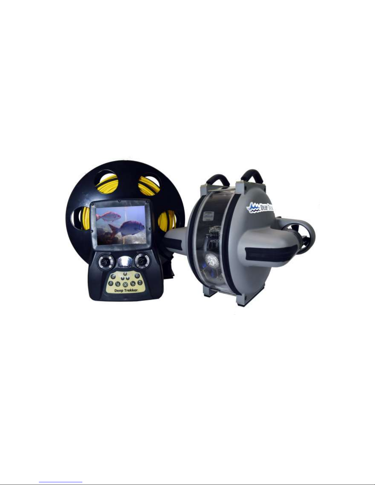
Deep Trekker DTG2 User Manual
Version 2.0 2016
06-9915-01-01 to 06-9915-01-100
06-9916-01-01 to 06-9915-01-200

DEEP TREKKER DTG2 USER MANUAL
DEEP TREKKER INC.
2
Warning
Never operate your DTG2 in the presence of unaware swimmers or divers.
Always use a Personal Flotation Device (PFD) and obey any laws pertaining to the operation of your
launch vehicle.
NOTE: Because of the sharp running hardware included with this product, we do not recommend a
rubber blow up raft.
Extreme caution should be taken if piloting the DTG2 ROV in swimming pools, as the sharp edges
could damage the pool liner.
The DTG2 running hardware is very sharp. Be very careful when working on and around the parts.
While the motor is running pay close attention to the propeller. Do not come in contact, or put
fingers near the propeller at any time the system is turned on or serious injury will result.
The speed and mass of this DTG2 ROV can inflict property damage and severe personal injury if a
collision occurs. Never run this ROV in the presence of unaware swimmers or boaters or where the
possibility of collision with people or property exists.
The density of each body of water is different, before operation in a new body of water, adjusting
the weight of the ROV is necessary to avoid damage to the ROV or property around it. Each DTG2
ROV is equipped with ballast weights to place under the handles or on the bottom of the ROV.
Deep Trekker products are to be used by people 16 years of age and over.
Always read the owner’s manual before operation.

DEEP TREKKER DTG2 USER MANUAL
DEEP TREKKER INC.
3
Contents
Warning........................................................................................................................................................................................................ 2
Safety Precautions ....................................................................................................................................................................................... 4
Manual Specification and Description Changes ........................................................................................................................................... 5
Delivery and Inspection ................................................................................................................................................................................ 6
System Overview .......................................................................................................................................................................................... 7
Calibrating the Buoyancy ........................................................................................................................................................................... 11
Launching your First Dive ........................................................................................................................................................................... 12
Operation ................................................................................................................................................................................................... 13
On / Off ........................................................................................................................................................................................... 13
Driving Controls .............................................................................................................................................................................. 13
Thruster Trim .................................................................................................................................................................................. 14
Pitch Trim ........................................................................................................................................................................................ 14
Gain /Scroll Buttons ........................................................................................................................................................................ 14
Primary Flood Lights........................................................................................................................................................................ 15
Auxiliary Flood Lights (Optional Equipment) ................................................................................................................................... 15
Camera Up/Down Buttons .............................................................................................................................................................. 15
Forward Camera ............................................................................................................................................................................. 15
Camera Lock .................................................................................................................................................................................... 15
Pitch Lock ........................................................................................................................................................................................ 16
Reset ............................................................................................................................................................................................... 16
Grabber Open/Close Buttons (Optional Equipment) ...................................................................................................................... 16
Grabber Rotate Buttons (Optional Equipment) .............................................................................................................................. 16
LED Indicators: ................................................................................................................................................................................ 17
Menu Button ................................................................................................................................................................................... 17
Tether: ............................................................................................................................................................................................ 18
Entanglement: ................................................................................................................................................................................. 18
Shutdown ................................................................................................................................................................................................... 19
Charging ..................................................................................................................................................................................................... 19
Storage ....................................................................................................................................................................................................... 21
Transporting ............................................................................................................................................................................................... 22
Optional Equipment - Sensor System ......................................................................................................................................................... 23
Auto-Depth ..................................................................................................................................................................................... 24
Auto-Heading .................................................................................................................................................................................. 24
Turns Counter ................................................................................................................................................................................. 25
On Screen Display On/Off ............................................................................................................................................................... 25
Calibrating the Compass ................................................................................................................................................................. 25
Optional Equipment – Two Function Grabber ........................................................................................................................................... 26
Optional Equipment – Auxiliary Lighting .................................................................................................................................................... 28
Optional Equipment – Laser Scaler ............................................................................................................................................................ 28
Optional Equipment – Crawler Wheels ...................................................................................................................................................... 28
Optional Equipment – Auxiliary Camera(s) ................................................................................................................................................ 29
Optional Equipment – Digital Video Recorder (DVR) ................................................................................................................................. 30
Optional Equipment – Video Glasses ......................................................................................................................................................... 35
Mounting Provisions for Auxiliary Equipment ............................................................................................................................................ 36
Maintenance .............................................................................................................................................................................................. 37
Window Repair........................................................................................................................................................................................... 38
Removing the Tether .................................................................................................................................................................................. 39
Re-Installing the Tether .............................................................................................................................................................................. 40
Trouble Shooting ........................................................................................................................................................................................ 43
Using the Diagnostics Cable ....................................................................................................................................................................... 45
Diagnostics Screens .................................................................................................................................................................................... 46
Parts and Service ........................................................................................................................................................................................ 48
Warranty .................................................................................................................................................................................................... 50

DEEP TREKKER DTG2 USER MANUAL
DEEP TREKKER INC.
4
Safety Precautions
Never attempt to swim after a stalled DTG2. Do not get in the water for any reason to retrieve your
DTG2. Return the DTG2 by gently pulling it back to the boat by the tether. In cases where the
tether is snagged or severed, contact a certified diver to perform the retrieval for you.
Deep Trekker products are to be used by those aged 16 and over.
Do not touch the propeller when the motor is spinning. Pay equally close attention to items such as
loose clothing, shirtsleeves, ties, scarves, long hair or anything that may become entangled in the
spinning propeller. If your fingers, hands, etc. come in contact with the spinning propeller, you may
be severely injured.
Keep your launching and piloting area tidy and your tether neatly rolled to avoid tripping while
operating the DTG2.
The speed and mass of this DTG2 ROV can inflict property damage and severe personal injury if a
collision occurs. Never run this ROV in the presence of unaware swimmers or boaters or where the
possibility of collision with people or property exists.
Be aware of dangers around you, including weather, and obey all applicable laws while using
standard water safety procedures.
The density of each body of water is different, before operation in a new body of water, adjusting
the weight of the ROV is necessary to avoid damage to the ROV or property around it. Each DTG2
ROV is equipped with ballast weights to place under the handles or on the bottom of the ROV.
The DTG2 ROV is equipped with lithium ion batteries, completely enclosed in both the ROV and
controller. Under no circumstances try to open or disassemble the batteries, or expose the batteries
to extreme heat or mechanical shock such as dropping it on a hard surface. If you have not used the
battery pack for a considerable amount of time, the remaining battery life may shorten. The battery
pack will gradually discharge over time even while not in use. We recommend fully charging the
batteries every 6 months to ensure they do not fully self-discharge over time.

DEEP TREKKER DTG2 USER MANUAL
DEEP TREKKER INC.
5
Manual Specification and Description Changes
All pictures, descriptions, and specifications found in this instruction manual are subject to change
without notice. Deep Trekker Inc. maintains no responsibility for inadvertent errors in this manual.
DEEP TREKKER DTG2 USER MANUAL
DEEP TREKKER INC.
6
Delivery and Inspection
Thank you for purchasing the DTG2 inspection and exploration system; the world’s only premium grade,
portable, affordable and easy to use underwater ROV. We want the time you spend with your new
remotely operated vehicle (ROV) to be entertaining and successful so please read the entire manual
before using this product for the first time.
The DTG2 ROV is ready for use as delivered from the factory. The unit has been fully tested and
inspected prior to shipping, including a pressure test equivalent to the maximum dive depth.
Leaving the batteries fully drained for long periods of time will cause permanent damage. We
recommend fully charging them every 6 months to ensure they do not fully self-discharge over time.
For more information regarding the charging, see the section in the manual entitled Charging.
Fully inspect your ROV to ensure it has not been damaged during shipping. If you suspect a problem
please contact Deep Trekker support or your authorized Deep Trekker Dealer for assistance.
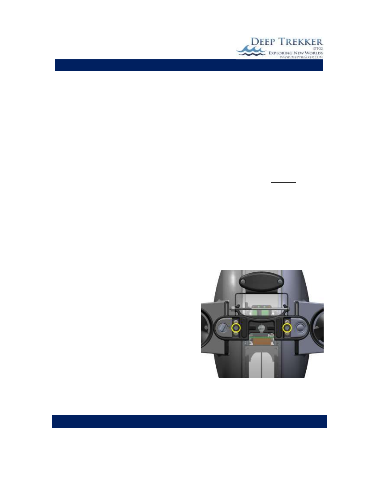
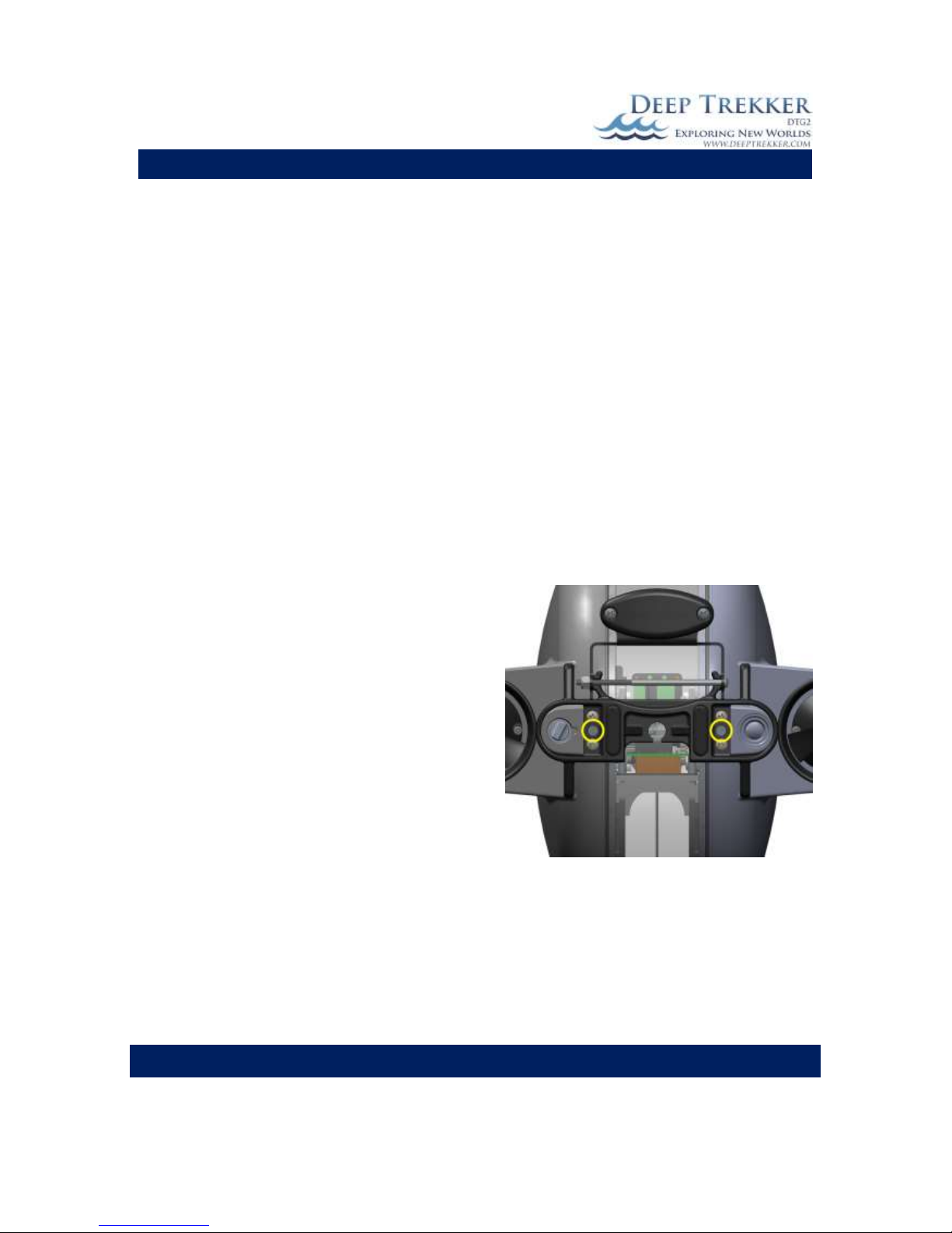
The DTG2 is shipped to you with the two shipping set screws in the locked position, the DTG2 will not
operate with these screws locked. This ensures that the rough motions associated with the delivery
service do not damage the internal frame and the servo motor that turns it.
To release the shipping set screws the following steps
must be taken.
1) Rotate ROV upside down with the handles facing
downward. This will ensure it does not rotate
until the screw is completely backed out. While in
this position, turn both set screws using a flathead
screwdriver counter-clockwise until the set screw
heads are firmly against the cover plate.
*DO NOT COMPLETELY REMOVE THE SHIPPING SET
SCREW UNDER ANY CIRCUMSTANCES. THIS OPENS
UP THE SEALED UNIT AND WILL LEAD TO IMMEDIATE
FAILURE IF SUBMERGED*
2) Slowly rotate ROV to its level position.
Fig 1

DEEP TREKKER DTG2 USER MANUAL
DEEP TREKKER INC.
7
System Overview
The DTG2 ROV is designed to operate in fresh or salt water between the temperatures of -5C [23F] to
45C [113F]. This unique ROV incorporates internal/onboard batteries, so the system is completely
portable with no top side generator or box required. The tether is also much smaller and lighter than a
tether designed to carry power. The controller replicates a traditional game pad, reducing the learning
curve of successfully operating the DTG2 significantly.
The use of magnetic couplers means that there is no dynamic shaft seal on board the DTG2. This feature
dramatically increases reliability and requires no maintenance, greasing or replacing any seals on the
ROV.
The patented pitch control aims the outer shell (thrusters) to any angle +/- 90 degree from center for a
total of 180 degrees. This system that works entirely from within the hull, eliminates the requirement of
a third or fourth thruster and further increases reliability and ease of use.
The ROV and tether are 100% waterproof and should not take on water unless damaged. The standard
controller is splash resistant, but should not be submerged or power washed at any time. Other
optional viewing systems offered are not waterproof in any way and need to be used with care of in
outdoor environments. The ROV charger and controller charger are indoor products that should never
be operated near water or wet conditions.
Fig. 2A

DEEP TREKKER DTG2 USER MANUAL
DEEP TREKKER INC.
8
Fig. 2B
DEEP TREKKER DTG2 USER MANUAL
DEEP TREKKER INC.
9
Fig. 3A

DEEP TREKKER DTG2 USER MANUAL
DEEP TREKKER INC.
10
Fig. 3B

DEEP TREKKER DTG2 USER MANUAL
DEEP TREKKER INC.
11
Calibrating the Buoyancy
The DTG2 ROV is shipped from the factory calibrated for fresh water use. To adapt for salt water, simply
add the provided ballast plates, as shown in Fig. 4, evenly to the top mounting points or bottom
mounting points. These weights can be added or removed as desired to gain the preferred buoyancy. It
is most common to bias the buoyancy to a neutral or slightly positive setting.
Every body of water will have a different density, generally when changing to salt water, we recommend
adding 4 ballast plates to start. From there, small ballast plates can be added or removed to ensure
neutral buoyancy.
Fig. 4

DEEP TREKKER DTG2 USER MANUAL
DEEP TREKKER INC.
12
Launching your First Dive
Prior to operating the DTG2 system, ensure you have read the entire operator’s manual and fully
understand it. Once fully charged, remove the charger from the ROV and set it right side up on a secure
surface. This is important because as soon as the system is active the pitch system will rotate to this
level condition.
Turn the controller on with the ON/OFF button. The controller and ROV will enter the boot sequence
that should last no longer than 5 seconds. The video camera will come out of its upward park position
and point forward. The camera and light are now safe to use. The pitch system should not be activated
until the DTG2 is in the water, as it could cause the DTG2 to fall over unexpectantly.
Every dive should include a short inspection to ensure that everything is in order:
1) Check the thrusters for any debris that may be left from the prior dive.
2) Inspect the tether to ensure that it has not been worn or breached in any way.
3) Check for loose fasteners on the ROV.
4) Check the connection between the window and side bodies to ensure they are sealed.
5) Turn on the system and check functionality of the thrusters, lights and camera. Do not operate
the pitch system while out of water. The lights can run indefinitely while the ROV is out of water.
Once the inspection is complete prepare to launch using the following steps as a minimum:
1) Inform anyone nearby such as divers, swimmers, or boaters that you are deploying the DTG2
and its tether. Only deploy if you have their approval.
2) Ensure your launch and piloting areas are clean.
3) Ensure your tether is neat and ready to deploy.
For a first trial run, choose a safe shallow and clear body of water that does not include obstacles
capable of tangling the tether. There should be no wind or current present.
Lower the DTG2 into the water by the handles, or gently lower it in by the tether. Do not throw the
DTG2 into the water for risk of striking an object.
At this point it is advised to operate the ROV without relying on the camera and viewing system. Keep it
near the surface for easy visibility and familiarize yourself with the controls.
Once you are familiar with the controls of the ROV, you may begin to use solely the viewing screen to
maneuver the DTG2. We recommend keeping infrastructure or a stagnant object in view to keep your
orientation when learning.

DEEP TREKKER DTG2 USER MANUAL
DEEP TREKKER INC.
13
Operation
On / Off
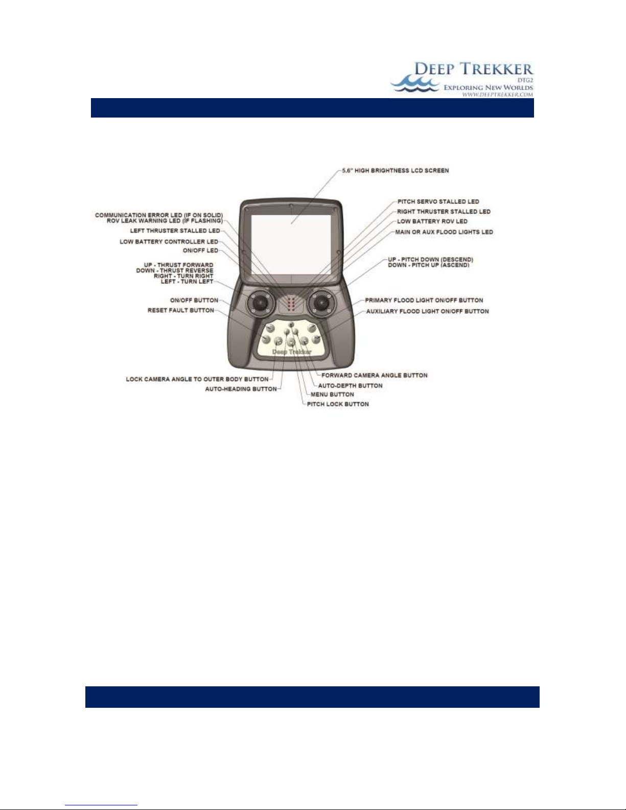
The ON/OFF button as shown in Fig. 3A acts as an ON button when the ROV is
off, and an OFF button when the ROV is on. Pressing the on button starts a
boot sequence that will last about 4 seconds.
If the ROV is turned off while diving, simply turn it back on. It does not have
to be on dry land for a re-boot.
If the controls have not been activated on the controller for several minutes
the system will automatically shut down. This will shut down the controller
and ROV. If you are also using optional viewing systems such as the video
glasses or digital video recorder – these will not shut down automatically.
Driving Controls
As shown in Fig. 5, the motion of the DTG2 is accomplished with
only 2 joysticks. The left joystick completely controls the thruster
in an intuitive manner. Driving the DTG2 on a lateral plane.
Forward on the joystick is forward on the ROV. Back on the
joystick is reverse on the ROV. Right and left on the joystick are
turning the ROV right and left.
The patented pitch system rotates the entire outer body up and
down. This feature transforms the thrust motion from the
primary thrusters into vertical motion. Like an airplane, if you
point the jets up, it will climb, if you point them down it will
descend. The DTG2 is essentially the same thing in water, except
because it is the same weight as water (if you the operator
calibrated it correctly) it will remain at the same depth until the
thrusters move it up or down. Rotating the pitch system is
accomplished with the right joystick. Point the right joystick
forward to face the ROV downward. Pull the right joystick back
to point the ROV upward.
Drive Up
Drive Down
Fig. 5

DEEP TREKKER DTG2 USER MANUAL
DEEP TREKKER INC.
14
Thruster Trim
The right and left thrusters can be trimmed to ensure the ROV drives straight when the
joystick is full forward. Small variances in the ROV can pull it slowly to one side. To adjust
the thruster trim, place the ROV in an open body of water with no wave action or current.
Descend the ROV slightly below the water line so it is fully submerged but still visible by eye.
Throttle the thrusters full forward and observe the path it takes. Do not attempt to trim the
thrusters with the auto-heading or auto-depth engaged. (See Page 24 for more information
on auto-heading and auto-depth)
To calibrate the Thruster Trim: Press the MENU button, scroll down with the right joystick to
‘CALIBRATE’. Press the ‘2’ button to enter this menu. Use the right joystick to scroll down to
Trim Right or Trim Left. Press ‘2’ to trim the thruster 1% each time you select an option.
Pitch Trim
The pitch can be trimmed to hold any angle without using the pitch joystick. This allows an
operator to fine tune the “home” position of the tilt of the ROV to slightly up, perfectly
horizontal, or slightly down, depending on the operator’s preference. Do not attempt to trim
the pitch with the auto-heading or auto-depth engaged. (See Page 24 for more information
on auto-heading and auto-depth)
To calibrate the Pitch Trim: Press the MENU button, scroll down with the right joystick to
‘CALIBRATE’. Press the ‘2’ button to enter this menu. Use the right joystick to scroll down to
Trim Pitch Up or Dn. This will trim the ‘home’ position of the pitch 1 degree each time you
select an option using the ‘2’ button.
Gain /Scroll Buttons
The gain control can be adjusted on the hand controller to increase or decrease the speed of
the ROV. For example, in situations where there is no current and small precise movements
are necessary, reducing the gain may be beneficial. The Gain up/down buttons are located at
the front inner right hand side of the controller. The up button increases the ROV gain and
the down button decreases the ROV gain. When the gain buttons are used, your speed will
appear in the top center of the screen for 5 seconds. Once it disappears the gain has been
set. By default the ROV gain starts at 8 but can be increased up to 10 or decreased to 4. Gain
is the overall power sent to the thrusters, so an 8 is 80%, 5 is 50% and so on.
These arrows also function as scrolling buttons that activate immediately after various
other buttons are pressed. The user has 5 seconds to make adjustments to these settings
before the arrows return to gain adjust. There is always a scrolling number shown on
screen to allow the user proper feedback.
These gain control up/down button will also adjust these functions when they are first
activated.
1. Auxiliary Flood Light – use to scroll the intensity of the light. (0-100%)
2. Auto-Heading – Use to scroll to target heading (0-360 degrees)
3. Auto-Depth – Use to scroll to target depth (0-152 m [0-500 ft]

DEEP TREKKER DTG2 USER MANUAL
DEEP TREKKER INC.
15
Primary Flood Lights
The primary flood light button, shown in Fig. 3A, turns the primary flood lights on and off.
The primary floodlights are located inside the ROV mounted below the camera.
Auxiliary Flood Lights (Optional Equipment)
The auxiliary flood light button shown in Fig. 3A, turns the two auxiliary flood lights on and
off. The two auxiliary floodlights are located fixed to the shell at the front of the ROV.
Immediately after the auxiliary flood lights are turned on, an intensity level value defaulting
at 100% appears in the upper portion of the LCD screen. Use the gain arrows up and down
to adjust the level of light intensity. Once the arrow buttons are left unadjusted for more
then a few seconds the intensity value will disapear from the screen and the arrows will
return to the gain adjust.
Camera Up/Down Buttons
The camera up/down buttons are located at the front outer right hand side of the
controller. The up button rotates the camera up and the down button rotates the camera
down.
Forward Camera
The camera can quickly be aligned with the pitch angle, or in other words the forward
direction the ROV is headed, by pressing the Forward Camera button. This is helpful when
you want to look in the direction of motion without using the camera up/down arrows to
manually align it.
Camera Lock
The camera can be locked to the pitch angle by pressing the Camera Lock button. This
means that if the pitch angle changes by + 45 degrees, the camera angle will also change by
+45 degrees, ensuring that the camera is generally looking in the direction of travel at all
times. When the Camera Lock is first activated, the camera angle will be equal to the pitch
angle, however if you would like to offset the angle slightly, you can use the camera up and
down arrows. These are most useful when using the grabber and a fixed view of the
grabber claw is required.
DEEP TREKKER DTG2 USER MANUAL
DEEP TREKKER INC.
16
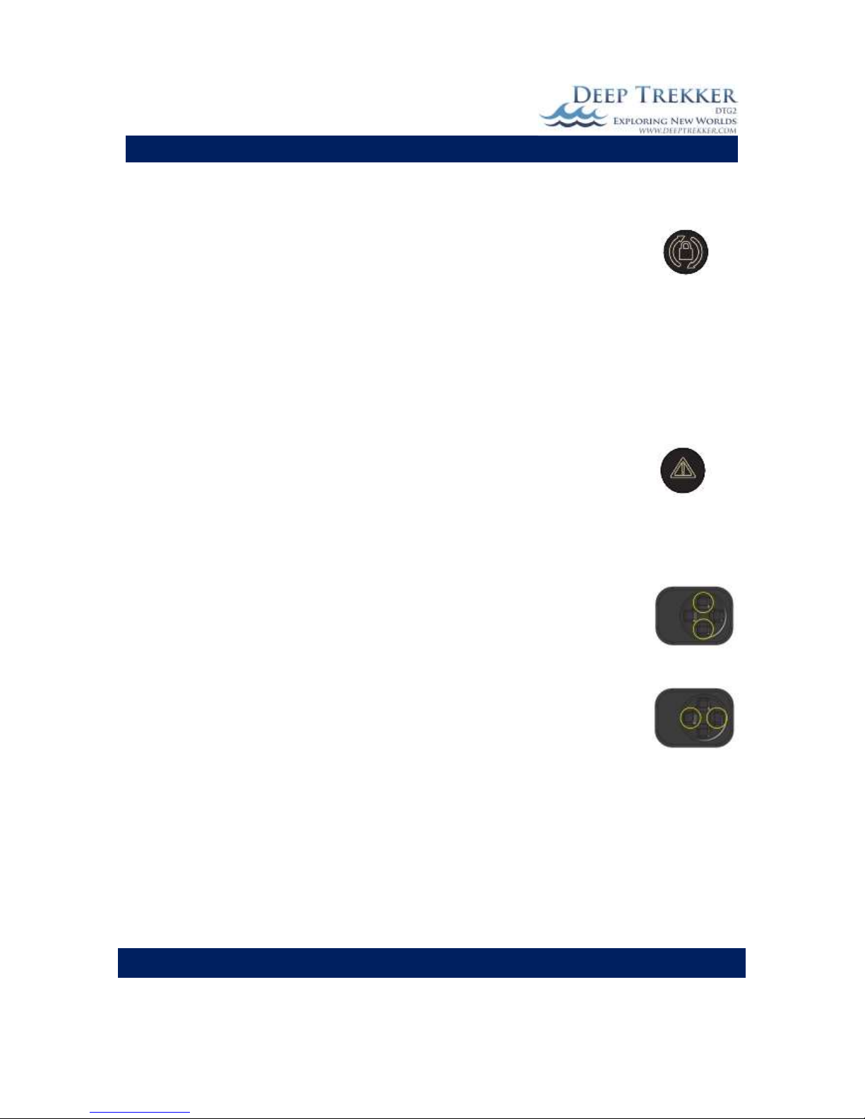
Pitch Lock
By default, when the unit is turned on, the pitch angle of the ROV follows the present
position of the pitch joystick (the right joystick). Since the joystick is “spring return to
center”, the body will also return to a 0 degree (horizontal) pitch when the operator’s
thumb is off the joystick. If the pitch lock button is pressed, the operation of the pitch
joystick scrolls the pitch angle up or down and when the joystick is released, the pitch
angle remains at the last selected angle. When the pitch lock mode is on, a target pitch
angle value is shown on the screen within (parentheses). This function is useful when
following a mooring line up or down on a constant angle. To release the pitch lock
back to center mode, simply press the pitch lock button again.
Reset
The Reset button is used to reset the thruster system or pitch system after a fault.
When the thrusters or pitch motor draw too much current, the ROV computer detects
this and shuts the system down in order to protect it. The most common cause of this
occurrence would be when the propeller is fowled. The system is re-activated after the
problem has been corrected by either pressing the reset button, or turning off/on the
entire ROV.
Grabber Open/Close Buttons (Optional Equipment)
The grabber open/close buttons are located at the front outer left hand side of the
controller. The up button opens the grabber claws and the down button closes the
grabber claws.
Grabber Rotate Buttons (Optional Equipment)
The grabber rotate buttons are located at the front inner left hand side of the
controller. The up button rotates the grabber claws Clockwise and the down button
rotates the grabber claws Counter Clockwise.

DEEP TREKKER DTG2 USER MANUAL
DEEP TREKKER INC.
17
LED Indicators
Check the controller’s LED indicators often.
When the ROV battery LED it flashing, the ROV will slow down considerably. Return it to the boat and
charge it when safely indoors.
When the low controller battery LED is flashing, you are very low on controller power and need to finish
the dive. If the controller battery is critically low, it will stop sending data to the ROV, rendering the
system unusable. Once the system is safely back indoors plug the controller charger into the controller
charge port as shown in Fig. 3B.
If the RH & LH thruster error LED light is on, return the ROV to the boat and turn the system off. Inspect
the propellers and magnetic coupler for binding objects. Removal of the guards and propeller may be
required. Once the debris is removed, turn on the system again and test the thrusters in and out of the
water. If the thruster error LED turns on again, contact Deep Trekker support or your authorized Deep
Trekker Dealer for assistance.
If the pitch stall LED turns on, simply press the reset thrusters/pitch button on the controller. The pitch
can be stalled by excessive pull on the tether or by trying to pitch the system out of the water. If the
pitch stall LED turns on again contact Deep Trekker support or your authorized Deep Trekker Dealer for
assistance.
The no communication & leak LED will turn on if: 1) the ROV is extremely low on batteries, 2) the tether
is unplugged or damaged or; 3) when the ROV is being charged. If a full battery charge does not fix the
problem, contact Deep Trekker support or your authorized Deep Trekker Dealer for assistance. See also
the trouble shooting guide portion of the manual. The second function of the no communication LED is
to warn of water intake into the ROV hull. The communication LED will flash quickly if water is sensed.
During this occurrence the ROV will become immobile and you must pull it out of the water as quickly as
possible and contact Deep Trekker support or your authorized Deep Trekker Dealer for assistance.
Menu Button
The Menu button allows access to the system settings, calibration and diagnostics tools.
Once the menus have been activated, scroll up or down with the right hand joystick and
make selections using the right hand joystick button.
DIAGNOSTICS
POWER shows system battery levels, current levels (see Diagnostics Section for detail)
COMMUNICATIONS shows system communication status (see Diagnostics Section for detail)
BUTTONS shows the buttons status on the controller (see Diagnostics Section for detail)
CONTROLLER shows the joysticks& misc. status on the controller (see Diagnostics Section for detail)
ROV shows the ROV status on the controller (see Diagnostics Section for detail)
EXIT

DEEP TREKKER DTG2 USER MANUAL
DEEP TREKKER INC.
18
CALIBRATE
TRIM PITCH UP Trim the home position of the pitch up 1 degree per press (see Pitch Trim for detail)
TRIM PITCH DN Trim the home position of the pitch down 1 degree per press (see Pitch Trim for detail))
TRIM RIGHT Trim the thrusters right - 1% per press (see Thruster Trim for detail)
TRIM LEFT Trim the thrusters left - 1% per press (see Thruster Trim for detail)
DEPTH 0M Set the 0m depth (on land) setting. Required for atmosphere and temperature changes
FACTORY D –ROV Return all calibration settings to factory default settings
EXIT
SETUP
UNITS: Select the units of measure (Imperial or metric)
LANGUAGE: Select the language
OSD: Turn on or off the On-Screen-Display (OSD)
EXIT
EXIT
Tether:
It is advised to have an assistant managing the tether as the ROV demands more let into the water, or
pulled back out of the water. Leaving too much tether in the water will cause excess drag on the DTG2,
and not having enough will restrict the ROV manoeuvrability. The tether needs to be closely observed
while in use as it poses a threat to swimmers, divers, and boaters.
Do not bend the tether in a radius of 75mm (3”) or less. Do not kink the tether. Never drag the tether
over a rough or sharp surface. This will quickly wear the outer protective jacket and eventually flood the
cable.
Do not step on or drive over the tether. Crushing the tether in any way may damage it in a fashion that
is non-repairable. If your tether does become damaged please contact Deep Trekker support or your
authorized Deep Trekker Dealer for assistance. Under no circumstances is a damaged tether from the
above listed scenarios warrantable.
Entanglement:
Take extreme care in conditions that increase the chance of the tether becoming tangled. If the DTG2
does get tangled, assess the situation with the camera and manoeuvre the ROV appropriately to
become free. Generally, you should be able to find your tether with the camera and follow it back out.
Failing that, the tether can be pulled on lightly with a maximum force of 90 kilograms (200 pounds) to
become free. If that fails it is advisable to find a certified diver who can manually untangle the system.
Never dive in the water yourself to perform this manoeuvre. Under no circumstances is a lost or
damaged system warrantable.
DEEP TREKKER DTG2 USER MANUAL
DEEP TREKKER INC.
19
Shutdown
Once the dive has been completed, you may return the DTG2 to the boat by either using the thrusters or
by gently pulling it back with the tether. Turn the system off and lift it out of the water by the tether
support, or by gently pulling up on the tether. Once safely on shore and set on a sturdy flat surface,
inspect the outer body for foreign objects and remove as necessary. Inspect the interior through the
window for any sign of water and the inner window for fogging. If you see either of these problems you
may have a breach in the hull and need to contact Deep Trekker support or your authorized Deep
Trekker Dealer for assistance.
Wipe down the ROV with a towel or rag. If the DTG2 has been used in salt water it is advised to rinse it
with fresh water to ensure it does not corrode. After the fresh water rinsing, wipe the ROV dry. If the
optional carry case is used, do not close the lid after use. Allow 1-2 hours for the ROV and tether to dry
off 100% prior to sealing the case shut. Any significant amount of moisture left in the case will promote
corrosion. If the DTG2 has been launched from a boat, stow it safely before moving on. Do not let the
ROV bounce around the boat.
Charging
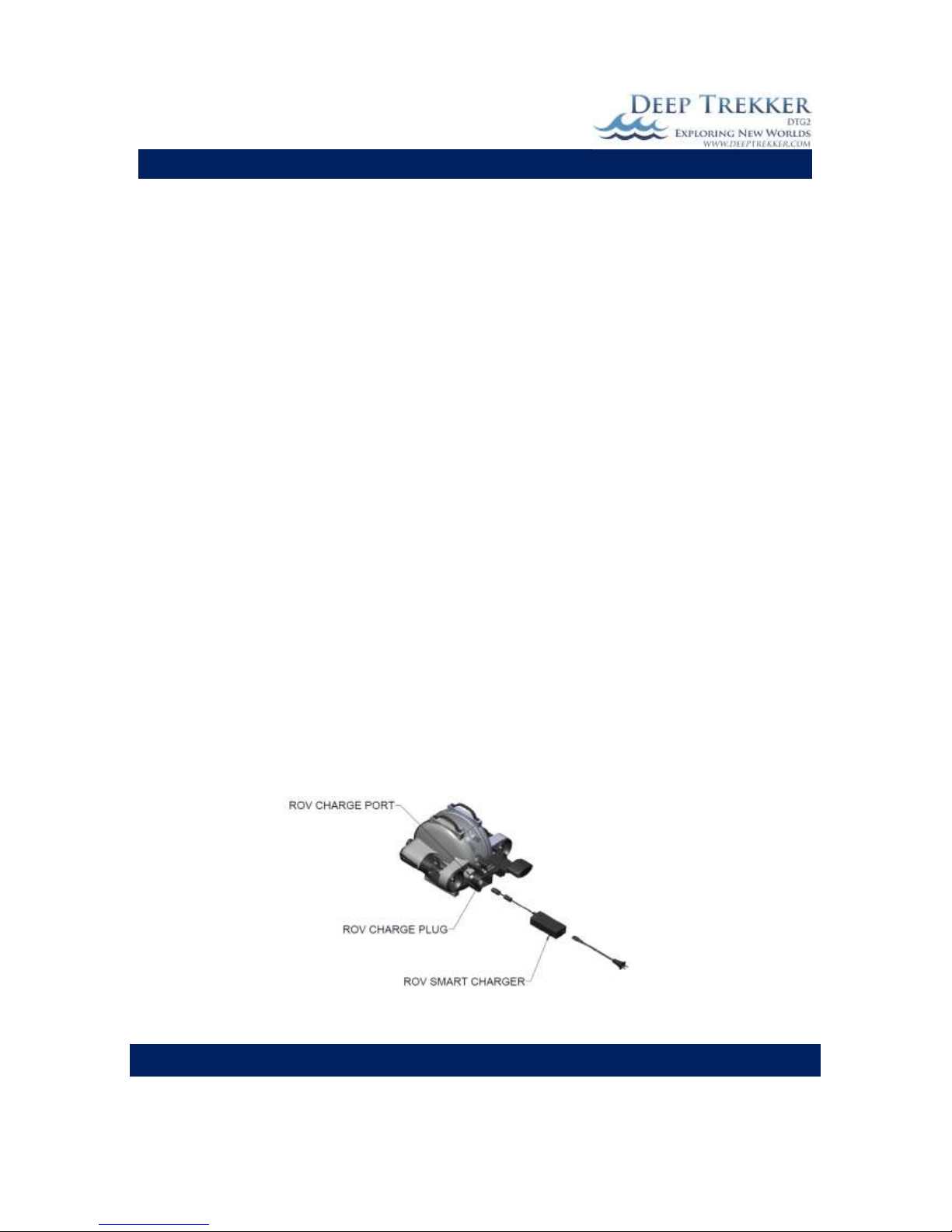
Charging the DTG2 ROV must be done when the unit is safely indoors in a dry environment. Never put
the DTG2 ROV in the water or near water when it is being charged. The length of time it takes to charge
depends on the condition of the battery packs. It should not take longer than 2.5 hours to charge after
5 to 8 hours of use. Remove the charge port plug, ensure port is dry and insert the charger plug into the
ROV. Port pins must be dry prior to charging or damage to the pins will occur. The charger is charging
when the LED on the charger is red. Charging is complete when the green LED appears on the charger.
When the charger is plugged into the ROV, the ROV is unusable, and if the controller is turned on there
will be a no communication fault triggered. Be sure the charge port plug is returned into position before
the next dive. The plug acts as a double seal at this opening and also protects the electrical pins from
corrosion.
Fig. 6
DEEP TREKKER DTG2 USER MANUAL
DEEP TREKKER INC.
20
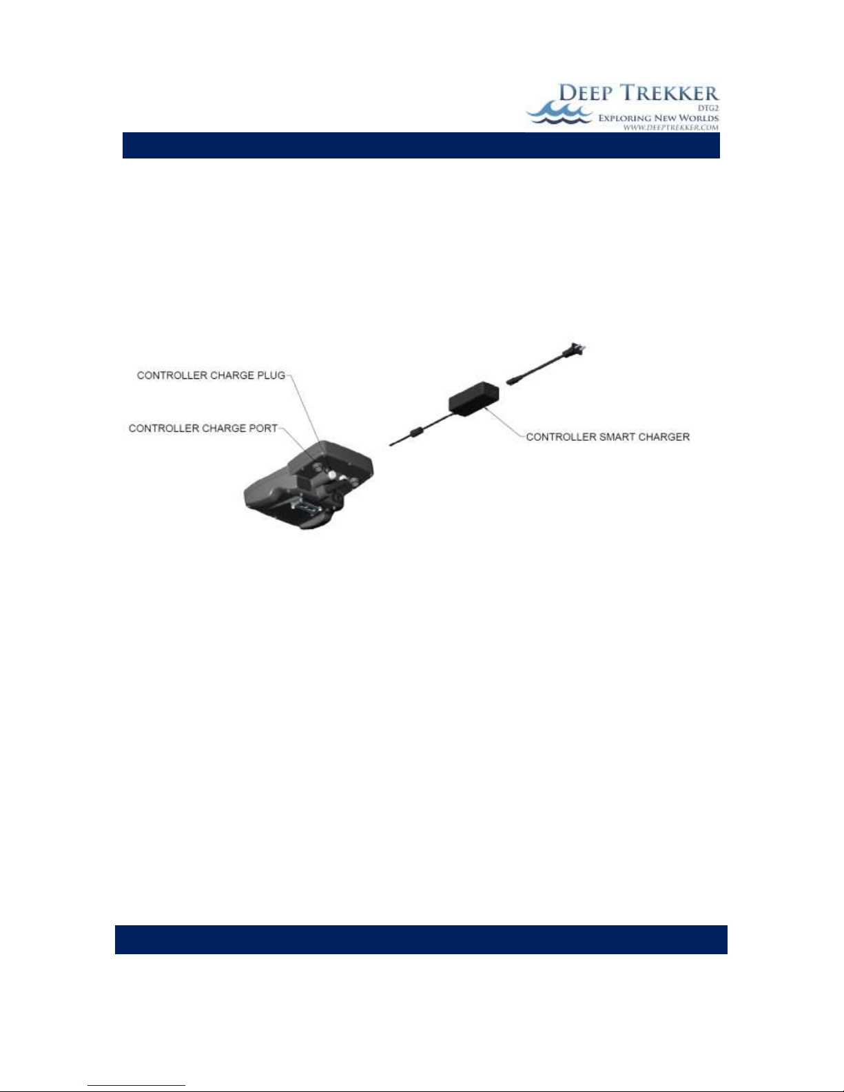
Charging the DTG2 controller must be done when the unit is safely indoors in a dry environment. The
controller is powered by a separate built-in battery pack that will require a charge approximately every 6
hours of run time. When the battery pack is low, the low controller battery LED will turn on. If a charge
is not given within several minutes of the LED warning, the battery will reach a critically low level and
communication with the ROV will stop.
To charge the controller, simply plug the controller charger into the charge port on the controller next to
the tether. Note that the controller charger is different from the ROV charger. The difference in charger
plugs makes them impossible to interchange.
Fig. 7
Note both the ROV and Controller chargers are ‘smart’, meaning there will be no harm in leaving the
chargers plugged in overnight, or giving your DTG2 a quick charge for some extra life on your next dive.
Leaving the batteries fully drained for long periods of time will cause permanent damage. We
recommend fully charging them every 6 months to ensure they do not fully self-discharge over time.

DEEP TREKKER DTG2 USER MANUAL
DEEP TREKKER INC.
21
Storage
Store your ROV in a location that is safe from animals or insects that are capable of causing damage to
the tether. One small hole in the tether will cause it to flood and could lead to a communication failure
between the controller and ROV. Store in dry locations between the temperatures of -20C [-4F] and 40C
[104F] out of direct sunlight. Storing in climates out of this range will lead to premature battery failure.
It is recommended to charge the battery at least once every 6 months if the unit is not being used. If the
ROV is stored in a sealed compartment such as the optional carry case offered by Deep Trekker Inc., the
ROV and tether must be left to dry off 100% prior to sealing the case shut. Any significant amount of
moisture left in the case will promote corrosion.
DEEP TREKKER DTG2 USER MANUAL
DEEP TREKKER INC.
22
Transporting
*It is important to store and transport your DTG2 in a fashion that does not rock the pitch system back
and forth. This will cause premature failure because it is working the gear motor and gear train. This
sort of failure is 100% unwarrantable. An easy way to prevent the pitch system from rocking back and
forth is to stow the ROV upside down such that the internal frame is resting against the mechanical
stops located inside the hull. *
For instances where the DTG2 cannot be safely stored in the upside down position, such as during
courier shipping (UPS/FedEx/DHL etc.), the use of the 2 shipping set screws may be required. These
screws are found on the rear of the ROV behind the tether bracket. Their purpose is to mechanically
hold the internal framework so that it is unable to move. To properly use the set screws, the following
steps must be taken:
1) Slowly rotate ROV backwards (as if to ascend) to position the internal frame against the stops.
2) While in this position, turn the set screws using a flathead screwdriver clockwise until they are
firmly against the internal frame and holding it in this position.
In this configuration the ROV is unusable and should not be turned on. If the ROV is mistakenly turned
on, the pitch stall error LED will appear because the servo motor cannot override this mechanical
connection.
To release the shipping set screw the following steps
must be taken.
1) Rotate ROV upside down with the handles
facing downward. This will ensure it does not
rotate until the screw is completely backed
out. While in this position, turn both set
screws using a flathead screwdriver counterclockwise until the set screw heads are firmly
against the cover plate. *DO NOT REMOVE
THE SHIPPING SET SCREW UNDER ANY
CIRCUMSTANCES. THIS OPENS UP THE
SEALED UNIT AND WILL LEAD TO IMMEDIATE
FAILURE IF SUBMERGED*
3) Slowly rotate ROV to its level position.
It is advised to only use the shipping screw when absolutely necessary. Overuse can lead to a worn oring and which in turn leads to a breach in the hull. Shifting the set crew in or out when debris such as
sand is present in the cavity will lead to premature o-ring failure.
Although the DTG2 needs to be stored in moderate temperatures as outlined under the Storage Section,
it can be transported in climates as low as -40C [-40F] for periods of time not exceeding 24 hours.
Special care must be taken when handling the tether in these temperatures as the jacket will be very
brittle.
Fig. 8

DEEP TREKKER DTG2 USER MANUAL
DEEP TREKKER INC.
23
Optional Equipment - Sensor System
The Deep Trekker sensor system adds significant intelligence to the DTG2 ROV. Included in this system
are the following sensors:
Depth sensor
0 to 152 m [0 to 500 ft]
Compass
0 to 360 degrees
Pitch sensor
-85 to +85 degrees
Roll sensor
-85 to +85 degrees
Camera angle sensor
-105 to 105 degrees
Turns counter
-32000 to +32000 turns
ROV hour counter
0 to 32000 hours
Water temperature
-20 to 80 C [-4 F to 176 F]
The information gathered by the Deep Trekker Sensor System is displayed via OSD (on-screen-display) to
the video output. See the below figure for the placement of each piece of data.
Temperature
Turns Counter
Roll
Pitch Heading Depth Camera Angle
Fig. 9
Using the readings from the depth sensor and the compass, the ROV is able to hold a depth and heading.
These additional features are called auto-depth and auto-heading.

DEEP TREKKER DTG2 USER MANUAL
DEEP TREKKER INC.
24
Auto-Depth
The auto-depth is activated by pressing #2 on the controller. It is also possible
to change the target depth by scrolling up or down the gain arrows immediately
after the auto-depth is activated. After 5 seconds without adjusting the target
depth using these arrows, they will return to their normal gain adjust function.
The auto-depth feature is shown on screen by brackets around the depth
reading. For example if the depth reading is (4m), the auto-depth is active. If
the depth reading is 4m, the auto-depth is not active. When the auto-depth is
active, it adjusts the pitch angle of the ROV accordingly so that when the
thrusters are in motion, the ROV will move to the desired level. The ROV will
pitch at various angles depending on how far off target it is. If the thrusters are
not active, the ROV will not automatically thrust itself to the desired level.
Auto-Heading
The auto-heading is activated by pressing #1 on the controller. As soon as this is
pressed, the ROV will set the current heading to the target heading and attempt
to hold it until the auto-heading button (#1) is pressed again. It is also possible
to change the target heading by scrolling up or down the gain arrows
immediately after the auto-heading is activated. After 5 seconds without
adjusting the target heading using these arrows, they will return to their normal
gain adjust function.
The auto-heading feature is shown on screen by brackets around the heading
reading. For example if the heading reading is (240), the auto-heading is active.
If the heading reading is 240, the auto-heading is not active. When the autoheading is active, it adjusts the thrust level of each thruster accordingly. If the
thrusters are not being activated by the operator, the auto-heading will
automatically activate them accordingly in order to maintain a heading. For this
reason the auto-heading should not be activated while the ROV is on land or
anywhere near people since the thrusters can turn unexpectedly and could
severely injure someone.

DEEP TREKKER DTG2 USER MANUAL
DEEP TREKKER INC.
25
Turns Counter
The turns counter records the number of turns an operator has made during the dive. It is a good idea
to keep this number as close to 0 as possible and to return it to 0 before winding in the tether. If the
ROV is powered OFF and ON again, the turns will reset to 0.
On Screen Display On/Off
If you would like to turn off the OSD (on-screen-display) for instances such as recording
your dive, press the MENU button, select SETUP and then OSD. Here you can toggle it on or off.
Date and time readings are not included in the Deep Trekker sensor system. This must be added using
the recording device.
Calibrating the Compass
The accuracy of the compass can be improved by calibration. The following steps will guide you through
the process. The hand-held controller will also include these similar instructions.
1. Place the ROV in a shallow body of water such as a pool.
2. On the controller enter the menu.
3. Use the right joystick to scroll down to ‘Calibrate’, Press #2 to enter this
menu.
4. Scroll down with the right joystick to ‘Compass’ and select it by pressing #2.
5. Instructions will appear on the screen, move the ROV in a horizontal figure-eight motion
for 15 seconds. Avoid sudden movements and accelerating/decelerating.
6. Next, rotate the ROV on all 3 axis (pitch, roll, and yaw) for 5 seconds each. The rotating
of all 3 axis must be completed within 15 seconds. Rotate the ROV smoothly, without
sudden movements. The order in which you rotate the ROV on each axis does not
matter.

DEEP TREKKER DTG2 USER MANUAL
DEEP TREKKER INC.
26
Optional Equipment – Two Function Grabber
The Deep Trekker two function grabber upgrades the DTG2 from an observation-class
micro ROV into a working-class micro ROV. The grabber is equipped with an
open/close motion and a continuous bi-directional rotate motion.
The open and close motion is activated using the up and down buttons located at the
front left of the controller, where your left hand index fingers are. The 360 degree rotate motion is
activated using the right and left push buttons located at the front left of the controller.
Locking onto an object
The mechanical design of the two function grabber incorporates a self-locking feature. That is to say,
once the claws are closed, they will not re-open unless the force is large enough to cause mechanical
damage to the unit. This is a beneficial feature if the objects you are grabbing are very heavy. The
down-side to this is that once the claws are locked closed, the rotate motion is also locked. The rotate
should only be used to position the angle of the claws prior to grabbing.
The maximum weight that the ROV can lift and self-maneuver with is very small. Generally, if you are
retrieving a large or heavy object, the grabber is used to lock the ROV into it, and the user then retrieves
the ROV and object by pulling it back using the tether. The maximum weight the grabber should carry is
22 kg [50 lb]. The tether is also rated for up to 25 kg [55 lb] so it is capable of bringing up both the ROV
and an object.
Please note that the weight of most objects will differ when it is pulled out of the water. Based on the
density of the object, many objects will weight close to neutral in water while they are much heavier
in air.
Caution
Do not attempt to rotate the claws while the ROV sits on dry land. The tips of the claws, if opened at all
can cause the ROV to tip over. When the ROV is shut down after use, ensure the claws are fully closed
and horizontal to the ground. Never attempt to close or rotate the claws by hand as this will cause
damage to the unit. Inspect your grabber for foreign objects that may cause binding or seal damage. Do
not use the grabber in sandy environments that may seize the rotate sleeve bearings directly behind the
claws.
Removing & Installing the Grabber Arm
When the grabber arm is not required, the ROV is slightly easier to drive. You may remove it when it is
not in use with the following steps;
1) Shut down the ROV power.
2) Unscrew the electrical connector leading into the rear of the ROV. Do not allow the steel
bulkhead mounted to the rear of the ROV to turn. This will cause an immediate leak. If the steel
bulkhead appears loose, contact your authorized Deep Trekker Service center.
3) Plug the grabber port housing the exposed (and electrically active) terminals using the provided
grabber port plug. Never leave these pins exposed to the water as they are electrically active at
19.2 VDC when the ROV is turned on. Ensure it is completely dry before inserting the port plug.
4) Remove the 4 quick release pins that hold the grabber to the bottom of the ROV.

DEEP TREKKER DTG2 USER MANUAL
DEEP TREKKER INC.
27
5) Remove the dive plane
Fig. 10
To install the grabber take the following steps;
1) Shut down the ROV power.
2) Mount the grabber using the 4 quick release pins.
3) Remove the plug protecting the electrical terminals on the rear side of the ROV.
4) Check the O-ring on the grabber’s electrical connector connecting into the rear of the ROV. If
damaged, replace. Ensure both are completely dry.
5) Plug in the grabber electrical connector and tighten by hand (not a wrench). Do not allow the
plastic bulkhead mounted to the rear of the ROV to turn. If the plastic bulkhead appears loose,
contact your authorized Deep Trekker Service center.
6) Install the dive plane.
7) Turn ROV on and ensure proper functionality.

DEEP TREKKER DTG2 USER MANUAL
DEEP TREKKER INC.
28
Optional Equipment – Auxiliary Lighting
In addition to the 300 lumen LED flood light that tracks with the
camera, auxiliary lighting adds an additional 900 lumens to the
DTG2. 450 lumen LED flood lights are added on the front of each
thruster and can be turned on and off when needed from the topside controller. Press the auxiliary flood light button to turn them
on or off. Use the gain arrows up and down to adjust the level of
light intensity. (This option must be added at time of purchase.)
Optional Equipment – Laser Scaler
The Deep Trekker Laser Scaler provides fixed reference points 25mm
apart by way of 2 laser beams. When the laser is pointed near
perpendicular to an object less than 2 meters away, the two red
dots are known to be 25mm apart With this aimed at a target, the
user can simply make a reasonable estimate of the objects length
based on how many times larger it is then the 25mm dot spread.
The distance away from the camera is unimportant because both
the reference dots and object scale equally. The lasers are mounted
to the camera within the DTG2 and the dots are centred on the screen. This unique setup allows the
laser to scale objects in the full field of view of the camera which is mounted on a 270 degree tilting arm.
To turn on the lasers, press the Grabber open and close buttons found on the front of the controller
with the left index finger simultaneously. Press the grabber open and close buttons together again to
turn the lasers off.
(This option must be added at time of purchase.)
Optional Equipment – Crawler Wheels
When using the DTG2 for inspections of pipes, tight spaces, or ship hulls
– the crawler wheels make maneuvering these small areas easy. The
wheels can be attached to the top or the bottom of the DTG2.
When mounting to the top of the DTG2, remove the handles using the
Phillips screws and attach the crawler wheels with the pins provided.
(Similar to mounting the grabber arm). The crawler wheels can be easily
attached or removed depending on the task at hand.
(This option can be added at any time to all Deep Trekker models.)

DEEP TREKKER DTG2 USER MANUAL
DEEP TREKKER INC.
29
Optional Equipment – Auxiliary Camera(s)
Up to two additional cameras can be added to the DTG2 ROV
system. The auxiliary cameras can be positioned to look to either
side of the ROV, or added above it to look down at additional
equipment, such as the grabber arm or mort retrieval system.
The live feed from the auxiliary cameras can be viewed at any time
from the hand-held controller. The additional cameras are ideal
for performing hull or infrastructure inspection.
Press the reset and camera forward buttons at the same time to
switch between the main camera and additional camera feeds.
Only one camera feed can be displayed at one time on the screen.
If recording the inspection, the feed that is displaying on the
screen will be what is recorded.
(This option must be added at time of purchase.)
Fig. 11

DEEP TREKKER DTG2 USER MANUAL
DEEP TREKKER INC.
30
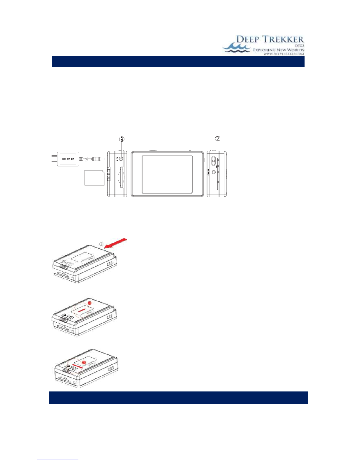
Optional Equipment – Digital Video Recorder (DVR)
The DVR is an essential tool for any ROV pilot, to record your investigations. Easily record your video to
an SD card (provided) and/or record voice-over comments to inspections (optional).
DVR Package Contents

DEEP TREKKER DTG2 USER MANUAL
DEEP TREKKER INC.
31
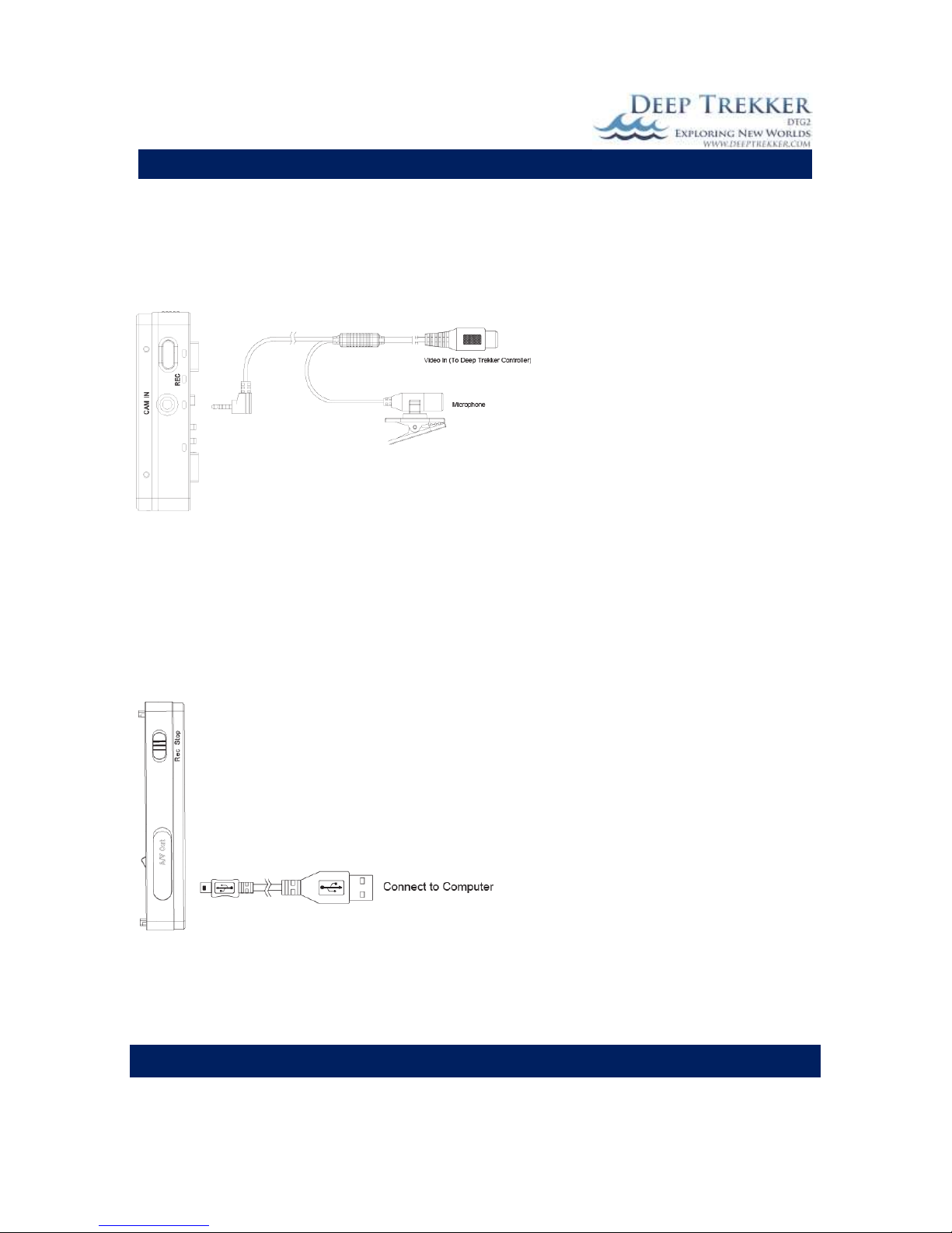
Recording from the Deep Trekker Controller to the DVR
1. Connect the RCA cable to the Video Out Port on the back of the Deep Trekker controller to ‘CAM
IN’
2. Press POWER button for 3 seconds to turn on DVR.
3. Green LED light illuminates to show the DVR is turned on.
4. Switch to REC (1) to start recording.
5. Switch to Stop (1) to stop recording.
Recording Settings
REC: Instead of switching the REC button, you can select
REC on the touch screen.
Take a Snapshot when recording video. The snapshot
will be stored in the image files.
ESC: Go back to main menu
Adjust settings of recording such as resolution, frames
per minute and to enable audio.
LOCK: Using the LOCK button beside the record switch, to
lock/unlock the touch screen.
DEEP TREKKER DTG2 USER MANUAL
DEEP TREKKER INC.
32
Charging the Battery
1. Connect the charger plug to the DC In Jack (9).
2. Plug the power cord of the charger to an AC wall outlet. The charging starts automatically.
3. The LED Bar (2) will illuminate red to show the device is in charging mode. Charging time
requires about 3 to 4 hours.
4. When charging is complete, the red LED indicator will turn off.
NOTE: You can also connect the DVR to your computer using the USB Cable to charge.
Installing and Removing the Battery
NOTE: This DVR has a removable battery. You can purchase extra batteries depending on your
application. Follow these instructions to remove or replace a battery.
1. To remove the battery, gently push the LOCK switch to the
right side and push the battery pack in the direction of the red
arrow.
2. To install a battery, attach the battery to the DVR and gently
push the battery back in the direction of the red arrow, then
slide the LOCK switch to the left.
DEEP TREKKER DTG2 USER MANUAL
DEEP TREKKER INC.
33
Connecting an External Microphone (Optional)
All Deep Trekker DVR Kits are shipped with an RCA cable with composite video connector (yellow). To
only record the video captured by the ROV camera, use the composite video connector (yellow) to
connect the DVR to the Deep Trekker controller.
To record voice-overs directly to your
inspections, you will need an RCA cable
with an incorporated microphone.
(Available from Deep Trekker)
Using the microphone-RCA cable,
connect the video connector to the Deep
Trekker controller as per step 3. The
integrated microphone can be clipped or
held. Speak into the microphone
normally.
Recording voice notes during the inspection saves you from re-watching the video and adding in
comments afterwards. The SD card can also act as a final product of documentation of your entire dive
for your customer.
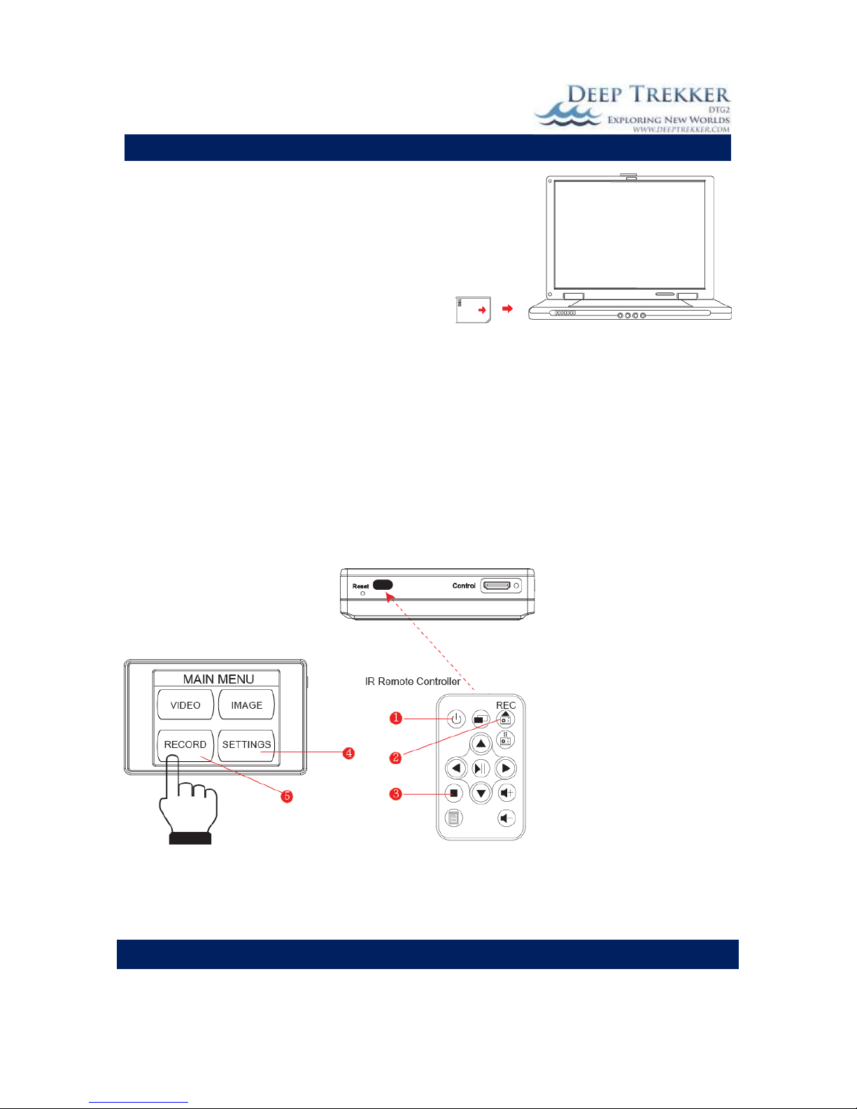
Connecting to Computer and Monitor
The live feed from the Deep Trekker Controller can be plugged into a larger monitor through the RCA
Port. These steps explain how to connect the DVR to a computer or monitor only.
1. Flip up the A/V out port cover. You will see
a USB port and an A/V out port
2. Insert USB Cable into the USB port, and the
other end to a computer. OR
3. Insert an A/V Cable into the A/V port and
the other end into a monitor or TV.
You can also insert Earphones into the AV-Out
Port and use it as a portable device.
DEEP TREKKER DTG2 USER MANUAL
DEEP TREKKER INC.
34
Retrieving Video Footage
Your video files are stored on the SD memory card.
When you are ready to edit or retrieve them, you can
do so in two ways.
1) Using a USB Cable to connect to a computer
2) Use a card reader to retrieve the files
Your computer will detect the SD card so you can
browse through your files to rename, copy/paste,
delete, edit, etc.
Using the Infrared Remote Controller and Editing Settings
1. Connect your Deep Trekker controller to the DVR & insert the memory card.
2. Turn on the DVR before using the IR remote controller.
3. Aim the IR Remote Controller at the sensor to control the device.
4. Press Rec (2) on the IR remote to start recording and press (3) to stop recording.
5. Press (3) again to return to the main menu page.
6. Enter Record Settings (5) to turn on Motion Detect.
7. Enter General Settings (4) to edit settings
8. To turn off the DVR, press the Power button (1), this button will not turn on the DVR.
You can also tap on the touch screen icons to edit the settings
DEEP TREKKER DTG2 USER MANUAL
DEEP TREKKER INC.
35
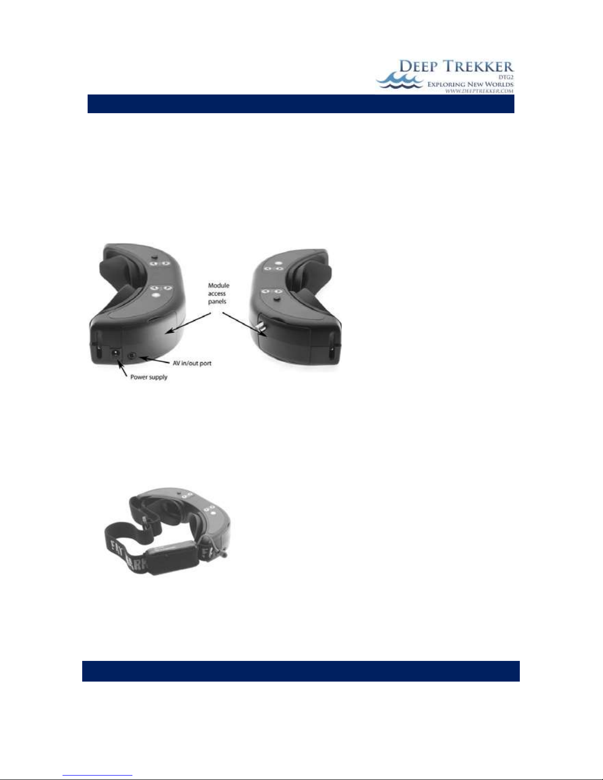
Optional Equipment – Video Glasses
The video glasses are a great addition when working in high sunlight. Although the LCD screen is 4 times
brighter than a laptop screen, the video glasses block out all of the light and allow you to view what the
DTG2 sees directly in front of your eyes like a TV screen.
The video glasses are plugged in from the AV in/out port on the video glasses into the front of the
controller to the RCA Video out port.
Fig. 12
The battery pack must also be plugged in for the video glasses to function. Plug the power cord from the
battery pack into the power supply outlet on the video glasses.
Note: Whenever the battery is plugged into the video glasses it is using power. It is important to unplug
the glasses when they are not in use to save the battery.
Fig. 13
To recharge the batteries, plug the power cord from the battery pack into the charger provided.
DEEP TREKKER DTG2 USER MANUAL
DEEP TREKKER INC.
36
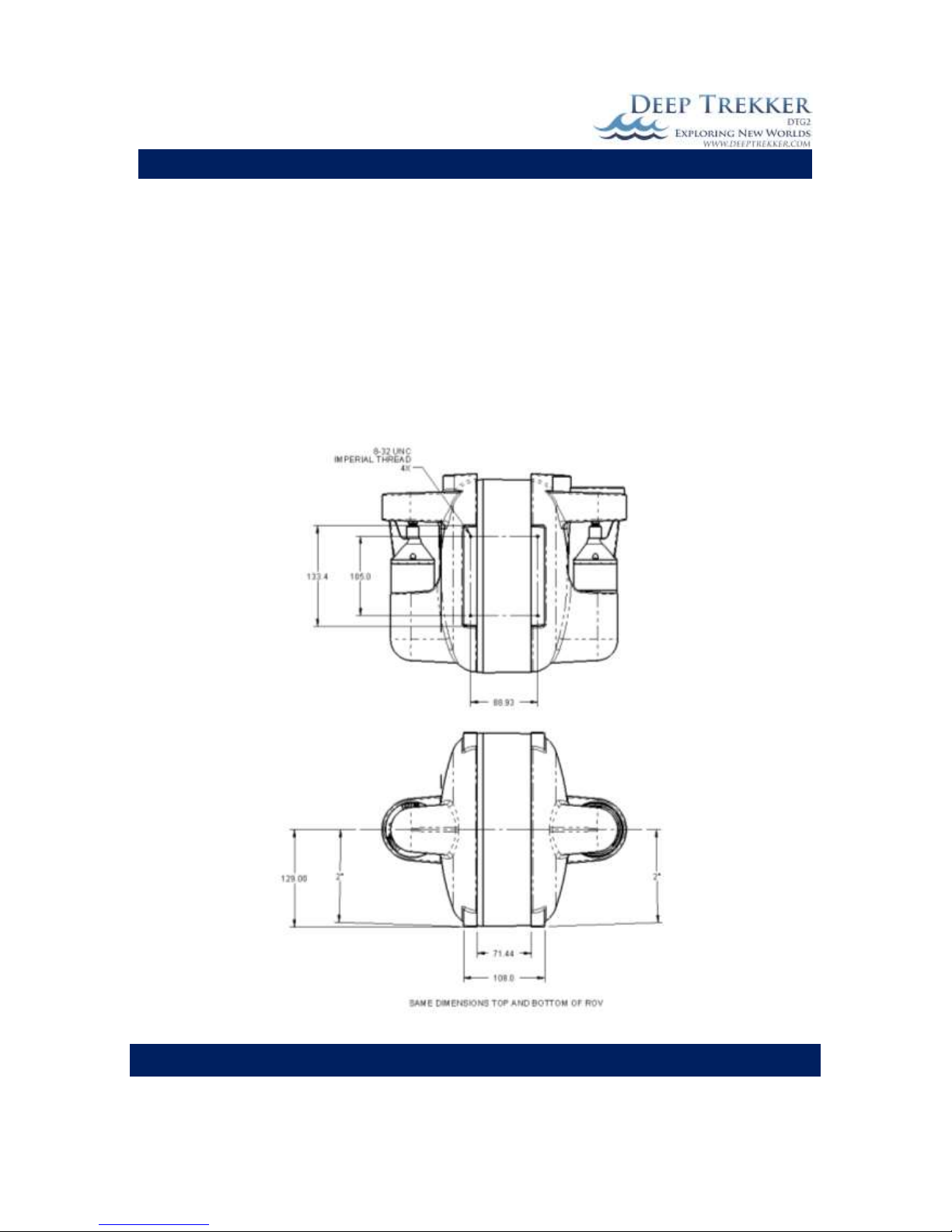
Mounting Provisions for Auxiliary Equipment
There are 4 threaded holes found in the top and bottom feet that can be used for mounting auxiliary
equipment. It is important that the underwater weight of any added equipment should not exceed 40
grams otherwise the fixed volume of the ROV will not be able to maintain neutral buoyancy. If the
equipment is heavier than this, the user is responsible for adding buoyancy to the ROV to compensate.
It is also advisable that this added equipment does not add significant additional drag to the upper or
lower portion of the ROV, or it will affect the dynamic characteristics of the ROV movement. Too much
drag at the top of the ROV will cause it to pitch up while in motion and too much drag on the bottom of
the ROV will cause it to pitch down while in motion. Below are the mounting dimensions of the
provided holes.
Fig. 14

DEEP TREKKER DTG2 USER MANUAL
DEEP TREKKER INC.
37
Maintenance
The owner is responsible for the everyday basic maintenance required in keeping the system in good
working order. Ensure that the system is cleaned after every dive and in the case of a salt water dive,
ensure it is rinsed well in fresh water. Do not use any sort of a cleaning agent on the window other
than fresh water. This high strength acrylic window is sensitive to chemical attacks which will
compromise the integrity of the structure. Never wash the ROV while it is being charged. The propeller
guards and propeller can be removed only as required to pull out debris causing binding. Under no
circumstance should the user unbolt a connection that includes an o-ring seal leading to the interior of
the ROV. Warranty is void if these seals are breached. This level of service must be left to an authorized
Deep Trekker Service Center. The owner should not unplug the tether from the ROV unless absolutely
necessary.

DEEP TREKKER DTG2 USER MANUAL
DEEP TREKKER INC.
38
Window Repair
Lightly scratched windows can be polished back to a state of optical clarity. If scratches or dents are
greater than 0.5mm deep, the window must be replaced due to the loss of structural integrity. For
scratches and dents 0.5mm or less you can repair the window while it is installed on the ROV using the
following method:
1) Protect the surrounding parts near the area to be worked on. Do not cover any part of the
window, only adjacent parts such as the side bodies.
2) Using a #1000 sandpaper, buff the scratch or dent out. Coarser sandpaper can be used if
required if the scratch or dent is significant.
3) Using a #2000 sandpaper, polish the area that was previously buffed with the coarser paper.
Continue to buff until no work marks are visible. The window surface should appear chalky
white at this point.
4) Using a paper towel or lint free cloth that is 100% free of any sort of grit, rub in a liquid polishing
compound that is compatible with Acrylic/PMMA plastic. Continue to polish until the window
appears optically clear.
DEEP TREKKER DTG2 USER MANUAL
DEEP TREKKER INC.
39
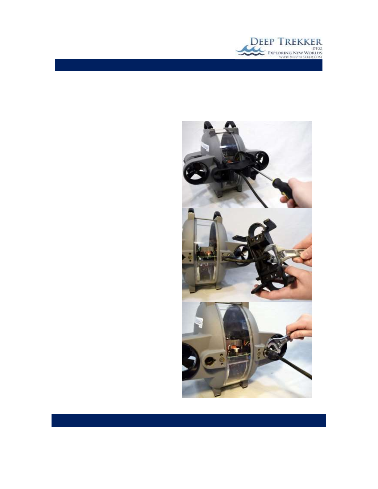
Removing the Tether
In general, the tether should not be removed from the DTG2 ROV. The carrying case is designed to hold
the DTG2, tether, and controller entirely in the one case. In the unlikely event that you do need to
remove the tether from the DTG2, follow the following steps to ensure no damage is caused to the
tether or DTG2:
1. Turn off ROV for service in a dry area.
2. Using a Phillips screw driver, remove the 4
screws holding the black bracket to the
rear of the ROV.
3. Using a 17mm wrench, unthread the nut
holding the tether on black bracket. Once
the nut is completely unthreaded, the
tether can be removed from the bracket.
4. Using a wrench, disengage the tether from
the ROV body. Place the wrench on the
steel hex next to the ROV body. Unthread
the nut, while supporting the tether
housing by hand ensuring that it does not
rotate with the nut. Continue to turn until
the tether is fully disengaged. It is
important to fix the rotation of the tether
using your hand or another tool. If the
tether is allowed to rotate while the
stainless steel nut is rotating, the pins will
be damaged and the ROV will need
extensive repair.
DEEP TREKKER DTG2 USER MANUAL
DEEP TREKKER INC.
40
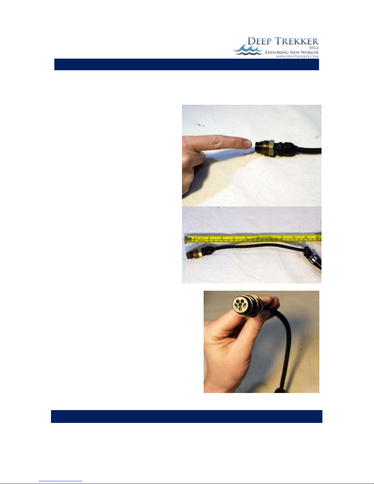
Re-Installing the Tether
Take extreme caution when removing and attaching the tether. If not done properly severe damage can
occur to the electrical pins.
1. Ensure the o-ring is defect free on the
tether that is about to be installed. Add a
saltwater resistant, o-ring compatible
grease to the o-ring, stainless steel nut
threads, and internal threads/bores that
the tether will slide into. Do not fill this
bore full of grease or a hydraulic lock will be
created when the tether is threading in and
damage can occur. Just add a thin layer of
grease to the surfaces.
2. Tie a knot in the tether about 250mm from
the end, to lock it behind the strain relief. If
this knot is not present, the cable will slip
through the gland and put an undesirable
side force on the connector.
3. Align the rotation of the tether connector
to the rotation of the mating pins inside the
ROV so that they properly engage when the
tether is threaded in.

DEEP TREKKER DTG2 USER MANUAL
DEEP TREKKER INC.
41
4. Insert the tether and by hand, turn the
stainless steel nut 5 complete turns while
holding the connector body directly behind
it, fixed from rotation. If the tether is
allowed to rotate while it is threading in,
damage can occur to the pins. Place the
wrench on the steel hex next to the ROV
body and turn until the nut is tight. It is
important to fix the rotation of the tether
using your hand or another tool. If the
tether is allowed to rotate while the
stainless steel nut is rotating, the pins will
be damaged and the ROV will need
extensive repair.
5. Fit the tether and gland into the black
bracket. Using a 17mm wrench, tighten the
gland securely on the bracket using the
provided nut.

DEEP TREKKER DTG2 USER MANUAL
DEEP TREKKER INC.
42
6. Fit the black bracket back onto the rear of
the ROV allowing the tether to route as
shown.
7. Fasten the black bracket onto the rear of
the ROV using the 4 screws and Philips
screw driver.
8. Turn on ROV and test all functions to
ensure proper operation.

DEEP TREKKER DTG2 USER MANUAL
DEEP TREKKER INC.
43
Trouble Shooting
Below is a trouble shooting guide. If none of the possible solutions work, please contact Deep Trekker
support or your authorized Deep Trekker Dealer for assistance.
Problem
Possible Solutions
Pitch Joystick not working and ROV
pointing up in water
1) Ensure the 2 shipping screws are not engaged.
See Section Delivery and Inspection
ROV turning left or right when
attempting to drive straight forward
2) Adjust the thruster trim. See section Thruster
Trim under Operation.
ROV sitting too forward or back when
in water
1) Adjust the trim of the pitch. In some instances you
might want the ROV to hold a slight pitch forward
when picking up an object. See section Pitch Trim.
Window fogged
1) Move to better atmospheric conditions.
2) Possible breach in hull - contact Deep Trekker
support or your authorized Deep Trekker Dealer
for assistance.
Water or water drops inside ROV
1) Possible breach in hull - contact Deep Trekker
support or your authorized Deep Trekker Dealer
for assistance.
LED – low ROV battery
1) Charge ROV battery using provided ROV charger.
LED – low controller battery
1) Charge controller battery using provided
controller charger.
LED – pitch stall
**Press reset thrusters/pitch servo button to re-
activate**
1) Ensure shipping screws are not engaged.
2) Ensure tether is not pulling on ROV.
3) Ensure ROV is in the water.
LED – right thruster stall
**Press reset thrusters/pitch servo button to re-
activate**
1) Remove ROV from water and turn off system.
Inspect propellers for debris that may be
preventing rotation. Remove guarding and
propellers as necessary to inspect. Ensure
everything and everyone is clear of the propellers
when the system is turned on again.
LED – left thruster stall
**Press reset thrusters/pitch servo button to re-
activate**
1) Remove ROV from water and turn off system.
Inspect propellers for debris that may be
preventing rotation. Remove guarding and
propellers as necessary to inspect. Ensure
everything and everyone is clear of the propellers
when the system is turned on again.

DEEP TREKKER DTG2 USER MANUAL
DEEP TREKKER INC.
44
LED - no communication
(on constantly or erratic flashing)
1) Look for damaged tether.
2) ROV is currently charging and unusable.
3) Batteries are low - charge ROV.
4) Remove tether and try diagnostic cable. See
section Diagnostics Cable.
LED - no communication
(quickly flashing)
1) Possible breach in hull - contact Deep Trekker
support or your authorized Deep Trekker Dealer
for assistance.
Thrusters weak
1) Inspect propellers and guarding for debris causing
blockage of water flow. Remove as necessary.
2) Charge ROV.
ROV floats or sinks
1) Add or remove ballast plates as outlined in the
user manual. Ensure any external equipment is
neutrally buoyant.
Video feed not working
1) Retrieve ROV from the water and test video again.
Video footage of water with nothing in the
background can appear black as though the video
is not working.
2) Check connections between the controller and
viewing system. Ensure all connectors are
completely pushed in.
3) Charge the viewing system batteries.
4) Ensure a splitter is not being used. Composite
video output on the controller is only capable of
driving one monitor.
Controller computer system frozen in
‘ON’ state or acting unusual
1) Reset the system by disconnecting the controller
batteries for at least 10 seconds.
ROV computer system frozen in ‘ON’
state or acting unusual
1) Reset the system by disconnecting the batteries
for at least 10 seconds. This is accomplished by
plugging in the charger.
ROV charger LED not turning red when
plugged in
1) Ensure the ROV battery is not at 100% (unused
after last charge).
2) Check the integrity of the 2 charge pins in the
ROV charge port for corrosion.
3) Ensure by use of multi-meter that the charger is
22.2VDC on the output pins.

DEEP TREKKER DTG2 USER MANUAL
DEEP TREKKER INC.
45
Using the Diagnostics Cable
If the LED no communication light is illuminated, using the diagnostics cable is the best way to
understand where the issue may be. In the top of the Deep Trekker carrying case is a secured
diagnostics cable. This cable is used to determine if a fault is caused from within the ROV itself or by a
problem in the tether.
Remove the tether from the ROV, as outlined in the manual section Removing the Tether, then connect
the diagnostics cable to the ROV. Connect your controller to the other end of the diagnostics cable, and
turn on the ROV.
If the ROV functions properly with the diagnostics cable attached, there is a fault within the tether. If
you are still experiencing communications issues the fault is most likely something within the ROV or
controller.
This is valuable information for you, Deep Trekker support and/or your authorized Deep Trekker Service
Center to know prior to sending a system in for service.

DEEP TREKKER DTG2 USER MANUAL
DEEP TREKKER INC.
46
Diagnostics Screens
The Diagnostics Screens are helpful for troubleshooting. For example, if the thruster joystick is being
pushed forward and the thrusters are not moving, various data within these screens can help narrow
down the problem. Here, you can also monitor the system voltages as well as the current
draws from each motor.
To access the Diagnostics Screens, Press the MENU button and then Select Diagnostics
The DTG2 uses separate battery and electrical systems the ROV itself and within the controller. The
systems communicate with each other via RS485 in operation. Since the sensors are not on a system
that has motors or any “noisy” devices, the readings are very clear. The systems are as follows:
POWER
CONTROLLER VDC battery level controller (nominal 11.1 VDC)
ROV MAIN VDC battery level ROV (nominal 19.2 VDC)
RIGHT current draw FR thruster motor (normally 0 – 8000ma)
LEFT current draw RR thruster motor (normally 0 – 8000ma)
COMMUNICATIONS
CURRENT DIVE MIN current dive time in minutes
LAST DIVE last dive time in minutes
SYSTEM for factory use only
ROV communication status of ROV (OK/FLT)
BUTTONS
ON/OFF status of ON/OFF button (1=ROV on, 0=ROV off)
LIGHTS status of PRIMARY/AUX floodlights (1= on, 0=off)
RESET status of reset button (1=on, 0= off)
CAM TRACK status of camera forward button (1=on, 0= off)
PIT LOCK status of pitch lock button (1=on, 0= off)
CAM UP/DN status of camera up/down button (1=on, 0= off)
CAM LOCK status of camera lock to body button (1=on, 0= off)
ARW UP/DN status of gain up/down buttons (1=on, 0= off)
GRAB O/C status of grabber open/close buttons (1=on, 0= off)
GRAB CW/CCW status of grabber cw/ccw buttons (1=on, 0= off)
1 status of aux function 1 button (1=on, 0= off)
2 status of aux function 2 button (1=on, 0= off)
CONTROLLER
HEADING heading of the controller (0-359 degrees) (optional)
PITCH target pitch for ROV set by controller (-90 to +90 degrees)
TH R target right thruster power set by controller (-100% to +100%)
TH L target left thruster power set by controller (-100% to +100%)
TA HEAD target heading set by controller (0-359 degrees)
TA DEPTH target depth set by controller (0-305m [0-1000ft])

DEEP TREKKER DTG2 USER MANUAL
DEEP TREKKER INC.
47
GAIN gain level set by controller (4-10)
M LIGHT primary flood light intensity set by controller (fixed 100%)
A LIGHT auxiliary flood light intensity set by controller (0% to +100%)
TH-JS-X right hand joystick x raw voltage 8 bit Analog to Digital Conversion (ADC) value (0-1023)
TH-JS-Y right hand joystick y raw voltage 8 bit Analog to Digital Conversion (ADC) value (0-1023)
P-JS-X left hand joystick x raw voltage 8 bit Analog to Digital Conversion (ADC) value (0-1023)
P-JS-X left hand joystick y raw voltage 8 bit Analog to Digital Conversion (ADC) value (0-1023)
ROV
LEAK leak sensor on the ROV for the main body (1=leak , 0 = no leak)
LOW BAT low battery warning for the ROV battery (1=low battery , 0 = normal or full battery)
BAT LEV an approximation of the ROV battery level (0-100%)
A PITCH the actual pitch of the ROV as measured by the pitch sensor (-90 to +90 degrees)
TA R the target right thruster power set by the ROV after auto-heading adj.(--100% to +100%)
TA L the target left thruster power set by the ROV after auto-heading adj.(--100% to +100%)
ST PITCH indicates a pitch motor stall fault (1=pitch motor stalled, 0 =pitch motor OK)
TH STALL R indicates a right thruster motor stall fault (1=motor stalled, 0 = motor OK)
TH STALL L indicates a left thruster motor stall fault (1=motor stalled, 0 = motor OK)
ST ROTATE indicates a grabber rotate motor stall fault (1=motor stalled, 0 = motor OK)
ST O/C indicates a grabber open/close motor stall fault (1=motor stalled, 0 = motor OK)
DEEP TREKKER DTG2 USER MANUAL
DEEP TREKKER INC.
48
Parts and Service
To order replacement parts for the DTG2 exploration system, use the order numbers in the
Replacement Parts List that follows. Replacement parts are available only as listed and can be
purchased from an authorized Deep Trekker dealer or directly from Deep Trekker at
Support@Deeptrekker.com.
Replacement parts for the system that are only repairable by an authorized Deep Trekker repair center
are not listed in this user manual. If the DTG2 is in need of one of these parts, please contact Deep
Trekker support or your authorized Deep Trekker dealer for assistance.
*The serial number of the DTG2 will be required when ordering parts. Locate the serial number on the
label found on the inside of the hull.*
Part
Number
Description
Photo
5677
CONTROLLER
, DTG2
0058-XXX
TETHER
5550
(22.2V)
CHARGER,
ROV

DEEP TREKKER DTG2 USER MANUAL
DEEP TREKKER INC.
49
5005
(12.6V)
CHARGER,
CONTROLLER
0036
WEIGHT,
BUOYANCY
ADJUSTMEN
T
0278
PLUG, PORT
W/O-RING
6120
PORT PLUG
CHARGE
0456
PROPELLER

DEEP TREKKER DTG2 USER MANUAL
DEEP TREKKER INC.
50
Warranty
DEEP TREKKER INCORPORATED WARRANTY - LIMITED WARRANTY
Deep Trekker Incorporated ("Deep Trekker"), warrants to you, the first retail purchaser of this Deep
Trekker exploration system, that it will repair or replace defects in materials or workmanship that occur
and are reported to Deep Trekker or your factory authorized dealer within the applicable warranty
periods set forth below, subject to the "What This Warranty Does Not Cover" section below. Warranty
coverage is applicable only to products purchased from factory authorized Deep Trekker dealers. Your
acceptance of delivery of the warranted Deep Trekker exploration system constitutes your acceptance
of the terms of this limited warranty. This warranty gives you legal rights which may vary from region to
region.
Factory Installed parts and components: Warranty Period runs for one (1) year of first retail purchaser.
The Warranty Period runs from the date of delivery to the first retail customer provided that the Deep
Trekker exploration system is delivered within twenty four (24) months from the date of manufacture.
For Deep Trekker exploration systems delivered more than twenty four (24) months after the date of
manufacture, coverage will end at thirty six (36) months after the date of manufacture.
This warranty is extended to the original retail purchaser only. A purchase receipt or other proof of date
of original purchase is required before warranty or service is performed.
This limited warranty is the sole and exclusive express warranty from Deep Trekker. Under the laws of
certain states or provinces, there may be no implied warranties from Deep Trekker covering your Deep
Trekker exploration system, and all implied warranties (INCLUDING ANY IMPLIED WARRANTY OF
MERCHANTABILITY OR FITNESS FOR A PARTICULAR PURPOSE) are excluded and disclaimed where
allowed by law. Any implied warranties arising under applicable law are LIMITED IN DURATION TO THE
APPLICABLE PERIOD OF THIS WRITTEN WARRANTY AND ARE EXPRESSLY DISCLAIMED AFTER THE
EXPIRATION OF THE WARRANTY PERIOD. NOTE: SOME STATES OR PROVINCES DO NOT ALLOW
LIMITATIONS ON HOW LONG AN IMPLIED WARRANTY LASTS, SO THE ABOVE LIMITATION MAY NOT
APPLY TO YOU. There are no warranties which extend beyond the description on the face hereof.
What This Warranty Does Not Cover:
1. A product including its components that has been altered or modified so as to adversely
affect its operation, performance or durability.
2. A product including its components that has been serviced by an unauthorized repair center.
3. Damage caused by improper maintenance or reassembly.
4. Damage or failure caused during shipment, or by acts of God, acts of war, or other such
occurrence beyond either parties control.
5. Any damage resulting from an impact with another object.
6. Partial cuts of tether.
7. Severed tether and any resultant loss of the exploration system.

DEEP TREKKER DTG2 USER MANUAL
DEEP TREKKER INC.
51
8. Any damage to components not designed for underwater use that has been breached by
water, including viewing systems, controllers, battery packs, chargers, ETC.
9. Windows worn from normal use.
10. Windows that have experienced a chemical attack.
11. Window breakage due to the operation of a damaged window and the resulting damage to
system. A damaged window would include deep scratches or a window that has
experienced a chemical attack.
12. Hull breakage due to the operation of a damaged hull and the resulting damage to system.
A damaged hull would include deep scratches, pits or dents.
13. Hull plating including blisters, cracks, peeling or scratches.
14. Any product which has been misused, used in a negligent manner, used without normal
maintenance or operated contrary to any instruction furnished by Deep Trekker.
15. Loss of time, inconvenience, retail charges, travel expense, loss of use, loss of profit, loss of
or damage to personal property, retrieval fees for lost systems, or other remedies not
specifically allowed.
Repairs will only be authorized after Deep Trekker is satisfied that there is a defect in material or
workmanship.
Your sole and exclusive remedy under this express warranty or any applicable implied warranty is the
repair or replacement, at Deep Trekker's sole discretion, of parts and components covered by this
warranty, and does not include incidental or consequential damages, which are specifically
DISCLAIMED AND EXCLUDED from warranty coverage. Note: SOME STATES OR PROVINCES DO NOT
ALLOW THE EXCLUSION OR LIMITATION OF INCIDENTAL OR CONSEQUENTIAL DAMAGES, SO THE
ABOVE LIMITATION OR EXCLUSION MAY NOT APPLY TO YOU. Any legal action alleging a breach of any
applicable warranty coverage must be brought within one (1) year from the date the alleged breach first
occurred.
Returning Goods
To obtain warranty service, you must a) return your Deep Trekker exploration system, including any
alleged defective part, along with proof of purchase to an authorized Deep Trekker dealer or b) contact
the Deep Trekker Factory direct, within the applicable warranty period to obtain warranty service.
a. The Deep Trekker dealer will carry out the warranty procedures on the owner's behalf. All
warranty work will be performed at an authorized dealer. The owner is responsible for the
expense associated with transporting the Deep Trekker exploration system to and from the
repair facility.
b. Contact Support@Deeptrekker.com with a detailed explanation of the problem, including
pictures and the product serial number. Once the problem has been determined to be
warrantable, Deep Trekker will reply with an RMA (Return Material Authorization) number and
an address to ship the related goods to. In this case the owner is responsible for the shipping
expense to the repair facility only, while Deep Trekker will cover the return shipping to a
maximum of 100 United States dollars.

DEEP TREKKER DTG2 USER MANUAL
DEEP TREKKER INC.
52
This document contains the entire warranty given by Deep Trekker. Deep Trekker does not authorize
any person or persons, including Deep Trekker dealers, to change the terms of this express limited
warranty, which is Deep Trekker's only warranty. Deep Trekker reserves the right to change or improve
the design or manufacture of Deep Trekker products without obligation to modify any products
previously manufactured.
Deep Trekker, Inc.
40 Melair Road
Ayr, Ontario Canada
N0B1E0
 Loading...