


®
Wide-i SeaCam
®
Operator’s Manual
DEEPSEA
POWER & LIGHT
T: (858) 576-1261
F: (858) 576-0219
4033 Rufn Road
San Diego, CA
92123- 1817 USA
Wide-i SeaCam
Record product serial number below as it appears on the nameplate.
Serial #
Connector Type
Pin-outs
● Ground = Pin
● PWR = Pin
● Video = Pin
www.deepsea.com
sales@deepsea.com
®
Original Instruction - 1
REV 8/7/13
Wide-i SeaCam
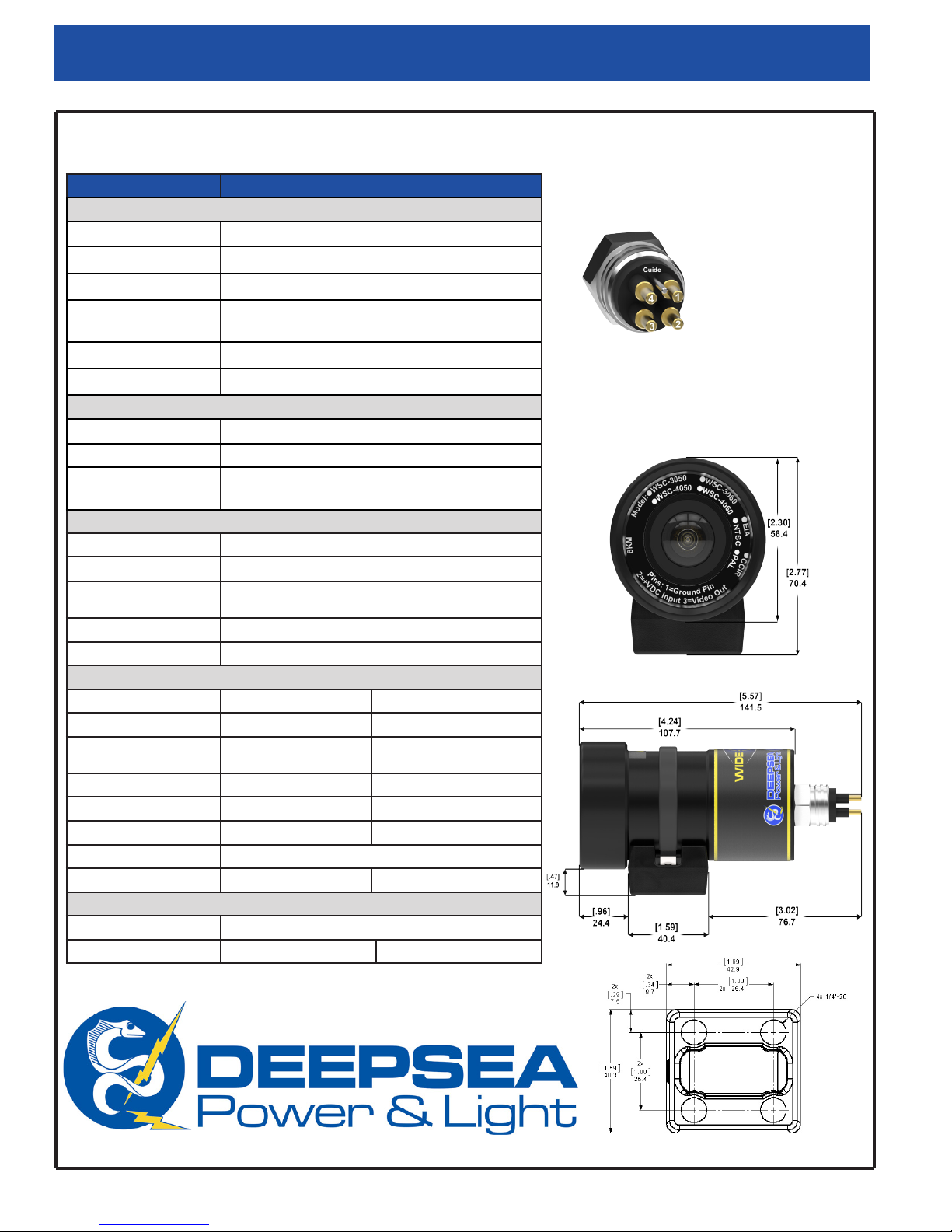
Specication Overview
Mechanical Specications
Housing
Port
Outer Diameter
Overall Length
(w/o connector)
Weight in Air
Weight in Water
®
Operator’s Manual
Standard Connector
6013-T 8 AL
Optically Polished Glass
58.4 mm (2.30 in)
107.7 mm (4.24 in)
0.542 kg (1.196 lbs.)
0.29 kg (0.639 lbs.)
MCBH4MP
1 = Ground
2 = Power
3 = Video
4 = Not Used
*Other connectors and pin-out
options are available upon
request.
Environmental Specications
Depth Rating
Operating Temp.
Storage
Temperature
Optical Specications
Lens
Focus
Depth of Field
FOV in Air
FOV in Water
Video Specications
Image Sensor
Number of Pixels
Resolution
Scene Illumination
1/3 inch CCD Sensor 1/3 inch CCD Sensor
EIA: 811 (H) x 508 (V)
CCIR: 795 (H) x 596 (V)
570TVL (center) 450 TVL (center)
0.002 Lux F1.4 0.1 Lux F1.2
Signal to Noise
Video Output
Video Format
Composite, 1.0 Vp-p 75 ohm, unbalanced
EIA or CCIR NTSC or PAL
Electrical Specications
Power
Current
Dimensions
6000 m (20,000 ft)
-10º C to 40º C (-14º F to 104º F)
-30º C to 70º C (-22º F to 158º F)
TBD
Fixed Focus
Air: 3.8 cm (1.5 in) to innity
Water: 2.5 cm (1.0 in.) to innity
160º (H) x 146º (V)
125º (H) x 89º (V)
B/W Color
NTSC: 811 (H) x 508 (V)
PAL: 795 (H) x 596 (V)
46 dB More than 50 dB
11-30 V DC
160 mA 145 mA
®
2
* Specications subject to change without notice.
®
[inch]
mm

Operator’s Manual
Wide-i SeaCam
®
Table of Contents
Specification Overview 2
Table of Contents 3
Safety Symbols 4
General Notes and Warnings 4
Pre & Post Dive Inspection 4
Operation Procedures 4-5
Operation Instruction 4-5
Camera Output 5
Flooding Repair Procedure 5
Troubleshooting 5
RMA Procedure for Repair 6
Warranty Information 6
Limited Waranty 6
3

Wide-i SeaCam
®
Operator’s Manual
Safety Symbol
In this operator’s manual and on the product, safety symbols are used to communicate important
safety information. This section is provided to improve understanding of these symbols.
This is the safety alert symbol. It is used to alert you to potential personal injury hazards. Obey all safety messages that follow this symbol to
avoid possible injury or death.
DANGER
! WARNING
CAUTION
NOTICE
This symbol means read the operator’s manual carefully before using the equipment. The operator’s manual contains important information
on the safe and proper operation of the equipment.
This symbol means always wear safety glasses with side shields or goggles when handling or using this equipment to reduce the risk of eye
injury.
This symbol indicates the risk of electrical shock.
DANGER indicates a hazardous situation which, if not avoided, could result in death or serious injury.
WARNING indicates a hazardous situation which, if not avoided, could result in damage to the product or bodily harm.
CAUTION indicates a hazardous situation which, if not avoided, could result in minor or moderate injury.
NOTICE indicates information that relates to the protection of property.
General Notes and
Warnings
The Wide-i SeaCam supports a variety of connectors,
camera modules, depth ratings, and pin-outs. By looking
into the front port of the camera, the user can see the
model, depth rating, video format as well as the pin out
orientation. Be sure to verify pin-out orientation before
use.
It is very important when preparing the system for
deployment that the cable, at both the camera and
topside ends, be carefully dressed to provide complete
strain relief to the connectors. Failure of the strain relief
provisions will almost certainly damage the connectors
and possibly other elements of the system.
DANGER
WARNING
Never place the camera in a vice or other hard
clamping tool. Should it become necessary to hold
the camera more tightly than can be managed by
hand, use a clean, good quality strap wrench.
Pre and Post Dive Inspection
Rinse your Wide-i SeaCam in fresh water after use in
saltwater.
Always check to make sure that the rear bulkhead
connector assembly is secured before deployment.
Before and after each deployment, check the following
areas for damage, wear or corrosion:
● Rear bulkhead connector assembly
● Video cable
● Front window
● Retaining cowl
Do not operate any high voltage electrical equipment
in or around water without using a Ground Fault
Interrupt circuit (GFI) and an isolation transformer,
especially when divers are in the water.
4
Operation Procedures
Operation Instruction
1. Prepare a power supply with 11-30V DC output.
2. Plug the red [positive(+)] and black [negative(-)]
banana plugs of the camera cable into their
respective jacks on the power supply.

Operator’s Manual
Wide-i SeaCam
®
3. Plug the BNC connector on the topside of the
cable into the monitor or VCR video-in jack (a
BNC-to-RCA adapter may be required by the
monitor/VCR in use).
4. Lubricate the camera bulkhead connector with
an appropriate silicone lubricant (spray type
recommended), and using a linear motion plug
the female inline connector into the male bulkhead
connector on the back of the camera.
5. Screw the locking sleeves together firmly (hand
tight-do not use tools). The camera is now ready
for operation; switch the power supply ON to power
the camera. The camera draws approximately
160 mA of current during operation, and will work
when supplied between 11-30 volts DC.
Camera Output
The Wide-i SeaCam does an exceptional job at giving
a high quality wide angle image even in very low light
conditions. This camera is capable of producing an
incredible 125° (H) x 89° (V) degree field of view under
water. Just like with any wide angle lens, users should
be aware of vignetting effect (black corners).
below shows a standard still image taken from the Wide-i
SeaCam clearly showing the vignetting effect on the four
corners of image.
Figure 1
Flooding Repair Procedure
If the camera stops working while underwater, you
should assume that it has been flooded. When working
on a potentially flooded camera, it is important to use
appropriate personal protective equipment to include, at
a minimum, eye and hand protection.
1. Immediately turn off the power to the unit.
2. Open the housing by removing the rear end capretaining ring. Grasp the rear end cap in one
hand and the camera housing in the other. With
care, separate the two components using a linear
motion. If required gently twist components while
separating.
3. Pour out any water trapped in the housing.
4. If the camera is completely flooded, rinse the
internal components with clean fresh water in order
to minimize contamination and corrosion.
5. Allow parts to dry in air or a convection oven set
at 60° C (190° F). IMPORTANT! DeepSea Power
& Light cannot be responsible for any damage
incurred during emergency field repairs. Such
repairs should be undertaken only as a last resort
and by qualified personnel.
Figure 1: Sample Image
DANGER
After each deployment, carefully check
to make sure the camera has not flooded. It is
possible for the camera to partially flood and then
reseal itself while underwater. Upon surfacing, the
camera can become internally pressurized, which
may be potentially dangerous. Additionally, if the
power remains on when the camera has partially
flooded, it is possible for electrolytic generation of
an explosive mixture of hydrogen and oxygen gases.
If a camera appears flooded upon removal from the
water, it should be treated as potentially dangerous.
Point the camera away from persons and valuable
equipment and make sure that the power is
disconnected. See the Flooding Repair Procedure
for more information.
Troubleshooting
1. If the camera stops working while underwater
assume that it has been flooded. See Flooding
Repair procedure.
2. Once it has been determined that the camera is
not flooded, or if it does not turn on during predeployment checks, troubleshoot in the following
sequence:
a. Check the cable/inline connector to make
sure that correct voltage and current are
being supplied, and that the correct sockets
are being used. See page 2 of this manual for
electrical specs and connector pin-outs.
b. Remove the connector. Inspect the assembly
for visual signs of wear. Use a multi-meter
check for continuity or shorts in the connector.
Try a spare connector, if available.
c. Check the wires that go from the power
supply to the camera base for wear. If they
appear worn, replace them.
d. Check to make sure that the power supply
board is securely attached to the camera. If
it is loose, check for damage on the board. If
there appears to be no damage, reattach the
board to the camera. Try using a spare driver
board if available.
e. If the camera still does not work, return it to
DSPL using the RMA Procedure.
5

Wide-i SeaCam
®
Operator’s Manual
RMA Procedure for Repair
Should it be necessary to return your camera to the
factory, follow the procedure for the Flooded Camera
Repair above, and by leaving the connector partially
unscrewed. For warranty and non-warranty repairs
please contact DeepSea Power & Light for a RMA
number prior to returning your item. Please have your
light model number, serial number and any other
pertinent information along with a description of the
problem, on hand when you call, or include them in a
fax or e-mail. When shipping your item, be sure that the
freight is pre-paid (CODs will not be accepted) and that
the RMA number is clearly printed on the outside of the
box. All shipments should be sent to the address below:
DeepSea Power & Light
Attn: RMA ####
4033 Ruffin Road
San Diego, CA 92123-1817
U.S.A
Tel: (858) 576-1261
Fax: 858-576-0219
e-mail: RMA@deepsea.com
Seller to any information, representation, or warranty
concerning the goods sold under this contract, and
unless an affirmation, representation, or warranty
made by an agent, employee, or representative is
specifically included within this contract, it will not be
enforceable by Buyer. If notice of defect is given to
DeepSea Power & Light, Inc. within such 90 day or one
year warranty period, the sole obligation of DeepSea
Power & Light, Inc. shall be to furnish new or repaired
parts free of charge in exchange for parts which have
been proved defective and does not include any other
costs such as the cost of removal of the defective part,
installation, labor, or consequential damages of any
kind, the exclusive remedy being to require DeepSea
Power & Light, Inc. to furnish such new parts. Under
no circumstances shall the Buyer be entitled to recover
any incidental damages as that term is defined in
Commercial Code §2715.
Warranty Information
Limited Warranty
Seller warrants that the goods (except internal electronic
components) sold under this contract will be free from
defect in material and workmanship for a period of one
year from the date of shipment from the factory, if they
have been properly used. Internal electronic components
are warranted for 90 days from the date of shipment
from the factory, if they have been properly used. This
warranty will be limited to the repair or replacement of
parts and the necessary labor and services required
to repair the goods. IT IS EXPRESSLY AGREED
THAT THIS WARRANTY WILL BE IN LIEU OF ALL
WARRANTIES OF FITNESS AND IN LIEU OF THE
WARRANTY OF MERCHANTABILITY. This warranty
is the exclusive and only warranty to pass with the
goods under this contract. No agent, employee, or
representative of the Seller has any authority to bind
DEEPSEA
POWER & LIGHT
®
4033 Rufn Road
T: (858) 576-1261
F: (858) 576-0219
6
San Diego, CA
92123- 1817 USA
www.deepsea.com
sales@deepsea.com
 Loading...