

Page 1
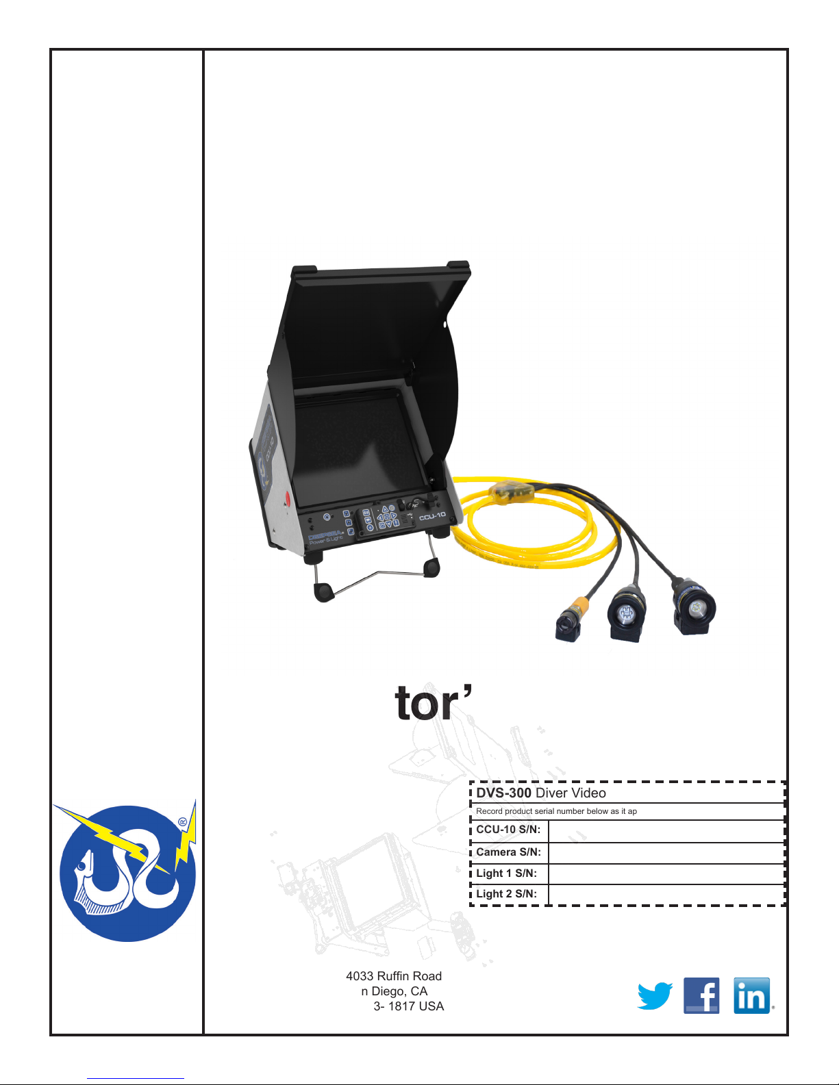
DVS-300
®
Diver Video System
Operator’s Manual
DEEPSEA
POWER & LIGHT
T: (858) 576-1261
F: (858) 576-0219
4033 Rufn Road
San Diego, CA
92123- 1817 USA
DVS-300 Diver Video System
Record product serial number below as it appears on the nameplate.
CCU-10 S/N:
Camera S/N:
Light 1 S/N:
Light 2 S/N:
www.deepsea.com
[email protected]
Original Instruction - 1
REV 8/20/13
Page 2
DVS-300
Diver Video System
[inch]
mm
Operator’s Manual
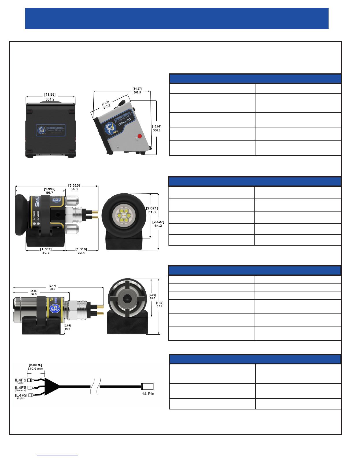
Specication Overview
Camera Control Unit (CCU-10)
Weight w/o Batteries: 5.4 kg (12 lbs.) Safety: Low voltage DC to diver
Size: Length: 362.5 mm (14.27 in.)
Width: 301.2 mm (11.86 in.)
Height: 306.8 mm (12.08 in.)
Power:
100–240V AC, 50/60Hz (60W)
Battery Type:
18V Li-Poly Rechargeable
Monitor: 12.1” Color VGA with audio Temperature:
Connections:
Back panel connections for umbilical.
Recorder: Thumb Drive
Audio: Internal mic & line audio in
0° C to 40° C (32° F to 104° F)
Light (SeaLite Six-R)
Weight in Air: 300.3 g (10.6 oz) UV LEDs (optional): 365 & 405nm
Weight in Water: 232.2 g (8.2 oz) Beam Pattern: 87° Flood
Depth Rating: 6000 m (19, 685 ft.) Housing: 6013-T8 AnodizedAluminum
White LEDs: 1200 Lumens typical
Color Temp: 6000° K
Camera (Nano SeaCam)
Weight in Air: 99.8g (3.52 oz) Power Consumption: 1W max
Weight in Water: 81.6 g (2.88 oz) Scene Illumination: 0.04 Lux
Depth Rating: 6000 m (19,685 ft.) Resolution: 620 TVL
Housing: 6013-T8 Anodized Aluminum
or 6Al-4V Titanium (optional)
Lens: 2.54 mm Fixed Focus
(Proprietary Optics)
Focus in water:
10.16 cm (4.0 in.) to innity
Cable
Conductors:
3x #16 AWG power conductor & 1x #22
AWG 75 ohm coax
Length: 100 m (328 ft.) Standard
200 m (656 ft.) optional
Diameter: 1.09 cm (0.430 in.)
Specications subject to change without notice.
*
Video Output:
Composite 1.0Vp-p 75 ohm unbalanced
Image Sensor:
1/3” SONY Color CCD II 410K
Materials: Yellow polyurethane jacket
Breaking Strength:
150 lbs. minimum
2
Page 3

Operator’s Manual
DVS-300
Diver Video System
Table of Contents
Safety Symbols 5
General Safety Rules 5-6
Work Area Safety 5
Electrical Safety 5
Personal Safety 5-6
Equipment Use and Care 6
Battery Use and Care 6
Service 6
Specific Safety Information 7
DVS-300 Safety 7
Description, Standard Equipment, and Optional Equipment 7- 8
Description 7
Standard Equipment 7
Optional Equipment 8
CCU-10 Components 8
Keypad and Icon Legends 9
Camera Components 10
LED Light Components 10
Pre-Dive Inspection 10
Post-Dive Inspection 10
Work Area and Equipment Set Up 11- 16
CCU-10 Placement 11
Tilt Stand 11
Front Cover 11
Opening the Front Cover 11
Closing the Front Cover 12
Connecting the DVS-300 12
External Monitor 12
USB Port 12
Powering the DVS-300 12
Battery Power 12-13
Checking Battery Status: LEDs 13
Outlet Power 13
Assembling the Quick Release Helmet Mounts 13-14
Interface Overview 14-16
Navigating 14-15
3
Page 4

DVS-300
Operator’s Manual
Diver Video System
Table of Contents Continued
LED Toogle Switch Key 15
Microphone Mute Key 15
Screen 15-16
Operating Instructions 16-19
Starting Up the DVS-300 16
Jobs 16-18
Recording Video 16-17
Taking Photos 17
Annotating an Inspection by Voice 17
Reviewing Images and Video 17
Completing a Dive 17-18
Adjusting Settings 18-19
Adjusting Monitor Settings 18
Adjusting Video Format 18
Adjusting Language Preference 18
Adjusting Report Creating Preference 18-19
Maintenance Instructions 19-20
Cleaning 19
Accessories 19
Transport and Storage 19
Service and Repair 19-20
Warranty 20
Disposal 20
Battery Disposal 20
Troubleshooting 20
Notes 21
4
Page 5
Operator’s Manual
DVS-300
Diver Video System
Safety Symbol
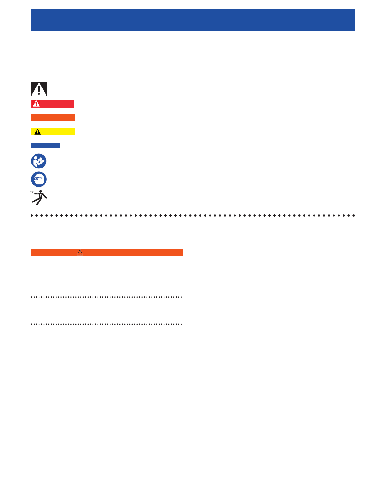
In this operator’s manual and on the product, safety symbols are used to communicate important
safety information. This section is provided to improve understanding of these symbols.
This is the safety alert symbol. It is used to alert you to potential personal injury hazards. Obey all safety messages that follow this symbol to
avoid possible injury or death.
DANGER
! WARNING
CAUTION
NOTICE
This symbol means read the operator’s manual carefully before using the equipment. The operator’s manual contains important information on
the safe and proper operation of the equipment.
This symbol means always wear safety glasses with side shields or goggles when handling or using this equipment to reduce the risk of eye injury.
This symbol indicates the risk of electrical shock.
DANGER indicates a hazardous situation which, if not avoided, could result in death or serious injury.
WARNING indicates a hazardous situation which, if not avoided, could result in damage to the product or bodily harm.
CAUTION indicates a hazardous situation which, if not avoided, could result in minor or moderate injury.
NOTICE indicates information that relates to the protection of property.
General Safety Rules
WARNING
Read all safety warnings and instructions. Failure to
follow the warnings and instructions may result in
electric shock, re, and/or serious injury.
SAVE THESE INSTRUCTIONS!
Work Area Safety
● Keep your work area clean and well lit. Cluttered
or dark areas invite accidents.
● Do not operate equipment in explosive
atmospheres, such as in the presence of
flammable liquids, gases, or dust. Equipment can
create sparks which may ignite the dust or fumes.
● Keep children and bystanders away while
operating equipment. Distractions can cause
accidents.
Electrical Safety
● Avoid body contact with earthed or grounded
surfaces. There is an increased risk of electrical
shock if your body is earthed or grounded.
● Do not expose CCU-10, its batteries, and its
charger to rain or wet conditions. Water that enters
the equipment will increase the risk of electrical
shock.
● Do not abuse the cord. Never use the cord for
carrying, pulling, or unplugging the power tool.
Keep cord away from heat, oil, sharp edges,
and moving parts. Damaged or entangled cords
increase the risk of electric shock.
● If operating equipment in a damp location is
unavoidable, use a ground fault circuit interrupter
protected supply to reduce the risk of electric
shock.
● Keep all electrical connections dry and off the
ground. Do not touch equipment or plugs with wet
hands to reduce the risk of electrical shock.
Personal Safety
● Stay alert, watch what you are doing, and use
common sense when operating equipment. Do
not use equipment while you are tired or under
the influence of drugs, alcohol, or medication. A
5
Page 6

DVS-300
Diver Video System
Operator’s Manual
moment of inattention while operating equipment
may result in serious personal injury.
Equipment Use and Care
● Do not force equipment. Use the correct equipment
for your application. The correct equipment will do
the job better and safer at the rate for which it is
designed.
● Do not use equipment if the power switch does not
turn it ON and OFF. Any equipment that cannot be
controlled with the power switch is dangerous and
must be repaired.
● Disconnect the plug from the power source and/
or the battery pack from the equipment before
making adjustments, changing accessories, or
storing. Preventive safety measures reduce the
risk of injury.
● Store idle equipment out of the reach of children
and do not allow persons unfamiliar with the
equipment or these instructions to operate the
equipment. Equipment can be dangerous in the
hands of untrained users.
● Maintain equipment. Check for misalignment or
binding of moving parts, missing parts, breakage
of parts, and any other condition that may affect
the equipment’s operation. If damaged, have the
equipment repaired before use. Many accidents
are caused by poorly maintained equipment.
● Use the equipment and accessories in accordance
with these instructions; taking into account the
working conditions and the work to be performed.
Use of the equipment for operations different
from those intended could result in a hazardous
situation.
● Use only accessories that are recommended by
the manufacturer for your equipment. Accessories
that may be suitable for one piece of equipment
may become hazardous when used with other
equipment.
● Keep handles dry, clean, and free from oil and
grease. This allows for better control of the
equipment.
Battery Use and Care
● Use equipment only with specifically designated
battery packs. Use of any other battery packs may
create a risk of injury and fire.
● Do not probe battery with conductive objects.
Shorting of battery terminals may cause sparks,
burns, or electrical shock. When the battery pack
is not in use, keep it away from other metal objects,
like paper clips, coins, keys, nails, screws or other
small metal objects that can make a connection
from one terminal to another. Shorting the battery
terminals together may cause burns or a fire.
● Under abusive conditions, liquid may eject from
battery; avoid contact. If contact occurs, flush
with water. If liquid contacts eyes, seek medical
help. Liquid ejected from the battery may cause
irritation or burns.
● Use and store batteries and chargers in dry,
appropriate temperature areas. Extreme
temperatures and moisture can damage batteries
and result in leakage, electrical shock, fire or
burns.
● Do not cover charger while in use. Proper ventilation
is required for correct operation. Covering charger
in use could result in fire.
● Properly dispose of batteries. Exposure to high
temperatures can cause the batteries to explode;
do not dispose of in a fire. Some countries have
regulations concerning battery disposal. Follow all
applicable regulations.
Service
Ensure a qualied repair person services your equipment
using only identical replacement parts to maintain
the safety of the tool. Remove the batteries and refer
servicing to qualied service personnel under any of the
following conditions:
● If liquid has been spilled or objects have fallen
into product.
● If the product does not operate normally when
following the operating instructions.
● If the product has been dropped or damaged.
● When the product exhibits a distinct change in
performance.
● Recharge only with the charger specified by the
manufacturer. A charger suitable for one type of
battery pack may create a risk of fire when used
with another battery pack.
6
Page 7

Operator’s Manual
!
DVS-300
Diver Video System
Specic Safety Information
This section contains important safety information
that is specic to the DVS-300. Read these precautions
carefully before using the DVS-300 to reduce the risk
of electrical shock, re, or other serious personal
injury.
WARNING
SAVE ALL WARNING AND INSTRUCTIONS
FOR FUTURE REFERENCE!
Keep this manual with the equipment for use by the operator.
DVS-300 Safety
● An improperly grounded electrical outlet can
cause electrical shock and/or severely damage
equipment. Always check the work area for a
properly grounded electrical outlet. The presence
of a three-prong or GFCI outlet does not ensure
that the outlet is properly grounded. If in doubt,
ensure a licensed electrician inspects the outlet.
● Only power the CCU-10 with the specified battery
or a double insulated power supply.
● Do not operate this equipment if operator or
machine is standing in water. Operating machine
while in water increases the risk of electrical shock.
● The DVS-300 is not waterproof. Only its lights,
camera, and cable are waterproof. To decrease
the risk or electrical shock, do not expose the
surface equipment to water or rain.
● Do not use where a danger of high voltage contact
is present. The equipment is not designed to
provide high voltage protection and isolation.
● Read and understand this operator’s manual and
the instructions for any other equipment in use,
and all warnings before operating the DVS-300.
Failure to follow instructions may result in property
damage and/or serious personal injury.
● Practice diver safety. Ensure proper fit and function
of all diving gear and equipment before diving.
● Ensure proper seal on diving helmet. If mounting
the DVS-300 lights and camera onto a dive
helmet faceplate, ensure proper torque values
are achieved in accordance to the safety
specifications. In accordance with Kirby Morgan
specifications in March 2013, proper faceplate
torque value should be 20psi for fiberglass model
helmets. This information is subject to change.
Please check with helmet manufacturer for current
information about your helmet specification.
● The CCU-10 is intended for indoor use when
powered by the AC power supply. When powered
by battery, protect the CCU-10 from exposure to
weather. Do not bend or kink the cable. This can
cause a break or tear in the cable and lead to
shorting and malfunction.
● To prevent damage to the product and to decrease
the risk of injury, do not expose equipment to
mechanical shocks.
The warnings, cautions, and instructions discussed
in this operator’s manual cannot cover all possible
conditions and situations that may occur. It must be
understood by the operator that common sense and
caution are factors which cannot be built into this
product, but must be supplied by the operator.
Description, Specications,
and Standard Equipment
Description
The Diver Video System 300 (DVS-300) is a portable
monitor, camera and lighting system designed to be
everything a diver needs to capture video, audio and still
images. The DVS-300 allows the user to easily transmit
the data collected into an HTML report onto a USB thumb
drive. The DVS-300 features real time display and audio
inputs while recording video in order to comment on the
video being captured.
The DVS-300 features readily accessible controls to
adjust light brightness, camera and display all from the
surface unit. The DVS-300 is the all in one tool for diving
research and maintenance needs.
Standard Equipment
● One Camera/Light Control Unit (CCU-10)
● Two LED Lights
● One Camera
● 100m Cable
● One 16 GB Thumb drive
7
Page 8
DVS-300
Diver Video System
Operator’s Manual
Optional Equipment
● 200m Cable (Other custom lengths are available
upon request.)
● Brackets
● Hand-held Pistol Grip
● Li-Ion Batteries
● Battery Charger
● UV LED Light
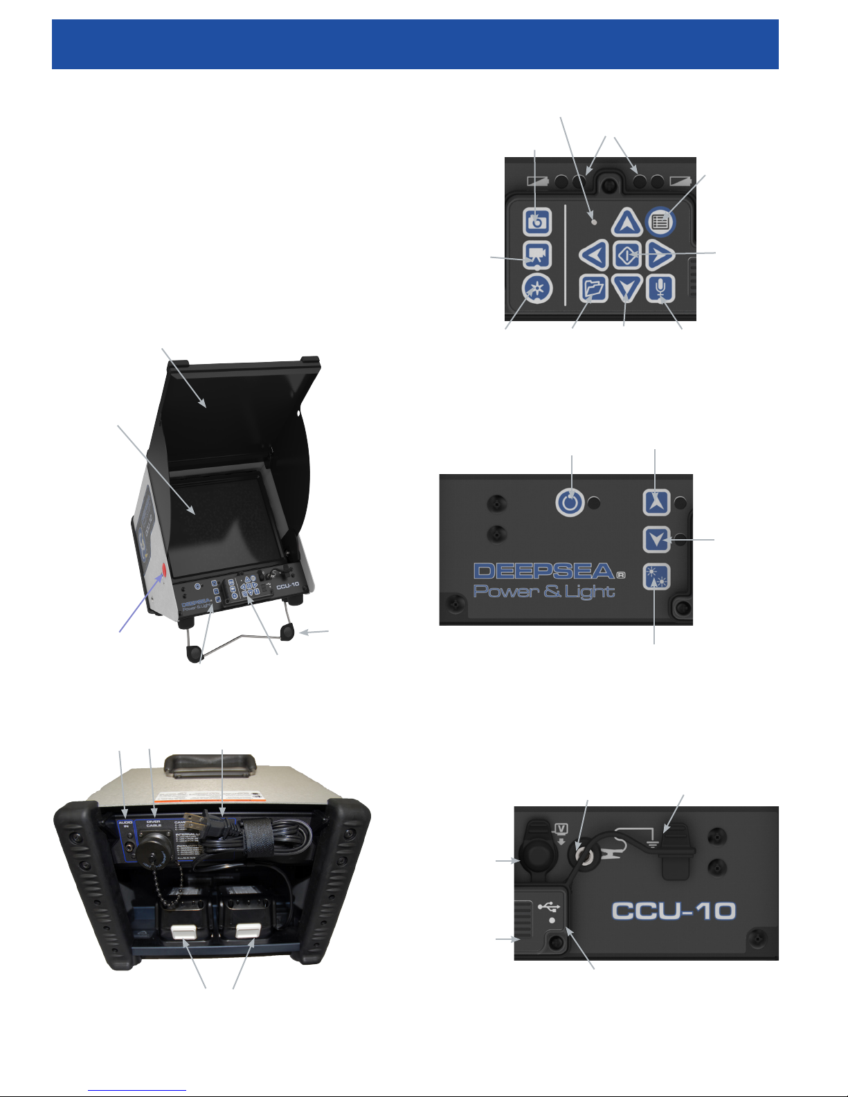
CCU-10 Components
Front Cover
LCD Screen
Microphone
Battery Indicator LEDs
Arrow Key
Key
Video Key
Autolog Key
Photo Key
Job Manager
Figure 3 - CCU-10 Main Keypad
Light Dimmer
Power
Menu Key
Select Key
Internal Microphone
Mute Key
(Increase)
Front Cover
Release Buttons
Mini Keypad
Figure 1 - Front View (Open)
External Audio In
Cable
Connection
Power Cord
Main Keypad
Tilt Stand
Figure 4 - Mini Keypad
Terminal
Video Out
Light Dimmer
(Decrease)
Light Toogle
Switch
Ground
USB Cap
Batteries
Figure 2 - Rear View
8
Speaker
Figure 5 - Connections
USB Port
Page 9
Operator’s Manual
DVS-300
Diver Video System
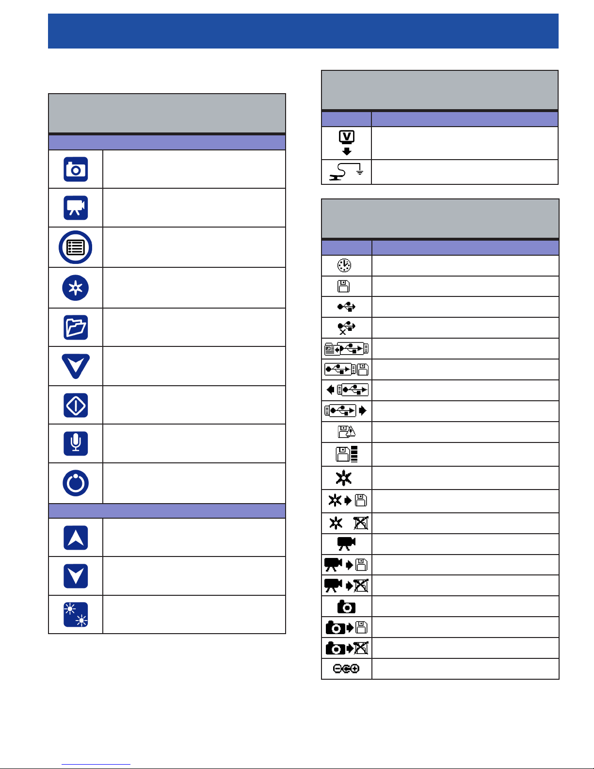
Keypad and Icon Legends
Table 1
CCU-10 Keypad Icons
Main Keypad
Photo Key
Video Key
Menu Key
Autolog Key
Job Manager Key
Table 2
CCU-10 Connection Icons
Icon Denition
Video Out
Ground Connection
Table 3
CCU-10 Screen Icons
Icon Name / Meaning
Loading Icon
Saved Icon
USB Icon
Corrupt Thumb Drive in USB Port Icon
Job Saving Icon
Arrow Keys
Select Key
Internal Microphone Mute Key
Power
Mini Keypad
Light Dimmer (Increase)
Light Dimmer (Decrease)
Light Toggle Switch
Saving to USB Icon
Insert Thumb Drive
Thumb Drive Ejected Icon
Thumb Drive Error
Thumb Drive Full Icon
Autolog Icon
Autolog Saving Icon
Autolog Not Saved Icon
Video Icon
Video Saving Icon
Video Not Saved Icon
Photo Icon
Photo Saving Icon
Photo Not Saved Icon
External Power Icon
9
Page 10
DVS-300
!
!
Diver Video System
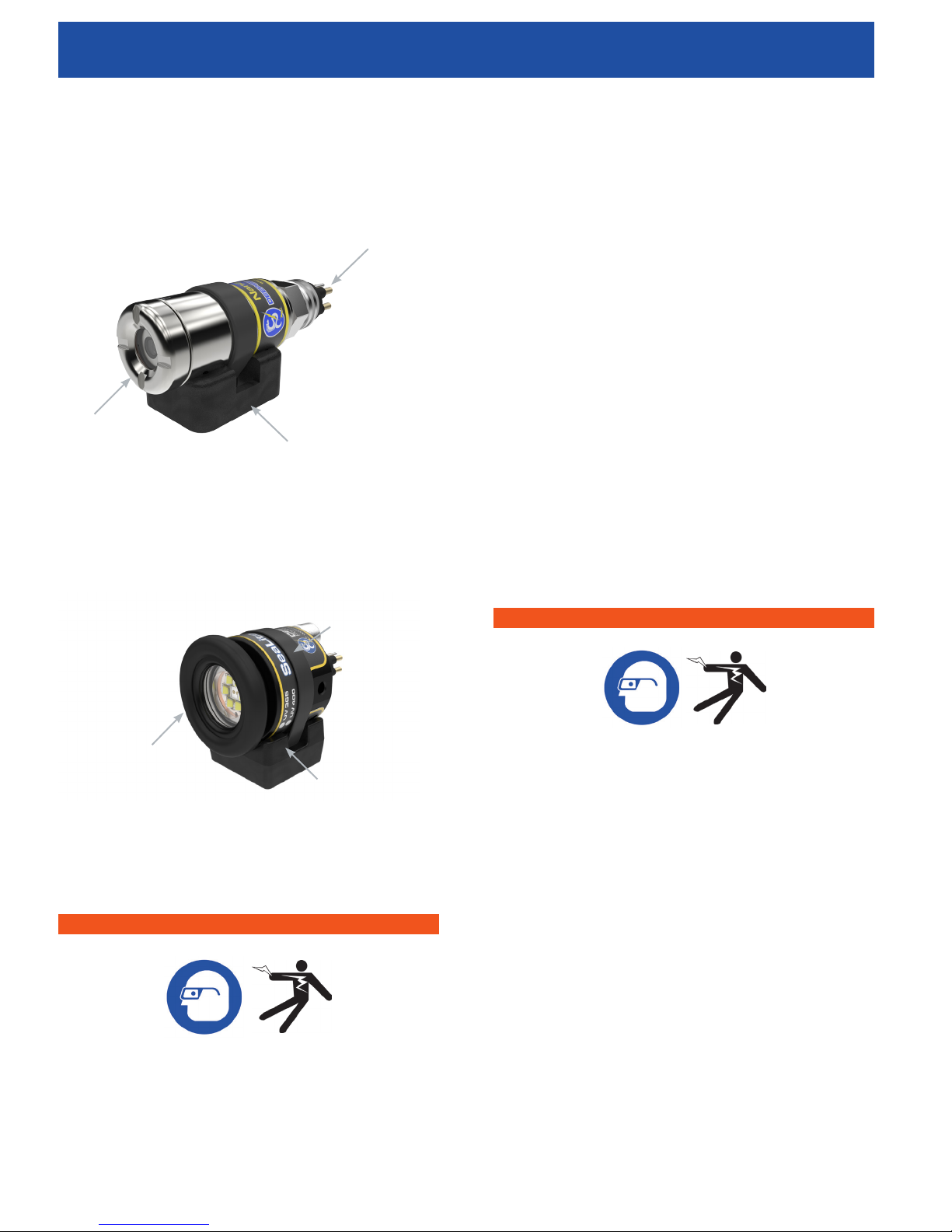
Camera Components
Front Port
Bracket
Figure 6 - Front View
Connector
Operator’s Manual
1. Confirm that the power is OFF, that any external
power and cords are disconnected, and that the
batteries are removed. Inspect the cords, cables,
and connectors for damage or modification.
2. Clean any dirt, oil, or other contamination from
the CCU-10, LED lights and the camera to ensure
proper functionality.
3. Inspect the DVS-300 for any broken, worn, missing,
misaligned or binding parts, or any other condition
which might prevent safe, normal operation.
4. Check to make sure all rear bulkhead connectors
are secure before deployment.
5. Check the following areas on your LED Lights and
camera for previous damage, wear or corrosion:
rear bulkhead connector, power cable, and front
window.
6. Inspect any other equipment being used per its
instructions to make sure it is in good, usable
condition.
7. If any problems are found, do not use the unit until
the problems are corrected.
LED Light Components
Connector
Front Port
Bracket
Figure 7 - Front View
Pre-Dive Inspection
WARNING
Before each use, inspect your DVS-300 and correct
any problems to reduce the risk of serious injury
from electrical shock or other causes and prevent
machine damage.
Post-Dive inspection
WARNING
After each use, inspect your DVS-300 to ensure
proper machine function.
1. Confirm that the power is OFF, that any external
power and cords are disconnected, and that the
batteries are removed. Inspect the cords, cables,
and connectors for damage.
2. Ensure that the connectors are still in working
order and cleaned of any dirt and residue from the
dive.
3. Insert dummy plugs to protect the pins and cable
during transit.
4. Rinse your LED lights and camera in freshwater
after use in saltwater.
5. Wipe down the assembly with a microfiber cloth
and a light cleaning solution to avoid salt buildup.
6. Install the dustcap on the CCU-10’s rear 14 pin
connector.
10
Page 11
Operator’s Manual
!
DVS-300
Diver Video System
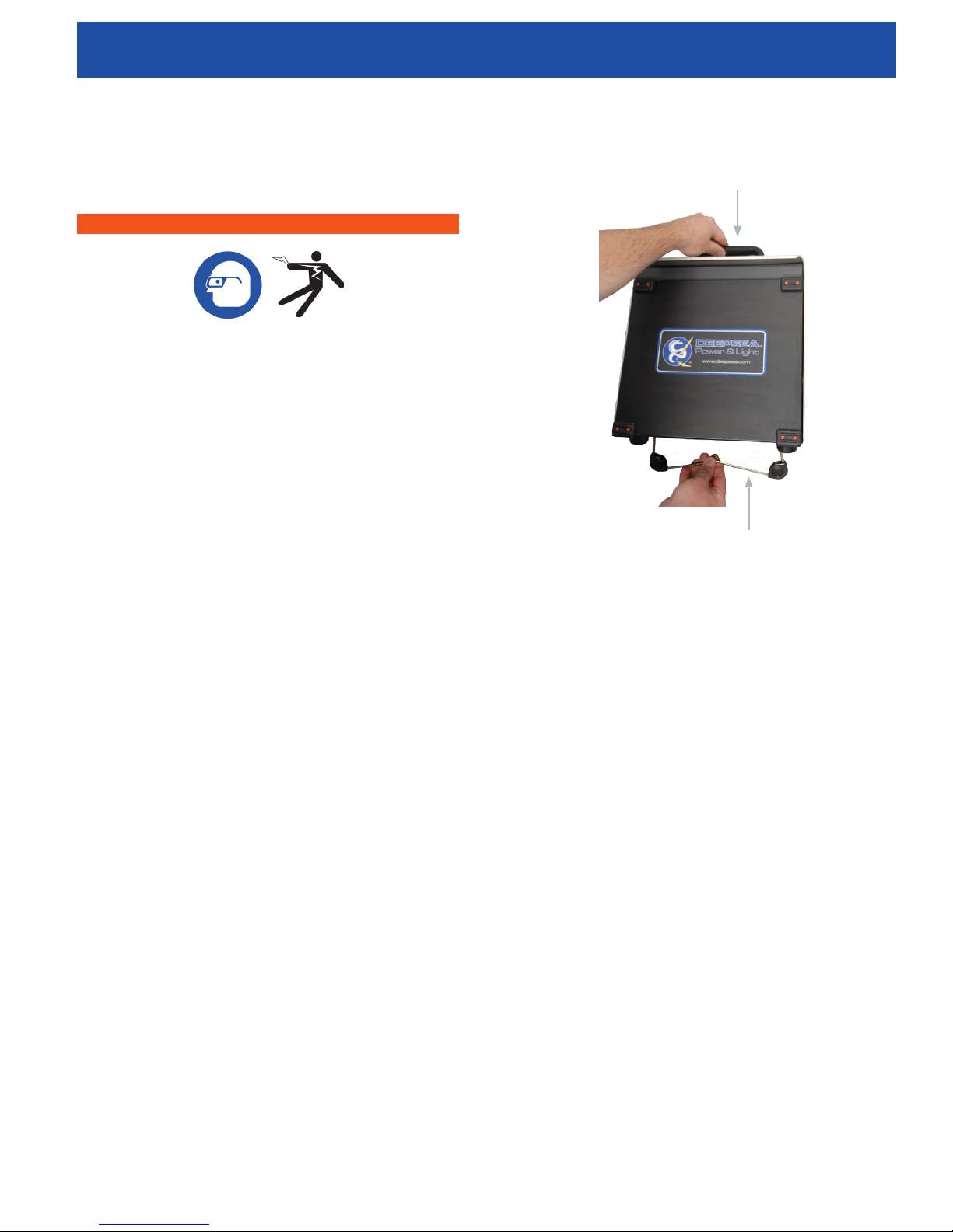
stand until it locks in place (See Item 2, Figure 8)
Work Area and Equipment Set
Up
WARNING
Set up the DVS-300 and work area in accordance
with these procedures to reduce the risk of injury
from electrical shock, re, and other causes and to
prevent damage to the DVS-300.
1. Check work area for the following:
a. Adequate lighting.
b. Flammable liquids, vapors, or dust that may
ignite. If present, do not work in area until
sources have been identified and corrected.
The CCU-10 is not explosion proof. Electrical
connections can cause sparks.
c. Clear, level, stable dry place for operator. Do
not use the machine while standing in water.
d. If using external power, clear path to the
electrical outlet that does not contain any
potential sources of damage for the power
cord.
2. Ensure the equipment has been inspected as
specified by the operator’s manual.
3. Evaluate the work area and erect barriers as
necessary to keep bystanders away. Bystanders
can distract the operator during use.
CCU-10 Placement
Item 1
Item 2
Figure 8 - Setting Up the Tilt Stand
To store the tilt stand, tilt the unit back slightly, and push
the tilt stand toward the back of the unit until it lays at
against the base of the unit.
Front Cover
The CCU-10 front cover serves two purposes: it protects
the unit during transport and storage, and it acts as a sun
hood to reduce glare during inspections.
Place the CCU-10 in an area and in a position that allows
easy access during an inspection. To reduce the risk
of electrical shock and equipment damage, ensure the
placement location is dry. The CCU-10 is not waterproof
and exposure to wet conditions can cause electrical
shock or equipment damage.
Tilt Stand
To set up the tilt stand, perform the following:
1. Use the handle on the top of the CCU-10 to place
the unit in the desired location (See Item 1, Figure
8).
2. Tilt the unit back slightly and pull forward on the tilt
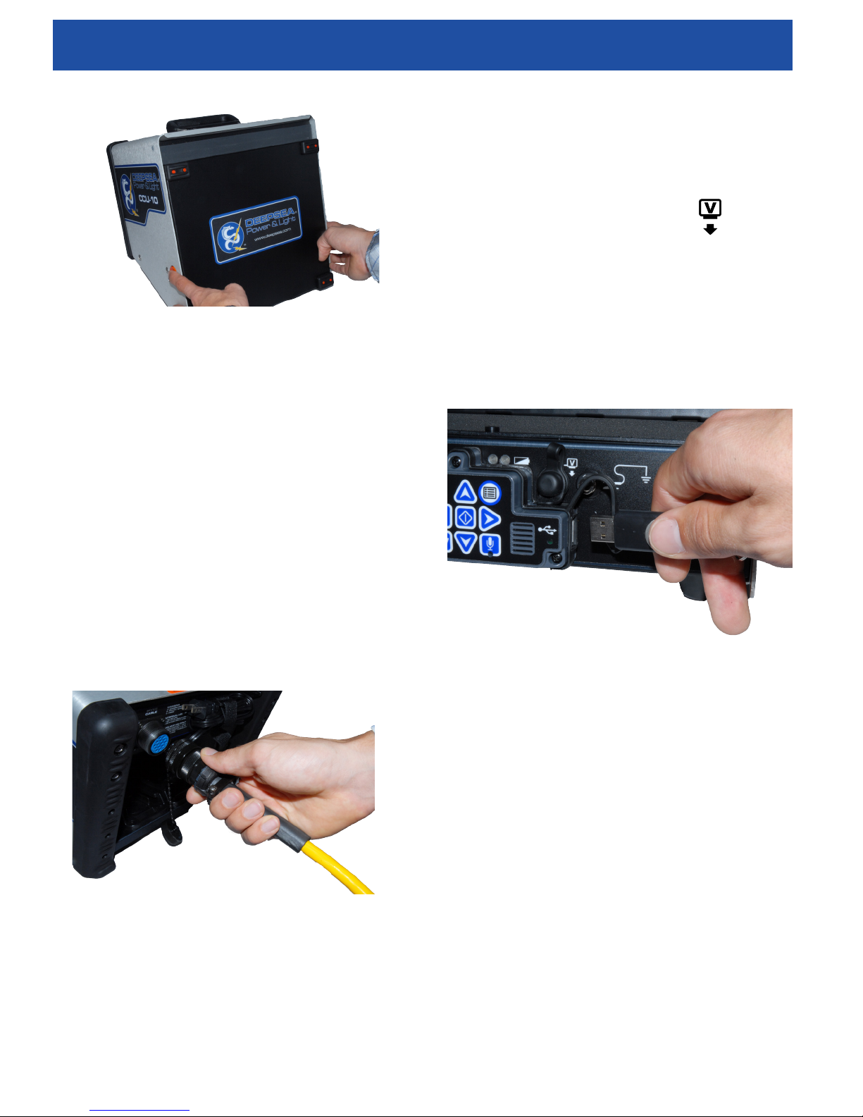
Opening the Front Cover
To open the front cover, perform the following:
1. Depress the orange Front Cover Release Buttons
on each side of the unit (See Figure 9).
2. Raise the front cover to its uppermost position
where it will lock securely into place.
11
Page 12
DVS-300
Diver Video System
Figure 9 - Opening the Front
Closing the Front Cover
To close the front cover, perform the following: Disconnect
all connections, including the USB devices. Keeping clear
of the front cover, gently depress the orange buttons to
drop the cover to the lowest position. Press the cover into
place until it locks.
Operator’s Manual
External Monitor
The DVS-300 may be used with an external monitor by
connecting an RCA cable from the video input port on the
external monitor. Connect the other end of the cable to
the yellow CCU-10 video output port on the front of the
CCU-10 marked with the Video Out Icon .
USB Port
Insert a thumb drive into the USB port to store images and
video captured by the DVS-300 (See Item 1, Figure 11).
When the thumb drive is being accessed, the USB LED
will blink steadily. The USB LED will be ON steadily when
ready for use.
Connecting the DVS-300
1. Unwrap the diver cable and pull out the 14 pin
connector end.
2. Insert 14 pin male diver cable end in the
appropriate position into the CCU-10. (Note: The
connecter is keyed for proper alignment.)
3. Connect the LED light and the camera to the
appropriate connection on the diver’s end.
Figure 10 - CCU-10 Connector
Figure 11 - USB Port with Thumb Drive
Powering the DVS-300
The DVS-300 can either be powered with Li-Polymer
rechargeable batteries or with the external power cord. To
reduce the risk of electrical shock, use battery power as
the preferred powering method and only install batteries
or plug in the power cord with dry hands. Never operate
the unit from AC power while the CCU-10 is in a wet
environment.
Battery Power
12
To operate the DVS-300 using battery power, insert
one or two fully charged batteries onto the battery dock
located on the back of the CCU-10. Ensure the battery
locks onto the dock.
When fully charged, one 18 V Li-Polymer battery rated
Page 13

Operator’s Manual
DVS-300
Diver Video System
at 2.2 Ah will power the DVS-300 for approximately
1.75 hours; and two batteries will power the DVS-300
for approximately 4.5 hours during normal usage. Actual
battery operation time will vary with battery rating and
use.
If operating the DVS-300 on AC power and if at least
one battery is also installed, the External Power Icon will
appear in the Status Overlay for 3 seconds if the DVS-
300 is disconnected from AC power to indicate the switch
to battery power.
Checking Battery Status: LEDs
The CCU-10 has four battery indicator LEDs, two for each
battery, located just below the screen (See Figure 12).
Table 4
Battery Status LED Indicators
Left LED is OFF
Right LED is red
Blinking red and
beeps
Solid red &
continuous tone
Slow blink External power in use.
Battery low
Replace batteries immediately.
Shutdown in 1 minute.
Dead batteries.
Shutdown in 5 seconds.
Beeps when disconnected.
Outlet Power
To operate the DVS-300 using AC power, locate the
power cord on the back of the unit. Unhook the Velcro®
strap and remove the plug from its holder (See Figure
13).
Figure 12 - Battery Indicator LEDs
When the unit is turned ON and batteries are in the
battery docks, the battery indicator LEDs on the DVS-300
will reect the state of each battery as shown in Table 4 to
put a box around the LED lights in this image.
Table 4
Battery Status LED Indicators
LED Behavior Meaning
Left LED is green
Right LED is OFF
Left LED is green
Right LED is red
Battery fully charged
Battery partially charged
Figure 13 - Power Cord and Power Cord Wrap
Plug the power cord into a standard outlet. If using an
extension cord no greater than 25 ft [7.6 m], ensure
the cord has a gauge of at least 18 AWG. If using an
extension cord greater than 25 ft [7.6 m], ensure the cord
has a gauge of at least 16 AWG.
Assembling the Quick Release Helmet
Mounts
If you do not have a quick release mount and mechanism,
mount the light and camera directly to the helmet mounts
or to the DeepSea diver universal hand grip.
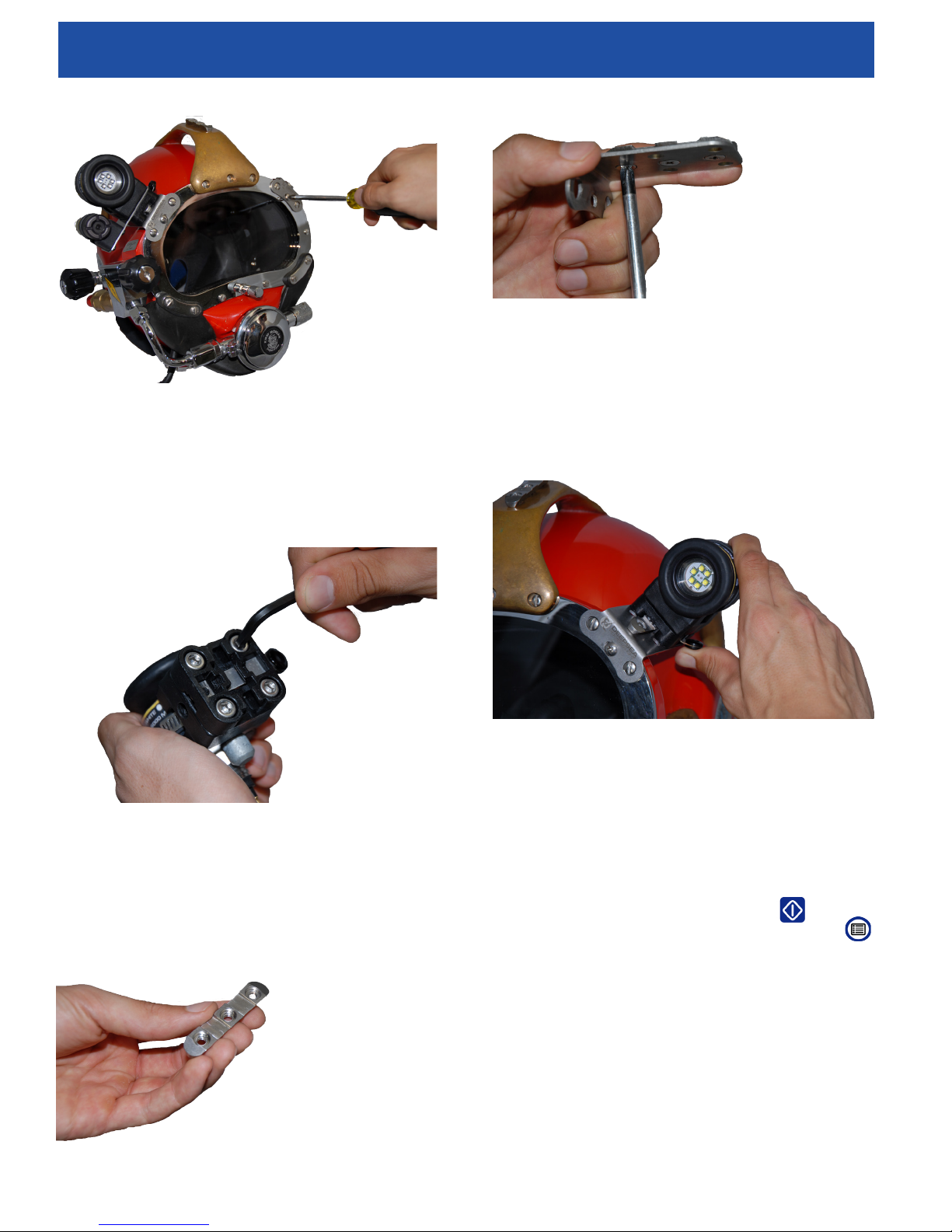
4. Attach the mounting brackets to a diver helmet.
Ensure proper faceplate torque specications are
met (See Figure 14).
13
Page 14
DVS-300
Diver Video System
Operator’s Manual
Item 2, Figure 16 - Quick Release to Helmet Brackets
Figure 14 - Mounting Brackets
5. Attach quick release mounts to LED lights and the
camera (See Figure 15).
Figure 15 - Quick Release Mount
7. Pull up on the quick release mechanism to slide
the light and camera assembly onto the mounted
foot. (See Figure 17)
Figure 17 - Quick Release Mechanism
Interface Overview
Navigating
6. Mount the metal rail dovetail (See Item 1, Figure
16) on helmet brackets (See Item 2, Figure 16).
Item 1, Figure 16
14
Use the arrow keys on the CCU-10 to navigate through
menus and screens. Use the Select Key to make
selections and to apply changes. Use the Menu Key
to move backwards through menus and screens, and to
cancel out of a menu.
Page 15
Operator’s Manual
DVS-300
Diver Video System
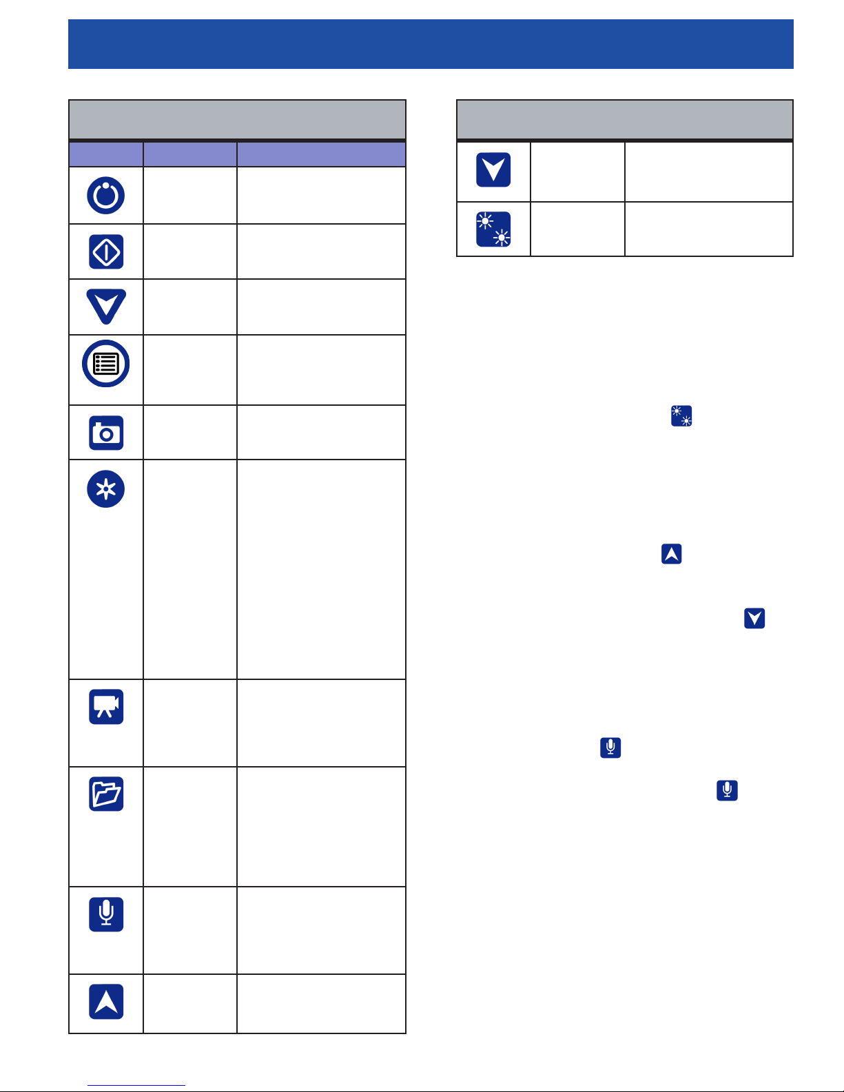
Table 5
CCU-10 Keys and Functions
Icon Name Function
Power Key Turns the CCU-10 ON or
OFF
Select Key Used to select menu
items.
Arrow Keys Used to navigate menus
and screens.
Menu Key Allows access to the
Settings, Display,
Language, and Media
Menus.
Photo Key Takes a photo.
Autolog Key Starts and stops Autolog
video recording. Autolog
videos are made up
of continuous audio
recording and still-image
frames taken at regular
intervals and saved in
a compressed format.
When an Autolog video
is recording, the LED
located on the bottom of
the Autolog Key will be
red
Video Key Starts and stops video
recording. When a video
is recording, the LED
located on the bottom of
the Video Key will be red.
Job Manager
Key
Microphone
Mute Key
LED Dimmer
Key
(Increase)
Opens a menu to allow
the manual ejection of
the thumb drive, the
manual creation of a
Report, and access to the
list of les on the thumb
drive for viewing
Toggles the microphone
ON or OFF. When
ON, the LED on the
Microphone Mute Key will
be gold in color.
Press to step up
brightness levels.
Table 5
CCU-10 Keys and Functions
LED Dimmer
Key
(Decrease)
Light Toggle
Switch
LED Toogle Switch Key
The LED Toggle Switch key allows you to toggle
between two LED lights connected to the system,
allowing adjustment and use of only one light or both
simultaneously. At minimum brightness the blue LED
next to the LED Toggle Switch Key will be OFF and
at maximum brightness the LED will be ON steadily. In
between, the LED will blink faster the brighter the setting.
In addition to the blinking LED, an indicator bar will appear
in the Status Overlay to visually represent the increasing
and decreasing LED brightness.
The Light Dimmer Increase button is used to brighten
the output of the lights when connected to the system.
When maximum brightness is achieved the CCU-10 will
give a tone. The light dimmer decrease button can
be used to dim the lights all the way to zero light output,
where the CCU-10 will give a tone.
Microphone Mute Key
When there is no external microphone input present, the
Microphone Mute Key is ON by default; meaning
that, the microphone is unmuted and audio is being
recorded. Press the Microphone Mute Key to mute
the audio when recording video or Autolog video. When
the Microphone Mute Key is pressed muting the audio in,
the LED on the main keypad will be off.
The internal Microphone is automatically switched off
whenever an external audio source is plugged in to the
“Audio In” jack in the rear of the CCU-10. In this case, the
Microphone Mute Key has no effect.
Screen
The on-screen interface has two regions: the Live View
Press to step down
brightness levels.
Toggles between the two
LED lights.
15
Page 16
DVS-300
!
Diver Video System
Operator’s Manual
and the Status Overlay.
Live View is the term for the largest area of the screen
where the live video feed appears.
During video or Autolog video recording and after taking a
photo, the Status Overlay will also include the percentage
of space remaining on the USB thumb drive plugged into
the USB port.
Operating Instructions
WARNING
Always wear eye protection to protect your
eyes against dirt and other foreign objects.
Do not operate this equipment if operator or
machine is standing in water. Operating the
DVS-300 while in water increases the risk of
electrical shock. Rubber soled non-slip shoes
can help prevent slipping and electric shock,
especially on wet surfaces.
Follow operating instructions to reduce the
risk of injury from electrical shock and other
causes.
Starting Up the DVS-300
Start the DVS-300 in accordance with the following:
Check that the unit is properly set up.
Connect the CCU-10 to a power source in conjunction
with the LED lights and the camera.
Mount the camera and lights as previously specied to a
Diver helmet or to the universal hand grip.
Press the Power Key to turn the DVS-300 lights and
camera ON.
After completing the start-up, the display will show a view
from the camera head. While the diver is underwater,
watch the screen to monitor the camera.
Jobs
The CCU-10 automatically saves photos, videos, and
Autolog videos to the latest folder on the thumb drive. The
CCU-10 will open a new job if there is not already one on
the thumb drive. The CCU-10 will save media les to a
new session on the thumb drive when the thumb drive is
ejected and when the CCU-10 shuts down.
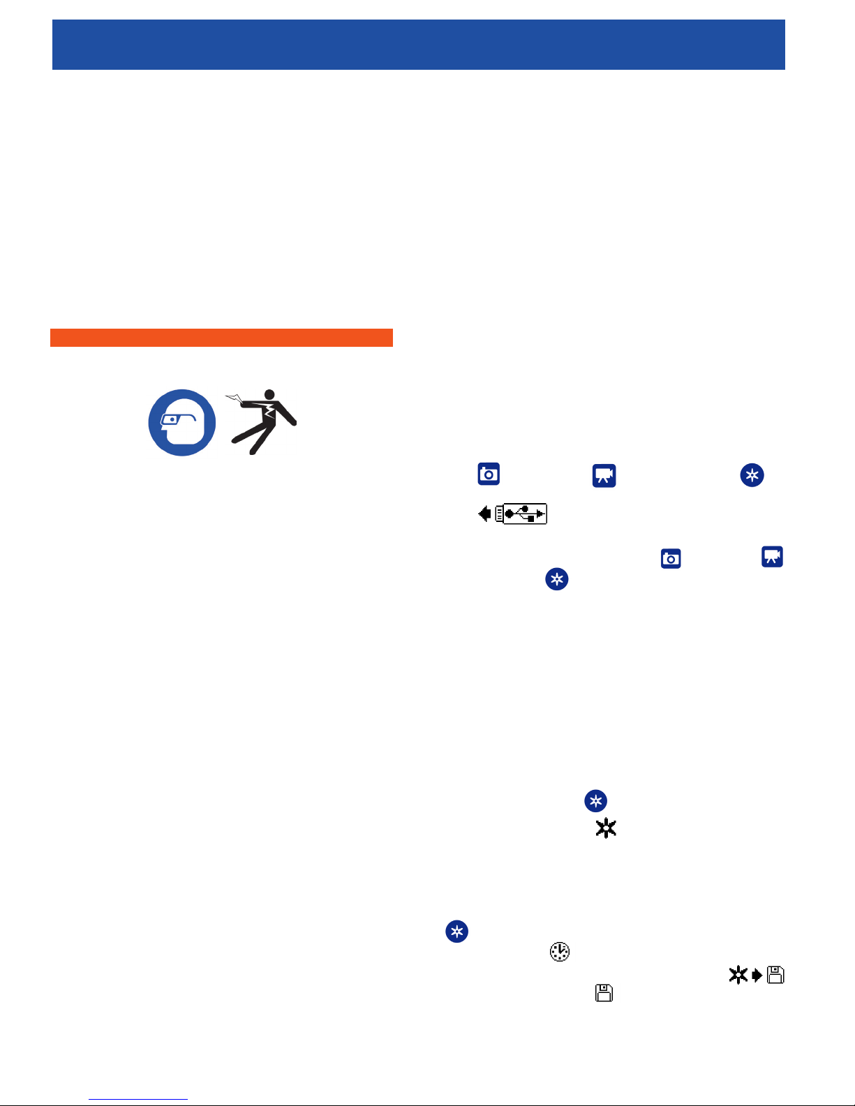
Although the CCU-10 will turn ON and enable viewing with
the camera, the CCU-10 cannot capture video, Autolog
video, or a photo until a thumb drive is inserted into the
USB port and the appropriate key has been pushed.
If a thumb drive is not in the USB port and if the Photo
Key ,Video Key ,or Autolog Key is
pressed, the CCU-10 will display the Insert Thumb Drive
Icon , the CCU-10 will beep, and the USB
LED will blink rapidly. After inserting a thumb drive into
the USB port, press the Photo Key ,Video Key
, or Autolog Key again to capture media.
Recording Autolog Video
Autolog video captures a highly compressed video of
an inspection, but uses a smaller le size than standard
video. An Autolog video recording saves screen images
in a motion JPEG (MJPEG) video format at the rate of
four frames per second. When the camera does not
move, the CCU-10 will stop adding new frames until the
camera moves again.
Press the Autolog Key to start recording an Autolog
video. The Autolog Icon will briey appear at the
start of each Autolog video recording. The Autolog LED
will also be lit during Autolog recording.
To stop the Autolog recording, press the Autolog Key
again. When the CCU-10 ends Autolog recording,
the Loading Icon appears. While saving the Autolog
le to the thumb drive, the Autolog Saving Icon
appears. The Saved Icon will appear when the CCU-
10 has successfully saved the Autolog le to the thumb
drive.
16
Page 17
Operator’s Manual
!
DVS-300
Diver Video System
The CCU-10 records audio continuously during an Autolog
video recording, regardless of camera movement. Press
the Microphone Mute Key to turn off the microphone
and to record an Autolog video without audio. When
muted, the LED on the Main Keypad will be OFF.
Press the Photo Key or the Video Key to
capture additional photos or higher frame rate video clips
while recording an Autolog video.
Recording HTML Video
Press the Video Key to start recording a video. The
Video Icon will appear briey at the start of a video
recording. The Video LED on the Main Keypad will also
be lit during video recording.
To stop video recording, press the Video Key again.
When the CCU-10 ends video recording, the Loading
Icon will appear. While saving the Video le to the
thumb drive, the Video Saving Icon will appear.
The Saved Icon will appear when the CCU-10 has
successfully saved the video le to the thumb drive.
The CCU-10 records audio continuously during a video
recording, regardless of camera movement. Press the
Microphone Mute Key to turn OFF the microphone
and to record a video without audio. When muted, the
LED on the Main Keypad will be OFF.
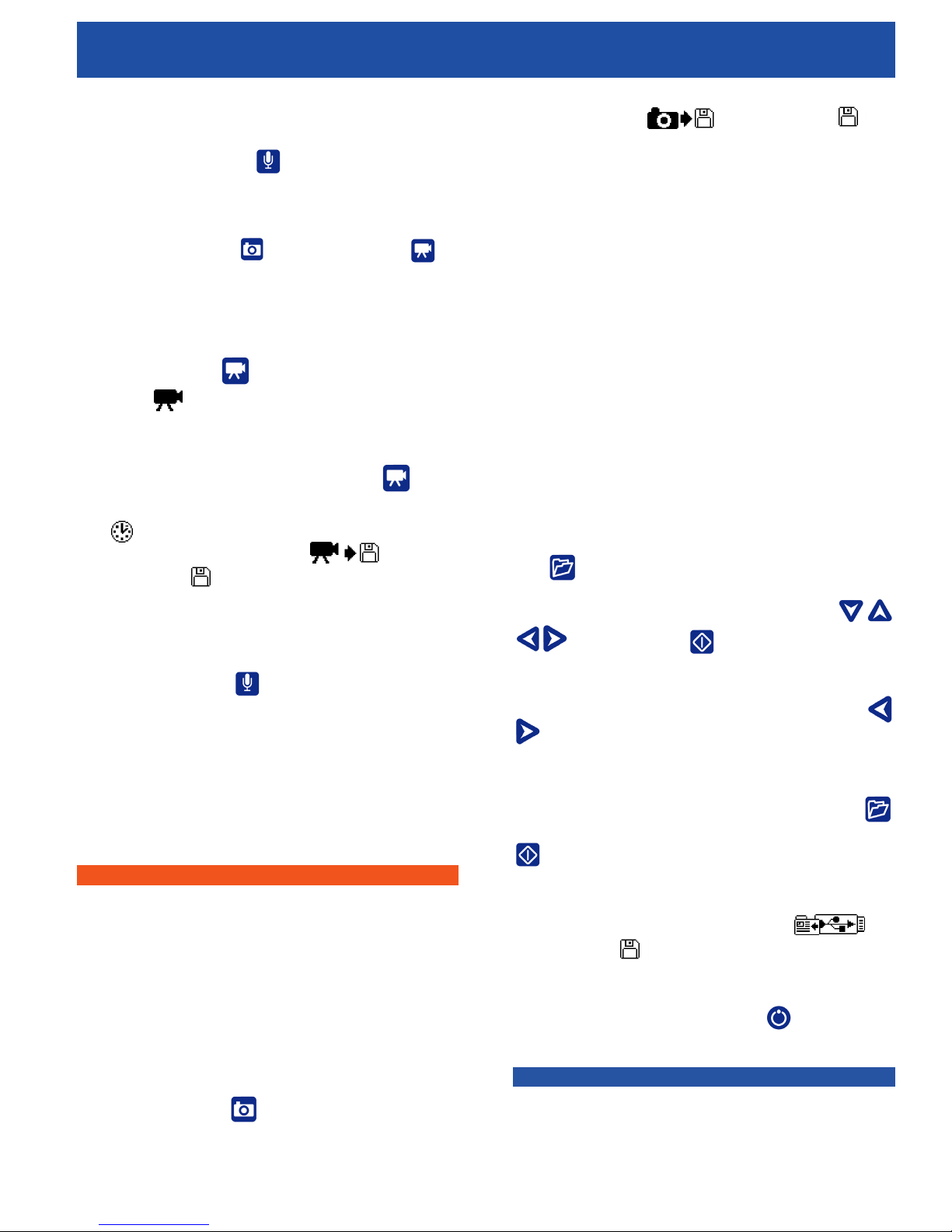
Photo Saving Icon . The Saved Icon will
appear to indicate that the photo has been saved to the
thumb drive. Photos can be taken during video recording.
Annotating an Inspection by Voice
When the microphone is ON (unmuted), the LED on the
Main Keypad will be gold. Mute the microphone at any
point during a video or Autolog video recording to turn the
sound OFF during portions of the video and to eliminate
unwanted sounds from becoming part of the Report.
If diver audio input is required, insert the communication
system into the rear of the CCU-10 and connect via the
Audio In jack. This will switch the internal microphone
OFF until the audio device is unplugged.
Reviewing Images and Video
To review the photo, video, and Autolog video les
stored on the USB thumb drive press the Job Manager
Key and select “Media List.” Alternatively, access
the Job Manager screen from the Main Menu . From
the Job Manager screen, use the Arrow Keys
and Select Key to navigate between and
select media les saved on the USB thumb drive. Video
and Autolog video recordings can be fast forwarded and
rewound by using the Right and Left Arrow Keys
.
Video and Autolog video can be recorded simultaneously
and independent of each other. Both video recording
types can be started and stopped without affecting the
other.
WARNING
WARNING: The DVS-300 is only capable of
recording in 4 Gigabyte increments so be sure
to monitor the CCU-10 to ensure the device
is still recording. If planning to record more,
start recording again like previous as soon as
the 4 Gigabyte maximum has been reached.
Taking Photos
Press the Photo Key to take a photo. The Status
Overlay will appear for 3seconds after the photo has been
taken. While saving the photo, the CCU-10 will display the
Completing a Dive
After completing a Dive, press the Job Manager Key
. Navigate to the “Eject USB” and press the Select Key
to close the Job before shutting down the CCU-10.
By default, closing the current Job will make a Report so
that images and video can be viewed in any web browser.
After closing the Job, the Job Saving Icon and
the Saved Icon will appear to indicate that the Jobs
have been successfully saved. The USB LED will turn
OFF when the thumb drive may be safely removed from
the USB port. Press the Power Key to power OFF
the DVS-300.
NOTICE
NOTE: Do not remove the USB thumb drive until the
USB LED has turned OFF.
17
Page 18
DVS-300
Diver Video System
Operator’s Manual
If media has been captured and if the thumb drive
has been incorrectly removed, CCU-10 will beep, the
message, “Unsafe USB Removal” will appear in the top
left hand corner of the screen, and one of the following
will occur:
● If the CCU-10 has been set to automatically
create a Report upon ejection of the thumb drive,
press the Select Key to clear the message
and insert the thumb drive back into the USB port
when prompted by the message, “Insert USB
” to create a Report.
● If the CCU-10 has been set to manually create
a Report upon ejection of the thumb drive, only
the beep will be heard. Press the Select Key
to clear the message and to return to the main
screen.
See the section on Report creating preferences for
more information.
Adjusting Settings
Press the Menu Key to access the Settings Menu,
the Display Menu, the Language Menu, and the Media
Menu to make changes to the following:
date display. Use the up and down Arrow Keys
to navigate to “time/date” from the Main menu and the
Select Key to choose it. Use the left and right Arrow
Keys to scroll between the various elds. Fields that can
be edited will have a blinking red outline.
To change the time and date format between 12 hour to
24 hour and between MM/DD/YYYY to DD/MM/YYYY,
either use the up and down Arrow Keys or push
the Select Key within the highlighted eld. To exit the
menu after changing the settings, press the Menu Key
.
Adjusting Video Format
From the Settings Menu, choose from either MJPEG or
MPEG4 video formats. Use the left and right Arrow Keys
or press the Select Key to toggle between
the video format options.
Adjusting Language Preference
From the Language Menu, use Up and Down Arrow Keys
to select a new language and press the Select
Key to choose it.
Adjusting Report Creating Preferences
● Monitor color, contrast and brightness
● Time/date
● Video format
● Language preference
● Report creating preferences
Adjusting Monitor Settings
From the Display Menu make changes to the monitor
color, monitor contrast, and monitor brightness. Use the
Up and Down Arrow Keys to navigate to the
setting you want to adjust and the Select Key to choose
it. Then use the Arrow Keys to increase
or decrease the selected settings preference levels. View
the increasing and decreasing settings on the slider bar
below the menu. To exit the menu after changing the
settings, press the Menu Key .
Adjusting Time and Date Format
From the Settings Menu change the format of the time/
The CCU-10 offers two Report creating options: Auto and
Manual. From the Settings Menu, press the Select Key
to toggle between “Auto” and “Manual.”
When “Auto” is selected, the CCU-10 will automatically
create a Report after media is captured and after the
thumb drive is ejected from the USB port. By default, the
CCU-10 will be set to “Auto.”
When “Manual” is selected, the CCU-10 will not create
a Report if the thumb drive is ejected. Press the Job
Manager Key and select “Make a Report” to manually
create a Report.
Delivering Reports by USB Thumb Drive
To deliver a Report, access the Media Menu by either
pressing the Job Manager Key or by pressing the
Main Menu Key . From the Media Menu, select “Make
Report”.
18
Page 19
Operator’s Manual
DVS-300
Diver Video System
Alternatively, if the CCU-10 has been set to automatically
create a Report, a Report will be created if “Eject USB” is
selected from the Media Menu.
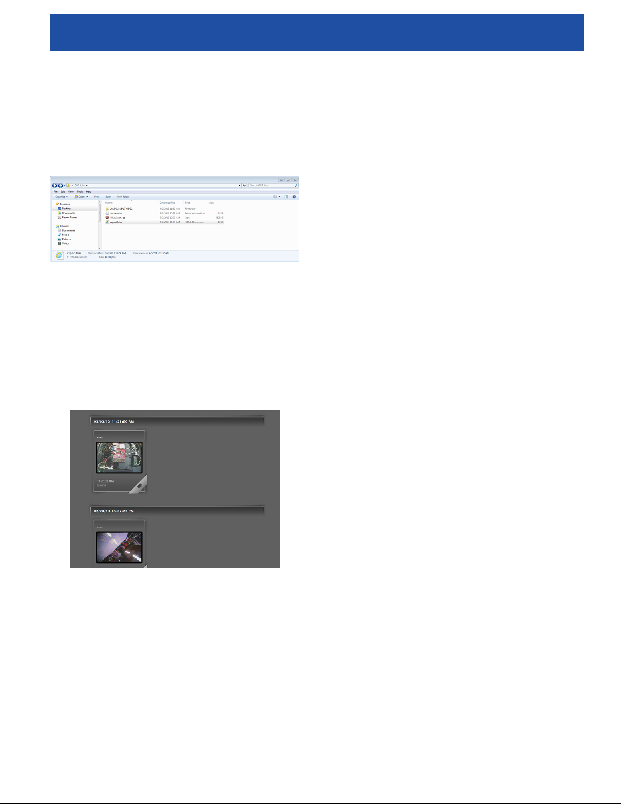
Insert the thumb drive into a USB port on a computer to
view the list of les (See Figure 18).
Figure 18 - Thumb Drive
Double-click the le named “report.html” to view the media
in a web browser (See Figure 18). An internet connection
is not necessary to view the “report.html” le. Click on
the preview of each media item in the web browser to
view full size photos and to playback video and Autolog
video. Use the browser’s “back” button to return to the
initial page.
allow any liquid to enter the CCU-10.
Accessories
The following accessories have been designed
for use with the DVS-300. Other accessories may
become hazardous when used with the DVS-300. To
reduce the risk of serious injury, only use accessories
specically designed and recommended for use with
the DVS-300.
● DeepSea UV lighting solution
● DeepSea quick release brackets
● DeepSea quick release helmet mounts
● DeepSea Universal hand grip
Transport and Storage
Keep the equipment indoors or well-covered in wet
weather. Store the DVS-300 in a locked area, out of the
reach of children and people unfamiliar with its operation.
This equipment could cause serious injury in the hands
of untrained users. Do not expose to heavy shocks or
impacts during transport.
Figure 19 - View of Media
Maintenance Instructions
Cleaning
Disconnect all cords and cables and remove batteries
prior to cleaning the CCU-10 to reduce the risk of electrical
shock.
Do not use liquid or abrasive cleaners on the CCU-10.
Clean the CCU-10 with damp cloth. Only clean screen
with cleaners approved for use on LCD screens. Do not
Remove batteries before shipping and before storing for
extended periods.
Store electrical devices in a dry place to reduce risk of
electrical shock. Store in temperatures from 14°F to
158°F [−10°C to 70°C]. Store the unit away from heat
sources such as radiators, heat registers, stoves, and
other products (including ampliers) that produce heat.
Service and Repair
Please have your product model number, serial
number and any other pertinent information along
with a description of the problem, at hand when you
call, or include them in a fax or email. When shipping
your item, be sure that the freight is pre-paid (CODs
will not be accepted) and that the RMA number is
clearly printed on the outside of the box.
19
Page 20

DVS-300
Diver Video System
Operator’s Manual
Phone: 858-576-1261 ext. 324
Fax: 858-576-0219
Email: [email protected]
Warranty
Seller warrants that the goods (except internal electronic
components) sold under this contract will be free from
defect in material and workmanship for a period of one
year from the date of shipment from the factory, if they
have been properly used. Internal electronic components
are warranted for 90 days from the date of shipment from
the factory, if they have been properly used. This warranty
will be limited to the repair or replacement of parts and
the necessary labor and services required to repair
the goods. IT IS EXPRESSLY AGREED THAT THIS
WARRANTY WILL BE IN LIEU OF ALL WARRANTIES
OF FITNESS AND IN LIEU OF THE WARRANTY OF
MERCHANTABILITY. This warranty is the exclusive
and only warranty to pass with the goods under this
contract. No agent, employee, or representative of the
Seller has any authority to bind Seller to any information,
representation, or warranty concerning the goods
sold under this contract, and unless an afrmation,
representation, or warranty made by an agent, employee,
or representative is specically included within this
contract, it will not be enforceable by Buyer. If notice of
defect is given to DeepSea Power & Light, Inc. within such
90 day or one year warranty period, the sole obligation of
DeepSea Power & Light, Inc. shall be to furnish new or
repaired parts free of charge in exchange for parts which
have been proved defective and does not include any
other costs such as the cost of removal of the defective
part, installation, labor, or consequential damages of any
kind, the exclusive remedy being to require DeepSea
Power & Light, Inc. to furnish such new parts. Under no
circumstances shall the Buyer be entitled to recover any
incidental damages as that term is dened in Commercial
Code §2715.
Disposal
Parts of the unit contain valuable materials that can be
recycled. There are companies that specialize in recycling
that may be found locally. Dispose of the components in
compliance with all applicable regulations. Contact your
local waste management authority for more information.
For EC countries: Do not dispose of electrical equipment
with household waste!
According to the European Guideline 2002/96/EC
for Waste Electrical and Electronic Equipment and
its implementation into national legislation, electrical
equipment that is no longer usable must be collected
separately and disposed of in an environmentally-correct
manner.
Battery Disposal
Return used batteries to a collection location for recycling.
Call 800 822 8837 or visit www.call2recycle.org to nd a
collection location.
For EC countries: Defective or used battery packs/
batteries must be recycled according to the guideline
2006/66/EC.
Only these rows apply, still need to talk to engineering for
additional troubleshooting
Troubleshooting
Troubleshooting Scenerios
Problem Problem Fault Solution
Camera video
image not seen.
Flashing battery
warning appears
Low battery
buzzer sounds
or both battery
LEDs turn red
SOS blinking on
Power Key LED
No power to
camera
Connections
faulty
18 V Li-Ion
batteries low
18 V Li-Ion
batteries low
18 V Li-Ion
batteries low
No Video signal Reset
Check power
to correctly
plugged in.
Check
alignment and
pinout from
CCU-10 to the
Diver Cable.
Recharge
batteries. Switch
to AC power.
Recharge
batteries. Switch
to AC power.
Recharge
batteries. Switch
to AC power.
driver cable
connection.
20
Page 21

Operator’s Manual
DVS-300
Diver Video System
NOTES
21
Page 22

DVS-300
Diver Video System
Operator’s Manual
DEEPSEA
POWER & LIGHT
www.deepsea.com
[email protected]
22
4033 Rufn Road
San Diego, CA
92123- 1817 USA
®
T: (858) 576-1261
F: (858) 576-0219
 Loading...