

Deep Sea Electronics Plc DSE7310 MKII, DSE7320 MKII Installation Instructions And Operators Manual

TYPICAL WIRING DIAGRAM
NOTE: Terminals 38, 39, 40 & 41 are not fitted to the DSE7310 MKII.
NOTE: A larger version of the Typical Wiring Diagram is available in the product’s operator manual, refer to
DSE Publication: 057-253 DSE7310 MKII & DSE7320 MKII Operator Manual available from www.deepseaplc.com for more
information.
Deep Sea Electronics Plc.
Tel:+44 (0)1723 890099
Fax: +44 (0)1723 893303
Email: support@deepseaplc.com
Web: www.deepseaplc.com
Deep Sea Electronics Inc.
Tel: +1 (815) 316 8706
Fax: +1 (815) 316 8708
Email: support@deepseausa.com
Web: www.deepseausa.com
DEEP SEA ELECTRONICS
DSE7310 MKII & DSE7320 MKII
Installation Instructions
053-181
ISSUE 4
ACCESSING THE MAIN CONFIGURATION EDITOR
• Ensure the engine is at rest and the module is in STOP mode by pressing the
(Stop/Reset) button.
• Press the (Stop/Reset) and (Tick) buttons simultaneously.
•
If a module security PIN has been set, the PIN number request is then shown:
• The first ‘#’ changes to ‘0’. Press the (Up) or (Down) button to adjust it to the correct value.
• Press the (Right) button when the first digit is correctly entered. The digit previously entered now shows ‘#’ for security.
• Repeat this process for the other digits of the PIN number. Press the (Left) button to move back to adjust one of the previous
digits.
•
When the (Tick) button is pressed after editing the final PIN digit, the PIN is checked for validity. If the number is not correct,
the PIN must be re-entered.
•
If the PIN has been successfully entered (or the module PIN has not been enabled), the editor is
displayed:
EDITING A PARAMETER
• Enter the editor as described above.
• Press the (Right) or (Left) buttons to cycle to the section to view/change.
• Press the (Up) or (Down) buttons to select the parameter to view/change within the currently selected section.
• To edit the parameter, press the (Tick) button to enter edit mode. The parameter begins to flash to indicate editing.
• Press the (Up) or (Down) buttons to change the parameter to the required value.
• Press the (Tick) button to save the value. The parameter ceases flashing to indicate that it has been saved.
• To exit the editor and save the changes, press and hold the (Tick) button.
• To exit the editor and not save the changes, press and hold the (Stop/Reset) button
.
NOTE: If the editor is left inactive for the duration of the LCD Page Timer, it is automatically exited to ensure security.
NOTE: The PIN number is automatically reset when the editor is exited (manually or automatically) to ensure security.
NOTE: Comprehensive module configuration is possible using the DSE Configuration Suite PC Software, refer to DSE
publication 057-243 DSE7310 MKII & DSE7320 MKII Configuraiton Suite PC Software Manual available from
www.deepseaplc.com.
DSE7310 MKII & DSE7320 MKII
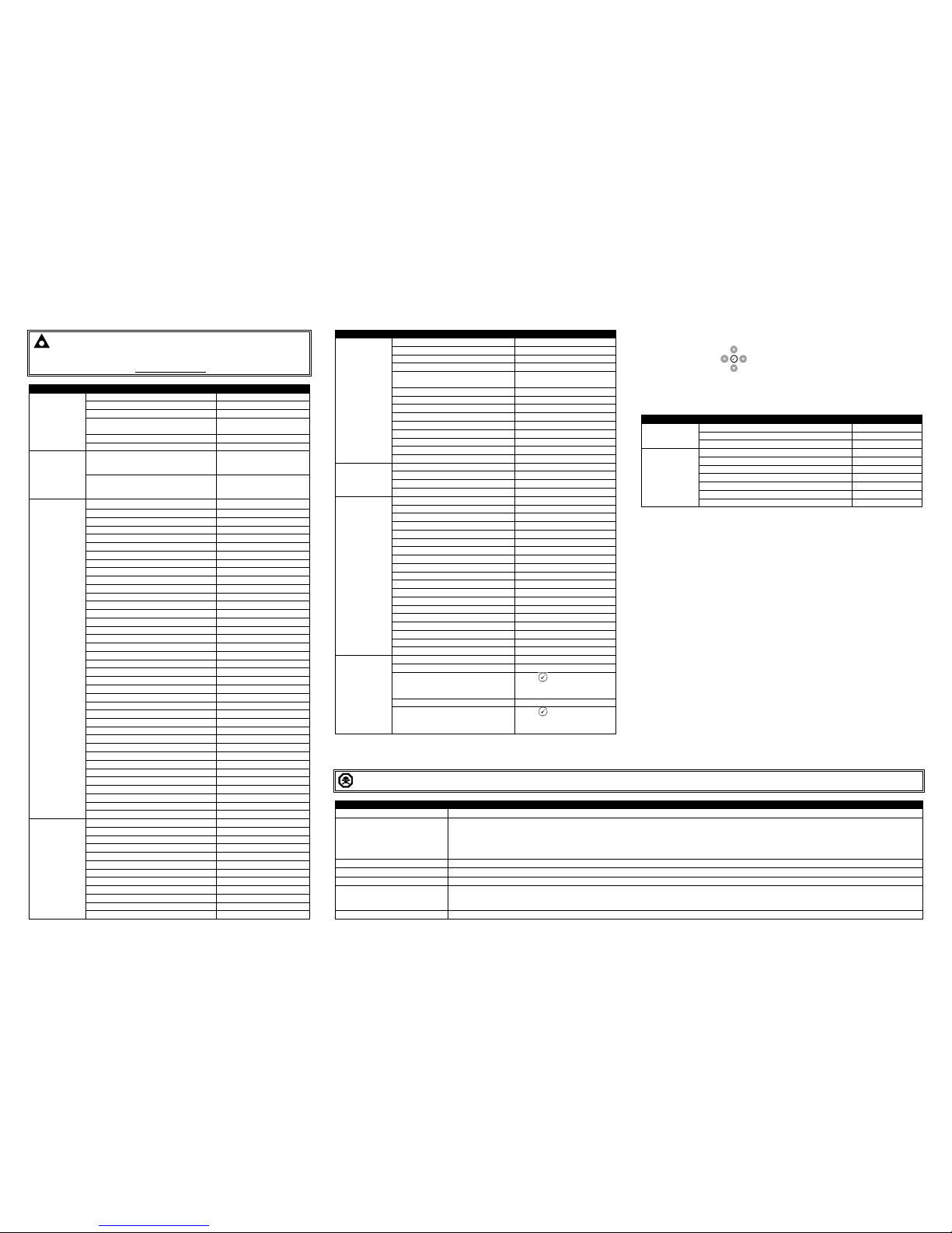
MAIN CONFIGURATION EDITOR PARAMETERS
NOTE: Depending upon module configuration, some values in the Main &
Running Configuration Editors may not be available. For more information refer to
DSE publication 057-243 DSE7310 MKII & DSE7320 MKII Configuraiton Suite PC
Software Manual available from www.deepseaplc.com
Section Parameter As Shown On Display
Value
Display
Contrast 0 %
Language English
Current Date and Time Month, Year, hh:mm
Dual Mutual Mode
Engine Hours / Dual Mutual
Hours / Priority
Dual Mutual Priority 0
Dual Mutual Duty Time 0 h 0 m
Editor
Config To Edit
Main Configuration /
Alternative Configuration
1,2,3,4,5
Default Configuration
Main Configuration /
Alternative Configuration
1,2,3,4,5
Engine
Oil Pressure Low Shutdown 0.00 bar
Oil Pressure Low Pre Alarm 0.00 bar
Coolant Temperature Low Warning 0 ºC
Coolant Temperature High Pre Alarm 0 ºC
Coolant Temperature High Electrical Trip 0 ºC
Coolant Temperature High Shutdown 0 ºC
Fuel Usage Alarm (Running Rate) 0 %
Fuel Usage Alarm (Stopped Rate) 0 %
Specific Gravity 0.00
Pre Heat Temperature 0 ºC
Post Heat Timer 0 h 0 m 0 s
Pre Heat Timer 0 h 0 m 0 s
Post Heat Temperature 0 ºC
Droop Control Active / Inactive
Droop Control 0 %
Engine Under Speed Shutdown Active / Inactive
Engine Under Speed Shutdown 0 RPM
Engine Under Speed Warning Active / Inactive
Engine Under Speed Warning 0 RPM
Engine Under Speed Delay 0.0 s
Engine Over Speed Warning Active / Inactive
Engine Over Speed Warning 0 RPM
Engine Over Speed Shutdown 0 RPM
Engine Over Speed Delay 0.0 s
Engine Speed Overshoot 0 %
Engine Speed Overshoot Delay 0.0 s
Battery Under Voltage Warning Active / Inactive
Battery Under Voltage Warning 0 V
Battery Under Voltage Warning Delay 0 h 0 m 0 s
Battery Over Voltage Warning Active / Inactive
Battery Over Voltage Warning 0 V
Battery Over Voltage Warning Delay 0 h 0 m 0 s
Charge Alternator Failure Warning Active / Inactive
Charge Alternator Failure Warning 0 V
Charge Alternator Warning Delay 0 h 0 m 0 s
Charge Alternator Failure Shutdown Active / Inactive
Charge Alternator Failure Shutdown 0.0 V
Charge Alternator Shutdown Delay 0 h 0 m 0 s
Generator
AC System 3 Phase, 4 Wire
Generator Under Voltage Shutdown 0 V
Generator Under Voltage Pre Alarm 0 V
Generator Under Voltage Delay 0.0 s
Generator Nominal Voltage 0 V
Generator Over Voltage Pre Alarm 0 V
Generator Over Voltage Shutdown 0 V
Generator Over Voltage Delay 0.0 s
Generator Under Frequency Shutdown 0.0 Hz
Generator Under Frequency Pre Alarm 0.0 Hz
Generator Under Frequency Delay 0.0 s
Generator Nominal Frequency 0.0 Hz
MAIN CONFIGURATION EDITOR PARAMETERS (CONTINUED)
Section Parameter As Shown On Display
Value
Generator
Generator Over Frequency Pre Alarm 0.0 Hz
(Continued)
Generator Over Frequency Shutdown 0.0 Hz
Generator Under Frequency Delay 0.0 s
Generator Over Frequency Overshoot 0 %
Generator Over Frequency Overshoot
Delay
0.0 s
Generator CT Primary Current 0 A
Generator Secondary Current 1 A / 5 A
Generator CT Primary Earth Current 0 A
Full Load Rating 0 A
Delayed Over Current Active / Inactive
Delayed Over Current 0 %
Generator Earth Fault Trip Active / Inactive
Generator Earth Fault Trip 0 %
kW Overload Trip 0 %
Mains
Mains Under Voltage Trip 0 V
DSE7320 MKII
Mains Over Voltage Trip 0 V
Only
Mains Under Frequency Trip 0.0 Hz
Mains Over Frequency Trip 0.0 Hz
Timers
Start Delay Off Load 0 h 0 m 0 s
Start Delay On Load 0 h 0 m 0 s
Start Delay Mains Fail 0 h 0 m 0 s
Start Delay Telemetry 0 h 0 m 0 s
Mains Transient Delay 0 m 0 s
Crank Duration Timer 0 m 0 s
Crank Rest Timer 0 m 0 s
Smoke Limiting 0 m 0 s
Smoke Limiting Off 0 m 0 s
Safety On Delay 0 m 0 s
Warm Up Timer 0 h 0 m 0 s
Transfer Time 0 m 0.0 s
Return Delay 0 h 0 m 0 s
Cool Down Timer 0 h 0 m 0 s
Fail To Stop Delay 0 m 0 s
LCD Page Timer 0 h 0 m 0 s
Auto Scroll Delay 0 h 0 m 0 s
Sleep Timer 0 h 0 m 0 s
Backlight Power Save 0 h 0 m 0 s
Schedule
Schedule Active / Inactive
Schedule Bank 1 Period Weekly / Monthly,
On Load / Off Load / Auto Start Inhibit,
Week, Start Time, Run Time and Day
Selection (1-8)
Press to begin editing then
up or down when selecting the
different parameters.
Schedule Bank 2 Period Weekly / Monthly,
On Load / Off Load / Auto Start Inhibit,
Week, Start Time, Run Time and Day
Selection (1-8)
Press to begin editing then
up or down when selecting the
different parameters.
ACCESSING THE ‘RUNNING’ CONFIGURATION EDITOR
• The ‘running’ editor can be entered while the engine is running. All protections remain
active if the engine is running while the running editor is entered.
• Press and hold the (Tick) button to enter the running editor.
RUNNING CONFIGURATION EDITOR PARAMETERS
Section Parameter As Shown On Display
Values
Display
Contrast 0 %
Language English
Dual Mutual
Dual Mutual Priority 0
Engine
Manual Frequency Trim 0.0 Hz
Speed Bias 0.0
Governor Gain 0
Frequency Adjust 0.0 %
DPF Auto Regen Inhibit Active / Inactive
DPF Manual Regeneration Request Active / Inactive
ECU Service Mode Active / Inactive
DIMENSIONS AND MOUNTING
DIMENSIONS
245 mm X 184 mm X 51 mm
(9.6” X 7.2” X 2.0”)
PANEL CUTOUT
220 mm X 160 mm
(8.7” X 6.3”)
WEIGHT
0.98 kg
(2.16 lb)
TEMPERATURE
Operating: -40 ºC to +70 ºC
(-40 ºF to +158 ºF)
Storage: -40 ºC to +80 ºC
(-40 ºF to +176 ºF)
RE
QUIREMENTS FOR UL CERTIFICATION
WARNING!: More than one live circuit exists, see diagram overleaf for further information.
Specification
Description
Screw Terminal Tightening Torque
•
4.5 lb-in (0.5 Nm)
Conductors
•
Terminals suitable for connection of conductor size 13 AWG to 20 AWG (0.5 mm² to 2.5 mm²).
• Conductor protection must be provided in accordance with NFPA 70, Article 240
• Low voltage circuits (35 V or less) must be supplied from the engine starting battery or an isolated secondary circuit.
• The communication, sensor, and/or battery derived circuit conductors shall be separated and secured to maintain at least ¼” (6 mm) separation from the
generator and mains connected circuit conductors unless all conductors are rated 600 V or greater.
Current Inputs
•
Must be connected through UL Listed or Recognized isolating current transformers with the secondary rating of 5 A max.
Communication Circuits
•
Must be connected to communication circuits of UL Listed equipment
DC Output Pilot Duty
•
0.5 A
Mounting
•
Suitable for flat surface mounting in Type 1 Enclosure Type rating with surrounding air temperature -22 ºF to +122 ºF (-30 ºC to +50 ºC)
• Suitable for pollution degree 3 environments when voltage sensing inputs do not exceed 300 V. When used to monitor voltages over 300 V device to be
installed in an unventilated or filtered ventilation enclosure to maintain a pollution degree 2 environment.
Operating Temperature
•
-22 ºF to +122 ºF (-30 ºC to +50 ºC)
 Loading...