

Config’ Section Parameter Type Icons displayed
Analogue senders
Low Pressure Trip
Low Pressure Pre Alarm
High Temperature Pre Alarm
High Temperature Trip
Fuel Level % Pre Alarm
Calendar Date/time Date/time
Timers
Mains transient delay Timer (secs)
1
Start delay Timer (secs)
2
Preheat Timer (secs)
3
Crank attempt Timer (secs)
4
Crank rest Timer (secs)
5
Safety delay Timer (secs)
6
Overspeed overshoot Timer (secs)
7
Warming up Timer (secs)
8
Transfer delay Timer (secs)
9
Return delay Timer (secs)
10
Cooling run Timer (secs)
11
E.T.S.(Energise to stop) solenoid hold Timer (secs)
12
Mains (utility) supply
Mains Low Voltage Trip
V
Mains High Voltage Trip
V
Mains Low Frequency Trip
Mains High Frequency Trip
Generator output
Generator Under Voltage L1-N Trip
V
Generator Under Voltage L1-N Pre Alarm
V
Generator Over Voltage Pre Alarm
V
Generator Over Voltage Trip
V
Generator Under Frequency Trip
Generator Under Frequency Pre Alarm
Generator Over Frequency Pre Alarm
Generator Over Frequency Trip
Delayed Overcurrent % Trip
A
Engine speed
Under Speed (RPM) Trip
Under Speed (RPM) Pre Alarm
Over Speed (RPM) Pre Alarm
Over Speed (RPM) Trip
DC Voltages
Low DC Voltage Warning
V
High DC Voltage Warning
V
Charge Alternator Failure Warning
DEEP SEA ELECTRONICS
Model 5220 Installation and Configuration Instructions
Accessing the front panel config’ editor
Press the configure/log and Stop/Reset buttons simultaneously.
The LCD configure indicator
# will flash to indicate that the module is in ‘configuration mode’. Release the
Stop/Reset button and the configure/log button.
If a PIN number has been set, press + / - to set the first digit, then press 9 to adjust the next
digit.
Repeat this until all four digits have been entered.
The first configurable parameter is now displayed. Pressing the + or - buttons will cycle through the
parameters.
NOTE:- To exit the front panel configuration editor at any time, press the Stop/Reset
button. Ensure you have saved any changes yo u have made by pressing the 9 button first.
Editing an analogue value
Access the front panel config editor as detailed above. Press the +/- buttons to view the parameter you
wish to change (see parameter table overleaf). Press the 9 button to enter adjust mode. The value to be
adjusted will flash. Press the +/- buttons to adjust the parameter to the desired value. Press the 9 button
to ‘save’ the value. The value will stop flashing to confirm that it has been saved. To select another value to
edit, press the + button. Continuing to press the +/- buttons will cycle through the available parameters.
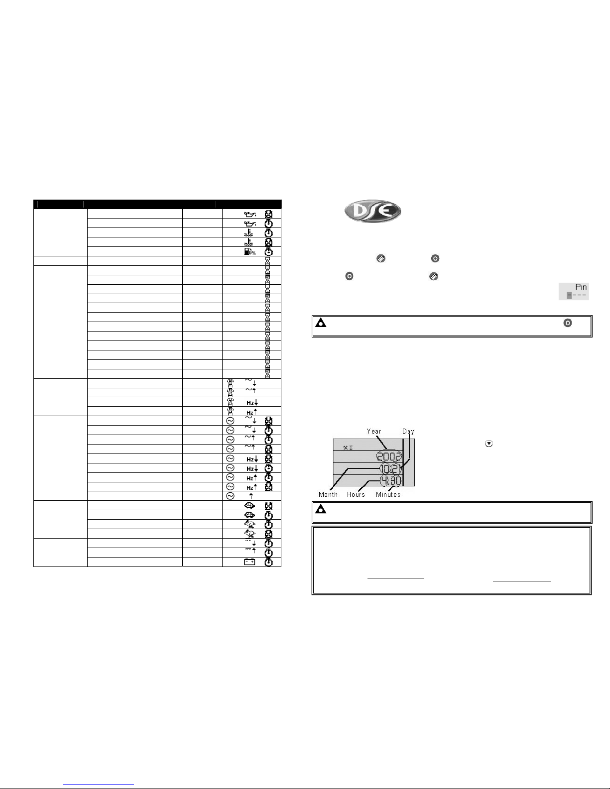
Editing the time
The date/time should initially be set using the 5200 series configuration software. However there may be
certain circumstances where a minor change to the module’s time is required. One such instance is
correction for daylight saving. Access the front panel config editor as detailed above. Press the + button
until the calendar is shown :
To edit the time, press the 9 button. The minutes, ‘30’ in this
example, will begin flashing. Press the + or - buttons to adjust
the minutes. Press the
button to select hours, day, month
and year. The selected parameter will flash.
Press the 9 button to save the change. The time stops flashing
to confirm that it has been successfully stored.
Example : This display is showing a time of 4:30 on 21st
October 2002.
NOTE:- Full configuration of the 5220 module is possible using the 5200 series confi guration
software for PC in conjunction with the P 810 interface.
Deep Sea Electronics Plc.
Highfield House, Hunmanby Industrial Estate,
North Yorkshire. YO14 0PH. ENGLAND.
Tel:+44 (0)1723 890099
Fax: +44 (0)1723 893303.
Email: sales@deepseaplc.com
Web: www.deepseaplc.com
LO CALL (from UK BT landlines) : Telephone
0845 260 8900.
Deep Sea Electronics Inc.
3230 Williams Avenue, Rockford,
IL 61101-2668, USA
Phone: +1 (815) 316-8706
Fax: +1 (815) 316-8708
Email: dsesales@deepseausa.com
Web: www.deepseausa.com
TOLL FREE (USA only) Tel: 1 866 636 9703
053-020 ISSUE 4
http://bestgenerator.spb.ru/?page_id=6765
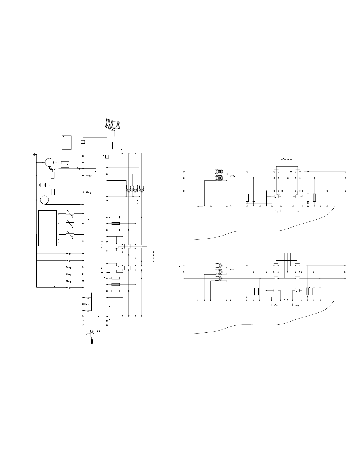
To plant supply +ve
Crank
Starter
motor
Battery
Charge
alt.
WL
F F
Fuel
Emergency
stop
internal emergency stop
Configurable auxiliary input 1
Configurable a u x ilia ry input 2
Configurable auxiliary input 3
Configurable auxiliary input 4
Configurable auxiliary input 5
L1
L2
L3
N
F2A F2A F2A
+
Supply for
controller
These ground connections must be
on the engine block and must be
a sound electrical connection
to the sender bodies.
The ground wire to terminal 47 must
not be used to provide a ground
connection to any other device.
Coolant temp. sender
Fuel level sender
RS485
Optional
9 way D
Optional
RS232
5220 controller
Optional
CanBus
Not connected
Output expansion
157 relay board
or
548 annunciator
5200 series
configuration software
810 interface
810
157/548
Ground screen
at one end only
Functional
Earth
MPU
17
18
16
6 7 8
1413
12
1110
474645
Oil pressure sender
449
4
531 2
39 40 41 42
43
CT
common
CT
Earth
35
36 37 38
20 21 22
23
24
25
26
Configurable auxiliary input 6
15
Configurable auxiliary output 1
Configurable auxiliary output 2
Configurable auxiliary output 3
SCR A
B
COM H
L
Not connected
F2A F2A F2A
31
32 33 34
G M
LOAD
Mechanical interlock
Electrical interlock
Generator Mains (utility)
19
Not connected
28273029
Generator
loading
relay
Mains
loading
relay
L1
L2
L3
N
Dimensions
Module Dimensions - 240mm x 172mm x 57mm (9.45” x 6.77” x 2¼”)
Panel cutout - 220mm x 160mm ( 8.7” x 6.3”)
Alternative AC wiring
2 phase, 3 wire ( 2 phase centre tap neutral)
L1
L2
N
F2A F2A
39 40 41 42 43
CT
common
CT
Earth
35
36 37 38
Not connected
F2A F2A
31
32 33 34
G M
LOAD
Mechanical interlock
Electrical interl ock
Generator Mains (utility)
28273029
Generator
loading
relay
Mains
loading
relay
L1
L2
N
3 phase, 3 wire
L1
L2
L3
F2A F2A F2A
39 40 41 42
43
CT
common
CT
Earth
35 36 37
38
Not connected
F2A F2A F2A
31
32 33
34
G M
LOAD
Mechanical interlock
Electrical interlock
Generator
Mains (utility)
28273029
Generator
loading
relay
Mains
loading
relay
L1
L2
L3
Not connected
Not connected
T
yp
ical Wiring Diagram
http://bestgenerator.spb.ru/?page_id=6765
 Loading...