

Page 1

USB-TTL-32 / USB-TTL-64
Hardware-Description
2011
November
Page 2
INDEX
1. Introduction 6
1.1. General remarks 6
1.2. Customer satisfaction 6
1.3. Customer response 6
2. Hardware description 8
2.1. Introduction 8
2.2. Quick installation 9
2.2.1. Step 1 - Installation of the software and driver
2.2.2. Step 2 - Connecting of the module
2.2.3. Step 3 - Testing the connection and the module
2.3. Technical data 10
2.4. Overview screens 11
2.4.1. Overview screen USB-TTL-32
2.4.2. Overview screen USB-TTL-64
11
12
2.5. Block diagram 13
2.5.1. Block diagram USB-TTL-32
2.5.2. Block diagram USB-TTL-64
13
14
2.6. Configuration of the voltage level of TTL-I/O's 15
2.7. Pin assignment 16
2.7.1. J1 - Pin assignment USB-TTL-I/O 0-31
2.7.2. J2 - Pin assignment USB-TTL-I/O 32-63
16
17
3. Software 19
9
9
9
3.1. Using our products 19
3.1.1. Access via graphical applications
3.1.2. Access via the DELIB driver library
3.1.3. Access via protocol
3.1.4. Access via provided test programs
19
19
19
20
Index | 2Seite
Page 3
INDEX
3.2. DELIB driver library 21
3.2.1. Overview
3.2.1.1. Program under diverse operating systems
3.2.1.2. Program with diverse programming languages
3.2.1.3. Program independent of the interface
3.2.1.4. SDK-Kit for Programmer
3.2.2. Supported operating systems
3.2.3. Supported programming languages
3.2.4. Installation DELIB driver library
3.2.5. DELIB Configuration Utility
21
21
22
22
22
23
23
24
28
3.3. Test programs 29
3.3.1. Digital Input-Output Demo
29
4. DELIB API reference 31
4.1. Management functions 31
4.1.1. DapiOpenModule
4.1.2. DapiCloseModule
4.1.3. DapiGetDELIBVersion
4.1.4. DapiSpecialCMDGetModuleConfig
4.2. Error handling 36
31
32
33
34
4.2.1. DapiGetLastError
4.2.2. DapiGetLastErrorText
36
37
4.3. Set TTL-In-/Outputs direction 38
4.3.1. DAPI_SPECIAL_CMD_SET_DIR_DX_8
38
4.4. Reading Digital inputs 39
4.4.1. DapiDIGet1
4.4.2. DapiDIGet8
4.4.3. DapiDIGet16
4.4.4. DapiDIGet32
4.4.5. DapiDIGet64
4.4.6. DapiDIGetFF32
4.4.7. DapiDIGetCounter
39
40
41
42
43
44
45
4.5. Setting Digital outputs 46
Index | 3Seite
Page 4
INDEX
4.5.1. DapiDOSet1
4.5.2. DapiDOSet8
4.5.3. DapiDOSet16
4.5.4. DapiDOSet32
4.5.5. DapiDOSet64
4.5.6. DapiDOReadback32
4.5.7. DapiDOReadback64
46
47
48
49
50
51
52
4.6. Example program 53
5. Appendix 57
5.1. Revisions 57
5.2. Copyrights and trademarks 58
Index | 4Seite
Page 5
Introduction
I
Introduction |Seite 5
Page 6
1. Introduction
1.1. General remarks
First of all, we would like to congratulate you to the purchase of a high quality
DEDITEC product.
Our products are being developed by our engineers according to quality
requirements of high standard. Already during design and development we take
care that our products have -besides quality- a long availability and an optimal
flexibility.
Modular design
The modular design of our products reduces the time and the cost of development.
Therefor we can offer you high quality products at a competitive price.
Availability
Because of the modular design of our products, we have to redesign only a module
instead of the whole product, in case a specific component is no longer available.
1.2. Customer satisfaction
Our philosophy: a content customer will come again. Therefor customer
satisfaction is in first place for us.
If by any chance, you are not content with the performance of our product, please
contact us by phone or mail immediately.
We take care of the problem.
1.3. Customer response
Our best products are co-developments together with our customers. Therefor we
are thankful for comments and suggestions.
Introduction |Seite 6
Page 7
Hardware description
II
Hardware description |Seite 7
Page 8
2. Hardware description
2.1. Introduction
The USB-OPTOIN-X-RELAIS-X modules provide relays with a maximum switching
voltage of 36V DC (max. 1A, 15 watts) and Opto-in inputs, which are suitable for
industrial applications for registration of status or even to count the changes of
state of the inputs.
Our USB modules have been developed for industrial applications for
measurement, control and regulation. The modules all feature a USB interface and
can therefore be connected to PC systems with USB bus. The USB bus has been
used successfully for many years in use and is characterized by its high flexibility.
As terminal block, user-friendly terminal strips with locking protection and ejection
mechanism are used. They allow quick replugging . The wire connection itself is
realised with a screwless connector system. A tool is included with each module.
Hardware description |Seite 8
Page 9
2.2. Quick installation
2.2.1. Step 1 - Installation of the software and driver
Now install the driver DELIB library with the file "delib_install.exe" from the supplied
DEDITEC-Driver CD.
These can be found in the "\zip\DELIB\delib_install.exe" on the DEDITEC-Driver
CD.
Note: On our website www.deditec.de you can always find the latest DELIB driver
version.
2.2.2. Step 2 - Connecting of the module
Connect your PC via USB cable to the USB connector of the module.
After about 20 seconds, the module is detected by the driver and can now be
tested and operated.
2.2.3. Step 3 - Testing the connection and the module
In the Start menu, see "Start -> All Programs -> DEDITEC -> DELIB -> Sample
Programs" you will find some example programs to test your module.
Hardware description |Seite 9
Page 10
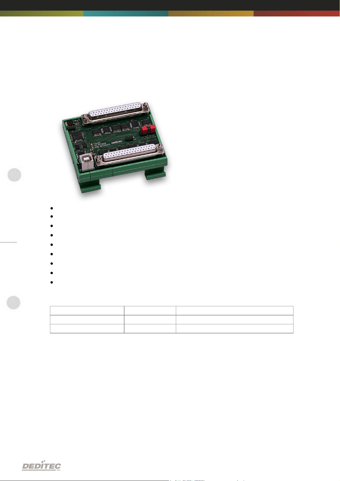
2.3. Technical data
Product
TTL-I/O's
Connectors
USB-TTL-32
32
1*37 pin D-sub connector
USB-TTL-64
64
2*37 pin D-sub connector
USB-Interface (USB 1.1 / USB 2.0)
5V from the USB bus
TTL Pegel 5V to 1,3V
TTL-I/O (in 8-way blocks adjustable as input or output)
Activity-LED Power (Indicates that the module is in operation)
IO-Access (Indicates the access to the TTL-I/O)
USB-Activity (Indicates that a signal processing via the USB bus is taking place)
Operating temperature 10°C..+50°C
Dimensions 90 mm x 77 mm x 42 mm (L x W x H)
Product specific data:
Hardware description |Seite 10
Page 11
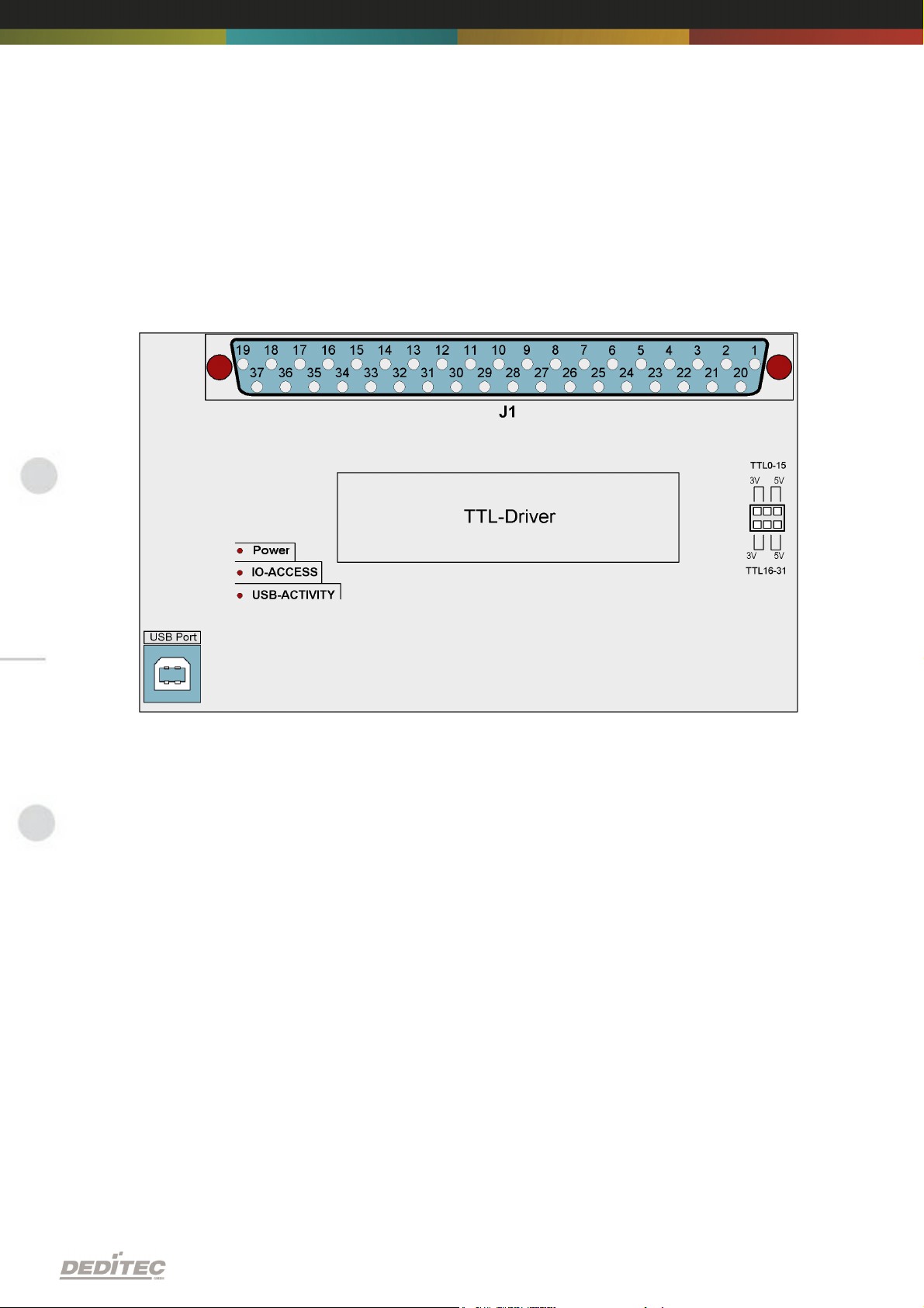
2.4. Overview screens
2.4.1. Overview screen USB-TTL-32
Hardware description |Seite 11
Page 12
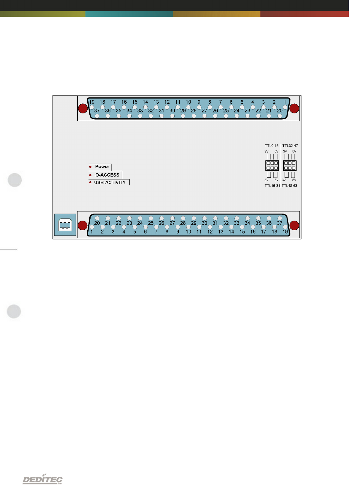
2.4.2. Overview screen USB-TTL-64
Hardware description |Seite 12
Page 13
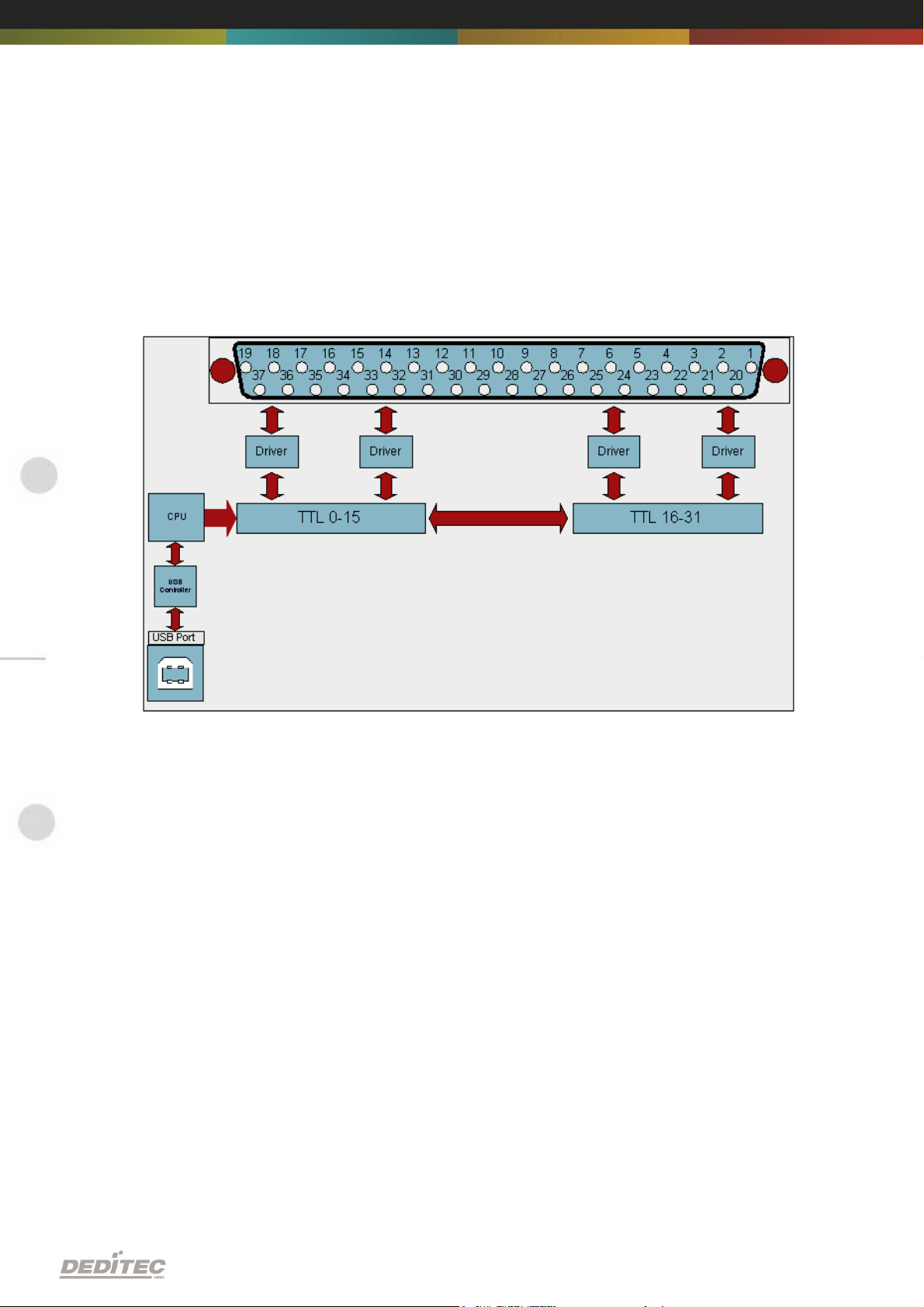
2.5. Block diagram
2.5.1. Block diagram USB-TTL-32
Hardware description |Seite 13
Page 14
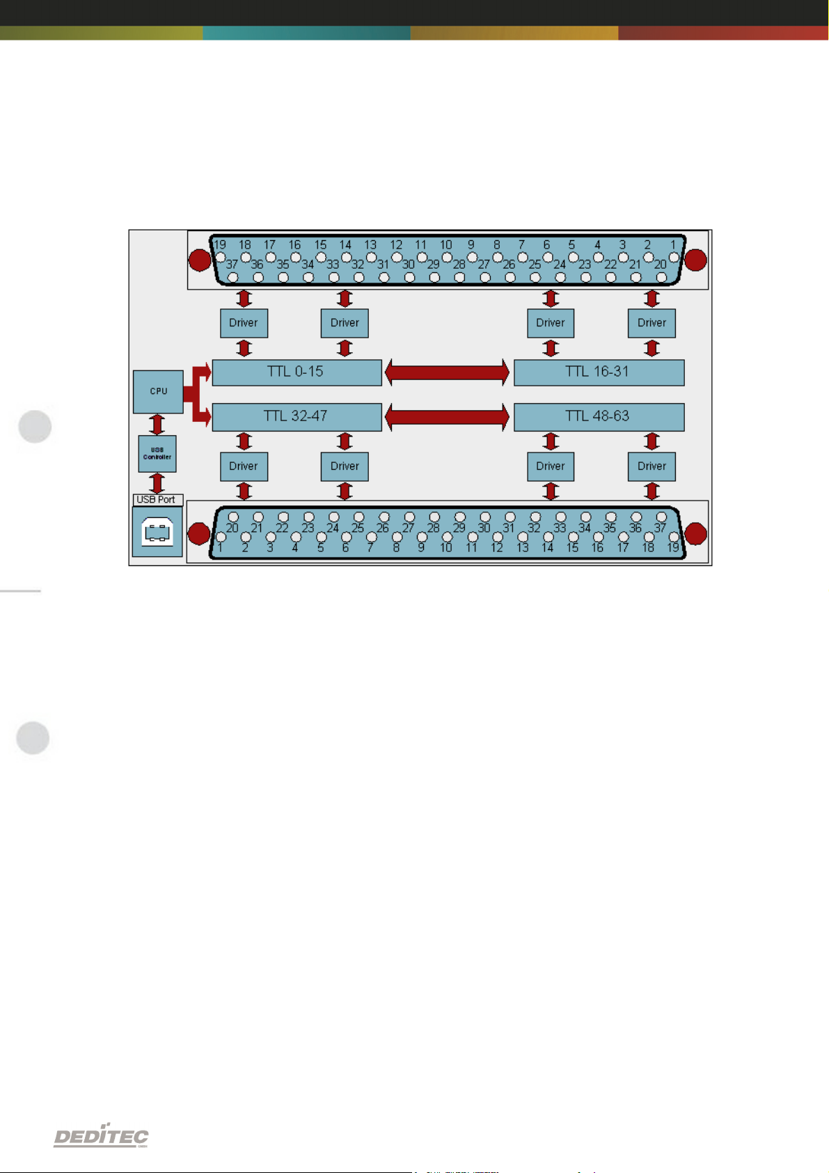
2.5.2. Block diagram USB-TTL-64
Hardware description |Seite 14
Page 15
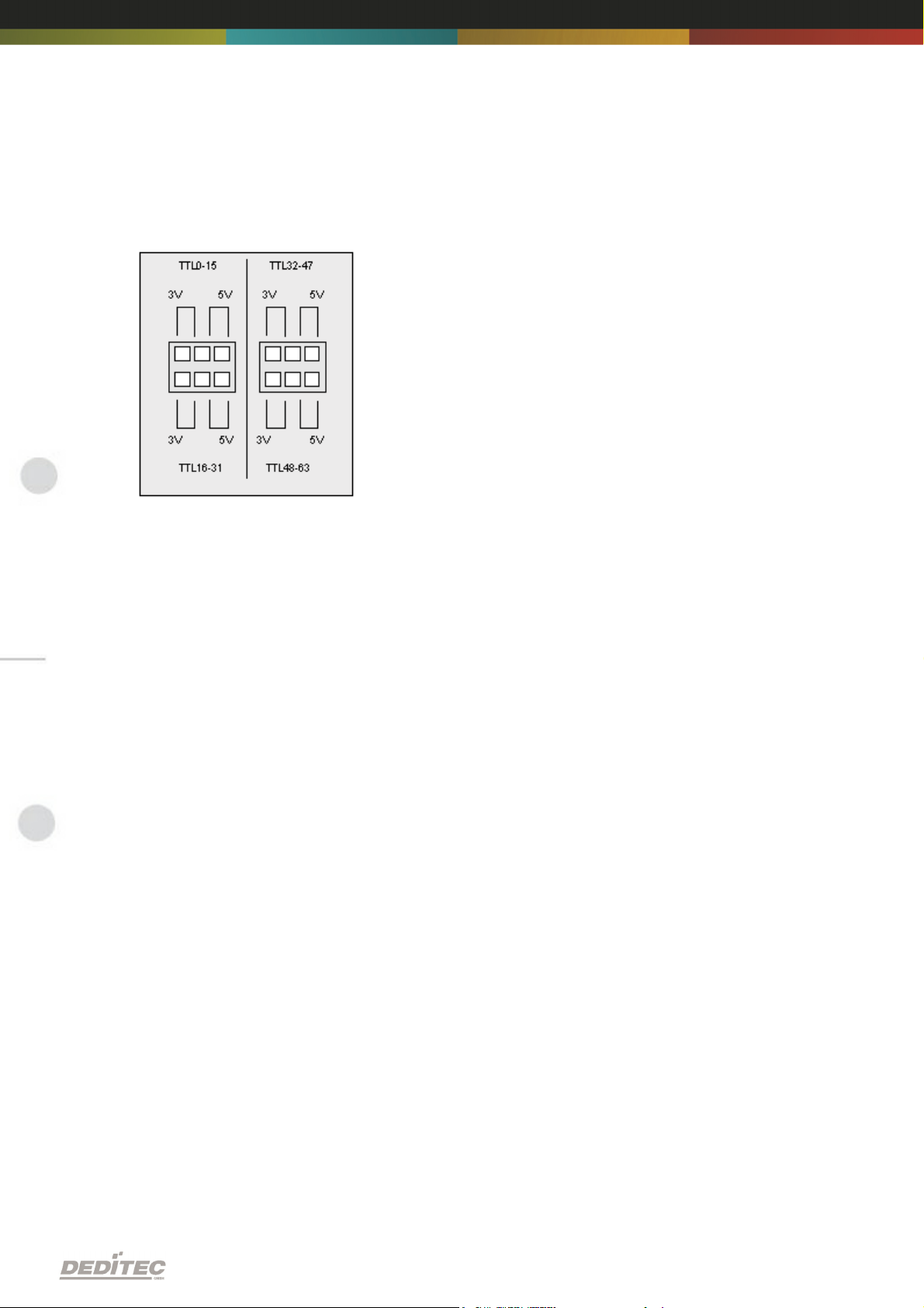
2.6. Configuration of the voltage level of TTL-I/O's
TTL level of 1.8 V to 5 V:
By default, you can select the TTL level of 3.3 V or 5V via jumper.
If you remove the jumper on the module, you can apply your own voltage between
1.8 V to 5 V to the TTL-I/O module, so the possibilities of the modules were
significantly increased.
If you want to apply your own voltage, this is done via the VIN pin see chapter Pin
assignment.
The TTL-I/O's of the module can be configured in a 16 blocks.
Hardware description |Seite 15
Page 16
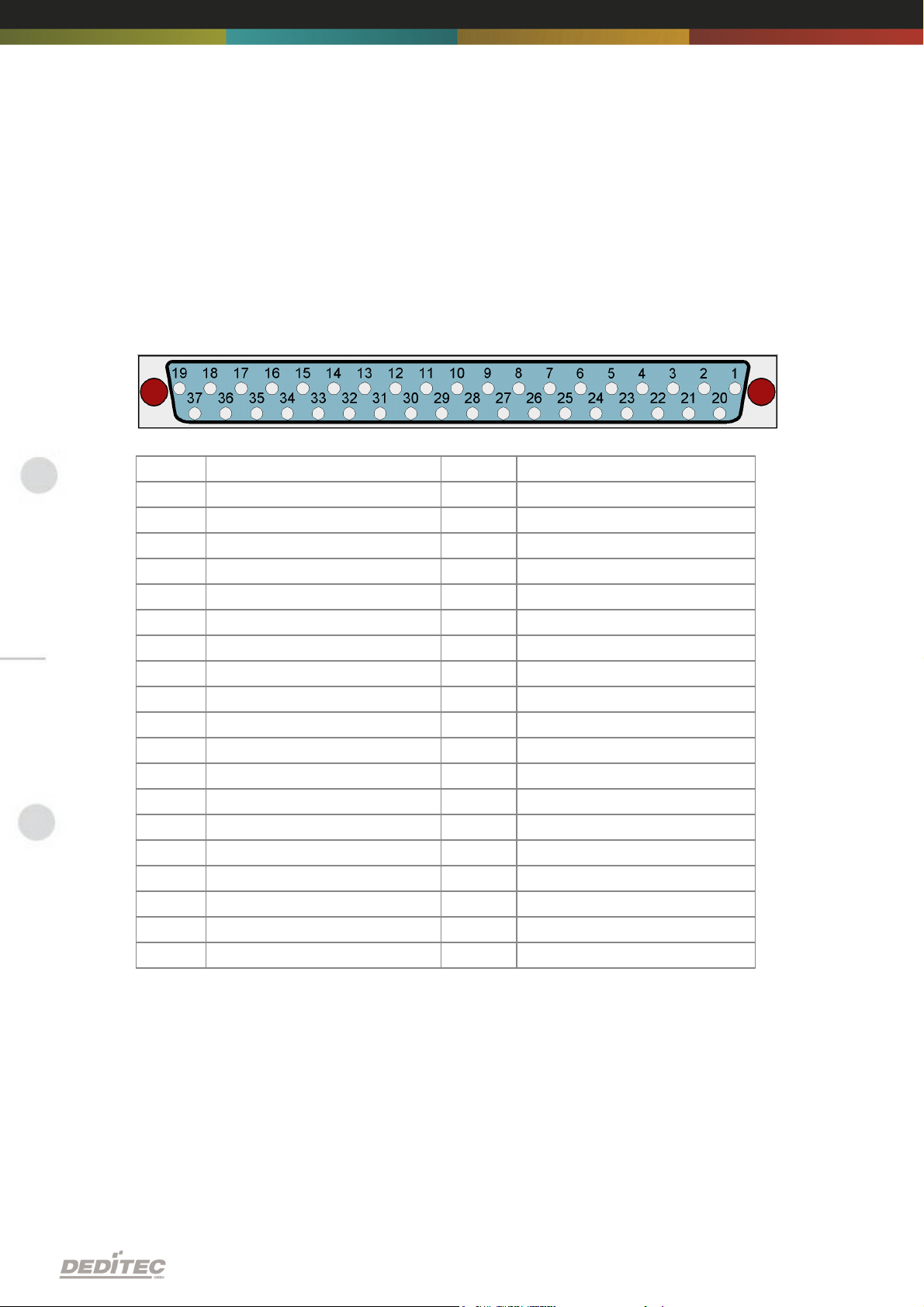
2.7. Pin assignment
Port
Pin
Port
Pin1I/O 16
20
I/O 17
2
I/O 18
21
I/O 19
3
I/O 20
22
I/O 21
4
I/O 22
23
I/O 23
5
I/O 24
24
I/O 25
6
I/O 26
25
I/O 27
7
I/O 28
26
I/O 29
8
I/O 30
27
I/O 31
9
I/O 0
28
I/O 1
10
I/O 2
29
I/O 3
11
I/O 4
30
I/O 5
12
I/O 6
31
I/O 7
13
I/O 8
32
I/O 9
14
I/O 10
33
I/O 11
15
I/O 12
34
I/O 13
16
I/O 14
35
I/O 15
17
VIN 0-15
36
VIN 16-31
18
GND
37
GND
19
GND
2.7.1. J1 - Pin assignment USB-TTL-I/O 0-31
Note: The VIN pin is used to apply your own voltage to the I/O's of the module. This
voltage can be between 1.8V and 5V.
Hardware description |Seite 16
Page 17
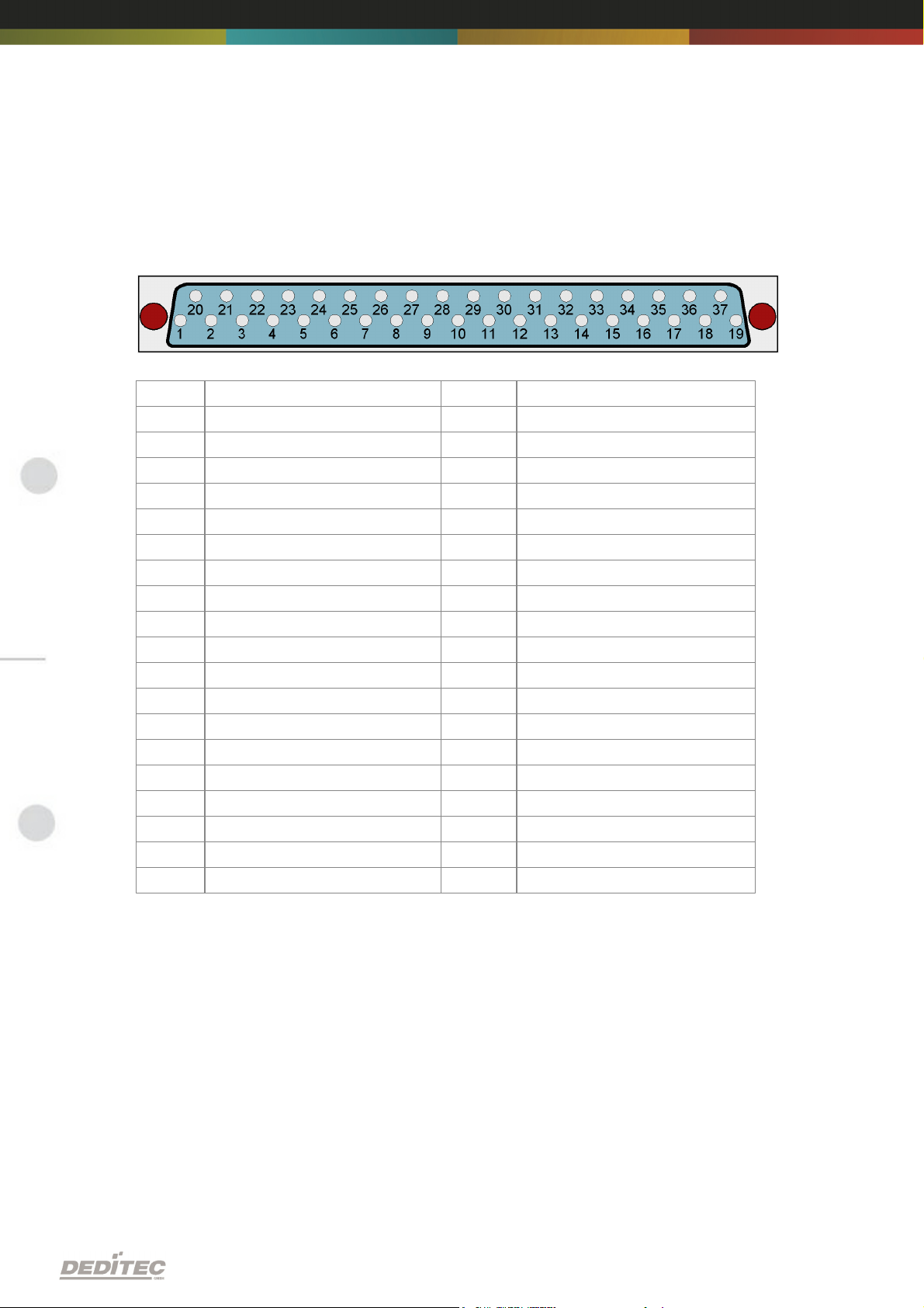
2.7.2. J2 - Pin assignment USB-TTL-I/O 32-63
Port
Pin
Port
Pin1I/O 48
20
I/O 49
2
I/O 50
21
I/O 51
3
I/O 52
22
I/O 53
4
I/O 54
23
I/O 55
5
I/O 56
24
I/O 57
6
I/O 58
25
I/O 59
7
I/O 60
26
I/O 61
8
I/O 62
27
I/O 63
9
I/O 32
28
I/O 33
10
I/O 34
29
I/O 35
11
I/O 36
30
I/O 37
12
I/O 38
31
I/O 39
13
I/O 40
32
I/O 41
14
I/O 42
33
I/O 43
15
I/O 44
34
I/O 45
16
I/O 46
35
I/O 47
17
VIN 32-47
36
VIN 48-63
18
GND
37
GND
19
GND
Note: The VIN pin is used to apply your own voltage to the I/O's of the module. This
voltage can be between 1.8V and 5V.
Hardware description |Seite 17
Page 18
Software
III
Software |Seite 18
Page 19
3. Software
3.1. Using our products
3.1.1. Access via graphical applications
We provide driverinterfaces e.g. for LabVIEW and ProfiLab. The DELIB driver
library is the basis, which can be directly activated by ProfiLAB.
For LabVIEW, we provide a simple driver connection with examples!
3.1.2. Access via the DELIB driver library
In the appendix, you can find the complete function reference for the integration of
our API-functions in your software. In addition we provide examples for the
following programming languages:
C
C++
C#
Delphi
VisualBasic
VB.NET
MS-Office
3.1.3. Access via protocol
The protocol for the activation of our products is open source. So you are able to
use our products on systems without Windows or Linux.
Software |Seite 19
Page 20
3.1.4. Access via provided test programs
We provide simple handling test programs for the most important functions of our
products. These will be installed automatically by the installation of the DELIB
driver library.
So you can test directly e.g. relays or you can check the voltage of an A/D
converter.
Software |Seite 20
Page 21
3.2. DELIB driver library
3.2.1. Overview
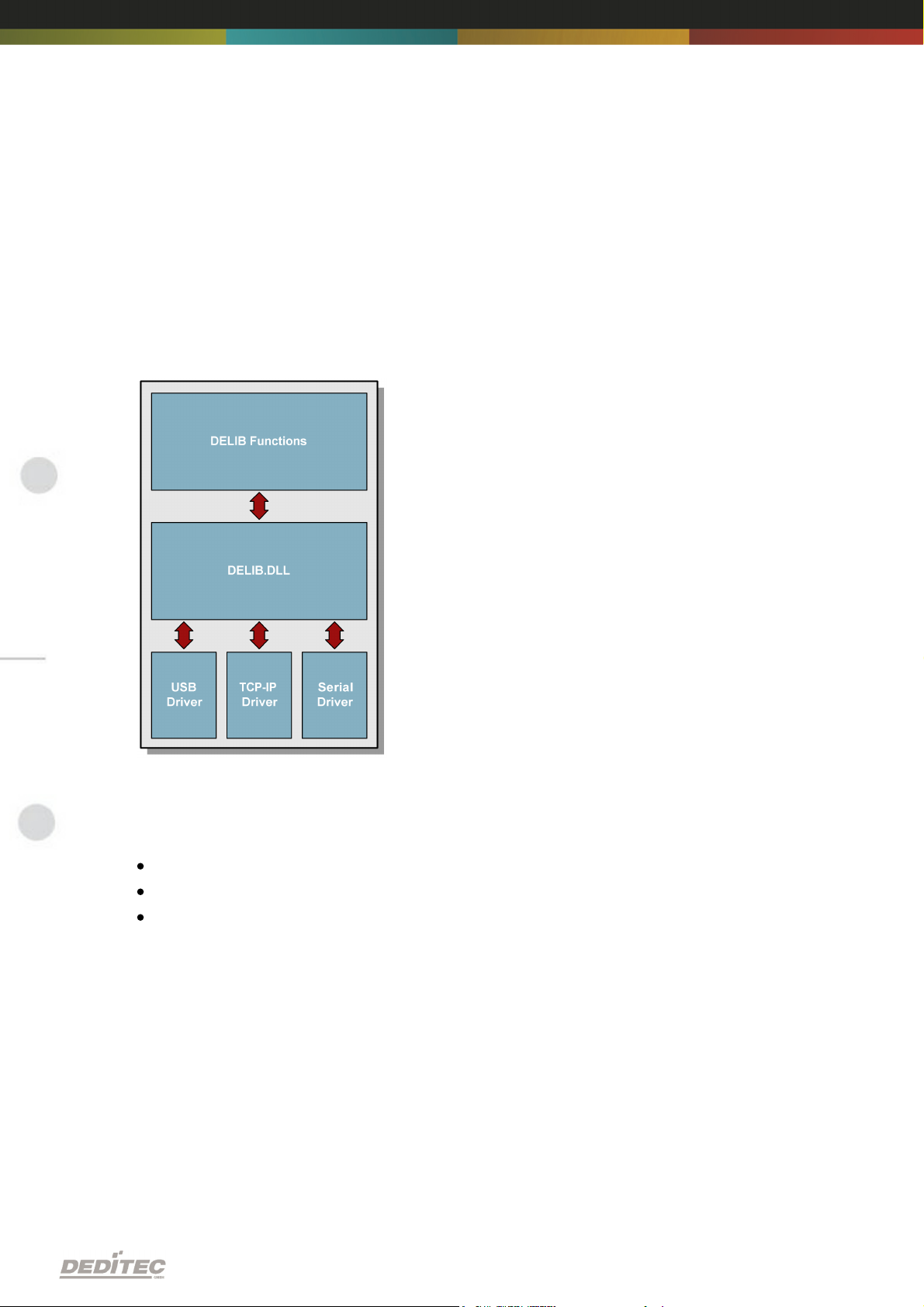
The following figure explains the structure of the DELIB driver library
The DELIB driver library allows an uniform response of DEDITEC hardware with
particular consideration of the following viewpoints:
Independent of operating system
Independent of programming language
Independent of the product
3.2.1.1. Program under diverse operating systems
The DELIB driver library allows an uniform response of our products on diverse
operating systems.
We has made sure, that all of our products can be responded by a few commands.
Whatever which operating system you use. - Therefore the DELIB cares!
Software |Seite 21
Page 22
3.2.1.2. Program with diverse programming languages
We provide uniform commands to create own applications. This will be solved by
the DELIB driver library.
You choose the programming language!
It can be simply developed applications under C++, C, Visual Basic, Delphi or
LabVIEW®.
3.2.1.3. Program independent of the interface
Write your application independent of the interface !
Program an application for an USB product of us. - Also, it will work with an
ethernet or RS-232 product of us !
3.2.1.4. SDK-Kit for Programmer
Integrate the DELIB in your application. On demand you receive an installation
script for free, which allows you, to integrate the DELIB installation in your
application.
Software |Seite 22
Page 23
3.2.2. Supported operating systems
Our products support the following operating systems:
Windows 7
Windows Vista
Windows XP
Windows 2000
Linux
3.2.3. Supported programming languages
Our products are responsive via the following programming languages:
C
C++
C#
Delphi
VisualBasic
VB.NET
MS-Office
Software |Seite 23
Page 24
3.2.4. Installation DELIB driver library
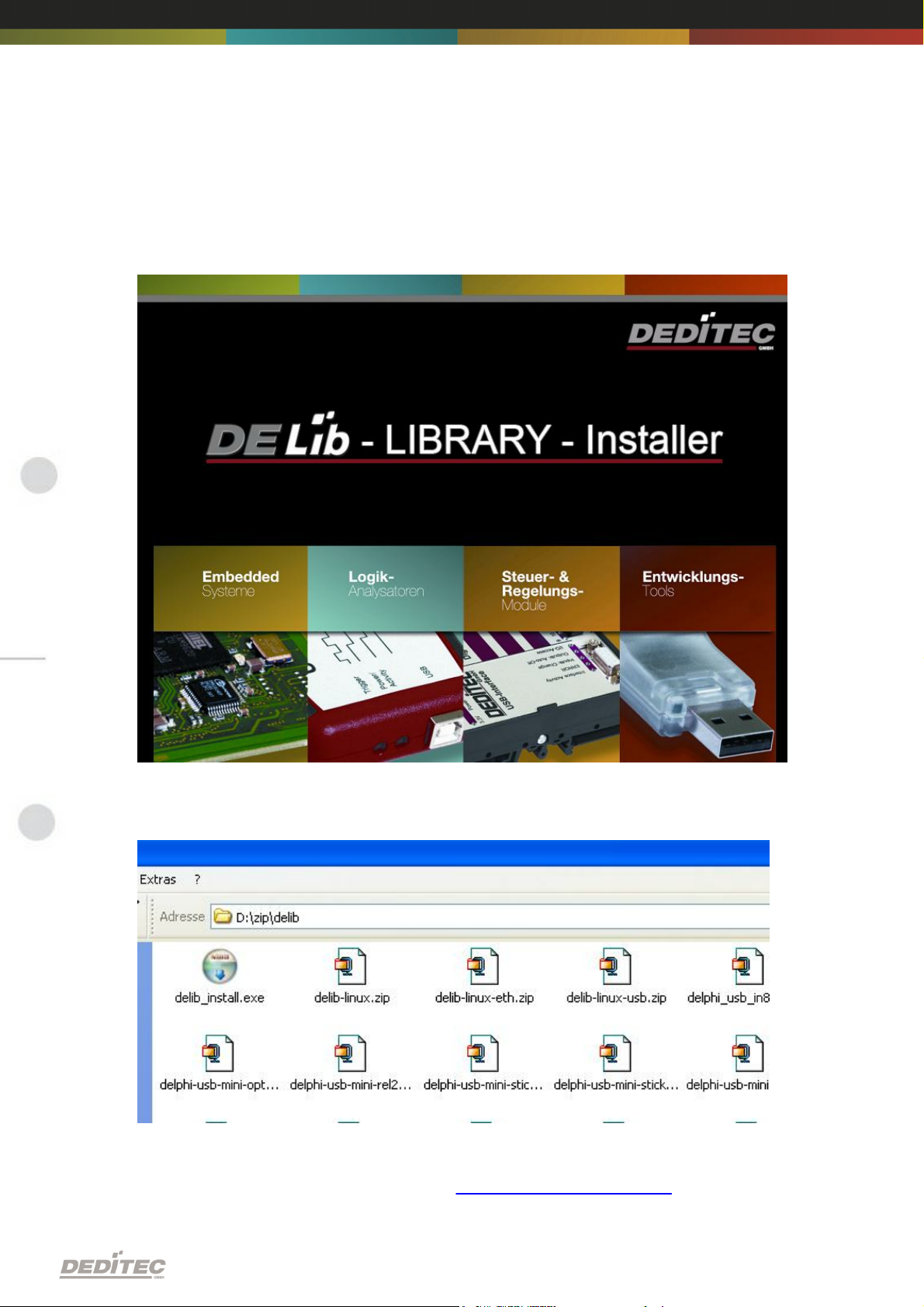
Our DELIB installer start screen.
Insert the DEDITEC driver CD into the drive and start „delib_install.exe“. The
DELIB driver library is also available on http://www.deditec.en/delib
Software |Seite 24
Page 25
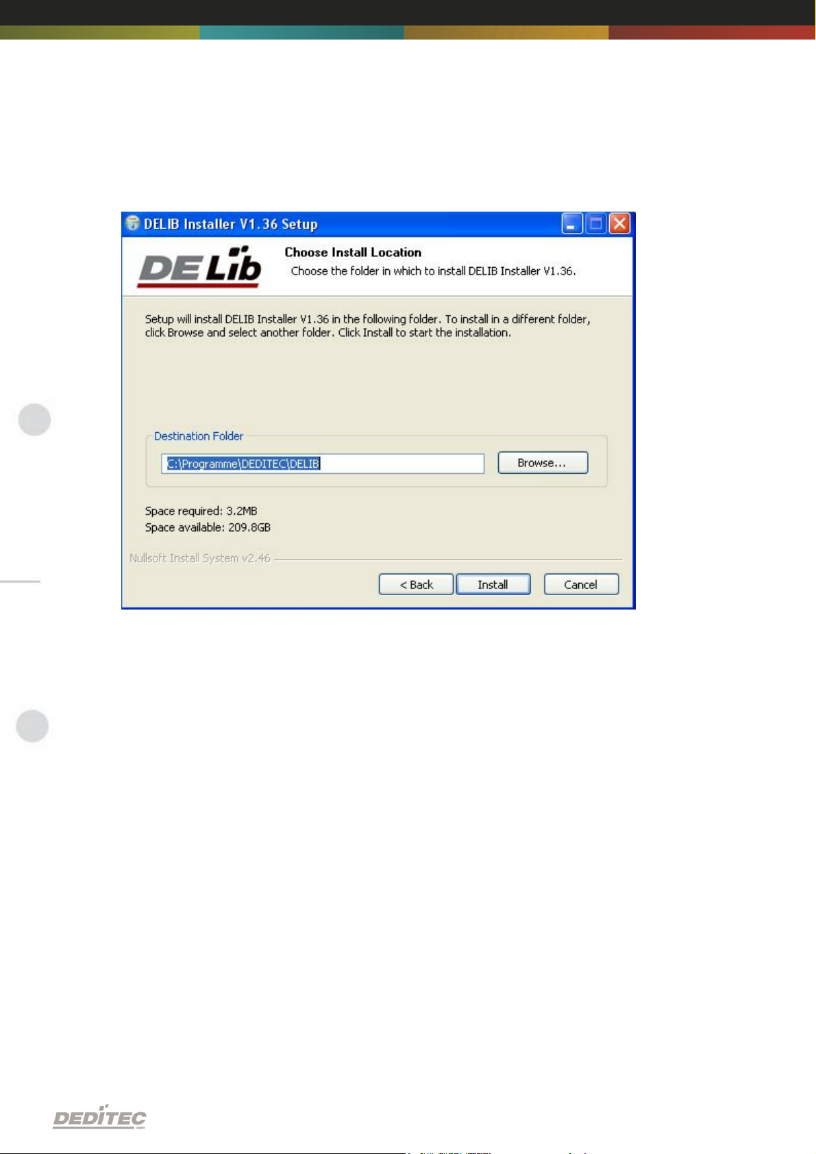
Click on „Install“.
Software |Seite 25
Page 26
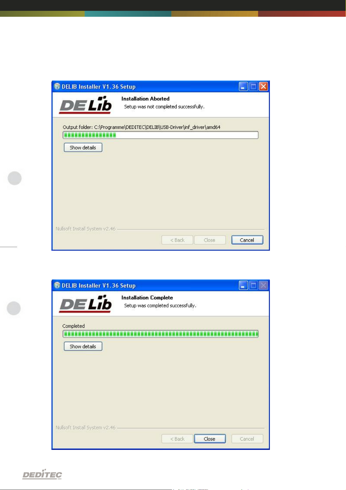
The drivers will be installed.
Software |Seite 26
Page 27
The DELIB driver library is now installed. Press „Close“ to finish the installation.
You can configure your module with the „DELIB Configuration Utility“ (see next
chapter). This is only necessary, if more than one module is present.
Software |Seite 27
Page 28
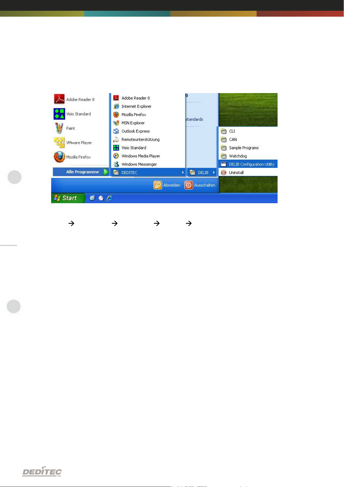
3.2.5. DELIB Configuration Utility
Start the “DELIB Configuration Utility” as follows:
Start Programs DEDITEC DELIB DELIB Configuration Utility.
The „DELIB Configuration Utility“ is a program to configure and subdivide
identical USB-modules in the system. This is only necessary if more than one
module is present.
Software |Seite 28
Page 29
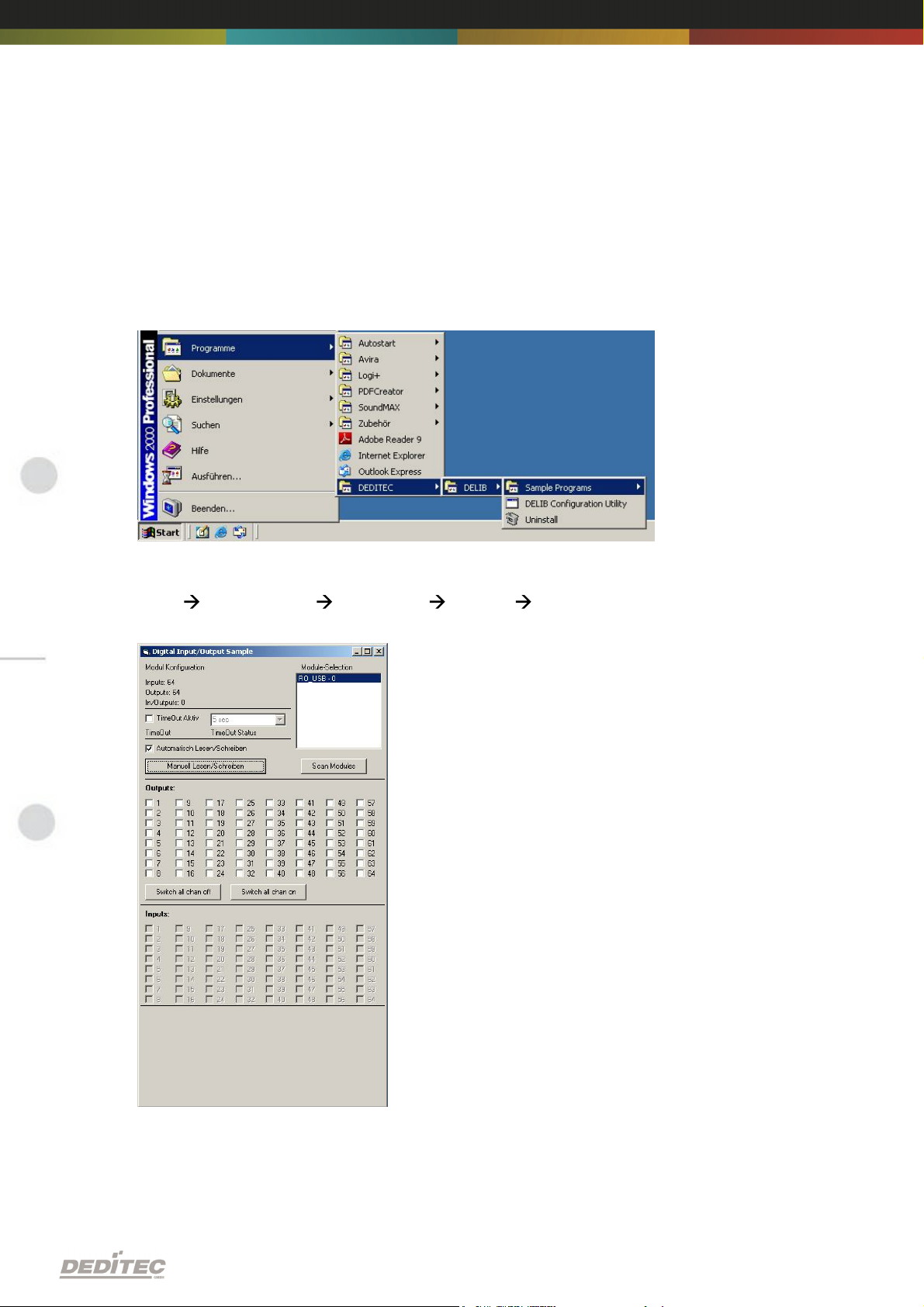
3.3. Test programs
3.3.1. Digital Input-Output Demo
Start “Digital Input-Output Demo” as follows:
Start Programme DEDITEC DELIB Digital Input-Output Demo.
The screenshot shows a test of the RO-USB-O64-R64. The configuration of the
module (64 inputs and 64 outputs) is shown on the upper left side.
Software |Seite 29
Page 30
DELIB API reference
IV
DELIB API reference |Seite 30
Page 31
4. DELIB API reference
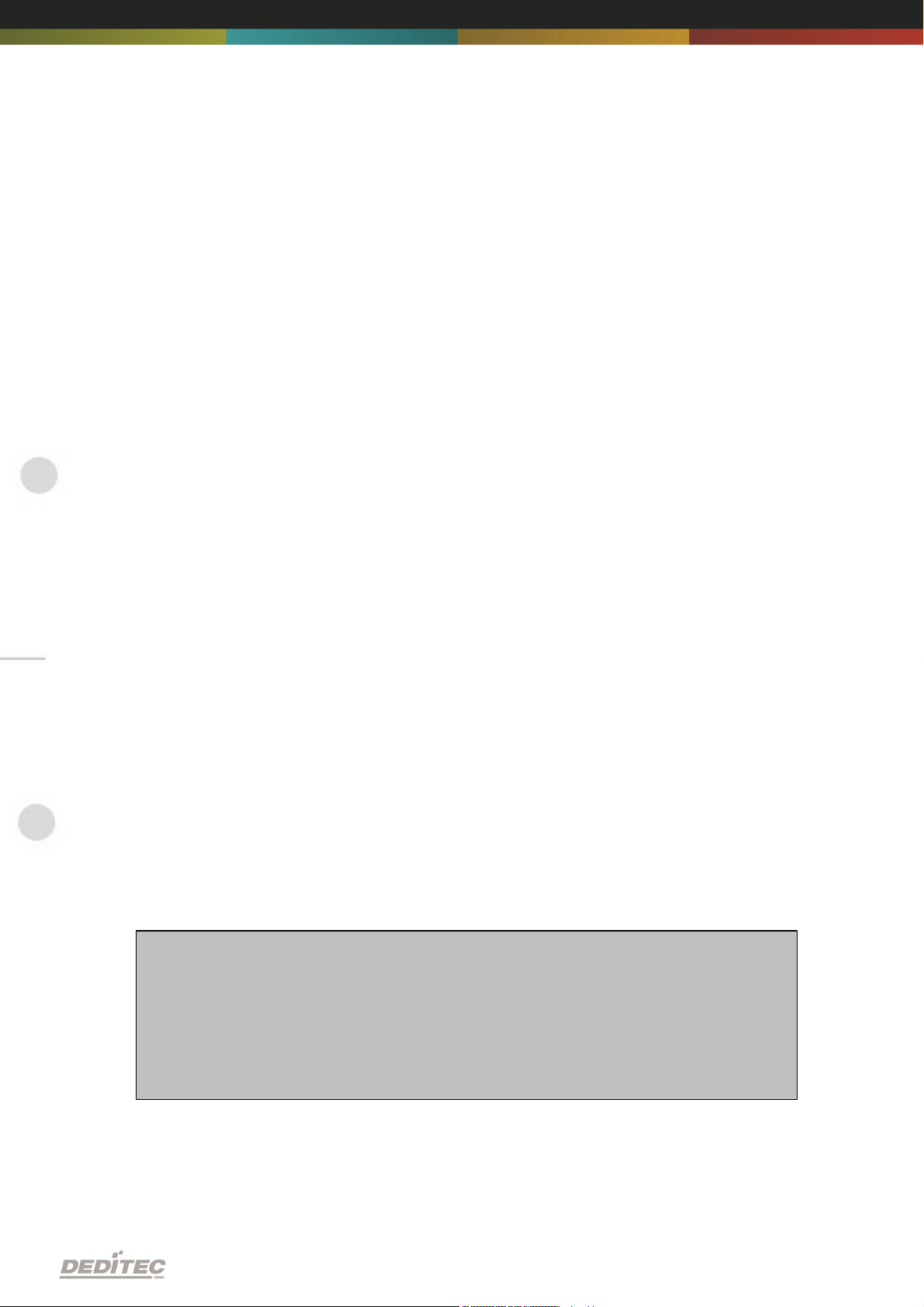
// USB-Modul öffnen
handle = DapiOpenModule(RO_USB1, 0);
printf("handle = %x\n", handle);
if (handle==0)
{
// USB Modul wurde nicht gefunden
printf("Modul konnte nicht geöffnet werden\n");
return;
}
4.1. Management functions
4.1.1. DapiOpenModule
Description
This function opens a particular module.
Definition
ULONG DapiOpenModule(ULONG moduleID, ULONG nr);
Parameters
moduleID=Specifies the module, which is to be opened (see delib.h)
nr=Indicates No of module which is to be opened.
nr=0 -> 1. module
nr=1 -> 2. module
Return value
handle=handle to the corresponding module
handle=0 -> Module was not found
Remarks
The handle returned by this function is needed to identify the module for all other
functions.
Example program
DELIB API reference |Seite 31
Page 32
4.1.2. DapiCloseModule
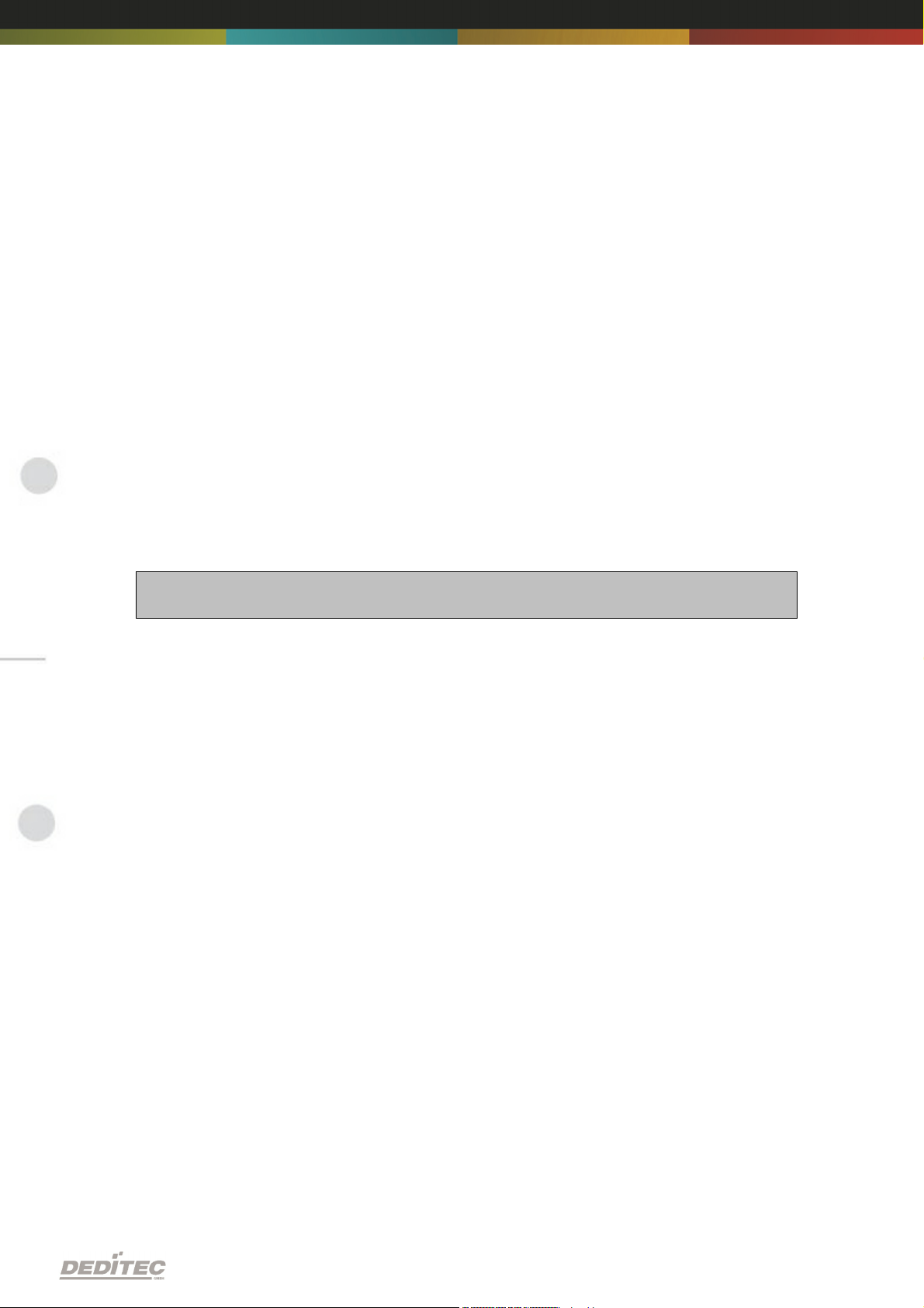
// Close the module
DapiCloseModule(handle);
Description
This command closes an opened module.
Definition
ULONG DapiCloseModule(ULONG handle);
Parameters
handle=This is the handle of an opened module
Return value
none
Example program
DELIB API reference |Seite 32
Page 33
4.1.3. DapiGetDELIBVersion
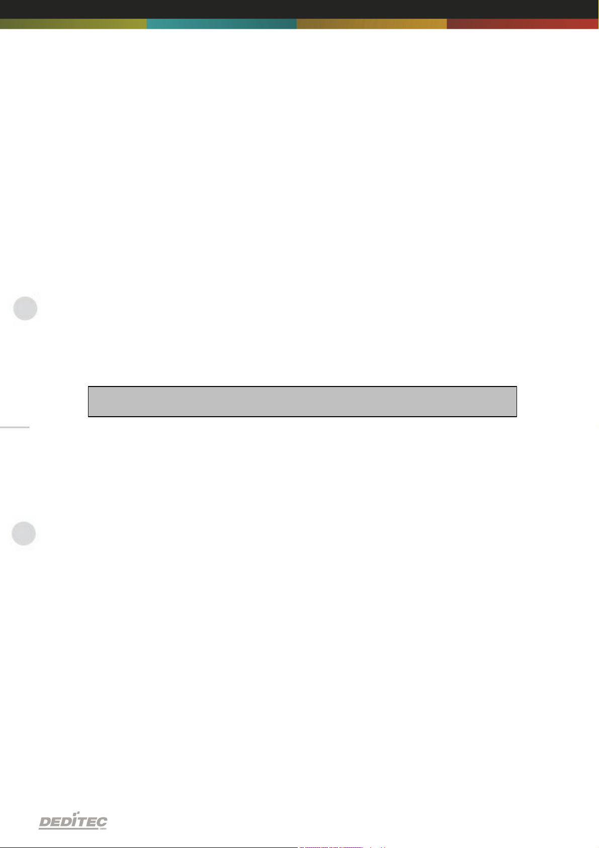
version = DapiGetDELIBVersion(0, 0);
//Bei installierter Version 1.32 ist version = 132(hex)
Description
This function returns the installed DELIB version.
Definition
ULONG DapiGetDELIBVersion(ULONG mode, ULONG par);
Parameters
mode=Mode, with which the version is readout (must be 0).
par=This parameter is not defined (must be 0).
Return value
version=Version number of the installed DELIB version [hex].
Example program
DELIB API reference |Seite 33
Page 34
4.1.4. DapiSpecialCMDGetModuleConfig
Description
This command returns the hardware equipment (number of in-/output channels) of
the module.
Definition
ULONG DapiSpecialCommand(ULONG handle,
DAPI_SPECIAL_CMD_GET_MODULE_CONFIG, par, 0, 0);
Parameters
handle=This is the handle of an open module.
Get number of digital input channels
par=DAPI_SPECIAL_GET_MODULE_CONFIG_PAR_DI
Get number of digital output channels
par=DAPI_SPECIAL_GET_MODULE_CONFIG_PAR_DO
Get number of digital in-/output channels
par=DAPI_SPECIAL_GET_MODULE_CONFIG_PAR_DX
Get number of analog input channels
par=DAPI_SPECIAL_GET_MODULE_CONFIG_PAR_AD
Get number of analog output channels
par=DAPI_SPECIAL_GET_MODULE_CONFIG_PAR_DA
Get number of stepper channels
par=DAPI_SPECIAL_GET_MODULE_CONFIG_PAR_STEPPER
DELIB API reference |Seite 34
Page 35

Return value
ret=DapiSpecialCommand(handle, DAPI_SPECIAL_CMD_GET_MODULE_CONFIG,
DAPI_SPECIAL_GET_MODULE_CONFIG_PAR_DI, 0, 0);
//Gibt die Anzahl der digitalen Eingangskanäle zurück
ret=DapiSpecialCommand(handle, DAPI_SPECIAL_CMD_GET_MODULE_CONFIG,
DAPI_SPECIAL_GET_MODULE_CONFIG_PAR_DO, 0, 0);
//Gibt die Anzahl der digitalen Ausgangskanäle zurück
ret=DapiSpecialCommand(handle, DAPI_SPECIAL_CMD_GET_MODULE_CONFIG,
DAPI_SPECIAL_GET_MODULE_CONFIG_PAR_DX, 0, 0);
//Gibt die Anzahl der digitalen Ein-/Ausgangskanäle zurück
ret=DapiSpecialCommand(handle, DAPI_SPECIAL_CMD_GET_MODULE_CONFIG,
DAPI_SPECIAL_GET_MODULE_CONFIG_PAR_AD, 0, 0);
//Gibt die Anzahl der analogen Eingangskanäle zurück
ret=DapiSpecialCommand(handle, DAPI_SPECIAL_CMD_GET_MODULE_CONFIG,
DAPI_SPECIAL_GET_MODULE_CONFIG_PAR_DA, 0, 0);
//Gibt die Anzahl der analogen Ausgangskanäle zurück
ret=DapiSpecialCommand(handle, DAPI_SPECIAL_CMD_GET_MODULE_CONFIG,
DAPI_SPECIAL_GET_MODULE_CONFIG_PAR_STEPPER, 0, 0);
//Gibt die Anzahl der Stepperkanäle zurück
Get number of digital input channels
return=Number of digital input channels
Get number of digital output channels
return=Number of digital output channels
Get number of digital in-/output channels
return=Number of digital in-/output channels
Get number of analog input channels
return=Number of analog input channels
Get number of analog output channels
return=Number of analog output channels
Get number of stepper channels
return=Number of stepper channels
Example program
DELIB API reference |Seite 35
Page 36
4.2. Error handling
ULONG error;
error=DapiGetLastError();
if(error==0) return FALSE;
printf("ERROR = %d", error);
4.2.1. DapiGetLastError
Description
This function returns the last registered error.
Definition
ULONG DapiGetLastError();
Parameters
None
Return value
Error code
0=no error. (see delib.h)
Example program
DELIB API reference |Seite 36
Page 37
4.2.2. DapiGetLastErrorText
BOOL IsError ()
{
if (DapiGetLastError () != DAPI_ERR_NONE)
{
unsigned char msg[500];
DapiGetLastErrorText((unsigned char*) msg, sizeof(msg));
printf ("Error Code = %x * Message = %s\n", 0, msg);
return TRUE;
}
return FALSE;
}
Description
This function reads the text of the last registered error.
Definition
extern ULONG __stdcall DapiGetLastErrorText(unsigned char * msg, unsigned long
msg_length);
Parameters
msg = text buffer
msg_length = length of the buffer
Example program
DELIB API reference |Seite 37
Page 38
4.3. Set TTL-In-/Outputs direction
DapiSpecialCommand(handle, DAPI_SPECIAL_CMD_SET_DIR_DX_8, 0, 1, 0);
// Set Dir of TTL-I/O CH0 to out
4.3.1. DAPI_SPECIAL_CMD_SET_DIR_DX_8
Description
This command sets the direction of the TTL-In/Outputs (8-Bit way).
Definition
void DapiSpecialCommand(ULONG handle, DAPI_SPECIAL_CMD_SET_DIR_DX_8,
ULONG ch, ULONG dir, 0);
Parameters
handle=This is the handle of an opened module.
ch=Specifies the number of the output,from which the direction will be set (0, 8, 16,
24 ..). Values between are invalid.
dir=(8-Bit) gives the direction for 8 In/Outputs. (1=output / 0=input)
Example program
DELIB API reference |Seite 38
Page 39
4.4. Reading Digital inputs
4.4.1. DapiDIGet1
Description
This command reads a single digit input.
Definition
ULONG DapiDIGet1(ULONG handle, ULONG ch);
Parameters
handle=This is the handle of an opened module.
ch=Specifies the number of input that is to be read (0 ..).
Return value
State of the input (0 / 1).
DELIB API reference |Seite 39
Page 40
4.4.2. DapiDIGet8
Description
This command reads 8 digital inputs simultaneously.
Definition
ULONG DapiDIGet8(ULONG handle, ULONG ch);
Parameters
handle=This is the handle of an opened module.
ch=Specifies the number of the input, from which it begins to read from (0, 8, 16,
24, 32, ..)
Return value
State of the read inputs.
DELIB API reference |Seite 40
Page 41
4.4.3. DapiDIGet16
Description
This command reads 16 digital inputs simultaneously.
Definition
ULONG DapiDIGet16(ULONG handle, ULONG ch);
Parameters
handle=This is the handle of an opened module.
ch=Specifies the number of the input, from which it begins to read from (0, 16, 32,
..)
Return value
State of the read inputs.
DELIB API reference |Seite 41
Page 42

4.4.4. DapiDIGet32
unsigned long data;
// ---------------------------------------------------// Einen Wert von den Eingängen lesen (Eingang 1-31)
data = (unsigned long) DapiDIGet32(handle, 0);
// Chan Start = 0
printf("Eingang 0-31 : 0x%x\n", data);
printf("Taste für weiter\n");
getch();
// ---------------------------------------------------// Einen Wert von den Eingängen lesen (Eingang 32-64)
data = (unsigned long) DapiDIGet32(handle, 32);
// Chan Start = 32
printf("Eingang 32-64 : 0x%x\n", data);
printf("Taste für weiter\n");
getch();
Description
This command reads 32 digital inputs simultaneously.
Definition
ULONG DapiDIGet32(ULONG handle, ULONG ch);
Parameters
handle=This is the handle of an opened module.
ch=Specifies the number of the input, from which it begins to read from (0, 32, 64,
..)
Return value
State of the read inputs.
Example program
DELIB API reference |Seite 42
Page 43
4.4.5. DapiDIGet64
Description
This command reads 64 digital inputs simultaneously.
Definition
ULONGLONG DapiDIGet64(ULONG handle, ULONG ch);
Parameters
handle=This is the handle of an opened module.
ch=Specifies the number of the input,from which it begins to read from (0, 64, ..)
Return value
State of the read inputs.
DELIB API reference |Seite 43
Page 44
4.4.6. DapiDIGetFF32
Description
This command reads the flip-flops from the inputs and resets them. (Input state
change).
Definition
ULONG DapiDIGetFF32(ULONG handle, ULONG ch);
Parameters
handle=This is the handle of an opened module .
ch=Specifies the number of the input, from which it begins to read from (0, 32, ..)
Return value
State of 32 input change states
DELIB API reference |Seite 44
Page 45

4.4.7. DapiDIGetCounter
value = DapiDIGetCounter(handle, 0 ,0);
// Reading counter of DI Chan 0
value = DapiDIGetCounter(handle, 1 ,0);
// Reading counter of DI Chan 1
value = DapiDIGetCounter(handle, 8 ,0);
// Reading counter of DI Chan 8
value = DapiDIGetCounter(handle, 0 ,DAPI_CNT_MODE_READ_WITH_RESET);
// Reading AND resetting counter of DI Chan 0
value = DapiDIGetCounter(handle, 1, DAPI_CNT_MODE_READ_LATCHED);
// Reading the latched counter of DI Chan 1
Description
This command reads the counter of a digital input
Definition
ULONG DapiDIGetCounter(ULONG handle, ULONG ch, ULONG mode);
Parameters
handle=This is the handle of an opened module.
ch=Specifies the digital input,from which the counter will be read.
mode=0 (Normal counter function)
mode=DAPI_CNT_MODE_READ_WITH_RESET (Reading and resetting the
counter)
mode=DAPI_CNT_MODE_READ_LATCHED (Reading the latched counter)
Return value
Value of the counter.
Example program
DELIB API reference |Seite 45
Page 46
4.5. Setting Digital outputs
4.5.1. DapiDOSet1
Description
This is the command to set a single output.
Definition
void DapiDOSet1(ULONG handle, ULONG ch, ULONG data);
Parameters
handle=This is the handle of an opened module
ch=Specifies the number of the output to be set to (0 ..)
data=Specifies the data value that is to be written (0 / 1)
Return value
None
DELIB API reference |Seite 46
Page 47
4.5.2. DapiDOSet8
Description
This command sets 8 digital outputs simultaneously.
Definition
void DapiDOSet8(ULONG handle, ULONG ch, ULONG data);
Parameters
handle=This is the handle of an opened module
ch=Specifies the number of the output, from which it begins to write to (0, 8, 16, 24,
32, ..)
data=Specifies the data values, to write to the outputs
Return value
None
DELIB API reference |Seite 47
Page 48
4.5.3. DapiDOSet16
Description
This command sets 16 digital outputs simultaneously.
Definition
void DapiDOSet16(ULONG handle, ULONG ch, ULONG data);
Parameters
handle=This is the handle of an opened module
ch=Specifies the number of the output, from which it begins to write to (0, 16, 32, ..)
data=Specifies the data values, to write to the outputs
Return value
None
DELIB API reference |Seite 48
Page 49

4.5.4. DapiDOSet32
// Einen Wert auf die Ausgänge schreiben
data = 0x0000ff00; // Ausgänge 9-16 werden auf 1 gesetzt
DapiDOSet32(handle, 0, data); // Chan Start = 0
printf("Schreibe auf Ausgänge Daten=0x%x\n", data);
printf("Taste für weiter\n");
getch();
// ---------------------------------------------------// Einen Wert auf die Ausgänge schreiben
data = 0x80000000; // Ausgang 32 wird auf 1 gesetzt
DapiDOSet32(handle, 0, data); // Chan Start = 0
printf("Schreibe auf Ausgänge Daten=0x%x\n", data);
printf("Taste für weiter\n");
getch();
// ---------------------------------------------------// Einen Wert auf die Ausgänge schreiben
data = 0x80000000; // Ausgang 64 wird auf 1 gesetzt
DapiDOSet32(handle, 32, data); // Chan Start = 32
printf("Schreibe auf Ausgänge Daten=0x%x\n", data);
printf("Taste für weiter\n");
getch();
Description
This command sets 32 digital outputs simultaneously.
Definition
void DapiDOSet32(ULONG handle, ULONG ch, ULONG data);
Parameters
handle=This is the handle of an opened module
ch=Specifies the number of the output, from which it begins to write to (0, 32, 64, ..)
data=Specifies the data values, to write to the outputs
Return value
None
Example program
DELIB API reference |Seite 49
Page 50
4.5.5. DapiDOSet64
Description
This command is to set 64 digital outputs.
Definition
void DapiDOSet64(ULONG handle, ULONG ch, ULONG data);
Parameters
handle=This is the handle of an opened module
ch=Specifies the number of the output, from which it begins to write to (0, 64, ..)
data=Specifies the data values, to write to the outputs
Return value
None
DELIB API reference |Seite 50
Page 51
4.5.6. DapiDOReadback32
Description
This command reads back the 32 digital outputs.
Definition
ULONG DapiDOReadback32(ULONG handle, ULONG ch);
Parameters
handle=This is the handle of an opened module
ch=Specifies the number of the input, from which it begins to read from (0, 32, ..)
Return value
Status of 32 outputs.
DELIB API reference |Seite 51
Page 52
4.5.7. DapiDOReadback64
Description
This command reads back the 64 digital outputs.
Definition
ULONGLONG DapiDOReadback64(ULONG handle, ULONG ch);
Parameters
handle=This is the handle of an opened module
ch=Specifies the number of the input, from which it begins to read from (0, 64, ..)
Return value
Status of 64 outputs.
DELIB API reference |Seite 52
Page 53

4.6. Example program
//***************************************************************************
//***************************************************************************
//***************************************************************************
//***************************************************************************
//***************************************************************************
//
//
// product: usb-ttl-32 (ModuleID = USB_TTL_32)
// configuration: ttl-io
// programming language: vc
//
//
// (c) DEDITEC GmbH, 2011
// web: http://www.deditec.de/
// mail: [email protected]
//
//
//***************************************************************************
//***************************************************************************
//***************************************************************************
//***************************************************************************
//***************************************************************************
//
//
// Please include the following library on linking: delib.lib
//
// This can be done at the project settings (Project/Settings/Link ->
// Object/library modules) .. extend the existing line with the ending
// "$(DELIB_LIB)\delib.lib" (with quotation marks)
//
// Including the header file delib.h (Project/Settings/C/C++ -> select
category
// "Preprocessor" -> Additional inlude directories) .. enter the line
// "$(DELIB_INCLUDE)" (with quotation marks)
#include <windows.h>
#include <stdio.h>
#include "conio.h"
#include "delib.h"
// --------------------------------------------------------------------------// GetLastError function
BOOL IsError()
{
unsigned char msg[500];
if (DapiGetLastError() != DAPI_ERR_NONE)
{
DapiGetLastErrorText((unsigned char*) msg, sizeof(msg));
printf("Error Code = %x * Message = %s\n", 0, msg);
DELIB API reference |Seite 53
Page 54

DapiClearLastError();
return TRUE;
}
return FALSE;
}
//***************************************************************************
//***************************************************************************
//***************************************************************************
//***************************************************************************
//***************************************************************************
void main(void)
{
unsigned long handle;
unsigned long data;
// --------------------------------------------------------------------
// Open Module
handle = DapiOpenModule(USB_TTL_32,0);
printf("Module handle = %x\n", handle);
// --------------------------------------------------------------------
// Module not found!
if (handle==0)
{
printf("Could not open module!\n");
printf("Press any key to exit\n");
getch();
return;
}
// -------------------------------------------------------------------
// Module found!
printf("Module has been opened\n");
// -------------------------------------------------------------------
// Switch i/o to inputs
DapiSpecialCommand(handle, DAPI_SPECIAL_CMD_SET_DIR_DX_8, 0, 0, 0);
IsError();
printf("Channel 0-7 has been set to inputs\n");
printf("Press any key to continue\n");
getch();
// -------------------------------------------------------------------
// Read value of inputs 0-7
data = DapiDIGet8(handle, 0);
IsError();
DELIB API reference |Seite 54
Page 55

printf("Value of inputs 0-7 = %d\n", data);
printf("Press any key to continue\n");
getch();
// -------------------------------------------------------------------
// Switch i/o to outputs
DapiSpecialCommand(handle, DAPI_SPECIAL_CMD_SET_DIR_DX_8, 0, 255, 0);
IsError();
printf("Channel 0-7 has been set to outputs\n");
printf("Press any key to continue\n");
getch();
// -------------------------------------------------------------------
// Write values to outputs 0-7
DapiDOSet8(handle, 0, 0xf0);
IsError();
printf("Write 0xf0 to outputs 0-7\n");
printf("Press any key to continue\n");
getch();
// -------------------------------------------------------------------
// Readback a value of inputs 0-7
data = DapiDIGet8(handle, 0);
IsError();
printf("Readback input 0-7 (from output 0-7)\n");
printf("value = %d\n", data);
printf("Press any key to continue\n");
getch();
// -------------------------------------------------------------------
// Close Module
DapiCloseModule(handle);
printf("Module closed\n");
printf("End of program!\n");
printf("Press any key to exit\n");
getch();
return ;
}
DELIB API reference |Seite 55
Page 56
Appendix
V
Appendix |Seite 56
Page 57
5. Appendix
5.1. Revisions
Rev 2.00 First DEDITEC issue
Appendix |Seite 57
Page 58
5.2. Copyrights and trademarks
Linux is registered trade-mark of Linus Torvalds.
Windows CE is registered trade-mark of Microsoft Corporation.
USB is registered trade-mark of USB Implementers Forum Inc.
LabVIEW is registered trade-mark of National Instruments.
Intel is registered trade-mark of Intel Corporation
AMD is registered trade-mark of Advanced Micro Devices, Inc.
Appendix |Seite 58
 Loading...