

Page 1

RO-INTERFACE-ETH
Hardware-Description
2010
Oktober
Page 2
INDEX
1. Introduction 5
1.1. General remarks 5
1.2. Customer satisfaction 5
1.3. Customer response 5
2. Hardware description 7
2.1. Overview screen 7
2.2. Technical data 8
2.3. Plug-in connector of the module 9
2.3.1. Power supply
2.3.2. Ethernet interface
2.4. Buttons of the module 10
2.5. Controll LEDs 11
2.5.1. Definition of LEDs
11
3. Configuring the module 13
3.1. Configuration via DELIB Configuration utility 13
3.2. Configuration via internal web server 17
3.3. Factory settings 18
4. Firmware Update 20
4.1. DEDITEC Flasher 20
4.2. Web interface 21
9
9
5. Restore basic configuration 24
5.1. Restore IP address 24
Index | 2Seite
Page 3
INDEX
5.2. Restore firmware 24
6. Software 26
6.1. Using our products 26
6.1.1. Access via graphical applications
6.1.2. Access via the DELIB driver library
6.1.3. Access via protocol
6.1.4. Access via provided test programs
26
26
26
27
6.2. DELIB driver library 28
6.2.1. Overview
6.2.2. Supported operating systems
6.2.3. Supported programming languages
6.2.4. Installation DELIB driver library
6.2.5. DELIB Configuration Utility
28
30
30
31
33
6.3. Test programs 34
6.3.1. Digital Input-Output Demo
6.3.2. Analog Input-Output Demo
6.3.3. Stepper Demo
34
35
36
7. Appendix 38
7.1. Revisions 38
7.2. Copyrights and trademarks 39
Index | 3Seite
Page 4
Introduction
I
Introduction | Seite 4
Page 5

1. Introduction
1.1. General remarks
First of all, we would like to congratulate you to the purchase of a high quality
DEDITEC product.
Our products are being developed by our engineers according to quality
requirements of high standard. Already during design and development we take
care that our products have -besides quality- a long availability and an optimal
flexibility.
Modular design
The modular design of our products reduces the time and the cost of
development. Therefor we can offer you high quality products at a competitive
price.
Availability
Because of the modular design of our products, we have to redesign only a
module instead of the whole product, in case a specific component is no longer
available.
1.2. Customer satisfaction
Our philosophy: a content customer will come again. Therefor customer
satisfaction is in first place for us.
If by any chance, you are not content with the performance of our product,
please contact us by phone or mail immediately.
We take care of the problem.
1.3. Customer response
Our best products are co-developments together with our customers. Therefor
we are thankful for comments and suggestions.
Introduction | Seite 5
Page 6

Hardware description
II
Hardware description |Seite 6
Page 7
2. Hardware description
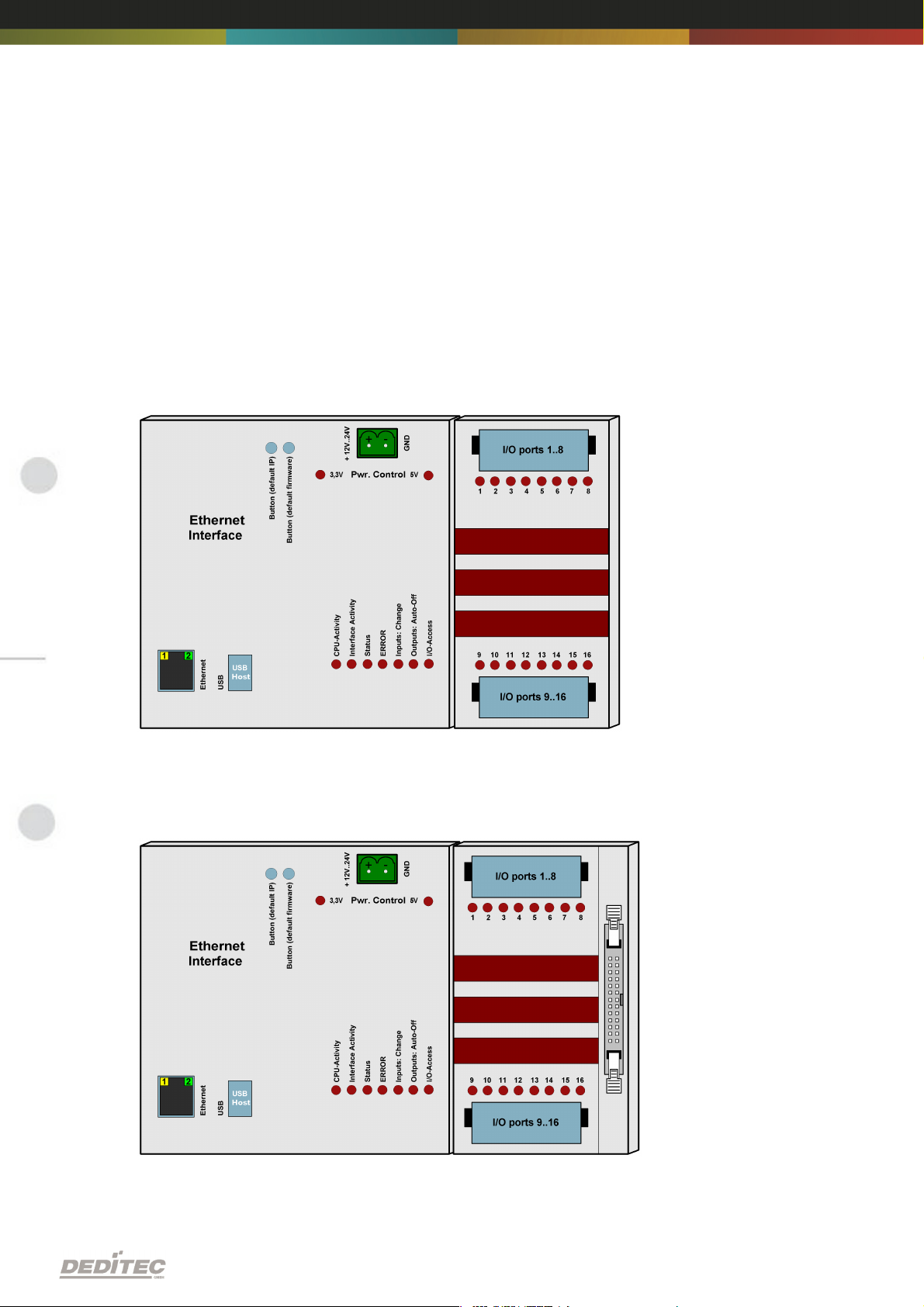
2.1. Overview screen
The figure shows the control module with ethernet interface (left side) combined
with an input/output module (right side).
The figure shows the control module with ethernet interface (left side) combined
with a flexible connector input/output module (right side).
Hardware description |Seite 7
Page 8
2.2. Technical data
Single power supply +7V..+24V DC
10/100 Mbit/sec Ethernet interface
Input/output access over TCP/IP
WEB interface
Configuration over web interface
9 Control LEDs
RJ45 Socket
Timeout feature providing ability to disconnect outputs for safety reasons
Expandable in 16 gradations
Can be combined without any problem to other modules of the RO series
Windows driver library DELIB
Hardware description |Seite 8
Page 9
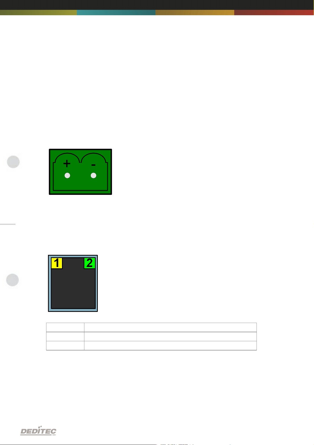
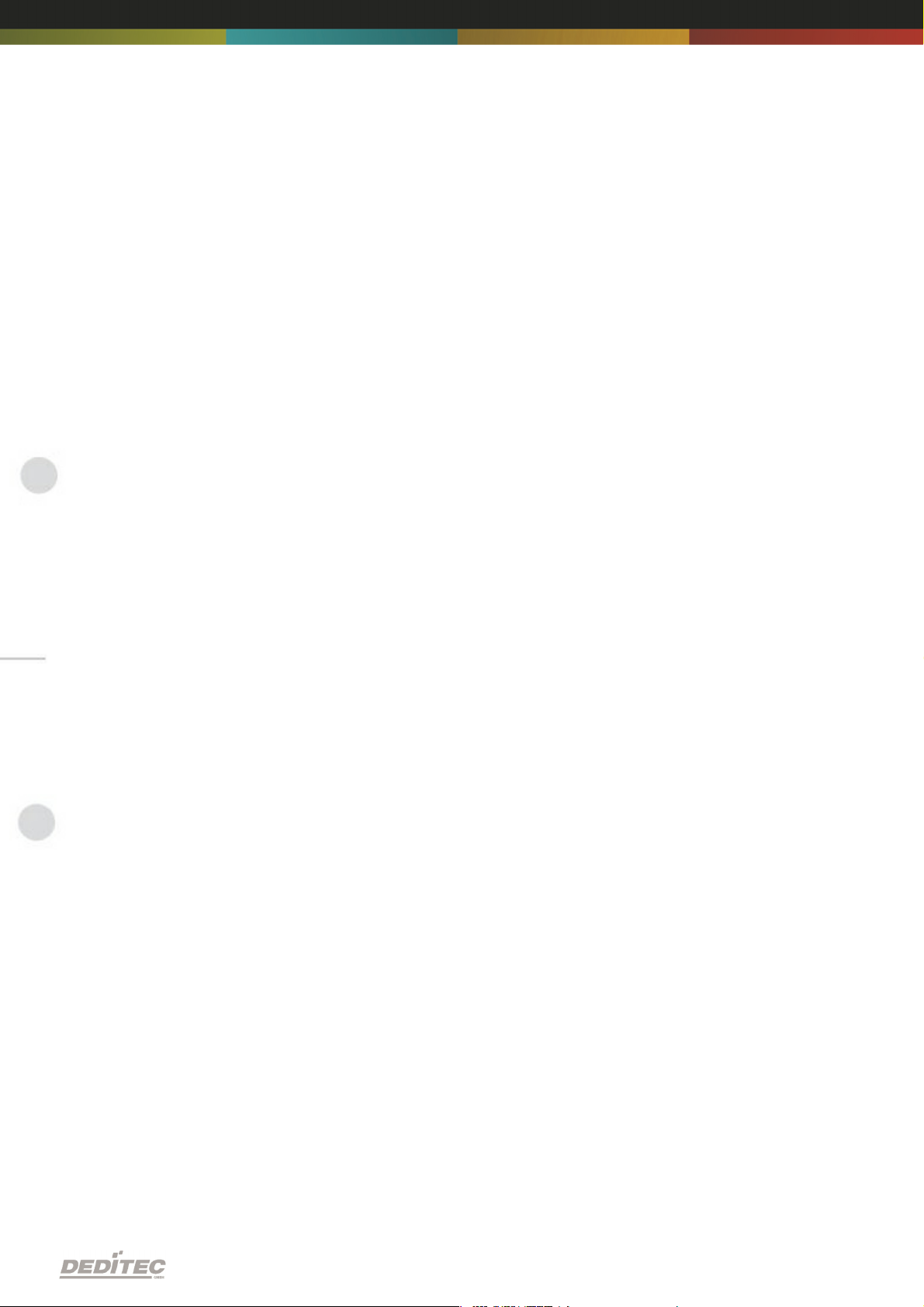
2.3. Plug-in connector of the module
LED
Description
1
Activity
2
10/100 Mbit
2.3.1. Power supply
The input-power-supply-range lies between +7V and +24V DC.The power
supply can be realized with a standard AC/DC adaptor with 1A output current. A
suitable plug-in connector is delivered.
2.3.2. Ethernet interface
The network connection is provided by a RJ45 socket.
Hardware description |Seite 9
Page 10
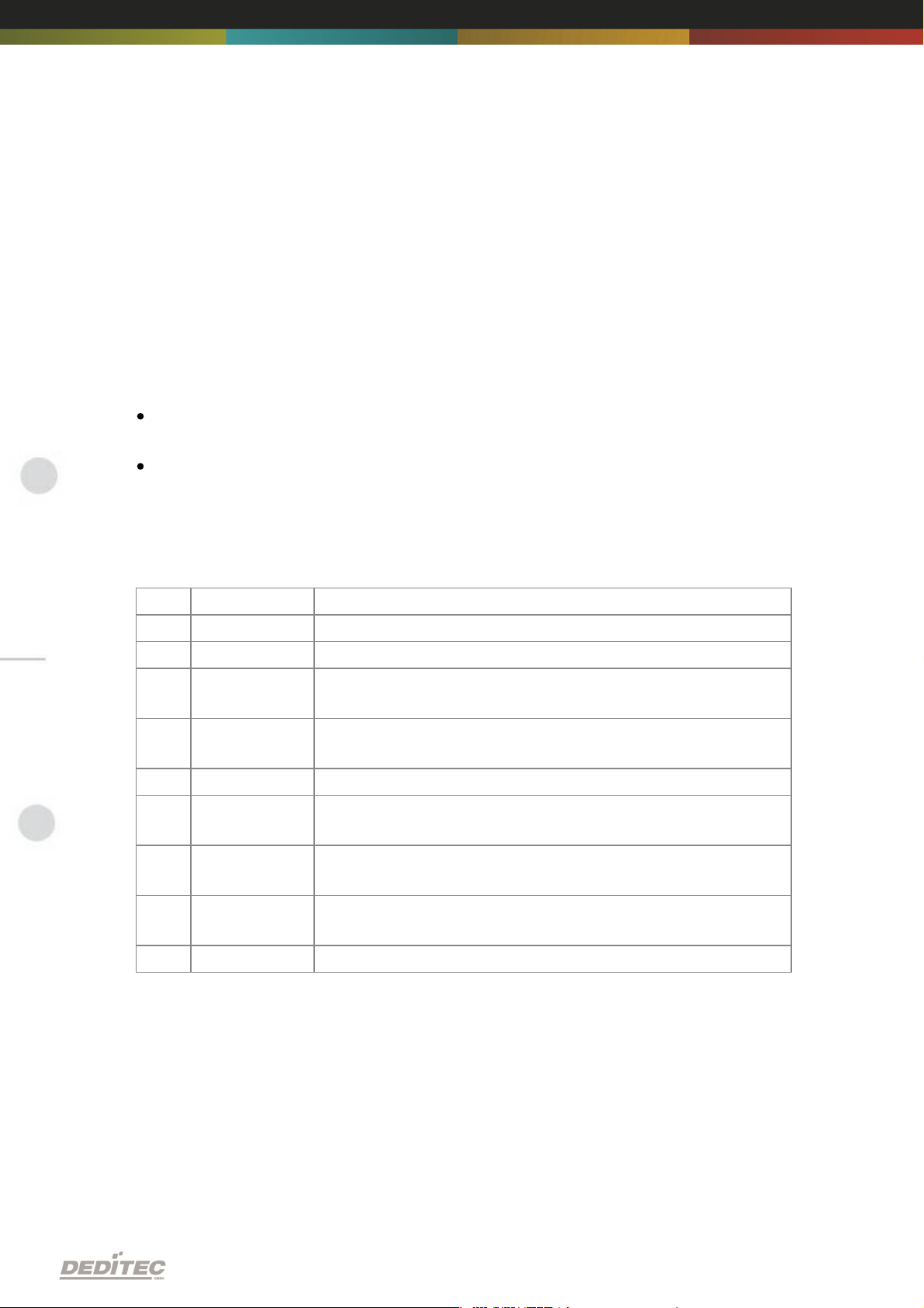
2.4. Buttons of the module
Left Button:
Reset IP address to default
(see chapter 5.1)
Right Button:
Reset firmware to factory settings.
(see chapter 5.2)
Hardware description |Seite 10
Page 11
2.5. Controll LEDs
LED
Label
Description
above
3,3V
Internal 3,3V power supply
above
5V
Internal 5V power supply
1
CPU Activity
2x flashing + long break. Operating system reports:
Status OK
2
Interface
Activity
Active communication over Ethernet
3
Status
LED is on -> Module is ready
4
ERROR
Error during ethernet-transfer (for details see document
”Serial protocol”)
5
Inputs:
Change
"State change" between 2 read-out cycles detected
6
Outputs: AutoOff
Due to timeout, all outputs are switched-off for safety
reasons
7
I/O Access
CPU-access to the connected I/O modules.
The Ethernet module has a series of control LEDs. They are used for easy visual
indication of various state functions.
While switching the module on, in normal operating mode, the module should
signalize the following sequence:
approx. 20 sec after switching the module on, LED 1 and 2 are flashing briefly.
-> Operating system has been loaded successfully.
Then LED 3 is on permanently and LED 1 is flashing. -> Module is ready.
2.5.1. Definition of LEDs
Hardware description |Seite 11
Page 12

Configuring the module
III
Configuring the module |Seite 12
Page 13

3. Configuring the module
3.1. Configuration via DELIB Configuration utility
This method allows a simple configuration of the product. Following basic
values can be changed.
Module name
IP address
Net mask
Default gateway
DNS server
Additionally with this tool all DEDITEC ethernet devices in the LAN network are
displayed.
The following pages describe how it works...
Configuring the module |Seite 13
Page 14

Start DELIB Configuration utility as follows:
Start -> Programs -> DEDITEC -> DELIB -> DELIB Configuration Utility
1.
Module Selection: select RO-ETH
2.
Find and configure RO-ETH Module
Configuring the module |Seite 14
Page 15

1.
Scan RO-ETH modules: So you can find all DEDITEC ETH modules on local
ethernet stream. Therefore we use an ethernet protocol which will not be
routed. Because of that you can configure only modules which are connected
to the bus. The advantage of this method is, that you can find modules which
are not in the same sub net, of which you are configuring.
2.
Click on the module, which you want to configure.
Configuring the module |Seite 15
Page 16

Here you can change the module name according to your wishes
1.
You can change module name, IP address, net mask, default gateway and
DNS server.
2.
Write new Values to Module.
Notice:
At the configuration of the RO-ETH module should be paid attention to the IP
address. It has to be in the same IP segment in which the control PC is. Of
course you must not select an already used IP address.
If the standard IP address of the module is not from the address range of the
network, the module will not be reachable by TCP/IP at the moment. Problems
of accessibility will also occur, if the IP address is already used. However the IP
address and the net mask of the ethernet module are configurable by this utility.
Alternatively you can connect the module to the PC and set the IP address and
the net mask directly. After the accessibility is given, the further configuration is
ensued by a browser via the integrated web server of the ethernet module.
To these belongs ask your system administrator.
Configuring the module |Seite 16
Page 17

3.2. Configuration via internal web server
The RO-ETH module has an own web server by which it can be configured, too.
Configuring the module |Seite 17
Page 18

3.3. Factory settings
The factory settings of the ethernet module include following settings:
IP address: 192.168.1.1
The factory settings can be restored by pushing the left button -> see chapter
5.2
IP address 192.168.1.1
Subnet mask 255.255.255.0
Standard gateway 192.168.1.254
Configuring the module |Seite 18
Page 19

Firmware Update
IV
Firmware Update | Seite 19
Page 20

4. Firmware Update
4.1. DEDITEC Flasher
Approach:
Download the latest firmware inclusive software update. http://www.deditec.
de/en/module/software/delib/download.html
Extract all data to one folder
Start the application deditec-flasher.exe
1.
Select the interface. For ethernet press the key "E"
2.
Select the module which you want to update. Press the key "M" for CPU
interface
3.
After successfully flashing , in the prompt appears: Flash OK!
Firmware Update | Seite 20
Page 21

4.2. Web interface
Approach:
1.
Type the IP address of your module in the browser
Firmware Update | Seite 21
Page 22

1.
Click on FW-Update
2.
Select the file “ro_cpu_eth_fw.dfw”
3.
Click on Firmware update
Firmware Update | Seite 22
Page 23

Restore basic configuration
V
Restore basic configuration | Seite 23
Page 24

5. Restore basic configuration
5.1. Restore IP address
The default value of the IP address is: 192.168.1.1
Left Button: Restore IP address to default (192.168.1.1):
To restore the IP address proceed as follow:
Push the button at least 5 sec.
After that, the left LEDs "CPU Activity" and "Interface Activity" should be
flashing four times (confirmation of receipt)
After this, the module has following settings:
IP address 192.168.1.1
Subnet mask 255.255.255.0
Standard gateway 192.168.1.254
5.2. Restore firmware
To restore the firmware to default value proceed as follow:
Right Button: Restore firmware to factory settings
To restore the firmware to factory settings proceed as follow:
Press the button at least 10sec.
After this, the three LED‘s “CPU Activity”, “Interface Activity” and “Status”
should be flashing four times (confirmation of receipt).
After this, the module restarts.
The firmware and configuration of the factory settings are now active again!
Restore basic configuration | Seite 24
Page 25

Software
VI
Software | Seite 25
Page 26

6. Software
6.1. Using our products
6.1.1. Access via graphical applications
We provide driverinterfaces e.g. for LabVIEW and ProfiLab. The DELIB driver
library is the basis, which can be directly activated by ProfiLAB.
For LabVIEW, we provide a simple driver connection with examples!
6.1.2. Access via the DELIB driver library
In the appendix, you can find the complete function reference for the integration
of our API-functions in your software. In addition we provide examples for the
following programming languages:
C
C++
C#
Delphi
VisualBasic
VB.NET
MS-Office
6.1.3. Access via protocol
The protocol for the activation of our products is open source. So you are able
to use our products on systems without Windows or Linux.
Software | Seite 26
Page 27

6.1.4. Access via provided test programs
We provide simple handling test programs for the most important functions of
our products. These will be installed automatically by the installation of the
DELIB driver library.
So you can test directly e.g. relays or you can check the voltage of an A/D
converter.
Software | Seite 27
Page 28

6.2. DELIB driver library
6.2.1. Overview
The following figure explains the structure of the DELIB driver library
The DELIB driver library allows an uniform response of DEDITEC hardware with
particular consideration of the following viewpoints:
Independent of operating system
Independent of programming language
Independent of the product
Program under diverse operating systems
The DELIB driver library allows an uniform response of our products on diverse
operating systems.
We has made sure, that all of our products can be responded by a few
commands.
Whatever which operating system you use. - Therefore the DELIB cares!
Software | Seite 28
Page 29

Program with diverse programming languages
We provide uniform commands to create own applications. This will be solved
by the DELIB driver library.
You choose the programming language!
It can be simply developed applications under C++, C, Visual Basic, Delphi or
LabVIEW®.
Program independent of the interface
Write your application independent of the interface !
Program an apllication for an USB product of us. - Also, it will work with an
ethernet or RS-232 product of us !
SDK-Kit for Programmer
Integrate the DELIB in your application. On demand you receive an installation
script for free, which allows you, to integrate the DELIB installation in your
apllication.
Software | Seite 29
Page 30

6.2.2. Supported operating systems
Our products support the following operating systems:
Windows 2000
Windows XP
Windows Vista
Windows 7
Linux
6.2.3. Supported programming languages
Our products are responsive via the following programming languages:
C
C++
C#
Delphi
VisualBasic
VB.NET
MS-Office
Software | Seite 30
Page 31

6.2.4. Installation DELIB driver library
DELIB stands for DEDITEC Library and contains the necessary libraries for the
modules in the programming languages C, Delphi and Visual Basic.
Insert the DEDITEC driver CD into the drive and start „delib_install.exe“. The
DELIB driver library is also available on http://www.deditec.en/delib
Click on „Install“.
Software | Seite 31
Page 32

The drivers will be installed.
The DELIB driver library is now installed. Press „Close“ to finish the installation.
You can configure your module with the „DELIB Configuration Utility“ (see
next chapter). This is only necessary, if more than one module is present.
Software | Seite 32
Page 33

6.2.5. DELIB Configuration Utility
Start the “DELIB Configuration Utility” as follows:
Start Programs DEDITEC DELIB DELIB Configuration Utility.
The „DELIB Configuration Utility“ is a program to configure and subdivide
identical USB-modules in the system. This is only necessary if more than one
module is present.
Software | Seite 33
Page 34

6.3. Test programs
6.3.1. Digital Input-Output Demo
Start “Digital Input-Output Demo” as follows:
Start Programme DEDITEC DELIB Digital Input-Output Demo.
The screenshot shows a test of the RO-USB-O64-R64. The configuration of the
module (64 inputs and 64 outputs) is shown on the upper left side.
Software | Seite 34
Page 35

6.3.2. Analog Input-Output Demo
Start “Analog Input-Output Demo” as follows:
Start Programme DEDITEC DELIB Analog Input-Output Demo.
The screenshot shows a test of the RO-USB-AD16-DA2_ISO. The configuration
of the module (16 A/D inputs and 2 D/A outputs) is shown on the upper left side.
Software | Seite 35
Page 36

6.3.3. Stepper Demo
Start “Stepper Demo” as follows:
Start Programme DEDITEC DELIB Stepper Demo.
The screenshot shows a test of the RO-USB-STEPPER2. The configuration of
the module (2 Stepper) is shown on the upper left side.
Software | Seite 36
Page 37

Appendix
VII
Appendix | Seite 37
Page 38

7. Appendix
7.1. Revisions
Rev 1.00 First issue
Rev 2.00 Design change
Appendix | Seite 38
Page 39

7.2. Copyrights and trademarks
Linux is registered trade-mark of Linus Torvalds.
Windows CE is registered trade-mark of Microsoft Corporation.
USB is registered trade-mark of USB Implementers Forum Inc.
LabVIEW is registered trade-mark of National Instruments.
Intel is registered trade-mark of Intel Corporation
AMD is registered trade-mark of Advanced Micro Devices, Inc.
Appendix | Seite 39
 Loading...