

Page 1
AD128
ES PLITNLENDEFR ZH
Français (page 2)
RU
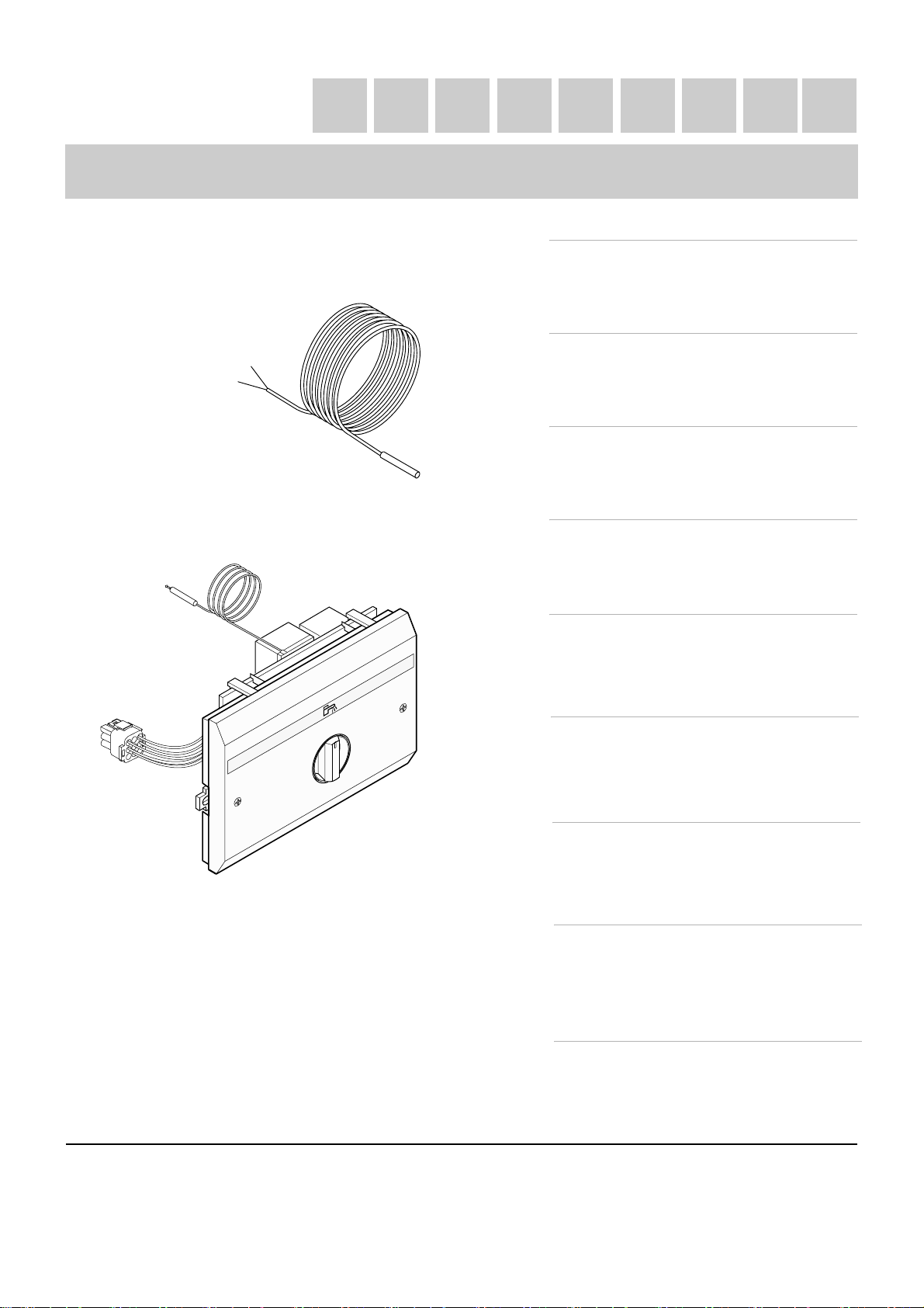
Module de régulation et de priorité eau
chaude sanitaire MB2
Deutsch (Seite 2 )
MB2-Modul zur WWE-Regelung und
Vorrangschaltung
English (page 6 )
MB2 regulation and domestic hot water
priority module
Nederlands (pagina 6 )
Regelmodule en voorrang sanitair warm
water MB2
Italiano (pagina 10)
Modulo di regolazione e di priorità acqua
calda sanitaria MB2
Español (página 10)
6
5
7
4
8
B
M
3
2
1
8801N125B
Módulo de regulación y de prioridad de
agua caliente sanitaria MB2
Polski (strona 14)
MB2 moduł priorytetu ciepłej wody
użytkowej z regulacją temperatury
РУССКИЙ (Страница 14)
Модуль регулирования и приоритета
горячей санитарно-технической воды
MB2
中文 ( 18 页)
8801-4297E (94866509)
生活热水优先调节模块 MB2
Page 2

Français
Deutsch
Le module MB2 assure la régulation de la température et la priorité à
la production de l'eau chaude sanitaire.
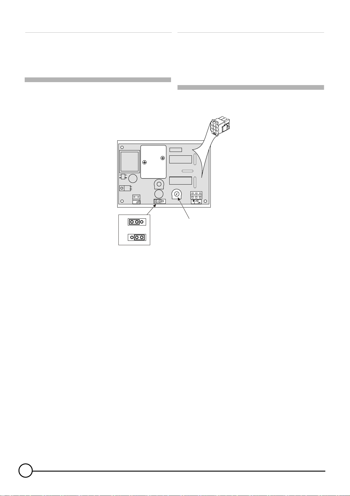
1 Réglage de la temporisation de la
pompe de charge
Mini Maxi
T
SB
T=0
Das Modul MB2 gewährleistet die Temperaturregelung und die
Warmwasserbereitung.
1 Einstellung der Ladepumpen-
Nachlaufzeit
TEMPO
118A
L N
N8801
1
2
1. Temporisation activée
2. Temporisation supprimée
3. Réglage temporisation
La temporisation de la pompe de charge autorise le fonctionnement
de la pompe de charge pendant 4 minutes (réglage d'usine) après
l'arrêt du brûleur. Ceci permet d'utiliser la chaleur résiduelle
accumulée dans le corps de chauffe pour compléter le réchauffage du
ballon en été.
La temporisation est réglable de 3 à 6 minutes à l'aide du
potentiomètre situé au dos de l'appareil.
Pour supprimer la temporisation, déplacer le pont situé au dos de
l'appareil.
3
1. Nachlauf aktiviert
2. Nachlauf aufgehoben
3. Einstellung Nachlaufzeit
Durch die Ladepumpen-Nachlaufzeit laüft die Ladepumpe nach dem
Abstellen des Brenners noch 4 Minuten (Werkeinstellung) nach. Dies
ermöglicht im Sommer die Nutzung der im Kesselblock
angesammelten Restwärme zur Aufheizung des Speichers.
Die Nachlaufzeit ist von 3 bis 6 Minuten mittels Potentiometers, der
sich auf der Geräte-Rückseite befindet, einstellbar(.
Zur Behebung der Nachlaufzeit, die Brücke die sich auf der GeräteRückseite befindet verstellen.
2
AD128 25/08/09 - 94866509 - 8801-4297E
Page 3
Français
Deutsch
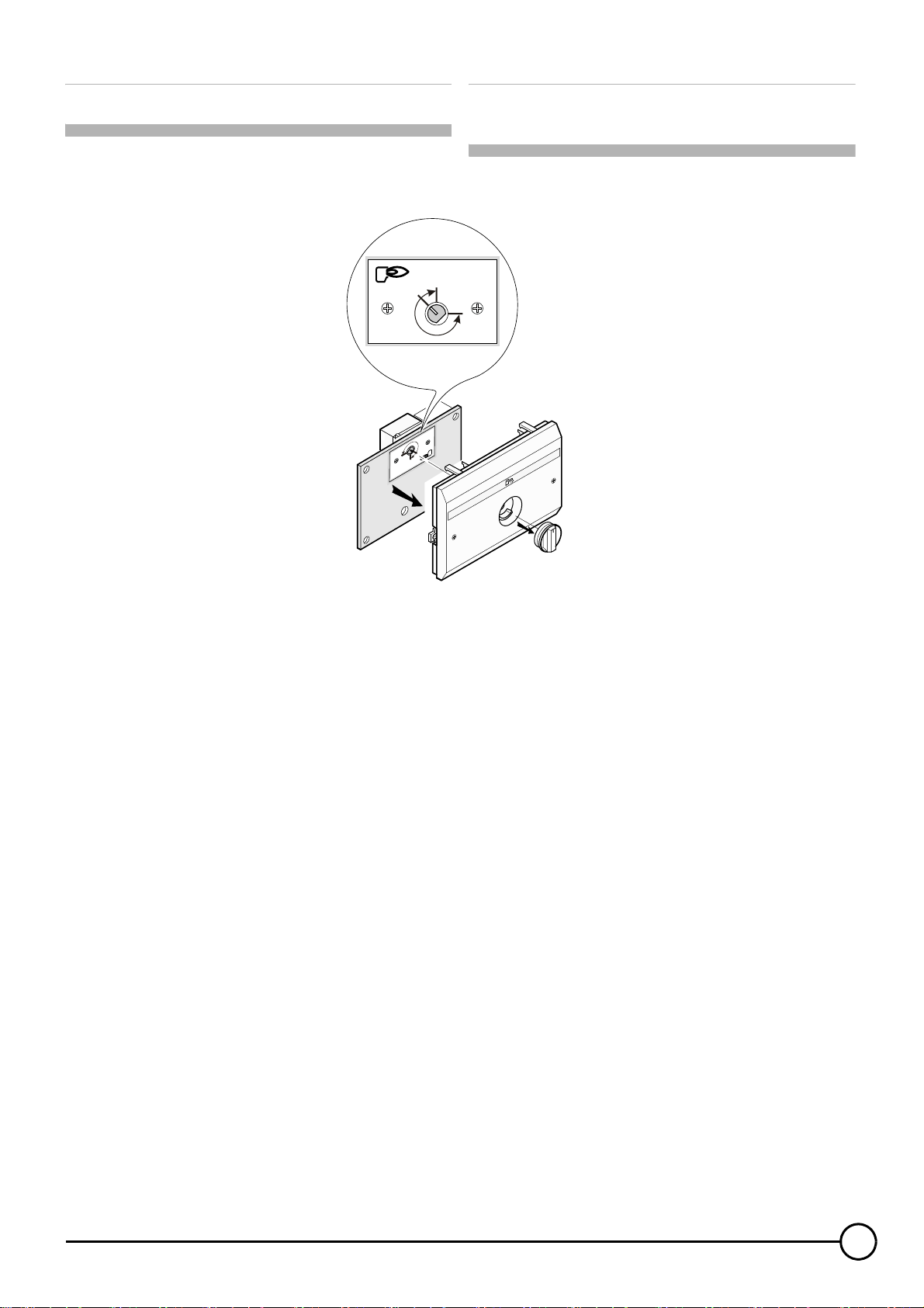
2 Réglage du thermostat limiteur
80°C
C
2 Einstellung des Temperaturwächters
90°C
30°C
80
°
C
3°
0
90°
C
6
5
7
4
8
3
2
MB
1
8801N189B
Un thermostat limiteur réglé d'usine à 80°C limite la température de
la chaudière durant la charge sanitaire.
Le thermostat limiteur est réglable de 30 à 90 °C.
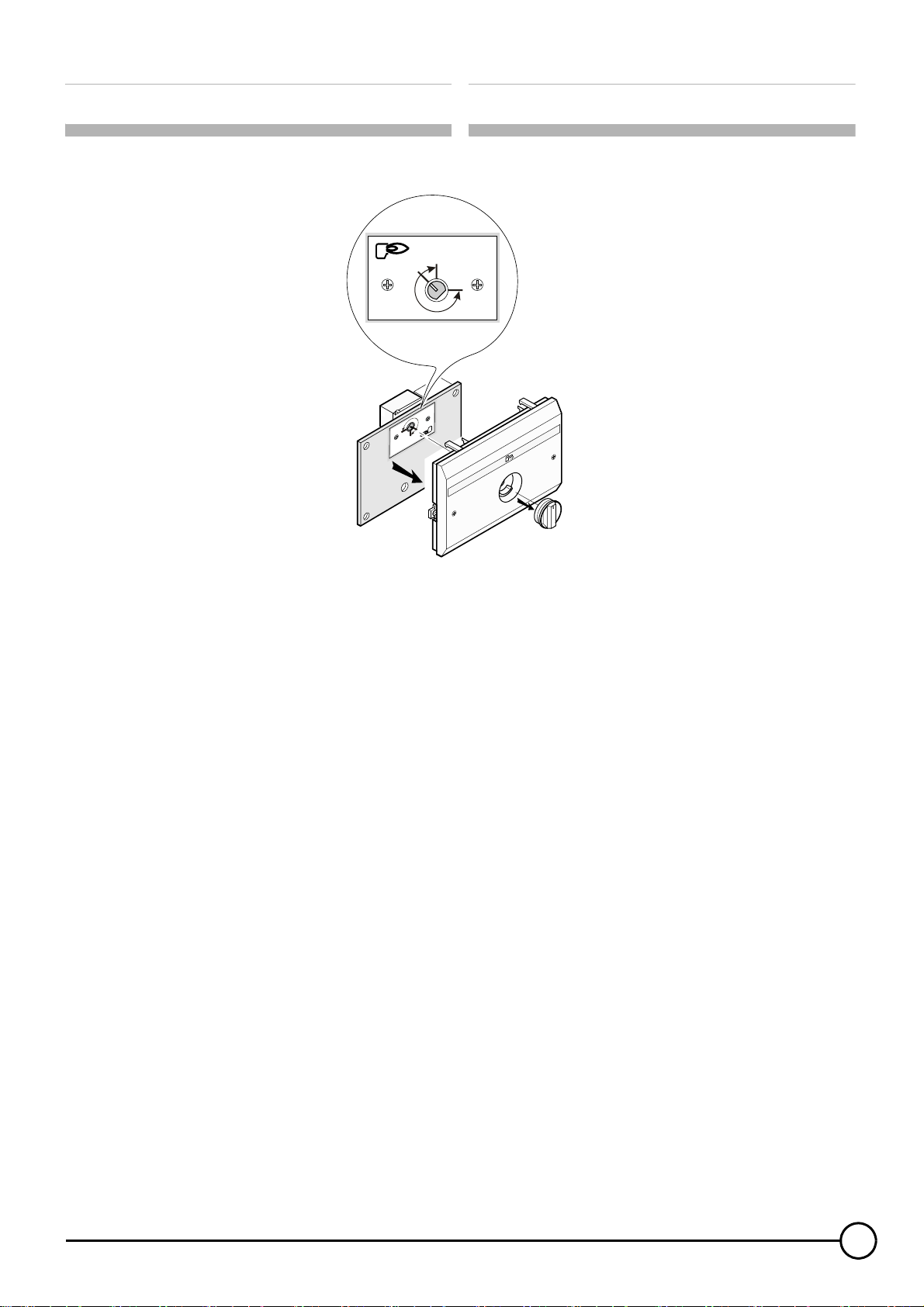
- Retirer le module du tableau de commande si nécessaire.
- Retirer le bouton du thermostat en le tirant à soi avec précaution
(utiliser une pince et un chiffon).
- Retirer la carte électronique.
- Régler le thermostat limiteur à l'aide d'un tournevis plat.
- Remonter l'ensemble.
Ein Temperaturwächter, werkseitig auf 80°C eingestellt, steuert die
Kesseltemperatur während der Speicherladephase.
Der Temperaturwächter ist auf Werte von 30 bis 90 °C einstellbar.
- Modul vom Schaltfeld wenn nötig abnehmen.
- Knopf des Temperaturwächters vorsichtig nach vorn vom Modul
abziehen (Zange mit einem Tuch zum Schutz verwenden).
- Leiterplatte herausnehmen.
- Temperaturwächter mittels Flach-Schraubenziehers einstellen.
- Die Teile wieder montieren.
25/08/09 - 94866509 - 8801-4297E AD128
3
Page 4

Français
Deutsch
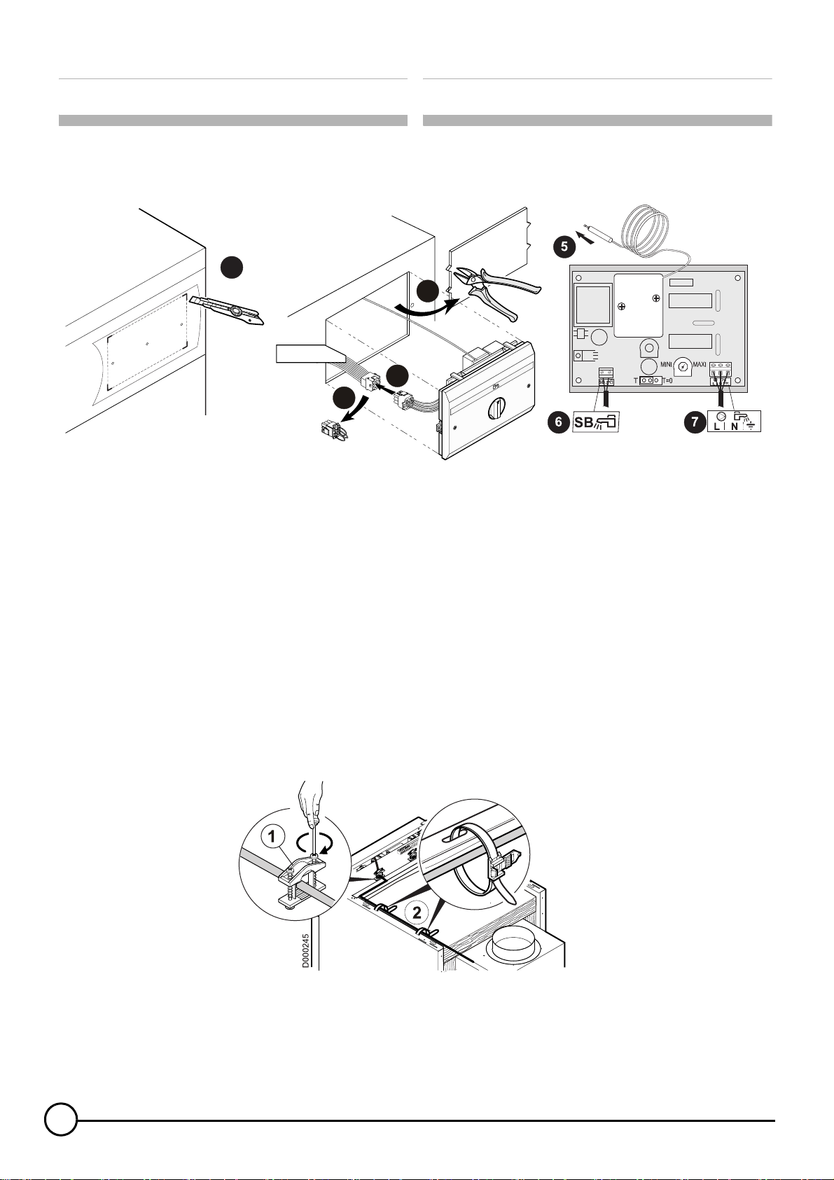
3 Montage et raccordement électrique
Exemple : DTG X / GSX N 100
Procédure similaire pour les autres produits.
1
DHW MODULE
MODULE E.C.S
BOILERVORRANGSCHALTUNG
M000292A
3
Mettre en place le bulbe du thermostat limiteur dans le doigt de
gant de la chaudière.
Raccordement de la sonde ballon.
Mettre en place le bulbe de la sonde ballon dans le doigt de
gant du ballon.
3 Montage und elektrischer Anschluss
Beispiel: DTG X / GSX N 100
Ähnliche Vorgehensweise bei anderen Produkten.
2
4
6
5
7
4
8
3
2
MB
1
00045
M1A
Fühler des Temperaturwächters in die Tauchhülse des
Heizkessels einführen.
Speichertemperaturfühler anschließen.
Fühler des Speichertemperaturfühlers in die Tauchhülse des
Speichers einführen.
M000452-B
Si le ballon possède déjà un thermostat de réglage :
- Retirer la sonde du thermostat.
- Mettre en place la nouvelle sonde ballon, fournie avec l'option
AD128
.
Dans ce cas, le thermostat du ballon ne sera plus utilisé.
Uniquement valable pour chaudière DTG X / GSX N 100
- Mettre en place le serre-câble
et les 2 colliers fournis
avec l'option AD128.
- Fixer le câble de la sonde
ballon à l'aide de l'arrêt de
traction et des serre-câbles.
Raccordement de la pompe de charge.
Séparer les câbles de sondes des câbles 230 V. Pour éviter
les interférences, respecter une distance minimum de
10 cm entre ceux-ci.
Wenn der Speicher schon einen Temperaturregler besitzt:
- Fühler aus dem Thermostaten herausziehen.
- Den neuen Fühler des Speichers anbringen (geliefert mit der
Option
AD128
).
In diesem Fall wird der Temperaturregler des Speichers nicht
mehr verwendet.
Nur gültig für Heizkessel DTG X / GSX N 100
- Kabelklemme
anbringen, die mit Option AD128
geliefert wurden.
und die 2 Schellen
- Kabel des Speicherfühlers mit der
Zugentlastung und Kabelklemmen
anbringen.
Ladepumpe anschließen.
Fühler- und 230V-führende Kabel müssen voneinander
getrennt verlegt werden. Um Störungen zu vermeiden,
müssen sie in mindestens 10 cm Abstand verlegt werden.
4
AD128 25/08/09 - 94866509 - 8801-4297E
Page 5
Français
Deutsch
4 Utilisation
4
3
2
1
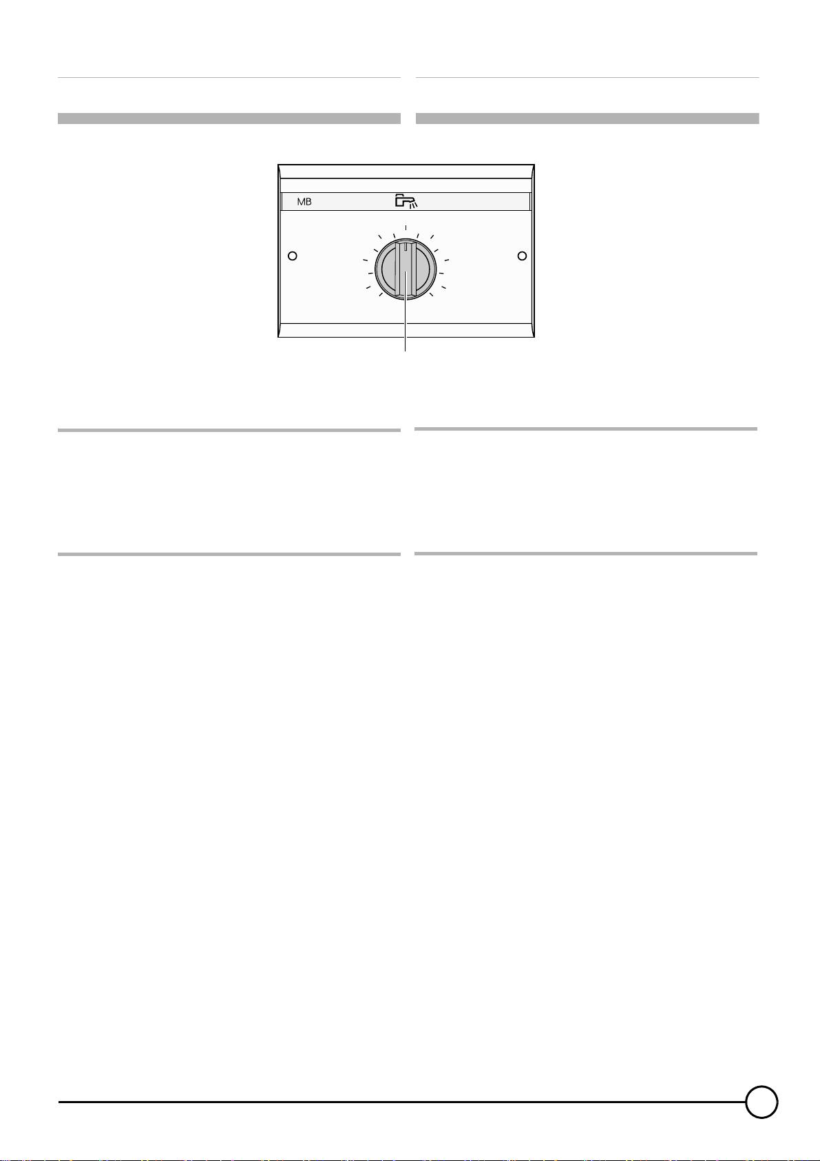
4.1 Réglage de la température de l'eau sanitaire
A : Réglage de la température moyenne de stockage de l'eau chaude
sanitaire de 10 à 80 °C.
Point dur à 60 °C (6)
4 Verwendung
5
6
7
8
81 11A80N 3
A
4.1 Einstellung der Warmwassertemperatur
A: Einstellung der Durchschnitts-Warmwassertemperatur im
Speicher von 10 bis 80 °C.
Druckpunkt bei 60 °C (6)
4.2 En cas d'absence prolongée (week-end,
vacances)
Protection antigel : Mettre le thermostat A sur la position 1 (environ
10 °C).
Voir "Pièces de rechange" : page 21.
Z
4.2 Im Falle längerer Abwesenheit (Wochende,
Urlaub)
Frostschutzfunktion: Thermostat A in Position 1 stellen (etwa 10 °C).
Siehe "Ersatzteilliste": Seite 21.
Z
25/08/09 - 94866509 - 8801-4297E AD128
5
Page 6
English
Nederlands
The MB2 module handles temperature regulation and domestic hot
water production priority.
1 Setting the load pump timer
Mini Maxi
T
SB
T=0
De module MB2 zorgt voor de regeling van de temperatuur en de
voorrang van de productie van sanitair warm water.
1 Instelling van de tijdvertraging van de
laadpomp
TEMPO
118A
L N
N8801
1
2
1. Timer activated
2. Timer setting deleted
3. Timer setting
The load pump timer setting enables load pump operation for 4
minutes (factory setting) after burner shutdown. This makes it
possible to use the residual heat accumulated in the heating body to
back up tank heating in summer.
The timer setting can be adjusted from 3 to 6 minutes using the
potentiometer located on the back of the appliance.
To delete the timer setting, move the bridge located on the back of the
appliance.
3
1. Tijdvertraging ingeschakeld
2. Tijdvertraging opgeheven
3. Instelling tijdvertraging
De tijdvertraging van de laadpomp laat de werking van de laadpomp
gedurende 4 minuten (standaard instelling) toe na uitschakeling van
de brander. Op die manier kan de in het verwarmingslichaam
opgehoopte restwarmte gebruikt worden ter aanvulling van het
opwarmen van de boiler in de zomer.
De tijdschakeling is in te stellen tussen 3 en 6 minuten, met behulp
van de potentiometer op de achterzijde van het apparaat.
Om de tijdvertraging op te heffen moet de brug op de achterzijde van
het apparaat verplaatst worden.
6
AD128 25/08/09 - 94866509 - 8801-4297E
Page 7
English
Nederlands
2 Setting the limiter thermostat
80°C
C
2 Instelling van de
begrenzingsthermostaat
90°C
30°C
80
°
C
3°
0
9
0
°
C
6
5
7
4
8
3
2
MB
1
8801N189B
A limiter thermostat set in the factory to 80°C limits the boiler
temperature during domestic charge.
The limiter thermostat can be adjusted from 30 to 90°C.
- Remove the module from the control panel if necessary.
- Pull the thermostat button out carefully (use pliers and a cloth).
- Remove the PCB.
- Set the limiter thermostat using a flat screwdriver.
- Fit the unit together.
Een in de fabriek op 80°C ingestelde thermostaat begrenst de
temperatuur van de ketel tijdens de sanitaire lading.
De begrenzingsthermostaat kan ingesteld worden tussen 30 en 90°C.
- Verwijder, indien nodig, de module van het bedieningspaneel.
- De thermostaatknop voorzichtig verwijderen door hem naar u toe te
trekken (gebruik eventueel een tang met een stofdoek).
- Verwijder de elektronische kaart.
- Stel de begrenzingsthermostaat af met behulp van een platte
schroevendraaier.
- Monteer het geheel opnieuw.
25/08/09 - 94866509 - 8801-4297E AD128
7
Page 8
English
Nederlands
3 Assembly and electrical connection
For example: DTG X / GSX N 100
Similar procedure for the other products.
1
DHW MODULE
MODULE E.C.S
BOILERVORRANGSCHALTUNG
M000292A
3
Insert the limiter thermostat bulb into the boiler sensor tube.
Connecting the tank sensor.
Insert the tank sensor bulb into the boiler sensor tube.
If the tank already has an adjustment thermostat:
- Remove the sensor from the thermostat.
- Install the new tank sensor, provided with option
In this scenario, the tank thermostat will no longer be used.
AD128
3 Montage en elektrische aansluiting
Voorbeeld: DTG X / GSX N 100
Zelfde soort procedure voor de andere producten.
2
4
6
5
7
4
8
3
2
MB
1
M000452-B
00045
M1A
Zet de bol van de begrenzingsthermometer op zijn plaats in de
dompelbuis van de ketel.
Aansluiting van de boilervoeler.
Zet de bol van de voeler van de boiler in de dompelbuis van de
boiler.
.
Indien de boiler al over een afstellingsthermostaat beschikt:
- Verwijder de voeler van de thermostaat.
- Zet de met de optie
AD128
meegeleverde nieuwe voeler van de
boiler op zijn plaats.
In dit geval wordt de thermostaat van de boiler niet meer gebruikt.
Valid only for DTG X / GSX N 100 boiler
- Put in place the cable clamp
and the 2 collars
provided with option AD128.
- Secure the tank sensor cable
using the traction clip and the
cable clips.
Connecting the load pump.
Separate the sensor cables from the 230 V cables. To
prevent interference, respect a minimum distance of 10 cm
between these.
8
Uitsluitend geldig voor de DTG X / GSX N 100 ketel
- Zet de kabelklem
optie AD128 meegeleverde beugels
op hun plaats.
en de 2 met
- Bevestig de kabel van de voeler van
de boiler met behulp van de
trekontlastingsbeugel en
kabelklemmen.
Aansluiting van de laadpomp.
Scheid de voelerkabels van de 230V kabels. Zorg, om
interferentie te voorkomen, voor een minimale afstand van
10 cm hier tussen.
AD128 25/08/09 - 94866509 - 8801-4297E
Page 9

English
Nederlands
4 Operating instructions
4
3
2
1
4.1 Setting the domestic water temperature
A: Regulating the storage temperature of domestic hot water between
10 and 80 °C.
Hard spot at 60°C (6)
4.2 In the event of prolonged absences (weekend,
holidays)
Antifreeze protection: Set the thermostat A to position 1 (around
10°C).
4Gebruik
5
6
7
8
81 11A80N 3
A
4.1 Afstelling van de temperatuur van het sanitaire
water
A: Afstelling van de gemiddelde temperatuur van de sanitair-
warmwatervoorraad tussen 10 en 80 °C.
Hard punt op 60°C (6)
4.2 Bij een langdurige afwezigheid (weekend,
vakantie)
Vorstbeveiliging: Zet de thermostaat A op stand 1 (ca. 10°C).
Please see "Spare parts": page 21.
Z
Zie "Reserveonderdelen": pagina 21.
Z
25/08/09 - 94866509 - 8801-4297E AD128
9
Page 10

Italiano
Español
Il modulo MB2 garantisce la regolazione della temperatura e la
priorità alla produzione dell'acqua calda sanitaria.
1 Regolazione della temporizzazione della
pompa di carico
Mini Maxi
T
SB
T=0
El módulo MB2 asegura la regulación de la temperatura y la prioridad
a la producción del agua caliente sanitaria.
1 Reglaje de la temporización de la bomba
de carga
TEMPO
118A
L N
N8801
1
2
1. Temporizzazione attivata
2. Temporizzazione eliminata
3. Regolazione temporizzazione
La temporizzazione della pompa di carico ne consente il
funzionamento per 4 minuti (regolazione di serie) dopo l'arresto del
bruciatore. Questo consente di utilizzare il calore residuo accumulato
nel corpo di riscaldamento per completare il riscaldamento del
bollitore in estate.
La temporizzazione è regolabile da 3 a 6 minuti con l'ausilio del
potenziometro collocato sul retro dell'apparecchio.
Per eliminare la temporizzazione, spostare il ponte collocato sul retro
dell'apparecchio.
3
1. Temporización activada
2. Temporización suprimida
3. Ajuste de la temporización
La temporización de la bomba de carga autoriza el funcionamiento de
la bomba de carga durante 4 minutos (ajuste de fábrica) después de
la parada del quemador. Esto permite utilizar el calor residual
acumulado en el cuerpo de la caldera para completar el
calentamiento del acumulador en verano.
La temporización es regulable de 3 a 6 minutoa mediante el
potenciómetro situado en la parte posterior del aparato.
Para suprimir la temporización, desplazar el puente situado en la
parte posterior del aparato.
10
AD128 25/08/09 - 94866509 - 8801-4297E
Page 11

Italiano
Español
2 Regolazione del termostato limitatore
80°C
3°
0
C
90°
C
°
C
2 Ajuste del termostato limitador
90°C
30°C
80
6
5
7
4
8
3
2
MB
1
8801N189B
Un termostato limitatore regolato di serie a 80°C limita la temperatura
della caldaia durante il carico sanitario.
Il termostato limitatore è regolabile da 30 a 90 °C.
- Rimuovere il modulo del pannello di comando, se necessario.
- Rimuovere il pulsante del termostato tirandolo verso di sè con
cautela (utilizzare una pinza e un panno).
- Rimuovere la scheda elettronica.
- Regolare il termostato limitatore con l'ausilio di un cacciavite piatto.
- Rimontare i pezzi.
Un termostato limitador ajustado en fábrica a 80ºC limita la
temperatura de la caldera durante la carga sanitaria.
El termostato limitador es ajustable de 30 a 90ºC.
- Retirar el módulo del cuadro de mando en caso necesario.
- Quitar el botón del termostato tirando con cuidado hacia afuera
(usar una pinza y un paño).
- Retirar la carta electrónica.
- Ajustar el termostato limitador con un destornillador plano.
- Volver a montar las piezas.
25/08/09 - 94866509 - 8801-4297E AD128
11
Page 12

Italiano
Español
3 Montaggio e collegamento elettrico
Esempio: DTG X / GSX N 100
Procedura simile per gli altri prodotti.
1
DHW MODULE
MODULE E.C.S
BOILERVORRANGSCHALTUNG
M000292A
3
Posizionare il bulbo del termostato limitatore nel pozzetto
portasonde della caldaia.
Collegamento della sonda bollitore.
Posizionare il bulbo della sonda bollitore nel pozzetto
portasonde del bollitore.
3 Montaje y conexión eléctrica
Ejemplo: DTG X / GSX N 100
Procedimiento similar para los otros productos.
2
4
6
5
7
4
8
3
2
MB
1
00045
M1A
Colocar el bulbo del termostato limitador dentro de la vaina de
la caldera.
Conexión de la sonda de acumulador.
Colocar el bulbo de la sonda del acumulador dentro de la vaina
del acumulador.
M000452-B
Se il bollitore possiede già un termostato di regolazione:
- Rimuovere la sonda del termostato.
- Posizionare la nuova sonda bollitore, fornita con l'opzione
AD128
.
In questo caso, il termostato del bollitore non sarà più utilizzato.
Solo valido per caldaia DTG X / GSX N 100
- Posizionare il ferma cavo
ed le 2 fascette forniti con
l'opzione AD128.
- Fissare il cavo della sonda del
bollitore a l'aiuto di clip della
trazione e dei ferma cavi.
Collegamento della pompa di carico.
Saparare i cavi sonda dai cavi 230 V. Per evitare
interferenze, mantenere una distanza minima di 10 cm tra i
suddetti fili.
Si el acumulador ya posee un termostato de regulación:
- Quitar la sonda del termostato.
- Colocar la nueva sonda del acumulador, suministrada con la
opción
AD128
.
En este caso, el termostato del acumulador ya no será utilizado.
Válido únicamente para caldera DTG X / GSX N 100
- Colocar el prensacable
abrazaderas
la opción AD128.
suministradas con
- Fijar el cable de la sonda del
acumulador con el tope de tracción y
los prensacables.
Conexión de la bomba de carga.
Separar los cables de sondas de los cables de 230 V. Para
evitar las interferencias, procure mantener una distancia de
al menos 10 cm entre ambos.
y las 2
12
AD128 25/08/09 - 94866509 - 8801-4297E
Page 13

Italiano
Español
4 Utilizzo
4
3
2
1
4.1 Regolazione della temperatura dell'acqua
sanitaria
A: Regolazione della temperatura media della riserva d'acqua calda
sanitaria da 10 a 80 °C.
Punto preimpostato a 60°C (6)
4.2 In caso di assenza prolungata (weekend,
vacanze)
Protezione antigelo: Mettere il termostato A sulla posizione 1 (circa
10 °C).
4 Utilización
5
6
7
8
81 11A80N 3
A
4.1 Ajuste de la temperatura del agua sanitaria
A: Ajuste de la temperatura media de almacenamiento del agua
caliente sanitaria de 10 a 80 °C.
Punto duro a 60 ºC (6)
4.2 En caso de ausencia prolongada (fin de
semana, vacaciones)
Protección antihielo: Ajustar el termostato A en la posición 1
(aproximadamente 10ºC).
Vedi "Pezzi di racambio": pagina 21.
Z
Véase "Piezas de recambio": página 21.
Z
25/08/09 - 94866509 - 8801-4297E AD128
13
Page 14

Polski
РУССКИЙ
Moduł priorytetu c.w.u. MB2 z ręczną regulacją temperatury.
1 Ustawienia wybiegu pomy ładującej
SB
T
Модуль MB2 обеспечивает регулирование температуры и
приоритет производства горячей санитарно-технической воды.
1 Регулировка временной задержки
загрузочного насоса
TEMPO
Mini Maxi
T=0
L N
118A
N8801
1
2
1. Wybieg włączony
2. Brak wybiegu
3. Nastawa czasu wybiegu
Pompa ładująca c.w.u. pracuje przez 4 minuty (nastawa fabryczna)
po wyłączeniu palnika. Taka nastawa pozwala przekazać ciepło
zgromadzone w korpusie kotła do zasobnika c.w.u..
Wybieg można nastawić w zakresie od 3 do 6 min. przy użyciu
potencjometru umieszczonego z tyłu modułu.
Aby wyłączyć wybieg pompy, należy zmienić ustawienie zworki
umieszczonej z tyłu modułu.
3
1. Временная задержка включена
2. Временная задержка выключена
3. Регулировка временной задержки
Временная задержка загрузочного насоса разрешает работу
загрузочного насоса в течение 4 минут (заводская настройка)
после выключения горелки. Это позволяет
использовать
остаточное тепло, аккумулированное в теплообменнике котла,
для завершения нагрева водонагревателя в летнем режиме.
Временная задержка регулируется от 3 до 6 минут при помощи
потенциометра, расположенного на задней стороне устройства.
Для выключения временной задержки переставить перемычку,
расположенную на задней стороне устройства.
14
AD128 25/08/09 - 94866509 - 8801-4297E
Page 15

Polski
РУССКИЙ
2 Nastawa czujnika temperatury
80°C
C
2 Регулировка ограничительного
термостата
90°C
30°C
80
°
C
3°
0
90°
C
6
5
7
4
8
3
2
MB
1
8801N189B
Temperatura kotła podczas pracy na potrzeby c.w.u. jest fabrycznie
ograniczona przez nastawę termostatu do 80°C.
Temperaturę kotła można regulować w zakresie od 30 do 90°C.
-Wyjąć moduł z konsoli sterowniczej jeśli jest to konieczne.
-Zdjąć z modułu ostrożnie do przodu pokrętło termostatu c.w.u. (dla
ochrony używać szczypiec i kawałka sukna).
-Odłączyć kable połączeniowe.
-Ustawić czujnik temperatury kotła wkrętakiem płaskim.
- Ponownie zmontować wszystkie elementy.
Ограничительный термостат с заводской настройкой 80 °С
ограничивает температуру котла во время нагрева санитарнотехнической воды.
Ограничительный термостат регулируется от 30 до 90 °С.
-
В случае необходимости вынуть модуль панели управления
котла.
- Снять ручку термостата, с осторожностью потянув ее на себя
(использовать пассатижи и тряпку).
- Вынуть электронную плату.
- Отрегулировать ограничительный термостат при помощи
плоской отвертки.
- Установить все детали на место.
25/08/09 - 94866509 - 8801-4297E AD128
15
Page 16

Polski
РУССКИЙ
3 Montaż i podłączenia elektryczne
Przykład: DTG X / GSX N 100
Podobna procedura jest dla innych kotłów.
1
DHW MODULE
MODULE E.C.S
BOILERVORRANGSCHALTUNG
M000292A
3
Umieść sondę termostatu w gilzie korpusu kotła..
Podłączenie czujnika temperatury podgrzewacza c.w.u..
Wprowadzić sondę czujnika podgrzewacza w gilzę
podgrzewacza c.w.u..
Jeżeli podgrzewacz c.w.u. ma już zamontowany inny regulator
temperatury:
- Zdemontować istniejący czujnik.
- Zamontować nowy czujnik podgrzewacza (dostarczony razem z
opcją
AD128
).
W takim przypadku regulator temperatury podgrzewacza nie jest
już używany.
3 Установка и электрическое
подключение
Пример : DTG X / GSX N 100
Похожая процедура для других котлов.
2
4
6
5
7
4
8
3
2
MB
1
00045
M1A
Установить колбу ограничительного термостата в
приемную гильзу котла.
Подключение датчика водонагревателя.
Установить колбу датчика водонагревателя в приемную
гильзу водонагревателя.
Если водонагреватель уже оснащен регулировочным
термостатом :
- Вынуть датчик термостата.
- Установить новый датчик водонагревателя, поставляемый с
дополнительным оборудованием
В этом случае термостат водонагревателя больше не будет
использоваться.
AD128
M000452-B
.
Dotyczy tylko kotła DTG X / GSX N 100
- Zamontować uchwyt kablowy
i 2 opaski dostarczone
w opcji AD128.
- Kabel czujnika podgrzewacza
przymocować uchwytem
kablowym z odpowiednim
odciążeniem.
Podłączanie pompy ładowania zasobnika.
Kable czujników oraz pod napięciem 230V muszą być
oddzielone od siebie. Dla uniknięcia zakłóceń zachować
pomiędzy nimi minimalną odległość 10 cm.
16
Действительно только для котла DTG X / GSX N 100
- Установить фиксирующую
защелку, препятствующую
вытягиванию
зажима
дополнительным оборудованием
и 2 кабельных
, поставляемых с
AD128.
- Закрепить кабель датчика
водонагревателя при помощи
фиксирующей защелки,
препятствующей вытягиванию и
кабельных зажимов.
Подключение загрузочного насоса.
Отделить кабели датчиков от кабелей 230 В. Для
предотвращения помех соблюдайте между ними
минимальное расстояние 10.
AD128 25/08/09 - 94866509 - 8801-4297E
Page 17

Polski
РУССКИЙ
4 Zastosowanie
3
2
1
4.1 Ustawienie temperatury c.w.u.
A: Zakres nastawy średniej temperatury wody w podgrzewaczu od 10
do 80 °C.
Punkt oporu - 60 °C (6)
4.2 W przypadku dłuższej nieobecności (weekend,
wakacje)
Ochrona przeciwzamrożeniowa: Ustawić termostat A w pozycji 1
(około 10°C).
4 Эксплуатация
5
4
6
7
8
81 11A80N 3
A
4.1 Регулировка температуры горячей
санитарно-технической воды
A : Регулировка средней температуры хранения горячей
санитарно-технической воды в диапазоне от 10 до 80 °C.
Жесткая точка на 60 °С (6)
4.2 В случае длительного отсутствия (уик-энд,
отпуск)
Защита от замораживания : Установить термостат A в
положение 1 (приблизительно 10 °С).
Patrz "Lista części zamiennych": strona 21.
Z
См. перечень запасных частей : Страница 21.
Z
25/08/09 - 94866509 - 8801-4297E AD128
17
Page 18

中文
MB2 生活热水优先模块可以调节生活热水的温度 , 并优先生产生活热水 .
1 调节泵的延时
SB
1
2
T
TEMPO
Mini Maxi
T=0
2 调节温控开关的温度限制器
90°C
80°C
8A
L N
N8801 11
C
3
30°C
80
°
C
3°
0
9
0
°
C
6
5
7
4
8
3
2
MB
1
8801N189B
1. 延时开关位置
2. 取消延时
3. 调节延时
换热泵的延时可以使换热泵在燃烧机停止后仍然工作 4 分
钟 ( 工厂调节 ). 这样可以将炉体内剩余的热量带到水箱中
去 , 在夏天起到加热水箱保护炉体的目的 .
可以通过调节旁边的电位计来调节泵的延时由3 到6 分钟 .
取消延时将延时开关的位置移动到如图 1 所示 .
在工厂内限温开关已经调节在80°C,它可以根据生活热水
的最大温度标准限制锅炉的温度 .
限温开关调节在 30 到 90°C.
- 如需要的话卸下锅炉的控制面板 .
- 小心的将温控器的旋钮抽出 ( 用布垫住并用钳子拉出 ).
- 卸下电路板 .
- 用一字改锥调整限温开关 .
- 重新安装时 .
18
AD128 25/08/09 - 94866509 - 8801-4297E
Page 19

中文
3 安装及电路连接
例如 : DTG X / GSX N 100
安装在其他德地氏产品上的程序类似 .
1
DHW MODULE
MODULE E.C.S
BOILERVORRANGSCHALTUNG
M000292A
2
4
6
5
7
3
MB
00045
M1A
4
8
3
2
1
M000452-B
将温度限制温控开关的传感器插入锅炉的套管内 .
连接水箱温度传感器 .
将水箱传感器插入水箱的套管内 .
如果水箱本身带有温度调节开关 :
-
将旧的温控开关传感器拔出 .
-
安装新的水箱传感器 , 由附件
AD128
一同提供 .
这种情况下 , 水箱本身的温控开关将不再起作用 .
只针对 DTG X / GSX N 100 型锅炉的操作
- 安装线卡
以及2个固定线圈 ,这些都随附件AD128提
供.
- 用线卡及拉带固定水箱温度传感器的线缆 .
连接换热泵 .
传感器的电缆与 230V 电缆必须分开放置 . 两者之间的距离至少要大于 10 毫米 .
25/08/09 - 94866509 - 8801-4297E AD128
19
Page 20

中文
4 使用
5
4
3
6
2
1
7
8
81 11A80N 3
A
4.1 调节生活热水温度和停止生产生活热水
A: 调节存储生活热水的平均温度 , 可在 10 至 80 °C 之间调节 .
生活热水的温度最好控制在 60 °C (6)
4.2 在长时间离开的情况下 ( 周末 , 假期 )
防冻保护 : 将温控开关 A 调节到 1 的位置 ( 大约 10 °C).
见配件表 : 21 页.
Z
20
AD128 25/08/09 - 94866509 - 8801-4297E
Page 21

Français
Deutsch
5 Pièces de rechange - AD128
25/08/09
Pour commander une pièce de rechange, indiquer le numéro de
référence figurant dans la liste
11
5
9
10
4
2
5 Ersatzteile - AD128
25/08/09
Bei Bestellung der Ersatzteile, ist es unbedingt nötig die ArtikelNummer des gewünschten Ersatzteils anzugeben
7
7
8
8
BM
2
1
6
5
7
4
8
3
2
1
6
Rep. Code DD Code OE Désignation
1 97525343 Façade
2 200000461 Fixation
3 88015500 180118 Bouton de réglage + Ergot
4 88055599 124568 Carte MB2
5 88014711 706105
6 95365489 120744 Sonde ballon - KVT40 - 5 m
7 95320819 Support supérieur carte
8 95320820 Support inférieur carte
9 95320187 Serre câble
10 95320780 126584 Collier
11 96550353 Entretoise
Thermostat limiteur 80 °C + Etrier de
fixation
D7
8
81N011
3
Nr. Artikel DD Artikel OE Bezeichnung
1 97525343 Frontabdeckung
2 200000461 Halterung
3 88015500 180118 Einstellknopf + Anstoß
4 88055599 124568 Leiterplatte MB2
5 88014711 706105
6 95365489 120744 Speicherfühler - KVT40 - 5 m
7 95320819 Oberer Leiterplattenträger
8 95320820 Unterer Leiterplattenträger
9 95320187 Kabelklemme
10 95320780 126584 Schlauchschelle
11 96550353 Eckverbinder
Sicherheitstemperaturwächter 80 °C +
Befestigungsbügel
25/08/09 - 94866509 - 8801-4297E AD128
21
Page 22

English
Nederlands
5 Spare parts - AD128
25/08/09
To order a spare part, give the reference number shown on the list
Code no. DDCode no.
Ref.
1 97525343 Front panel
2 200000461 Attachment
3 88015500 180118 Setting button + Pin
4 88055599 124568 Card MB2
5 88014711 706105 80°C limiter thermostat + Fastening clamp
6 95365489 120744 Tank sensor - KVT40 - 5 m
7 95320819 Upper card support
8 95320820 Lower card support
9 95320187 Cable clamp
10 95320780 126584 Clamp
11 96550353 Spacer
OE
Description
5 Reserveonderdelen - AD128
25/08/09
Bij bestelling van een onderdeel, moet u het codenummer opgeven
dat in de lijst staat naast het volgnummer van het gewenste
onderdelen
Artikelnr. DDArtikelnr.
Kent.
1 97525343 Voorzijde
2 200000461 Bevestiging
3 88015500 180118 Regelknop + Stift
4 88055599 124568 Kaart MB2
5 88014711 706105
6 95365489 120744 Boilervoeler - KVT40 - 5 m
7 95320819 Bovenste kaarthouder
8 95320820 Onderste kaarthouder
9 95320187 Kabelsluiting
10 95320780 126584 Klemring
11 96550353 Dwarsstang
OE
Begrenzingsthermostaat 80 °C +
Befestigingsbeugel
Benaming
Italiano
5 Pezzi di ricambio - AD128
25/08/09
Per ordinare un pezzo di ricambio, è indispensabile citare il numero di
codice indicato nella lista
标号 编号 DD 编号 OE 名称
1 97525343
2 200000461
3 88015500 180118
4 88055599 124568
5 88014711 706105
6 95365489 120744
7 95320819
8 95320820
9 95320187
10 95320780 126584
11 96550353
面板
固定件
调节按钮 + 固定销
MB2 电路板
温度限制调温器 80 °C + 固定卡
水箱温度传感器 - KVT40 - 5 m
上部固定销
下部固定销
线卡
线缆固定环
垫片
Español
5 Piezas de recambio - AD128
25/08/09
Para pedir una pieza de recambio, debe indicarse necesariamente el
número de código que figura en la lista, frente a la referencia de la
pieza deseada
Ref. Código DD Código OE Descripción
1 97525343 Frontal
2 200000461 Fijación
3 88015500 180118 Botón de ajuste + Patilla
4 88055599 124568 Carta MB2
5 88014711 706105
6 95365489 120744 Sonda acumulador - KVT40 - 5 m
7 95320819 Soporte superior carta
8 95320820 Soporte inferior carta
9 95320187 Sujetacables
10 95320780 126584 Abrazadera
11 96550353 Separador
Termostato limitador 80 °C + Abrazadera
de fijación
22
AD128 25/08/09 - 94866509 - 8801-4297E
Page 23

Polski
РУССКИЙ
5Części zamienne - AD128
25/08/09
Przy zamawianiu części zamiennych należy koniecznie podać numer
artykułu żądanej części
Poz. Kod DD Kod OE Opis
1 97525343 Pokrywa czołowa
2 200000461 Mocowanie
3 88015500 180118 Pokrętło nastawy + blokada
4 88055599 124568 Karta MB2
5 88014711 706105
6 95365489 120744 Czujnik podgrzewacza - KVT40 - 5 m
7 95320819 Wsporniki górne
8 95320820 Wspornik dolny
9 95320187 Zacisk kablowy
10 95320780 126584 Opaska zaciskowa
11 96550353 Złącze narożne
Termostat bezpieczeństwa 80°C +
Kątownik mocujący
5 Запасные части - AD128
25/08/09
Для заказа запасной части указать номер артикула, приведенный
в перечне
Поз. Код DD Код OE Обозначение
1 97525343 Передняя часть
2 200000461 Крепление
3 88015500 180118 Ручка регулировки + Упор
4 88055599 124568 Плата MB2
5 88014711 706105
6 95365489 120744 Датчик водонагревателя - KVT40 - 5 м
7 95320819 Верхняя опора платы
8 95320820 Нижняя опора платы
9 95320187 Зажим для кабеля
10 95320780 126584 Хомут
11 96550353 Распорка
Ограничительный термостат 80 °С +
Крепежная скоба
中文
5 配件 - AD128
25/08/09
在订购配件时 , 请在订单上标出您所需配件的订货号
标号 编号 DD 编号 OE 名称
1 97525343
2 200000461
3 88015500 180118
4 88055599 124568
5 88014711 706105
6 95365489 120744
7 95320819
8 95320820
9 95320187
10 95320780 126584
11 96550353
面板
固定件
调节按钮 + 固定销
MB2 电路板
温度限制调温器 80 °C + 固定卡
水箱温度传感器 - KVT40 - 5 m
上部固定销
下部固定销
线卡
线缆固定环
垫片
25/08/09 - 94866509 - 8801-4297E AD128
23
Page 24

25/08/09
DE DIETRICH THERMIQUE
57, rue de la Gare F- 67580 MERTZWILLER - BP 30
www.dedietrich-heating.com
AD051-AA
94866509
 Loading...