

Page 1
EN
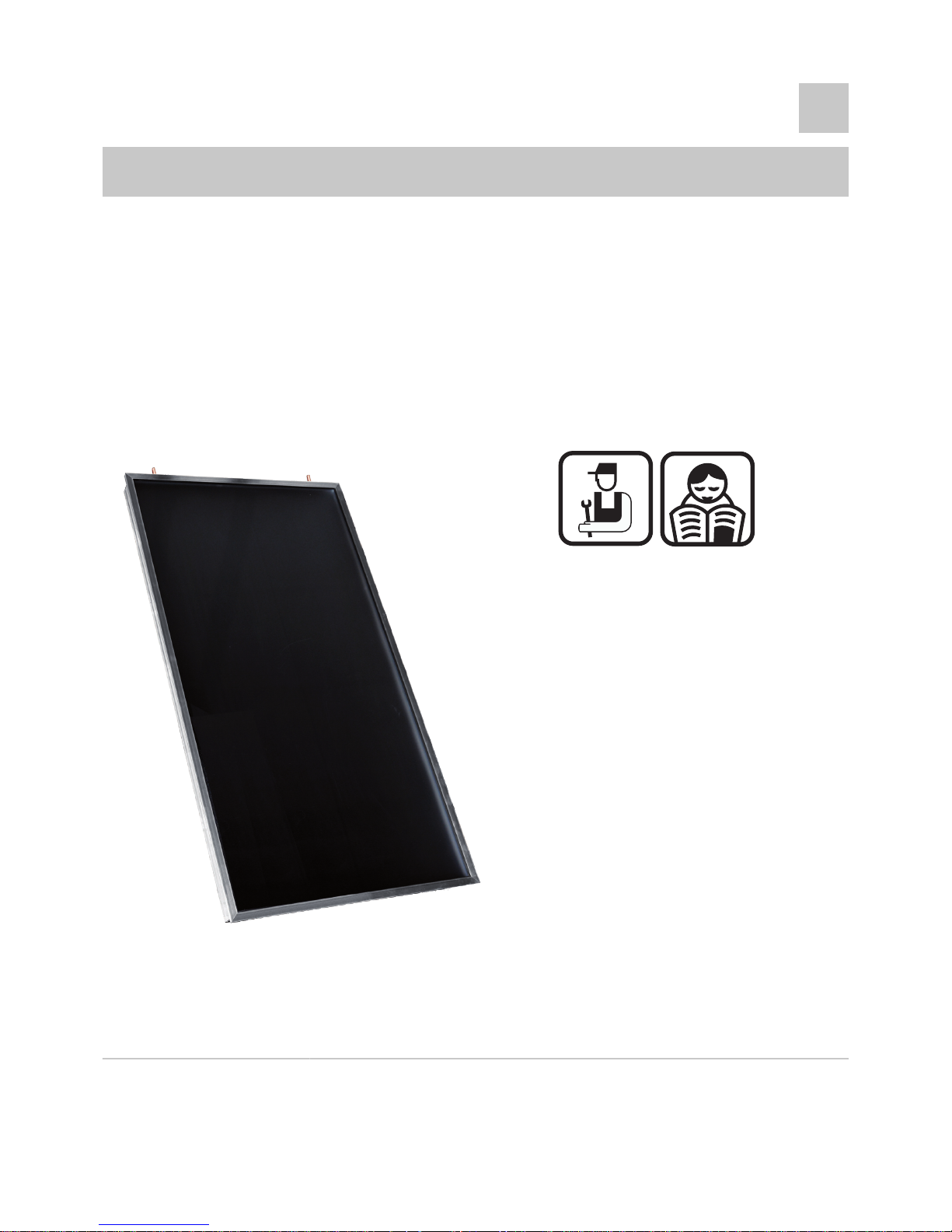
Flat solar panels
NEO 2.1 / SUN 211
Installation, User
and Service
Manual
Roof-Surface
Installation
Terrace mounting
300020210-001-B
Page 2

Contents
1 Introduction ................................................................................................4
1.1 Used symbols .......................................................4
1.2 General ..................................................................4
1.2.1 Manufacturer's liability .............................................4
1.2.2 Installer's liability .....................................................5
2 Safety instructions and recommendations ..............................................6
2.1 Safety instructions ...............................................6
2.2 Recommendations ................................................6
3 Description ..................................................................................................8
3.1 Operating principle ...............................................8
3.2 Technical characteristics .....................................8
4 Installation ..................................................................................................9
4.1 Regulations governing installation .....................9
4.1.1 All installation system ..............................................9
4.1.2 Roof-Surface Installation .........................................9
4.1.3 Terrace mounting ..................................................10
4.2 Package list .........................................................11
4.2.1 Package for an assembly on the roof ....................11
4.2.2 Anchorage fittings for roof mounting .....................12
4.2.3 Terrace assembly kit .............................................13
4.3 Main dimensions .................................................14
4.4 Installation diagrams ..........................................15
4.5 Assembling the solar collectors .......................17
4.5.1 Warning .................................................................17
4.5.2 Tools required .......................................................18
4.5.3 Dimensions ...........................................................18
4.5.4 Fitting the hooks ....................................................20
4.5.5 Vertical assembly, juxtaposed ...............................23
4.5.6 Horizontal assembly, superposed (only on
roof) .......................................................................29
1
05/10/09 - 300020210-001-B
Page 3

4.6 Solar collector temperature sensor ..................35
4.7 Passing Pipes and Cable through the
Roof ......................................................................36
4.8 Hydraulic connections .......................................37
4.8.1 Connection dimensions .........................................37
4.8.2 Connecting ............................................................37
4.8.3 Pipe insulation .......................................................38
4.9 Filling the system ...............................................38
5 Commissioning ........................................................................................40
5.1 Check points before commissioning ................40
5.2 Commissioning ...................................................40
6 Checking and maintenance .....................................................................41
6.1 General instructions ...........................................41
7 Warranty ....................................................................................................42
7.1 General ................................................................42
7.2 Warranty terms ...................................................42
Contents NEO 2.1 / SUN 211
2
05/10/09 - 300020210-001-B
Page 4

3
05/10/09 - 300020210-001-B
Page 5
1 Introduction
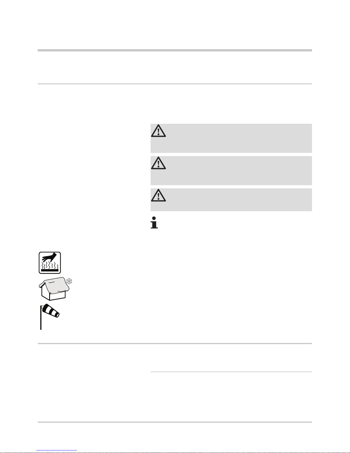
1.1 Used symbols
In these instructions, various danger levels are employed to draw the
user's attention to particular information. In so doing, we wish to
safeguard the user's safety, obviate hazards and guarantee correct
operation of the appliance.
DANGER
Risk of a dangerous situation causing serious physical
injury.
WARNING
Risk of a dangerous situation causing slight physical
injury.
CAUTION
Risk of material damage.
Signals important information.
¼ Signals a referral to other instructions or other pages in the
instructions.
Caution: Risk of being burnt.
Zone susceptible to snow.
Zone susceptible to windy conditions.
1.2 General
1.2.1. Manufacturer's liability
Our products are manufactured in compliance with the essential
requirements of the various Directives applicable. They are therefore
delivered with [ marking and all relevant documentation.
NEO 2.1 / SUN 211
1. Introduction
05/10/09 - 300020210-001-B
4
Page 6

In the interest of customers, we are continuously endeavouring to
make improvements in product quality. All the specifications stated in
this document are therefore subject to change without notice.
Our liability as the manufacturer may not be invoked in the following
cases:
4 Incorrect use of the appliance.
4 Faulty or insufficient maintenance of the appliance.
4 Incorrect installation of the appliance.
1.2.2. Installer's liability
The installer is responsible for the installation and inital start up of the
appliance. The installer must respect the following instructions:
4 Read and follow the instructions given in the manuals provided
with the appliance.
4 Carry out installation in compliance with the prevailing legislation
and standards.
4 Perform the initial start up and carry out any checks necessary.
4 Explain the installation to the user.
4 Warn the user of the obligation to check the appliance and
maintain it in good working order.
4 Give all the instruction manuals to the user.
1. Introduction NEO 2.1 / SUN 211
5
05/10/09 - 300020210-001-B
Page 7
2 Safety instructions and
recommendations
2.1 Safety instructions
DANGER
The permissible roof load of the building must not at any
time be exceeded. If necessary, a structural engineer
should be consulted before commencing work.
WARNING
All electrical work must be carried out by a qualified
electrician and must conform to the applicable standards,
specifications, safety regulations and the requirements of
the local electricity supplier.
CAUTION
Do not neglect to service the appliance. Contact a qualified
professional or take out a maintenance contract for the
annual servicing of the appliance.
2.2 Recommendations
WARNING
4 Any operation on the installation must be performed
by a qualified technician respecting professional
regulations and in accordance with this document.
4 When making the connections, it is imperative that
the standards and corresponding local directives are
respected.
4 The flat solar panels and fittings should be handled carefully during
transportation and storage. If the packing has nevertheless been
damaged during transit, the damage must be reported
immediately to and claimed against the carrier.
4 The contents of the assembly kit must be checked before
installation against the list which accompnaies each kit.
4 When installing the panels, take note of the safety instructions in
this document.
4 The packing material should be properly disposed of after
installation.
4 Insulate the pipes in rooms that are not heated (cellars and lofts).
4 Check regularly that the installation contains water and is
pressurised.
NEO 2.1 / SUN 211
2. Safety instructions and recommendations
05/10/09 - 300020210-001-B
6
Page 8

4 Service the appliance regularly to ensure that it operates correctly.
2. Safety instructions and recommendations NEO 2.1 / SUN 211
7
05/10/09 - 300020210-001-B
Page 9
3 Description
3.1 Operating principle
The short-wave solar radiation (sunlight) striking the solar panel is
converted into heat by the selective coating on the absorber. From
there it is transferred by heat conduction to the absorber pipe and
carried by the heat-transporting fluid to the calorifier. The solar-panel
fluid heats the calorifier by means of the energy absorbed from the
sun and cools down itself in the process.. The cooled heattransporting fluid then flows back to the solar panel in order to collect
more solar energy. An intelligent control system ensures that the
circulation system is only active when there is sufficient solar
radiation, thus optimising the collection of solar energy.
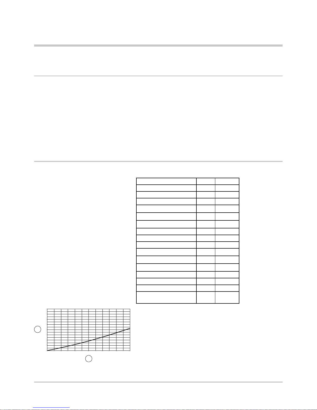
3.2 Technical characteristics
Length mm 1960
Width mm 1060
Height mm 70
Weight kg 34.45
Gross collector area A
G
m
2
2,1
Inlet surface Aa
m
2
1,88
Absorber surface A
A
m
2
1,90
Water content litres 1,2
Maximum operating pressure bar 10
Testing pressure bar 15
Optical efficiency η
o
0,773
Loss rating a
1
W/m2.K
3,676
Loss rating a
2
W/m2.K
0,0143
Stagnation temperature °C 180
Hydraulic connections mm 12
Pressure drop mbar See below
Fitted tilt angle
minimum/maximum
° 20 to 65
Load loss curve
A
Pressure drop (mbar)
Z
Mass flow (Kg/h)
0
50
100
150
200
250
300
350
400
0 50 100 150 200 250 300
1
2
M002031-A
NEO 2.1 / SUN 211 3. Description
05/10/09 - 300020210-001-B
8
Page 10
4 Installation
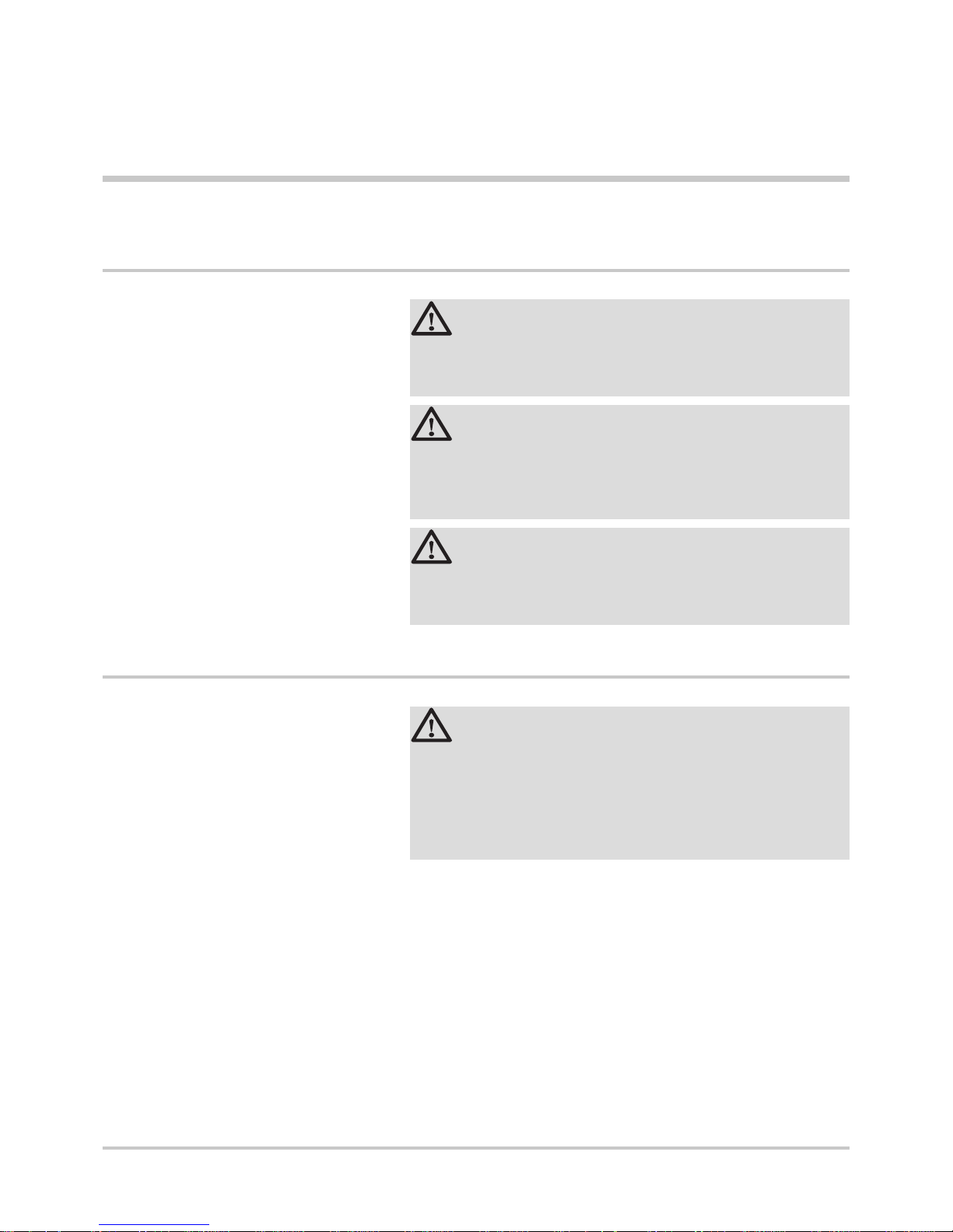
4.1 Regulations governing installation
4.1.1. All installation system
CAUTION
4 The installation and maintenance of the appliance
must be carried out by a qualified professional in
compliance with the statutory texts of the codes of
conduct in force.
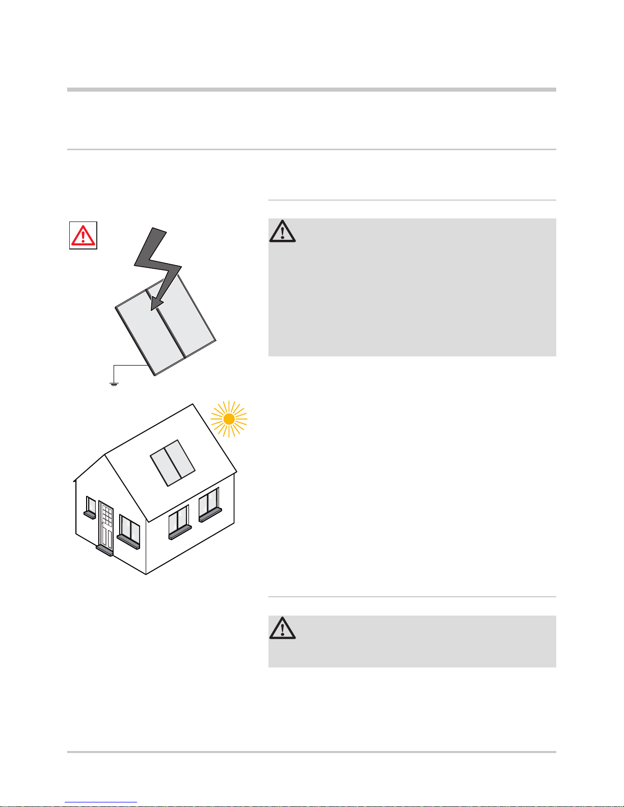
4 Solar installations must be earthed to protect them
against lightning.
4 Protection of the environment: Place a container of
sufficient volume under the drain pipe and the valve
discharge pipe.
4 The installation should therefore not be flushed or filled when the
collectors are hot (in strong sunshine).
4 The solar system must at all times be filled with : heat transporting
fluidTyfocor L or LS.
4.1.2. Roof-Surface Installation
CAUTION
Before installation, make sure that the framework is solid
and strong enough to comply with the static requirements.
4 The roof-integral installation set is designed specifically as a
mounting system for the NEO 2.1 / SUN 211 flat solar panels and
may only be used in accordance with their building regulations
approval.
M001788-A
M001707-A
4. Installation
NEO 2.1 / SUN 211
9
05/10/09 - 300020210-001-B
Page 11
4 The installation set is designed for rooves with standard roof
tiles. If the roof in which the panels are to be fitted has particularly
high roof tiles, please consult your specialist advisor.
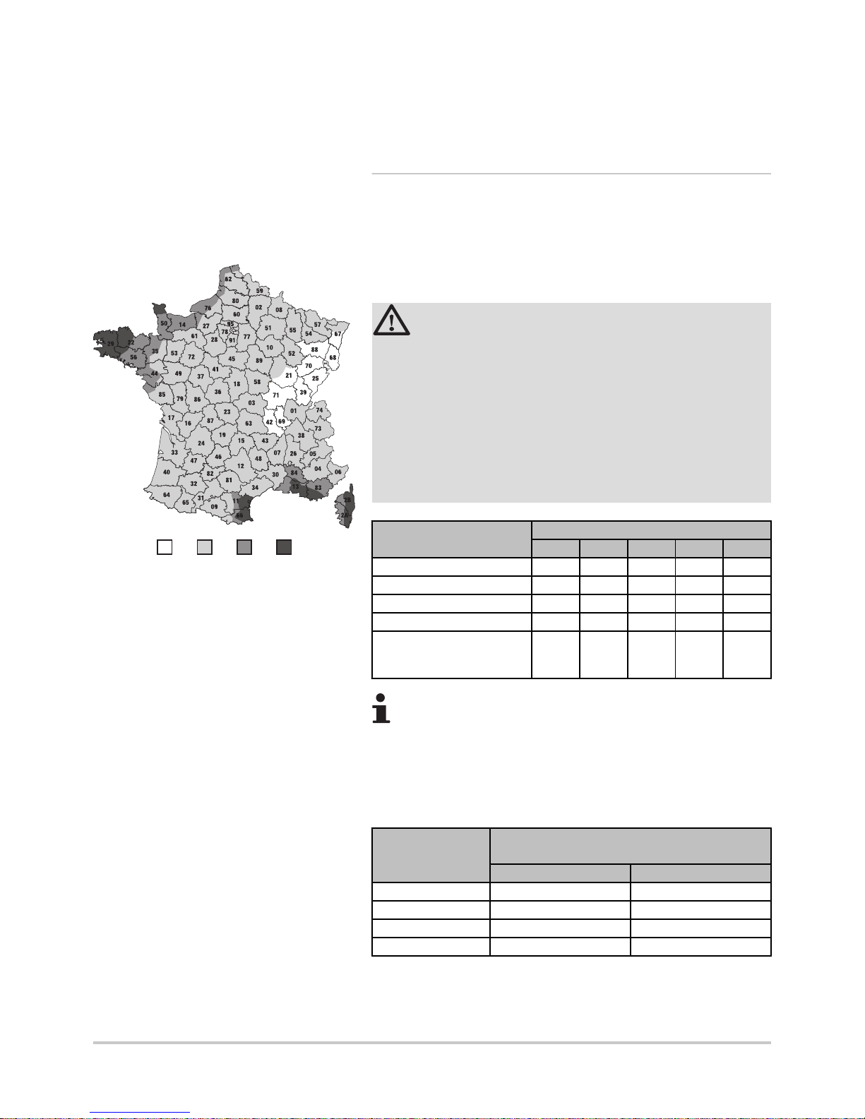
4.1.3. Terrace mounting
n
Ballast per solar panel (kg)
Rules NV65 (DTU P06-002, April 2000): Calculation rules defining the
effects of snow and wind on buildings.
CAUTION
If the assembly's supporting frame is not screwed to the
building, it must be weighted down according to the
technical guidance. Kerb stones (100 x 250 x 080), for
example, are suitable for weighting down. Stones must be
slid in and set in between the T frames. Position the ballast
stones before the finally attaching the inner screws and
the cross.
At no time should the maximum authorised load be
exceeded. If necessary, a structural engineer should be
consulted before commencing work.
Building height (m) Ballast per solar panel (kg)
Zone 1 Zone 2 Zone 3 Zone 4 Zone 5
< 10 140 170 210 255 340
10 to 20 170 200 250 300 405
20 to 30 190 230 285 340 455
30 to 40 205 245 310 370 495
Increase coefficient for
exposed sites (shoreline,
hilltops, narrow valleys, etc.)
1.35 1.3 1.25 1.2 1.2
The values indicated in the "Zone 5" column in the table
are valid for the Outre-Mer regions.
n
Pull-out resistance of the screws holding the supports
in place
Building height (m)
Panel holding resistance in terms of panel slope
(N/m2)
60° 45°
< 10 4400 3400
10 to 20 5200 4300
20 to 30 5900 4800
30 to 40 6400 5200
1
2
3
4
M001772-A
NEO 2.1 / SUN 211 4. Installation
05/10/09 - 300020210-001-B
10
Page 12
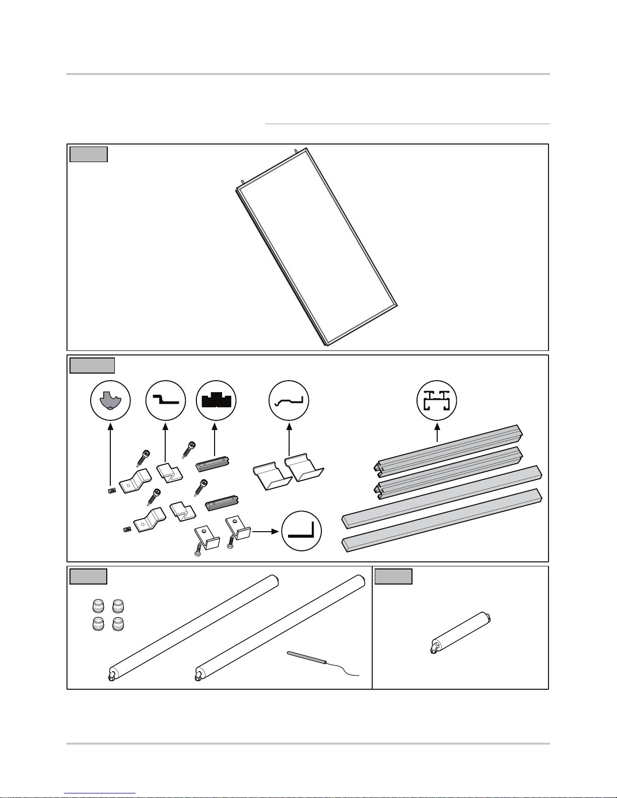
4.2 Package list
4.2.1. Package for an assembly on the roof
M001749-A
ER45
M001750-A
EG450
M001751-A
ER67 ER69
4. Installation NEO 2.1 / SUN 211
11
05/10/09 - 300020210-001-B
Page 13
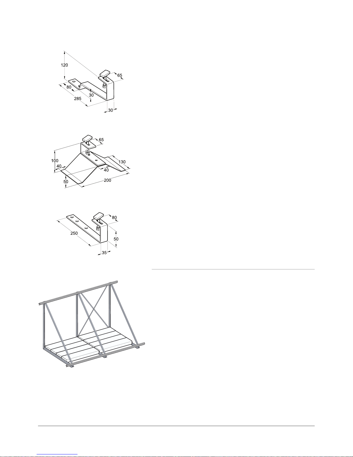
4.2.2. Anchorage fittings for roof mounting
The roof anchors are not included in the roof-surface
installation set and must be ordered separately.
CAUTION
Before installation, make sure that the framework is solid
and strong enough to comply with the static requirements.
There are different types of roof anchor available:
4 Aluminium roof anchors for assembly independent of the
chevrons.
4 Rafter-mounted anchors.
4 Hooks to be fitted to the roof covering.
In the first case, additional mounting battens have to be added to the
roof structure. In order to fit the mounting battens to the framework of
a finished roof, the roof tiles covering the entire length of the mounting
battens have to be moved out of the way. The roof anchors are then
located on the battens and fixed.
With the rafter-mounted type, only individual tiles above the fixing
points on the rafters have to be removed. The roof anchors are
screwed to the rafters thus exposed. Afterwards, the tiles are replaced
and the roof is immediately waterproof again. The installation of the
panel-mounting system can start.
If installing on metal rooves, the roof anchors must be ordered from
the manufacturer of the roof system concerned.
The hoses of the solar-panel connection sets can be passed through
the roof by feeding them through a vented roof tile.
n
Aluminium roof anchor for long-stringed gutter tile
EG 311 (4 pieces)
EG 312 (6 pieces)
On tiled rooves, additional mounting battens are added to the roof
substructure.
Charateristics of the assembly plates:
4 Cross section: 30 x 90 mm
4 Length: Width of the bank of solar collectors
4 The ends must rest on a chevron
The roof anchors are fixed to these assembly planks (assembly
independent of the chevrons).
n
Stainless steel roof anchor for long-stringed gutter tile
EG 313 (4 pieces)
EG 314 (6 pieces)
These roof anchors are attached directly to the roof rafters (rafter-
mounted anchors).
M001741-A
M001742-A
<100
NEO 2.1 / SUN 211
4. Installation
05/10/09 - 300020210-001-B
12
Page 14
n
Stainless steel roof anchor for flat tiles
EG 315 (4 pieces)
EG 316 (6 pieces)
These roof anchors are attached directly to the roof rafters (rafter-
mounted anchors). Their slim design normally allows two roof
anchors to be fixed to one rafter.
n
Stainless steel roof anchor for corrugated rooves
EG 317 (4 pieces)
EG 318 (6 pieces)
On corrugated rooves (fibrecement, asbestos, etc.) these roof
anchors are screwed to the roof rafters through the corrugated sheets
(rafter-mounted anchors). They are fixed by coach bolts (not
supplied with the roof anchors as they vary depending on the roofing
manufacturer).
n
Stainless steel roof anchor for slate
EG 319 (4 pieces)
EG 320 (6 pieces)
These roof anchors are screwed to the rafters through the boarding
(rafter-mounted anchors). The roof anchor then has to be covered
in the normal way.
4.2.3. Terrace assembly kit
For terrace assembly, specific kits are available: EG 358, EG 359.
Refer to the instructions delivered with the package.
M001743-A
M001744-A
M001745-A
M001747-A
4. Installation NEO 2.1 / SUN 211
13
05/10/09 - 300020210-001-B
Page 15

4.3 Main dimensions
A
Solar collector inlet
Z
Solar collector outlet
E
Solar sensor probe
M001740-A
1060
113,5 113,5
175,5
371960
70
3
2
1 2 31
NEO 2.1 / SUN 211 4. Installation
05/10/09 - 300020210-001-B
14
Page 16

4.4 Installation diagrams
4 Vertical assembly, juxtaposed.
Connection for 2 to 5 collectors.
CAUTION
Place the collector sensor on the flow side of the solar
circuit (flow from the hottest collector).
A: Solar sensor probe.
4
Horizontal assembly, superposed (only on roof).
Connection for 2 to 5 collectors.
M001775-B
A
M001754-B
A
M001776-A
A
A
4. Installation NEO 2.1 / SUN 211
15
05/10/09 - 300020210-001-B
Page 17

4 Example of an installation
4
Pressure gauge
9
Isolating valve
17
Drain cock
56
Domestic hot water circulation loop return
57
Domestic hot water outlet
61
Thermometer
84
Stop valve with lockable nonreturn valve
85
Primary solar circuit pump
87
6-bar calibrated and sealed safety valve (primary solar)
88
Expansion vessel
89
Heat transfer fluid container
109
Domestic hot water thermostatic mixing valve
112a
Solar sensor probe
112b
Domestic hot water sensor
114
Solar circuit drainage valve
126
Solar regulator
129
Duo-Tube
130
Manual bleed degasser
131
Flat or tubular solar panel
M001773-A
130
89
230V
50Hz
114
61
88
87
85
4
84
114
NEO 2.1 / SUN 211 4. Installation
05/10/09 - 300020210-001-B
16
Page 18

4.5 Assembling the solar collectors
4.5.1. Warning
M001748-A
4. Installation NEO 2.1 / SUN 211
17
05/10/09 - 300020210-001-B
Page 19

4.5.2. Tools required
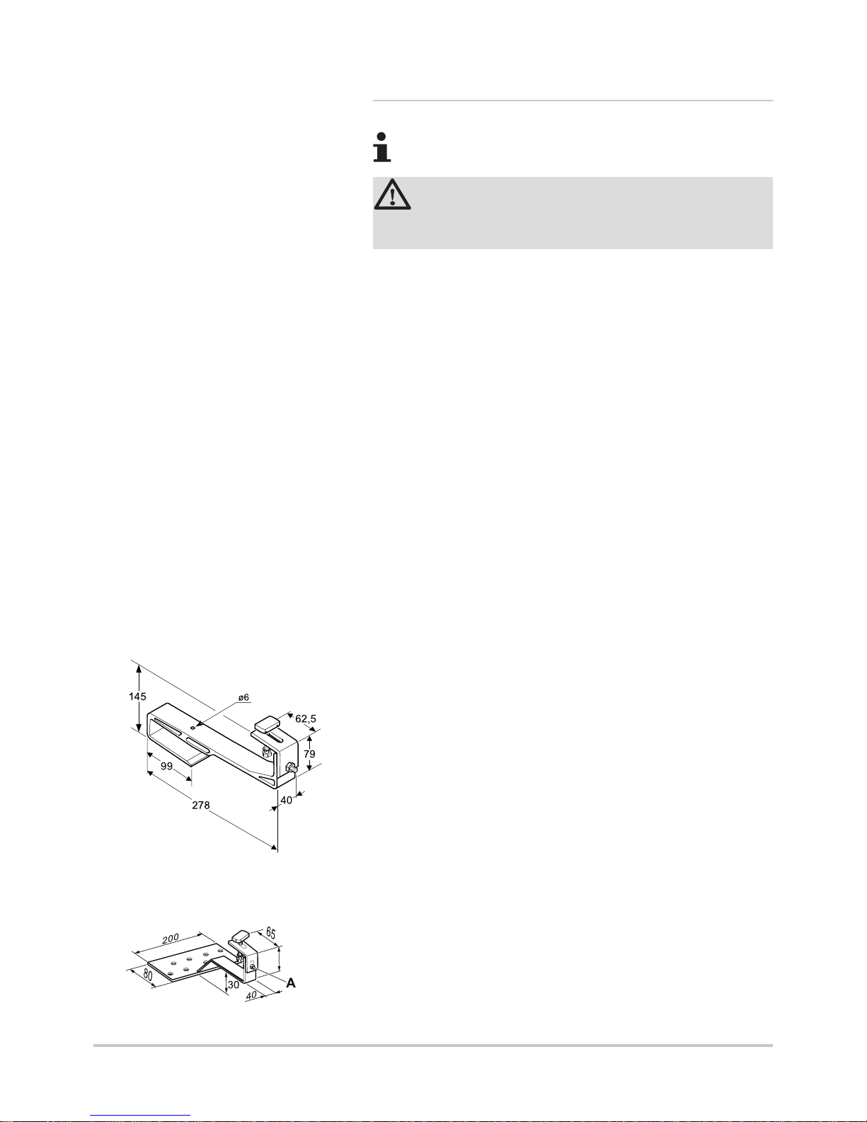
4.5.3. Dimensions
Side
A B C D
E
(1)F(1)G(1)H(1)I(1)
Dimensions
(mm)
1960 <
250
1400 to
1700
60 1100 2204 3306 4408 5510
(1) Minimum length of the mounting rails
4 To install a large number of solar collectors, it is sufficient to place
side-by-side or to superimpose the configurations described in this
chapter.
4 You will need 4 hooks (adapted to the roof covering) to fit the first
battery sensor and 2 hooks for each additional sensor.
4 Fitting on hooks: If the gap between the chevrons makes it
impossible to respect dimension B at both extremities of the bank
of solar collectors, 2 additional roof anchors are required.
M001753-A
M001752-A
I
NEO 2.1 / SUN 211 4. Installation
05/10/09 - 300020210-001-B
18
Page 20

M001777-A
I
M001778-A
4. Installation NEO 2.1 / SUN 211
19
05/10/09 - 300020210-001-B
Page 21

4.5.4. Fitting the hooks
n
Assembly of the roof anchors independently of the
chevrons
1
2
M001757-A
NEO 2.1 / SUN 211 4. Installation
05/10/09 - 300020210-001-B
20
Page 22

¼ Dimensions a - b, see chapter "Dimensions", page 18
3
M001758-A
M001759-A
4. Installation NEO 2.1 / SUN 211
21
05/10/09 - 300020210-001-B
Page 23

n
Fitting the hooks to the chevrons
¼ Dimensions a - b, see chapter "Dimensions", page 18
1
2
M001760-A
NEO 2.1 / SUN 211
4. Installation
05/10/09 - 300020210-001-B
22
Page 24

4.5.5. Vertical assembly, juxtaposed
n
Fitting the rails
1
2
3
M001761-A
4. Installation NEO 2.1 / SUN 211
23
05/10/09 - 300020210-001-B
Page 25

n
Installation of the first solar panel
The solar panels should only be installed shortly before the solarheating system is to be commissioned. This will minimise the time that
the solar panels are exposed to heat while not filled with heattransporting fluid.
M001762-A
1
2
M001765-A
NEO 2.1 / SUN 211 4. Installation
05/10/09 - 300020210-001-B
24
Page 26

3
4
5
M001766-A
4. Installation NEO 2.1 / SUN 211
25
05/10/09 - 300020210-001-B
Page 27

n
Installation of the other solar panels
M001763-A
1
2
3
4
M001767-A
NEO 2.1 / SUN 211 4. Installation
05/10/09 - 300020210-001-B
26
Page 28

n
Installation of the last solar panel
At the end of the bank of solar panels, insert a coupling rail and secure
it in such a way as to align it with the edge of the roof anchor (or use
a slide block).
M001764-A
1
2
3
M001768-A
4. Installation NEO 2.1 / SUN 211
27
05/10/09 - 300020210-001-B
Page 29

n
Solar Panel Connection
M001769-A
NEO 2.1 / SUN 211 4. Installation
05/10/09 - 300020210-001-B
28
Page 30

4.5.6. Horizontal assembly, superposed (only on
roof)
n
Fitting the rails
1
2
3
M001779-A
4. Installation NEO 2.1 / SUN 211
29
05/10/09 - 300020210-001-B
Page 31

n
Installation of the first solar panel
The solar panels should only be installed shortly before the solarheating system is to be commissioned. This will minimise the time that
the solar panels are exposed to heat while not filled with heattransporting fluid.
M001780-A
1
M001783-A
NEO 2.1 / SUN 211 4. Installation
05/10/09 - 300020210-001-B
30
Page 32

2
3
M001784-A
4. Installation NEO 2.1 / SUN 211
31
05/10/09 - 300020210-001-B
Page 33

n
Installation of the other solar panels
M001781-A
1
2
3
M001785-A
NEO 2.1 / SUN 211 4. Installation
05/10/09 - 300020210-001-B
32
Page 34

n
Installation of the last solar panel
At the end of the bank of solar panels, insert a coupling rail and secure
it in such a way as to align it with the edge of the roof anchor (or use
a slide block).
M001782-A
M001786-A
4. Installation NEO 2.1 / SUN 211
33
05/10/09 - 300020210-001-B
Page 35

n
Solar Panel Connection
M001787-A
NEO 2.1 / SUN 211 4. Installation
05/10/09 - 300020210-001-B
34
Page 36

4.6 Solar collector temperature sensor
CAUTION
Install the temperature sensor in the sensor tube on the
solar collector, at the flow end of the bank of collectors.
4 The transfer of heat between the sensor socket and the
temperature sensor can be improved by the use of heatconducting paste.
M001770-A
4. Installation NEO 2.1 / SUN 211
35
05/10/09 - 300020210-001-B
Page 37

4.7 Passing Pipes and Cable through the Roof
M001771-A
NEO 2.1 / SUN 211 4. Installation
05/10/09 - 300020210-001-B
36
Page 38

4.8 Hydraulic connections
4.8.1. Connection dimensions
Number of panels Size
(mm)
Maximum length
(Outlet + Return)
2 14-15 40 m
3 14-15 40 m
4 16-18 40 m
5 16-18 40 m
To be able to have pipework without degassers or bleed valves at
high points, the solar fluid flow rate must not fall below 0,4 m/s during
the degassing procedure.
The pipes must be as short as possible and always sloping
downwards between the collectors and the connection to the solar
tank.
If the installation criteria for good degassing cannot be met, a manual
bleed degasser R must always be installed at the high point(s) of the
solar equipment.
A
Ideal
Z
Incorrect (high point with no air vent)
E
Correct (high point with air vent)
R
Location of manual bleed valve degasser
4.8.2. Connecting
CAUTION
Soft soldering are not authorized.
The use of flux promotes corrosion conditions in systems
operating with propylene glycol as heat transfer fluid. In all
cases the inside of the pipes must be flushed.
4 Use of a hacksaw is prohibited.
4 Pipe connections by compression unions.
4 Hard soldering: Hard soldering: hard soldering filler metal without
flux in accordance with DIN EN 1044, e.g. L-Ag2P or L-CuP6.
4 Pipe unions: can only be used if they are resistant to glycol,
pressure (6 bar) depending on version) and temperature (-30 °C,
180 °C) (manufacturer's data).
4 Sealing material: Hemp.
4 Press fitting (6 bar, 140 °C).
1 2 3
4
M001755-A
M001756-A
4. Installation
NEO 2.1 / SUN 211
37
05/10/09 - 300020210-001-B
Page 39

4.8.3. Pipe insulation
CAUTION
To protect the insulation against mechanical damage, bird
pecking and UV light, add extra protection for the heat
insulation sleeves in the roof area by using an aluminium
sheet sleeve or aluminium adhesive tape. This additional
protection must be sealed with silicone.
4 Prefabricated for "Duo-Tube" (Option).
If different copper pipes are used, the insulation must be:
- Resistant to constant temperatures up to 150 °C in the collector
zone and the hot outlet and also down to -30 °C.
- Insulation preferably waterproof and continuous.
- with a thickness equal to the tube diameter and with a K
coefficient of 0.04 W/mK.
50 % reduction of the insulation is permitted when passing
through the roof and walls.
4 Recommended materials for temperatures up to 150_°C:
- Duo-Tube De Dietrich
- De Dietrich DuoFlex
- Armaflex HT
- mineral wool
- glass fibre
4.9 Filling the system
CAUTION
4 Do not fill / rinse a hot solar collector. Risk of being
burnt.
4 Before the filling of the installation, to check the
preload of the expansion vessel according to the
static height (Preload = static Height/10 + 0.3 bar).
4 check the connection to the series of collectors and
the collector sensor connection.
4 Since propylene glycol leaks much more easily than
water, check all connections and gaskets for leaks
after a few hours of operation at working pressure.
Following installation of the solar panels and hydraulic connection of
the panels and piping, the system can undergo pressure tests and be
filled. When doing so, the thermal conditions and the particular
features of the installation must be taken into account. For that
reason, the system may only be filled, commissioned and maintained
by a suitably authorised technician.
Bring the pressure in the primary solar circuit up to the 2 bar working
pressure by topping up if necessary with heat transfer fluid.
M001704-A
NEO 2.1 / SUN 211
4. Installation
05/10/09 - 300020210-001-B
38
Page 40

To prevent damage to the collectors and their connections by frost
and corrosion, it is essential that a high quality heat transporting fluid
be used to fill the solar installation. If the recommended ready-mixed
fluid is used (Tyfocor L / LS) the system will be adequately protected
at temperatures down to approx. -24 °C.
To prevent any damage of the system, pressure tests should only
be carried out with the heat-transporting fluid used later on.
4 Testing pressure: 4 bar
4 Test time: minimum 1 hour
4
Pressure gauge
39
Filling pump
61
Thermometer
84
Stop valve with lockable nonreturn valve
85
Primary solar circuit pump
87
Sealed safety valve calibrated at 6 bar
88
Solar expansion vessel
89
Heat transfer fluid container
112b
Domestic hot water sensor
114
Primary solar circuit filling and draining device
(a propylene glycol)
126
Solar regulator
130
Manual bleed degasser
131
Array of collectors
132
Solar station complete with DIEMASOL solar regulation
M001774-B
130
89
89
230V
50Hz
114
61
88
87
85
4
84
114
39
61 61
4. Installation NEO 2.1 / SUN 211
39
05/10/09 - 300020210-001-B
Page 41

5 Commissioning
5.1 Check points before commissioning
4 Check the solar collectors and their fastenings.
4 Fill the installation with water and check hydraulic tightness.
4 Check the pressure of the installation.
4 Check the electrical connections, particularly the earth.
4 Check that the sensors are correctly positioned.
4 Check that the sensors are operating correctly.
4 Check and ensure that the sensor and 230 V cables are
separated.
5.2 Commissioning
Regarding the start-up of the solar circuit, refer to the respective
instructions for the solar DHW tank or the control system.
NEO 2.1 / SUN 211 5. Commissioning
05/10/09 - 300020210-001-B
40
Page 42

6 Checking and maintenance
6.1 General instructions
CAUTION
4 Maintenance operations must be done by a qualified
professional.
4 An annual inspection is compulsory.
4 Only original spare parts must be used.
4 Protection of the environment: Place a container of
sufficient volume under the drain pipe and the valve
discharge pipe.
4
Check the solar collectors and their fastenings.
4 Check that the hydraulic connections are leak tight.
4 The hydraulic pressure must be a minimum of 2 bars
4 Check that the sensors are operating correctly.
4 Check the safety devices (particularly the valve or safety unit),
referring to the instructions provided with these components.
4 Check the antifreeze power of the heat transporting fluid
(Minimum -20 °C).
4 Check the pH of the heat transporting fluid; it should be between
7 and 8.
4 Clean the surface of the solar collectors using a soft, damp cloth.
4 Check that the gaskets and connections are in good condition.
4 Check that the insulation is in good condition (no mechanical
deterioration or damage caused by the pecking of birds or UV).
6. Checking and maintenance NEO 2.1 / SUN 211
41
05/10/09 - 300020210-001-B
Page 43

7 Warranty
7.1 General
You have just purchased one of our appliances and we thank you for
the trust you have placed in our products.
Please note that your appliance will provide good service for a longer
period of time if it is regularly checked and maintained.
Your fitter and our customer support network are at your disposal at
all times.
7.2 Warranty terms
Starting from the purchase date shown on the original fitter's invoice,
your appliance has a contractual guarantee against any
manufacturing defect.
.
.
The warranty shall not apply to the replacement or repair of parts
damaged by normal wear and tear, negligence, repairs by unqualified
parties, faulty or insufficient monitoring and maintenance, faulty
power supply or the use of unsuitable fuel.
Sub-assemblies such as motors, pumps, electric valves etc. are
guaranteed only if they have never been dismantled.
The legislation laid down by european directive 99/44/EEC,
transposed by legislative decree No. 24 of 2 February 2002 published
in O.J. No. 57 of 8 March 2002, continues to apply.
NEO 2.1 / SUN 211 7. Warranty
05/10/09 - 300020210-001-B
42
Page 44

© Copyright
All technical and technological information contained in these technical instructions,
as well as any drawings and technical descriptions supplied, remain our property
and shall not be multiplied without our prior consent in writing.
05/10/09
DE DIETRICH THERMIQUE
57, rue de la Gare - BP 30
www.dedietrich-heating.com
F- 67580 MERTZWILLER
 Loading...