

Page 1
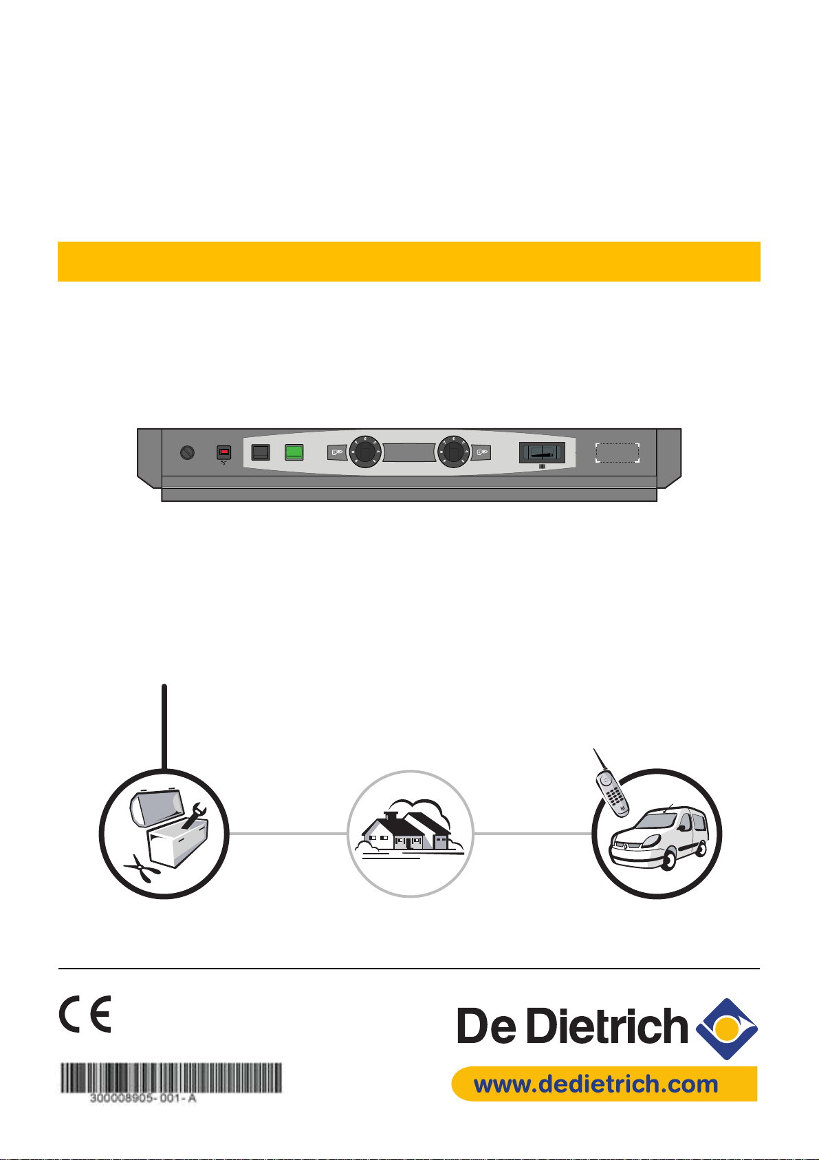
S3 standard control panel
Package MD4
English
23/01/06
TEST
STB
10A
l
0
30
M000483
Installation
instructions
Technical
instructions
Page 2

Contents
Symbols used. . . . . . . . . . . . . . . . . . . . . . . . . . . . . . . . . . . . . . . . . . . . . . . . . . . . . . . . . . . . . . . . . . . . . . . . . . . . . . . .3
Important recommendations . . . . . . . . . . . . . . . . . . . . . . . . . . . . . . . . . . . . . . . . . . . . . . . . . . . . . . . . . . . . . . . . . . .3
Description . . . . . . . . . . . . . . . . . . . . . . . . . . . . . . . . . . . . . . . . . . . . . . . . . . . . . . . . . . . . . . . . . . . . . . . . . . . . . . . . . .4
Presentation . . . . . . . . . . . . . . . . . . . . . . . . . . . . . . . . . . . . . . . . . . . . . . . . . . . . . . . . . . . . . . . . . . . . . . . . . . . . . . . . .5
Commissionning . . . . . . . . . . . . . . . . . . . . . . . . . . . . . . . . . . . . . . . . . . . . . . . . . . . . . . . . . . . . . . . . . . . . . . . . . . . . .6
Mounting - Connections . . . . . . . . . . . . . . . . . . . . . . . . . . . . . . . . . . . . . . . . . . . . . . . . . . . . . . . . . . . . . . . . . . . . . . .7
1 Control panel assembly . . . . . . . . . . . . . . . . . . . . . . . . . . . . . . . . . . . . . . . . . . . . . . . . . . . . . . . . . . . . . . . . . . . . . . . . . . . . . . . . . . . . .7
2 Electrical connections. . . . . . . . . . . . . . . . . . . . . . . . . . . . . . . . . . . . . . . . . . . . . . . . . . . . . . . . . . . . . . . . . . . . . . . . . . . . . . . . . . . . . . .7
3 Access to the connection terminal . . . . . . . . . . . . . . . . . . . . . . . . . . . . . . . . . . . . . . . . . . . . . . . . . . . . . . . . . . . . . . . . . . . . . . . . . . . . .7
4 Electricity supply - Flow controller . . . . . . . . . . . . . . . . . . . . . . . . . . . . . . . . . . . . . . . . . . . . . . . . . . . . . . . . . . . . . . . . . . . . . . . . . . . . .8
5 Connecting the burner . . . . . . . . . . . . . . . . . . . . . . . . . . . . . . . . . . . . . . . . . . . . . . . . . . . . . . . . . . . . . . . . . . . . . . . . . . . . . . . . . . . . . .9
6 Connecting the safety thermostat alarm report . . . . . . . . . . . . . . . . . . . . . . . . . . . . . . . . . . . . . . . . . . . . . . . . . . . . . . . . . . . . . . . . . .11
7 Connecting the flue gas thermometer (Package BP28). . . . . . . . . . . . . . . . . . . . . . . . . . . . . . . . . . . . . . . . . . . . . . . . . . . . . . . . . . . .12
Skeleton Diagrams. . . . . . . . . . . . . . . . . . . . . . . . . . . . . . . . . . . . . . . . . . . . . . . . . . . . . . . . . . . . . . . . . . . . . . . . . . .13
Spare parts . . . . . . . . . . . . . . . . . . . . . . . . . . . . . . . . . . . . . . . . . . . . . . . . . . . . . . . . . . . . . . . . . . . . . . . . . . . . . . . . .14
2
Control panel S3 23/01/06 - 300008905-001-A
Page 3
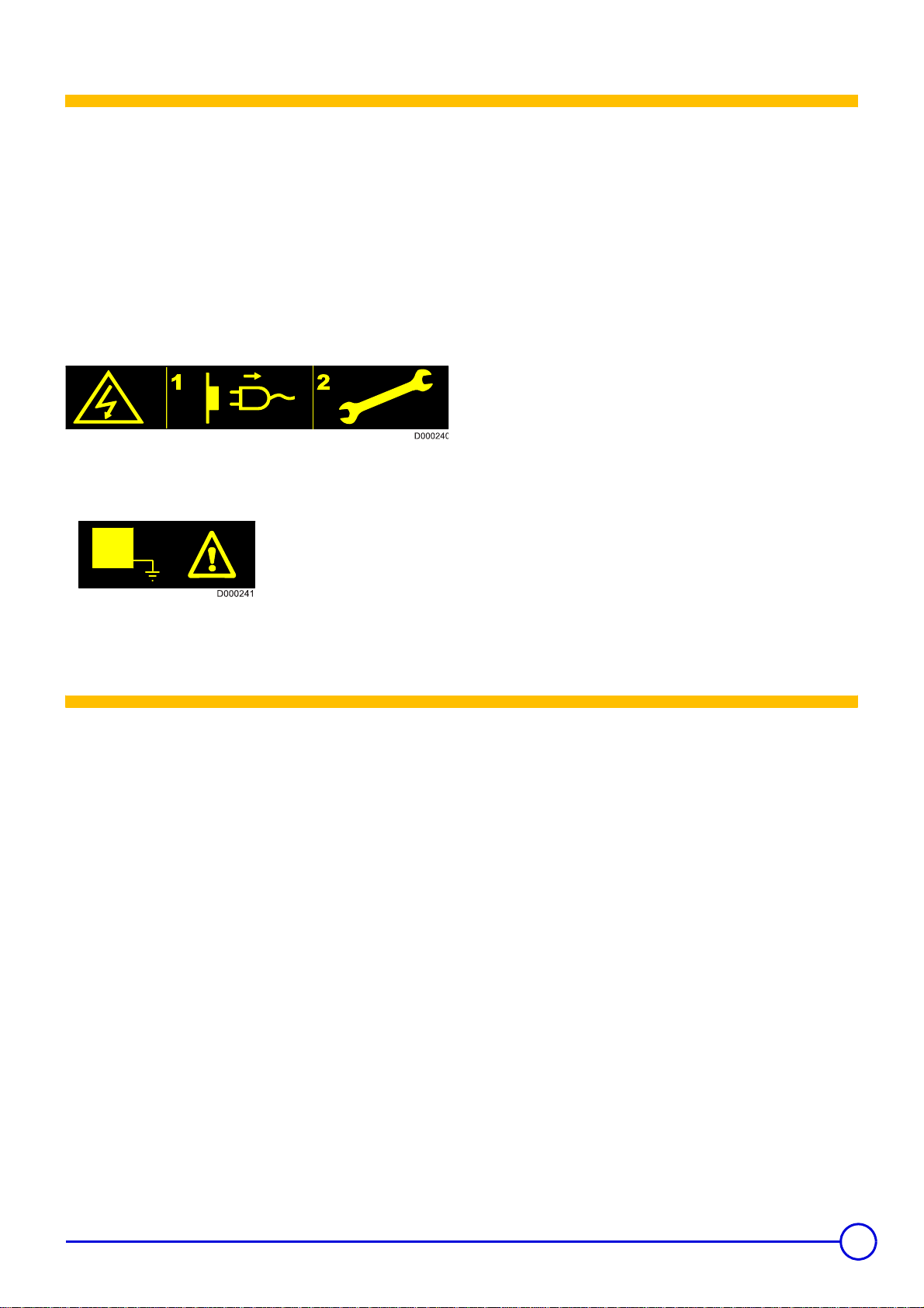
Caution danger
Risk of injury and damage to equipment. Attention must be
paid to the warnings on safety of persons and equipment
Specific information
Information must be kept in mind to maintain comfort
Reference
Z
Refer to another manual or other pages in this instruction
manual
DHW: Domestic hot water
Switch off the power supply before doing the work!.
Symbols used
This appliance must be connected to the earth.
Important recommendations
For a proper operating of the boiler, follow carefully the
instructions.
Any intervention on the appliance and heating equipment
must be carried out by a qualified technician.
The manufacturer is not liable for any improper use of the
appliance or failure to maintain or install the unit correctly
(the user shall take care to ensure that the system is
installed by a qualified fitter).
Keep to the polarity shown on the terminals : phase (L),
neutral (N) and earth
4
.
23/01/06 - 300008905-001-A Control panel S3
3
Page 4

1Introduction
Description
Standard electromechanical control panel for heating installations
without a control unit or for those which include a boiler room control
cabinet.
The control panel is used to control boilers with 1 or 2-stage burners.
The control panel S3 equips the boilers GT 330.
2 Presentation
Control panel S3 includes:
- 2 Boiler thermostats
- 1 Safety thermostat
The boiler thermostat regulates the boiler operating temperature.
The safety thermostat with manual reset ensures that the boiler
operates safely.
3 Operating principle
The boiler may be regulated:
- either by the boiler thermostats
If the boiler is fitted with a 2-stage burner, each thermostat is
assigned to the operation of one stage. The 2nd stage
thermostat must be set to a value at least 5°C lower than the 1st
stage thermostat.
- or by a control unit located in a cabinet
Operating security is provided by the safety thermostat with
manual reset.
optional:
Flue gas thermometer (Package BP28)
In the event that there is an abnormal rise in the
temperature in the boiler 110° C. Advise your installation
engineer.
4 Technical characteristics
Compliance / Stamp
This product complies to the requirements to the European Directives
and following standards:
- 73/23/EEC Low Voltage Directive
Reference Standard : EN 60.335.1
- 89/336/EEC Electromagnetic Compatibility Directive
Generic standards : EN1000-6-3 ; EN 61000-6-1
1
4
Control panel S3 23/01/06 - 300008905-001-A
Page 5

Presentation
76 1234
TEST
STB
10A
1. General ON (1) / OFF (0) switch
2. Switch Test-STB
Temporary action to test the safety thermostat
3. Boiler thermostats (30 to 85 °C)
A factory-set stop limits the maximum temperature to 75 °C. The
stop may be moved if necessary (See Moving the thermostat
stop).
4. Boiler thermometer
5. Location for flue gas thermometer (optional)
6. Timed circuit breaker (10 A) with delayed action and manual
reset
l
0
5
30
M000484
7. Safety thermostat with manual reset
(set to 110°C)
23/01/06 - 300008905-001-A Control panel S3
5
Page 6

Commissionning
The first start-up is to be performed by your installation
engineer.
Before starting the boiler, check if the installation is filled with water.
Start the boiler in the following order :
• Boiler temperature regulation by means of the thermostats
`Set the boiler thermostats 3 to the desired position. The 2nd
stage thermostat must be set to a value at least 5°C lower than
the 1st stage thermostat.
If there is no control unit, we advise you never to set the
boiler thermostat below mark 4 (approx. 40°C) in order to
avoid the risk of combustion products condensing on the
walls of the boiler.
`If necessary, change the position of the maximim temperature.
• Moving the thermostat stop
• Set the On/Off switch to 1.
5
6
7
8
9
M000154
A factory-set stop limits the maximum temperature to 75 °C.
To move the stop, proceed as follows:
`Pull the thermostat button out carefully (use pliers and a cloth).
`Remove the stop with the pliers.
`Put the stop in the hole of the desired higher temperature
(maximum 85°C).
• Control unit in boiler room electrical cabinet
See the instructions supplied with the control unit and any
remote control unit used.
• Check that safety thermostat 7 is properly set. To do so,
Unscrew the safety thermostat cover and press the reset button
using a screwdriver.
6
Control panel S3 23/01/06 - 300008905-001-A
Page 7

1 Control panel assembly
Refer to the technical and assembly instructions delivered with
Z
the boiler.
2 Electrical connections
Mounting - Connections
Only qualified professionnals may carry out electrical
connections, always with the power off.
As the electrical wiring has been carefuly checked in the
factory, the internal connections on the control panel must
not be changed in any way.
3 Access to the connection terminal
All connections are made with the terminal boxes designed for
that purpose on the back of the boiler's command board.
1
21
1
V
AS
10
3
9 8
T8
T
7
7 6 5
T
6T
2
T
1
4
L
1 N
L
N
2
3
L
I
A
0
V
5
0
H
z
Electrical connections must match the electrical diagrams delivered
with the equipment and comply with the instructions in the manual.
The equipment must have a power supply equipped with a omnipolar
switch with an opening distance above 3 mm.
The earth must comply with the NFC 15.100 (France) or the RGPT
(Belgium) standards.
8555N056
Bring the connecting cables to the control panel through the openings
located on the rear panel of the boiler and 1 or 2 cable channels,
depending upon the type of boiler.
Attach the cables to the cable clamps provided for this purpose.
Keep to the polarity shown on the terminals : phase (L), neutral (N)
and earth
23/01/06 - 300008905-001-A Control panel S3
4
.
7
Page 8

4 Electricity supply - Flow controller
89101112
34
567
21
LN
89101112
5 467
8219N087
ALI
T6T7T8S3VA
3 x 0,75 mm
230 V / 50 HzNL1T1T2
2
Make the electrical connection to the terminals 1, 2, 3.
Connection to the mains is done using a 3-wire cable with a cross
section of 0.75 mm² on the terminal block (terminals 1, 2, 3).
For other electrical connections, use the 3 wire cable with a diameter
of 0.75 mm².
The flow controller contact is connected to the safety circuit in series
(between terminal 5 on the terminal block and terminal L1 on the
burner, for example).
8
Control panel S3 23/01/06 - 300008905-001-A
Page 9

5 Connecting the burner
B4 S3 T2 T1 N
V/J
L1 B5 T6 T7 T8
8
4
5
6 7 1
3
2
8555N203
• Burner cable
8555N249
2 31
7-pin plug for 1-stage burners or stage 1 of 2-stage burners
4-pin plug for stage 2 of the burner
Connector block with connection pins to the control panel
terminal block
The control panel is supplied with the burner power cable.
One end of this cable is fitted with two European 7 and 4 pin sockets
and the other with a terminal with male connecting pins.
• Control panel
•Burner side
Burner fitted with pin connectors
Refer to the burner cable diagram.
Burner without plug-in connectors
In this case, the connectors supplied with the burner cable must be
rewired.
The diagram shows the wire numbers and the terminals of the burner
connectors.
12 11 10
V
A S
3T
9
8
T7
8 7 6
T6 T
2
T1
5 4
L
1 N
L
N
2
3
L
I
A
0V
5
0H
z
8555N058
Connect the terminal block to terminals 4 to 12 on the fixed terminal
block on the control panel using the male pins.
23/01/06 - 300008905-001-A Control panel S3
9
Page 10

The table below specifies the way in which the cables are to be
connected on the burner control box.
Connector
terminal -No
L1 7 Continuous phase from the safety thermostat Burner main supply
4
N6Neutral taken after On/Off Neutral terminal
T1/T2 5/4 Dry contact of the stage 1 boiler thermostat Insert in the control circuit of boiler stage 1
S3 8 Burner alarm indicator Alarm output (phase)
T6 1 Stage 2 boiler thermostat input Insert in the control circuit of burner stage 2
T7 3 Stage 2 “boiler off” thermostat output Connect only if the burner is of the modulating type
T8 2 Stage 2 “boiler on” thermostat output Insert in the contro l circuit of burner stage 2
Wire No From Connection to the burner control box
V/J Earth connection Earth connection
If the electrical characteristics of the burner exceed the following
values
- inrush current > 16 A or
- P > 450 W or
-I > 2 A cos
ϕ = 0.7
The burner controls must be relayed, e.g. with the relaying kit
(package BP 51, optional)
.
1
M000150
7-pin plugs for connecting to the control panel and burner
connectors.
10
Control panel S3 23/01/06 - 300008905-001-A
Page 11

6 Connecting the safety thermostat alarm report
12
11
VA
10 9 8 7 6 5 4
S
3 T
8
T7 T
6
T
2
T1
L
1
L
N
N
2
3
L
I
A
0
V
5
0
H
z
The insulated pin on the safety thermostat is used to connect an
alarm report (thermostat with reversal contact).
If the safety thermostat trips, a 230 V signal is present on this
terminal.
`Open the control panel (3 screws at the back) to access the
back of the safety thermostat.
8555N057
23/01/06 - 300008905-001-A Control panel S3
11
Page 12

7 Connecting the flue gas thermometer (Package BP28)
M000493
An optional flue gas thermometer may be fitted on the front of the
control panel.
To do so:
- Cut the cover off with a cutter along the edges of the coloured
rectangle
- Clip the thermometer into the opening
- Bring the sensor to the back of the boiler via the cable channel and
insert it in the flue gas pipe.
12
Control panel S3 23/01/06 - 300008905-001-A
Page 13

Skeleton Diagrams
SCHEMA DE PRINCIPE - STROMLAUFPLAN - WIRING DIAGRAM - PRINCIPESCHEMA GT 330 STANDARD
N° : 300007760-001-A
TEST STB SCHAKELAARTEST STB SWITCHZTB
BRANDER SCHAKELAARBURNER SWITCHZB
ALARM LAMPJEALARM INDICATORVA
VEILIG HEIDS THERMOSTAATCONDENSER THERMOSTATTS2
VEILIGHEIDSTHERMOSTAATHIGH LIMIT THERMOSTATTS1
KETELTHERMOSTAAT 2de TRAPBOILER THERMOSTAT 2nd STAGETCH2
KETELTHERMOSTAAT 1st TRAPBOILER THERMOSTAT 1st STAGETCH1
NULLEIDERNEUTRALN
FASEPHASEL
THERMISCHE BEVEILIGINGCIRCUIT BREAKERDJ10A
AARDINGEARTHÇ
12
BA
1a
1b
VA
AANSLUITINGSKLEMMENCONNECTING BOARDBA
11
BA
10
θ
θθ
θ
2
1
4
TCH2
1
1a
ZTB
θ
θθ
θ
24
1
TCH1
1
2
θ
θθ
θ
11a
DJ10A
11a
ZB
TS1
BA
9
BA
8
1
2
θ
θθ
θ
TS2
S3
BA
7
BA
6
BA
5
BA
T1L1 T2 T6 T7 T8
Ê
ÊÊ
Ê
N
4
BA
TEST STB SCHALTERINTERRUPTEUR TEST STBZTB
BRENNER SCHALTERINTERRUPTEUR BRULEURZB
ALARMLEUCHTEVOYANT ALARMEVA
BRENNWERTTAUSCHER STWTHERMOSTAT DE SECURITE CONDENSEURTS2
SICHERHEITSTEMPERATURBEGRENZERTHERMOSTAT DE SECURITETS1
KESSEL TEMPERATURREGLER 2.STUFETHERMOSTAT DE CHAUDIERE 2eme ALLURETCH2
KESSEL TEMPERATURREGLER 1.STUFETHERMOSTAT DE CHAUDIERE 1ere ALLURETCH1
NULLEITERNEUTREN
PHASEPHASEL
LEISTUNGSSCHALTERDISJONCTEURDJ10A
SCHUTZLEITERTERREÇ
ANSCHLUSSLEISTEBARRETTEBA
22a
ZB
3
BA
L
2
BA
N
23/01/06 - 300008905-001-A Control panel S3
13
Page 14

Spare parts
23/01/06 - 300008905-002-A
To order a spare part, quote the reference number next to the part required.
Control panel S3 for GT 330
1
4
9
3
10
18
17
12
10A
5
4
6
3
7
8
11
9
5
4
6
3
7
8
9
8
6
10
11
2
14
15
7
13
1
2
11
V
A S3
1
0
T
9
8 T7
87 6
T6 T2
T
1
L
5
5
1
4
16
DE DIETRICH THERMIQUE S.A.S. - Spare parts centre
4 rue d’Oberbronn - F-67110 REICHSHOFFEN -
cpr
dedietrichthermique.com
+33 (0)3 88 80 26 50 - + +33 (0)3 88 80 26 98
*
M000487
Page 15

Rep Code no. Description
1 100004299 Standard complete control panel
2 8219-0508 Painted control panel base
3 8557-0505 Cover
4 300007160 Side plate
5 200005221 Plastic coated panel
6 9532-5027 Green S/S bipolar switch
7 9536-5161 Thermometer
8 9532-5092 Bipolar switch
9 9536-3314 110 °C safety thermostat
10 9536-3364 30 to 90 °C setting thermostat
11 8555-5501 Setting button + Pin
12 9534-0286 Timed circuit breaker (10 A)
13 200005244 Standard beam
14 8219-4905 Electric circuit
15 9531-7395 7-pin plug
16 9531-7384 4-pin plug
17 9536-5613 Contact spring for pocket
18 9758-1286 Spring for pocket
23/01/06 - 300008905-001-A Control panel S3
15
Page 16

FR
DE DIETRICH THERMIQUE S.A.S.
www.dedietrich.com
Direction des Ventes France
57, rue de la Gare
F- 67580 MERTZWILLER
+33 (0)3 88 80 27 00
+33 (0)3 88 80 27 99
AT
DE DIETRICH HEIZTECHNIK
www.dedietrich.com
Am Concorde Park 1 - B 4 / 28
A-2320 SCHWECHAT / WIEN
+43 (0)1 / 706 40 60-0
+43 (0)1 / 706 40 60-99
office@dedietrich.at
DE
BE
CH
DE DIETRICH HEIZTECHNIK
www.dedietrich.com
Rheiner Strasse 151
D- 48282 EMSDETTEN
+49 (0)25 72 / 23-5
+49 (0)25 72 / 23-102
info@dedietrich.de
VAN MARCKE
www.vanmarcke.be
Weggevoerdenlaan 5
B- 8500 KORTRIJK
+32 (0)56/23 75 11
VESCAL S.A.
www.chauffer.ch / www.heizen.ch
Z.I de la Veyre, St-Légier
1800 VEVEY 1
+41 (0)21 943 02 22
+41 (0)21 943 02 33
LU
RU
CN
NEUBERG S.A.
www.dedietrich.com
39 rue Jacques Stas
L- 2010 LUXEMBOURG
+352 (0)2 401 401
DE DIETRICH
www.dedietrich.com
8 Gilyarovskogo Str. 7
R- 129090 MOSCOW
+7 495.974.16.03
+7 495.974.66.08
dedietrich@nnt.ru
DE DIETRICH
www.dedietrich.com
Room 512, Tower A, Kelun Building
12A Guanghua Rd, Chaoyang District
C-100020 BEIJING
+86 (0)106.581.4017
+86 (0)106.581.4018
+86 (0)106.581.7056
+86 (0)106.581.4019
contact
BJ
@dedietrich.com.cn
In the interest of customers, De Dietrich Thermique SAS are continuous ly endea vouring to make imp rovements in product quality. All the specificatio ns stated in this document are therefore subject to change without notice
AD001Z • 02.2006
DE DIETRICH THERMIQUE
57, rue de la Gare F- 67580 MERTZWILLER - BP 30
www.dedietrich.com
 Loading...