

Page 1
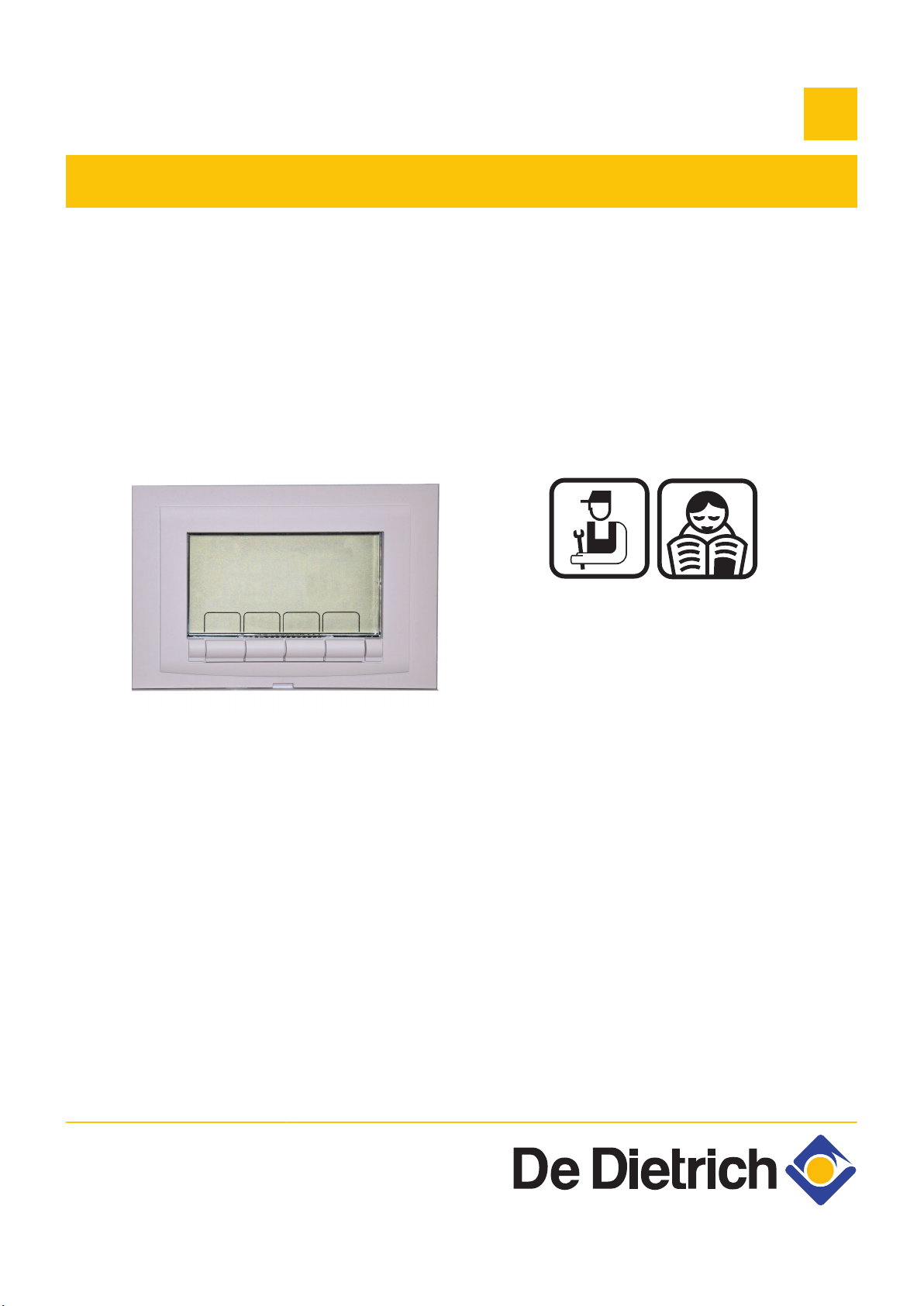
Regulation
C003108-A
IniControl
For C 330 / C 630 ECO
Ireland
EN
Installation, User
and Service
Manual
7600717-001-06
Page 2

Contents
1 Introduction ................................................................................................4
1.1 Symbols used .......................................................4
1.2 Liabilities ...............................................................4
1.2.1 Manufacturer’s liability .............................................4
1.2.2 Installer’s liability .....................................................5
1.2.3 User’s liability ..........................................................5
1.3 Certifications .........................................................6
2 Safety instructions and recommendations ..............................................7
2.1 Recommendations ................................................7
3 Technical specifications ............................................................................8
3.1 Sensor characteristics .........................................8
4 Installation ..................................................................................................9
4.1 Package list ...........................................................9
4.1.1 Standard delivery ....................................................9
4.1.2 Accessories .............................................................9
4.2 Installing the outside sensor ...............................9
4.2.1 Choice of the location ..............................................9
4.2.2 Connecting the outside sensor ..............................10
4.3 Fitting and connecting the control panel .........10
4.4 Electrical connections ........................................11
4.4.1 Connecting a direct heating circuit ........................11
4.4.2 Connection in cascade (with OpenTherm AD287)
option ....................................................................11
5 Commissioning ........................................................................................13
5.1 Control panel .......................................................13
5.1.1 Description of the keys ..........................................13
5.1.2 Description of the display ......................................14
5.2 Switch on the instrument panel ........................15
5.3 Reading out measured values ...........................16
5.3.1 Reading out measured values ..............................16
5.3.2 Readout from the hour counter and percentage of
successful starts ....................................................17
5.3.3 Status and sub-status ...........................................18
1
260216 - 7600717-001-06
Page 3

Contents
5.4 Changing the settings ........................................19
5.4.1 General .................................................................19
5.4.2 Parameter descriptions .........................................19
5.4.3 Modification of the user-level parameters .............23
5.4.4 Modification of the installer-level parameters ........24
5.4.5 Setting the maximum heat input for central heating
operation ...............................................................25
5.4.6 Return to the factory settings Reset Param ..........26
5.4.7 Carrying out an auto-detect ...................................26
5.4.8 Setting the manual mode ......................................27
6 Troubleshooting .......................................................................................28
6.1 Shutdowns and lock-outs ..................................28
6.1.1 General .................................................................28
6.2 Error memory ......................................................35
6.2.1 Error readout memorised ......................................35
6.2.2 Deletion of the error display ..................................36
2
260216 - 7600717-001-06
Page 4

3
260216 - 7600717-001-06
Page 5
IniControl For C 330 / C 630 ECO
1 Introduction
1.1 Symbols used
1. Introduction
In these instructions, various danger levels are employed
to draw the user’s attention to particular information. In so
doing, we wish to safeguard the user’s safety, highlight
hazards and guarantee correct operation of the appliance.
DANGER
Risk of a dangerous situation causing serious
physical injury.
WARNING
1.2 Liabilities
Risk of a dangerous situation causing slight
physical injury.
CAUTION
Risk of material damage.
Signals important information.
¼Signals a referral to other instructions or other pages
in the instructions.
1.2.1. Manufacturer’s liability
Our products are manufactured in compliance with the
requirements of the various applicable European
260216 - 7600717-001-06
Directives. They are therefore delivered with [ marking
and all relevant documentation.
4
Page 6

1. Introduction
IniControl For C 330 / C 630 ECO
In the interest of customers, we are continuously
endeavouring to make improvements in product quality.
All the specifications stated in this document are therefore
subject to change without notice.
Our liability as the manufacturer may not be invoked in the
following cases:
4 Failure to abide by the instructions on using the
appliance.
4 Faulty or insufficient maintenance of the appliance.
4 Failure to abide by the instructions on installing the
appliance.
1.2.2. Installer’s liability
The installer is responsible for the installation and
commissioning of the appliance. The installer must
respect the following instructions:
4 Read and follow the instructions given in the manuals
provided with the appliance.
4 Carry out installation in compliance with the prevailing
legislation and standards.
4 Perform the initial start up and carry out any checks
necessary.
4 Explain the installation to the user.
4 If a maintenance is necessary, warn the user of the
obligation to check the appliance and maintain it in
good working order.
4 Give all the instruction manuals to the user.
1.2.3. User’s liability
To guarantee optimum operation of the appliance, the
user must respect the following instructions:
4 Read and follow the instructions given in the manuals
provided with the appliance.
4 Call on qualified professionals to carry out installation
and initial start up.
4 Get your installer to explain your installation to you.
4 Ensure the Appliance is serviced in accordance with
the manufacturer’s instructions by a suitable qualified
person.
4 Keep the instruction manuals in good condition close
to the appliance.
5
260216 - 7600717-001-06
Page 7

IniControl For C 330 / C 630 ECO 1. Introduction
This appliance is not intended to be used by persons
(including children) whose physcial, sensory or mental
capacity is impaired or persons with no experience or
knowledge, unless they have the benefit, through the
intermediary of a person responsible for their safety, of
supervision or prior instructions regarding use of the
appliance. Care should be taken to ensure that children
do not play with the appliance.
If the mains power lead is damaged it must be replaced
by the original manufacturer, the manufacturer’s dealer or
another competent person to prevent hazardous
situations.
1.3 Certifications
This product complies to the requirements to the
european directives and following standards:
4 2006/95/EC Low Voltage Directive. Reference
Standard: EN60.335.1.
4 2004/108/EC Electromagnetic Compatibility Directive.
Generic standards: EN1000-6-3 , EN 61000-6-1.
260216 - 7600717-001-06
6
Page 8
2. Safety instructions and recommendations IniControl For C 330 / C 630 ECO
2 Safety instructions and
recommendations
2.1 Recommendations
WARNING
Any intervention on the appliance and heating equipment
must be carried out by a qualified engineer.
For a proper operating of the boiler, follow carefully the
instructions.
Keep this document close to the place where the boiler is
installed.
7
260216 - 7600717-001-06
Page 9
IniControl For C 330 / C 630 ECO 3. Technical specifications
3 Technical specifications
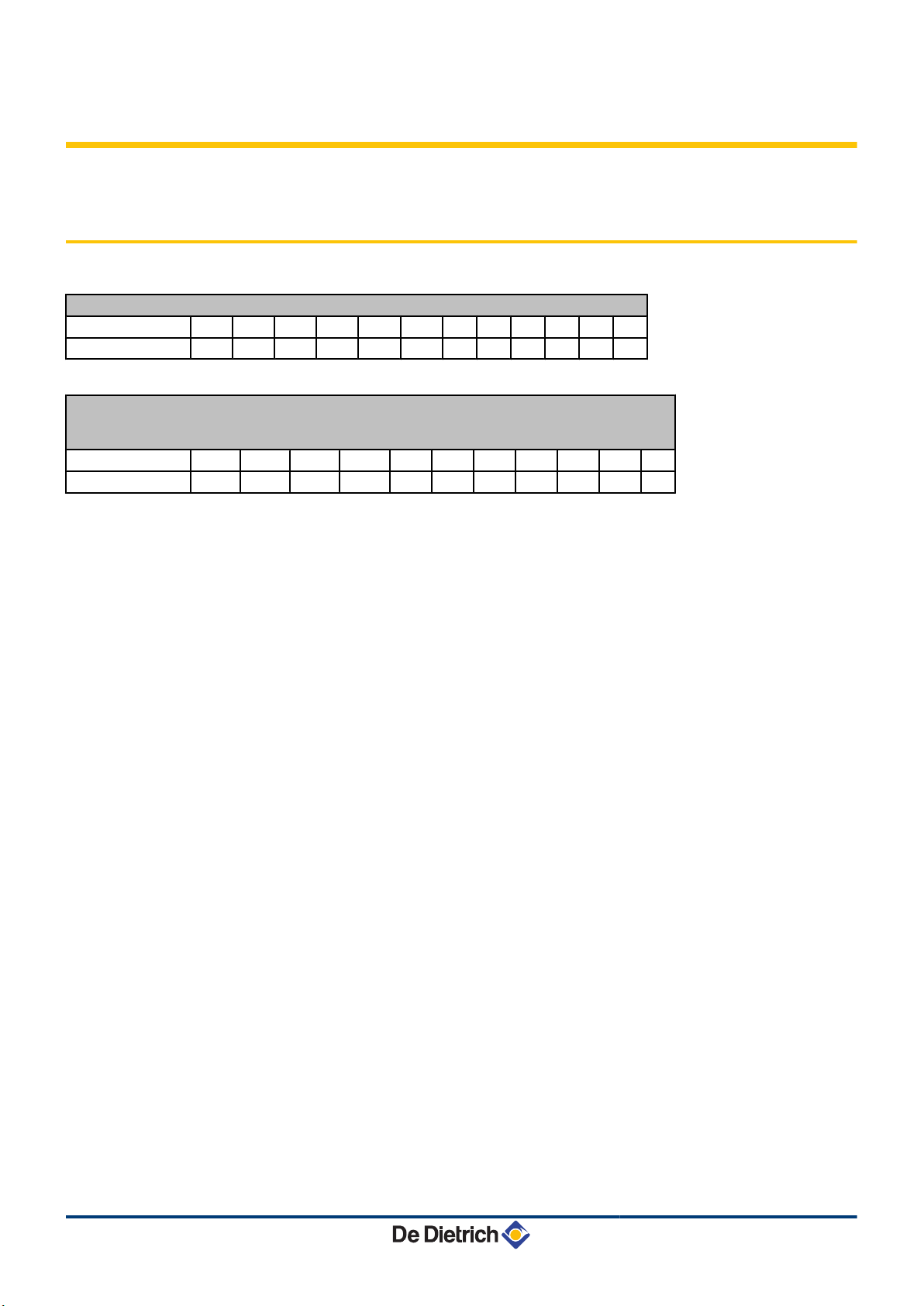
3.1 Sensor characteristics
Outside sensor
Temperature in °C -20 -16 -12 -8 -4 0 4 8 12 16 20 24
Resistance in Ω 2392 2088 1811 1562 1342 1149 984 842 720 616 528 454
Specifications of the flow sensor circuit B + C
Specifications of the DHW sensor
Specifications of the system sensor
Temperature in °C 0 10 20 25 30 40 50 60 70 80 90
Resistance in Ω 32014 19691 12474 10000 8080 5372 3661 2535 1794 1290 941
260216 - 7600717-001-06
8
Page 10
4. Installation
4 Installation
4.1 Package list
IniControl For C 330 / C 630 ECO
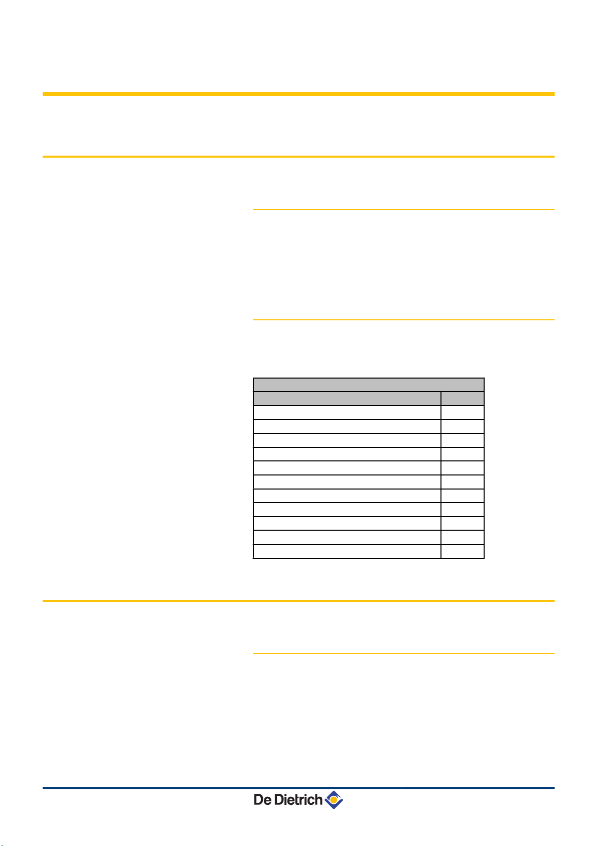
4.1.1. Standard delivery
The delivery includes:
4 The control panel with the IniControl module
4 Installation, use and maintenance manual for the control panel
4.1.2. Accessories
Various options are available depending on the configuration of the
installation:
Control system options
Description package
BUS connection cable (length 12 m) AD134
voice remote monitoring module AD152
OpenTherm interface AD287
Outside sensor FM46
RX11 cable AD124
Modulating room thermostat AD265
Radio-controlled modulating room thermostat AD266
Digital room thermostat AD137
Wireless settable ambient thermostat AD200
SCU-S05 PCB
SCU-S03 PCB
4.2 Installing the outside sensor
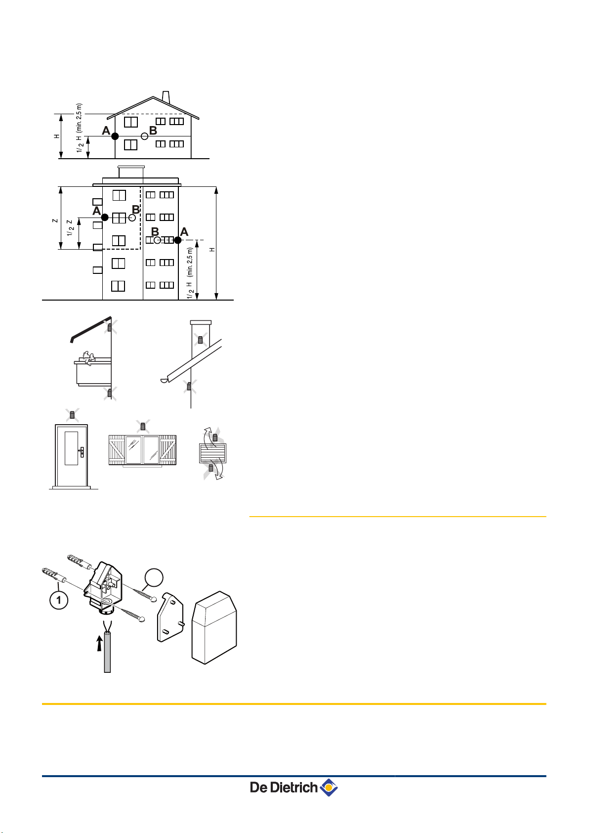
4.2.1. Choice of the location
It is important to select a place that allows the sensor to measure the
outside conditions correctly and effectively.
Advised positions:
4 on one face of the area to be heated, on the north if possible
4 half way up the wall in the room to be heated
4 under the influence of meteorological variations
9
260216 - 7600717-001-06
Page 11
8800N001-C
8800N002-C
8800N003-C
2
IniControl For C 330 / C 630 ECO
4. Installation
4 protected from direct sunlight
4 easy to access
A
B
H
Z
Recommended position
Possible position
Inhabited height controlled by the sensor
Inhabited area controlled by the sensor
Positions to be avoided:
4 masked by a building element (balcony, roof, etc.)
4 close to a disruptive heat source (sun, chimney, ventilation grid,
etc.)
4.2.2. Connecting the outside sensor
Mount the sensor using the screws and dowels provided.
A
Z
Inserts
Ø4 wood screw
¼For the connection of the outside temperature sensor, refer to
the chapter "Electrical Connections".
4.3 Fitting and connecting the control panel
260216 - 7600717-001-06
¼Refer to the boiler’s installation and service manual.
10
Page 12
M002709-C
1
3
2
On/off
OT
BL
RL
PCU
SCU-S05
PUMP
ECS S EXT S DE
2 1 21
M002710-C
5
6
7
8
9
0
1
2
3
4
6
7
8
5
1
2
4
4
3
On/off
OT
BL
RL
PCU
PUMP
OTH / MB
INTERFACE
OTH
9
10
11
12 13
4. Installation IniControl For C 330 / C 630 ECO
4.4 Electrical connections
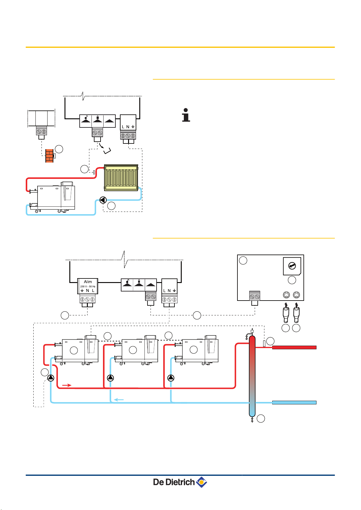
4.4.1. Connecting a direct heating circuit
A
Connect the outside temperature sensor.
SCU-S05 PCB = Option
Z
E
Heating connection pump.
Connect a safety thermostat if the heating circuit is for
underfloor heating.
4 Remove the bridge.
4 Connect the wires from the safety thermostat to the
connector.
4.4.2. Connection in cascade (with OpenTherm
AD287) option
11
A
Z
E
R
Master boiler (DIEMATIC iSystem)
Secondary boiler (DIEMATIC iSystem or IniControl)
Secondary boiler (DIEMATIC iSystem or IniControl)
Cable BUS
260216 - 7600717-001-06
Page 13

IniControl For C 330 / C 630 ECO 4. Installation
T
Y
U
I
O
P
a
z
e
Boiler pump
Low loss header
Cascade outlet sensor
Connect the sensor to the terminal block S SYST on the
master boiler.
Boiler power supply - 230 V
Connection cable linking the Opentherm from the PCU to
the Opentherm on the interface
OpenTherm (AD287) interface board to be fitted in the
boiler control panel
Encoding wheel used to set the addresses of the slave
boilers. Set to 1 on boiler 2 - Set to 2 on boiler 3 - etc.
BUS cable to the master boiler
BUS cable to the slave boilers
260216 - 7600717-001-06
12
Page 14
-
)
L
m
rrr
ddd
T
y
1
2
SERVICE
°C°Fh
barPsi
% rpm
kW uA
x10 l/min
°CSt:
M002715-A
t
h
j
A B
E F
C D
5. Commissioning IniControl For C 330 / C 630 ECO
5 Commissioning
5.1 Control panel
For operation of the boiler C 630 ECO: Each module has
its own instrument panel.
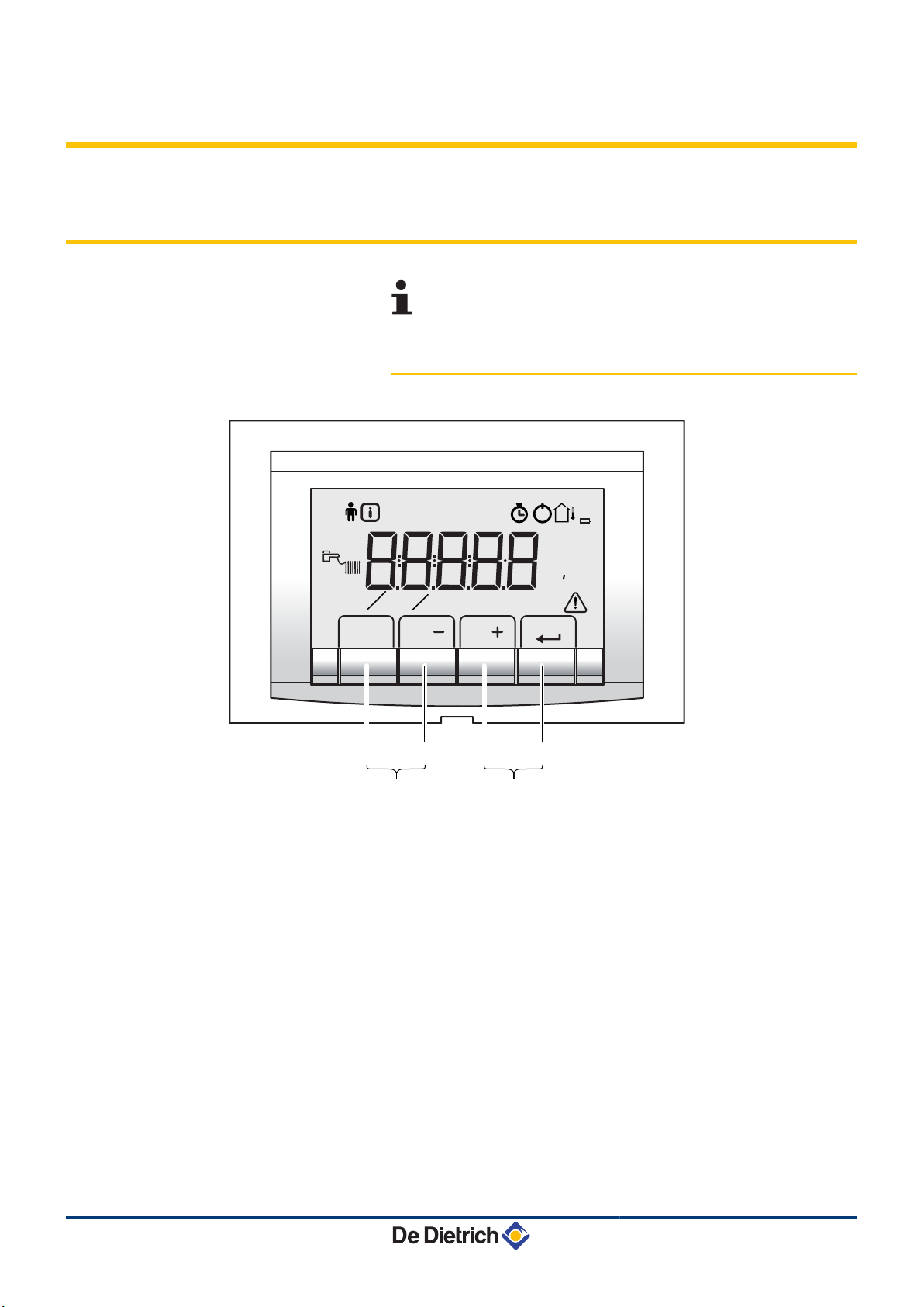
5.1.1. Description of the keys
13
A
B
C
D
E
F
Return button j, Escape G or Manual reset t
Heating temperature button d or [-]
DHW temperature button r or [+]
S [Enter] Key
) [Chimney-sweeping] keys
Press keys A and B simultaneously
f [Menu] keys
Press keys C and D simultaneously
260216 - 7600717-001-06
Page 15

-
)
L
m
r
r
r
d
d
d
T
y
1
2
SERVICE
°C°Fh
barPsi
% rpm
kW uA
x10 l/min
°CSt:
M002716-A
t
h
j
-
)
L
m
rrr
d
d
d
T
y
1
2
SERVICE
°C°Fh
barPsi
% rpm
kW uA
x10 l/min
°CSt:
M002717-A
t
h
j
-
)
L
m
m
r
r
ddd
T
y
g
1
2
SERVICE
°C°Fh
barPsi
% rpm
kW uA
x10 l/min
°CSt:
M002735-A
t
h
j
-
)
L
m
rrr
ddd
T
y
1
2
SERVICE
°C°Fh
barPsi
% rpm
kW uA
x10 l/min
°CSt:
M002719-A
t
h
j
IniControl For C 330 / C 630 ECO 5. Commissioning
5.1.2. Description of the display
Key functions
n
G
t
d
[-]
r
[+]
®
Operating modes
n
d
D
r
S
Back to the previous level without saving the
modifications made
Manual reset
Central heating function:
Access to the max. heating temperature parameter.
To reduce a value
DHW function:
Access to sanitary hot water temperature parameter.
To increase a value
Access the selected menu or confirm a value modification
State heating pump
Heating programme deactivated:
The heating function is deactivated
State DHW pump
DHW off
260216 - 7600717-001-06
m
m
g
Flame output level
n
e
r
t
y
Manual mode
The DHW function is in economic mode (deactivated)
Boiler protection is active
Low output level 0 - 25 %
Average output level 25 - 50 %
High output level 50 - 75 %
Output level 75 - 100 %
14
Page 16
-
)
L
m
rrr
ddd
T
y
1
2
SERVICE
°C°Fh
barPsi
% rpm
kW uA
x10 l/min
°CSt:
M002720-A
t
h
j
-
)
L
m
rrr
ddd
T
y
1
2
SERVICE
°C°Fh
barPsi
% rpm
kW uA
x10 l/min
°CSt:
M002721-A
t
h
j
5. Commissioning
System pressure
n
IniControl For C 330 / C 630 ECO
bar
Other information
n
"
!
)
-
K
Pressure indicator:
The symbol is displayed next to the installation’s pressure
value. If no water pressure sensor is connected, -.appears on the display
User menu:
Parameters at user level can be changed
Information menu:
Reading the various current values
Chimney-sweeping position:
Forced full or part load for CO2 measurement
Service menu:
Parameters at installer level can be changed
Display with the symbols:
$ + K + Z (Maintenance message)
\
a
I
M
a
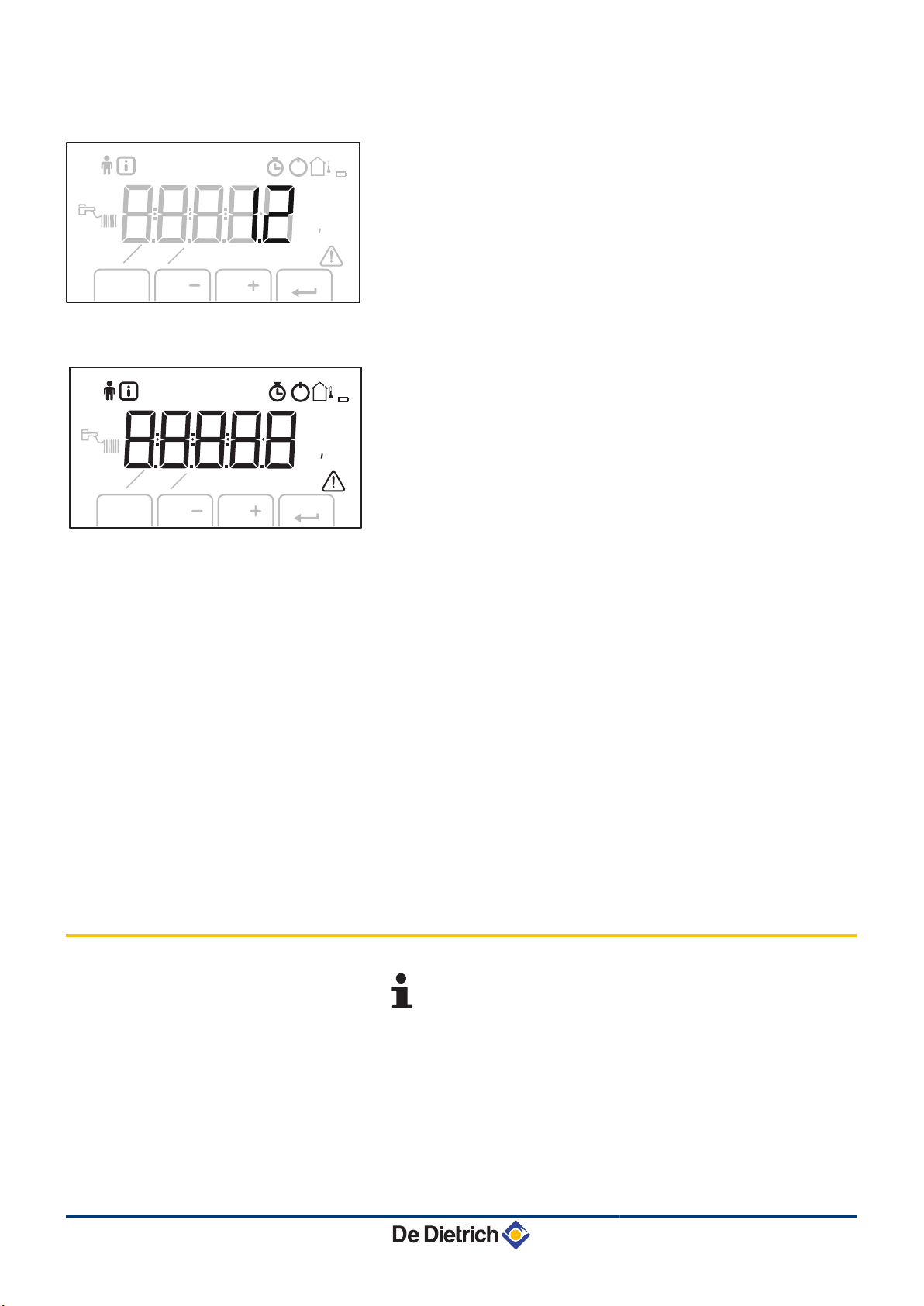
5.2 Switch on the instrument panel
The instrument panel IniControl is ready for use, as soon as the
power to the boiler is switched on.
Hour counter menu:
Readout of the operating hours, number of successful
starts and hours on mains supply
Blocking:
After 5 resets in under 1 hour, the appliance should be
switched off and switched on again before resetting
Outside temperature sensor present
The symbol is displayed when the boiler pump is
operating
Defect:
Boiler indicates a fault. This is indicated by an E code
and a flashing display
For operation of the boiler C630 Eco: The features and
instructions described are for each boiler module.
15
1. Open the gas valve on the boiler.
2. Turn on the boiler using the on/off switch.
3. Set the controls (thermostats, control system) so that they request
heat.
260216 - 7600717-001-06
Page 17
IniControl For C 330 / C 630 ECO
5. Commissioning
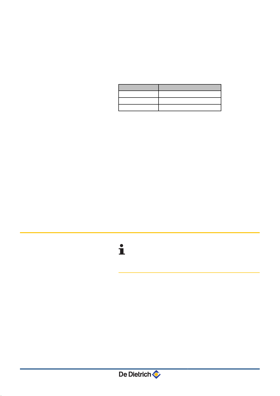
4. The start-up cycle begins and cannot be interrupted. During the
start-up cycle, the display shows the following information:
A short test where all segments of the display are visible.
fK[xx
pK[xx
: Software version
: Parameter version
The version numbers are displayed alternately.
By pressing the S key for a short time, the current operating status
is shown on the display:
Heat demand Heat demand stopped
1: Fan ON 5: Burner stop
": Boiler is igniting 6: Post-circulation of the pump
3: Heating System 0: Standby
In STAND-BY, the display normally shows the water pressure next to
0 (only when the hydraulic pressure sensor is connected) and the
symbols d and H.
Error during the start-up procedure:
4 No information is shown on the display:
- Check the mains supply voltage
- Check the main fuses
- Check the fuses on the control panel:
(F1 = 2 AT, F2 = 8 AT)
- Check the connection of the mains lead to the connector in the
instrument box
4 A fault is indicated on the display by the fault symbol a and a
flashing fault code.
- The meaning of the error codes is given in the error table.
- Press for 3 seconds on key J to restart the boiler.
5.3 Reading out measured values
5.3.1. Reading out measured values
The following current values can be read off the information menu
Q:
4 5200 = Fan speed.
4 5201 = Fan speed Set point.
4 5203 = Burner flame signal.
4 5204 = Gas valve open (1) or closed (0).
4 5205 = GpS connected.
4 5206 = Ignition phase.
4 5207 = Ionization current.
4 5208 = Heat output requested.
4 5209 = Release input.
For operation of the boiler C630 Eco: The features and
instructions described are for each boiler module.
260216 - 7600717-001-06
16
Page 18
C003058-A
r
h
j
d
y
5x
2x
5. Commissioning
IniControl For C 330 / C 630 ECO
4 5210 = Pressure switch minimum VPS.
4 5213 = Burner start.
4 5214 = Trap protection activated.
4 5215 = internal.
4 5216 = internal.
4 5217 = internal.
4 5218 = internal.
4 5219 = internal.
4 5220 = internal.
4 5226 = Heat output (Gvc).
4 5241 = State.
4 5242 = Sub-status.
4 5244 = Flow temperature.
4 5245 = Exchanger temperature.
4 5246 = Return temperature.
4 5247 = Water pressure.
4 5251 = Outside temperature (Only if an outside temperature
sensor is connected).
4 5252 = Inlet 0-10 Volts.
4 5256 = Internal set point (°C).
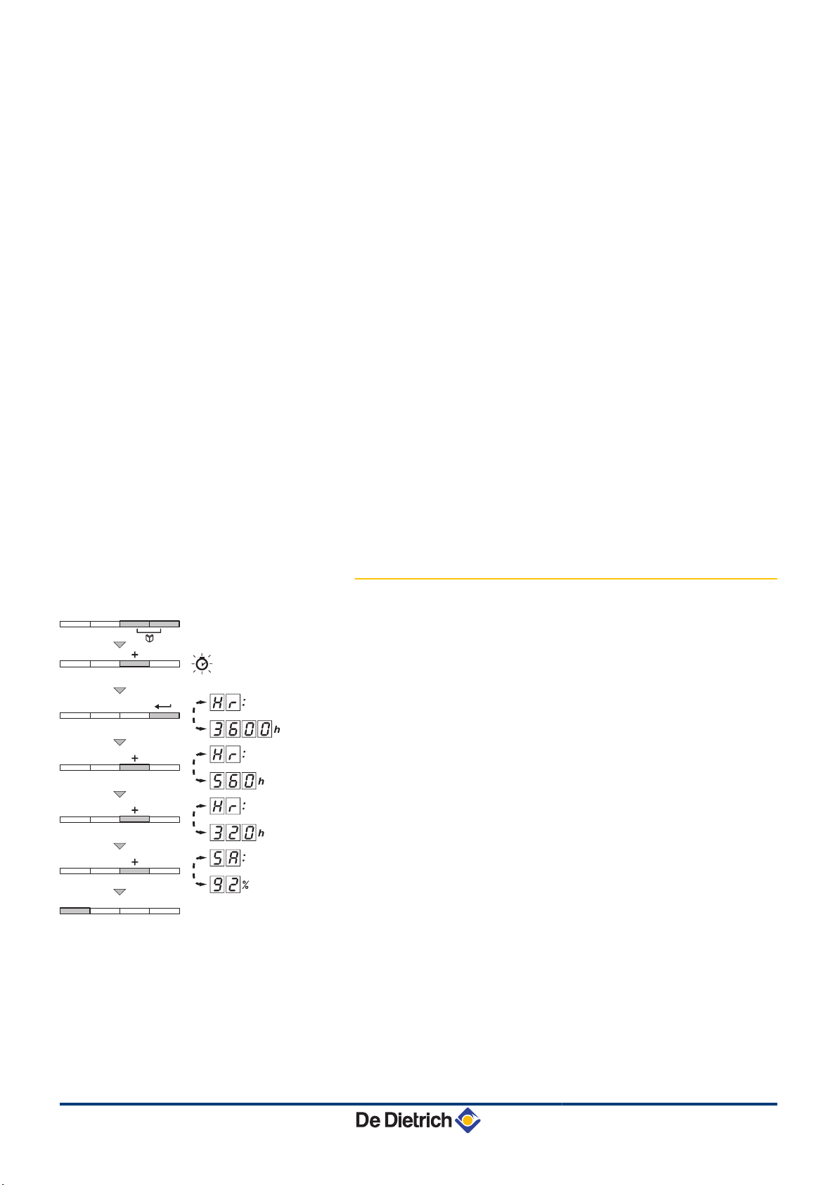
5.3.2. Readout from the hour counter and
percentage of successful starts
1. Press the two keys f simultaneously and then key [+] until the
symbol \ flashes on the menu bar.
2. Press the S key.
operation
3600
3. Press the [+] key. The display shows D.
alternating with the number of operating hours in central heating
operation
560
4. Press the [+] key. The display shows @.
alternating with the percentage of successful starts
example).
5. Press the j key 2 times to return to the current operating mode.
and the number of hours of boiler
hr
(for example) are displayed alternately.
is displayed,
hr
(for example).
is displayed,
5Z
92
% (for
17
260216 - 7600717-001-06
Page 19
IniControl For C 330 / C 630 ECO 5. Commissioning
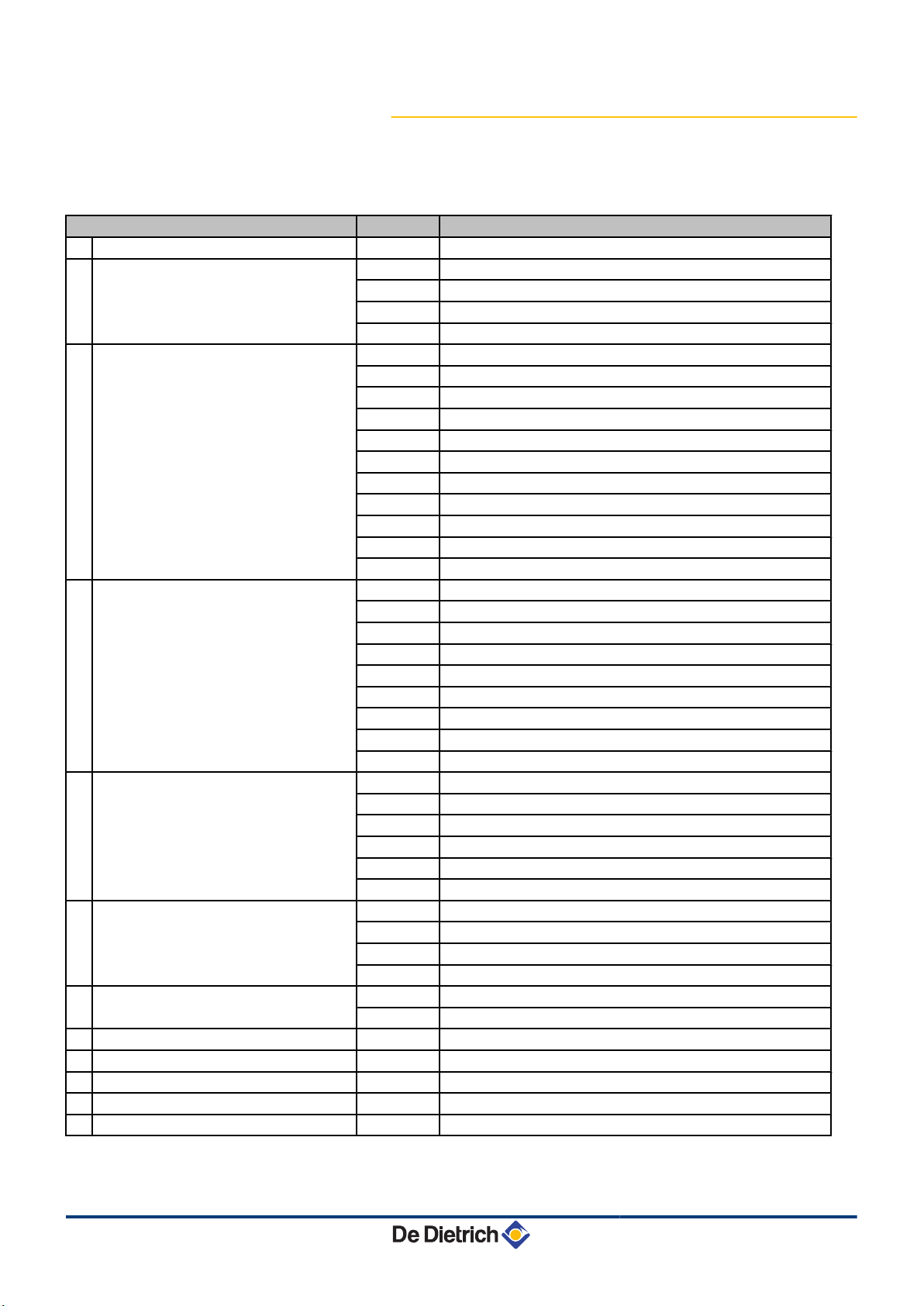
5.3.3. Status and sub-status
The information menu Q gives the following status and sub-status
numbers:
St status Sub-status Operation
0 Rest 0 Rest
1 Anti-short cycle activated
1 Boiler start (Heat demand)
2 Burner start
3 Boiler on heating service
5 Burner stop
6 Switching off the boiler
8 Control stop 0 Awaiting burner start-up
9 Blocking XX Shutdown code XX
10 Lock out
11 Chimney-sweeping position: Low speed
12 Chimney-sweeping position: CH speed
13 Chimney-sweeping position: DHW speed
2 Open isolating valve
3 Start-up of the boiler pump
4 Wait for the correct temperatures for burner start
10 Open gas valve (External)
11 Fan start-up
12 Opening of the flue gas flue damper
13 Preventilation
14 Awaiting closure of the RL contact (if the function is activated)
15 Burner on switch request
16 Leak proofing system test
17 Pre-ignition
18 Ignition
19 Check flame presence
20 Inter-ignition time delay
30 Nominal internal set point
31 Limited internal set point
32 Output control
33 Temperature protection gradient level 1 (Modulate down)
34 Temperature protection gradient level 2 (Part load)
35 Temperature protection gradient level 3 (Blockage)
36 Modulate up for flame control
37 Temperature stabilisation time
38 Cold start
40 Burner shutdown request
41 Post-ventilation
42 Fan speed reduction
43 Closure of the flue gas flue damper
44 Stop fan
45 Output restricted by flue gas temperature
60 Post-operation time delay on the boiler pump
61 Stop boiler pump
62 Close isolating valve
63 Start anti short cycle
1 Anti-short cycle activated
260216 - 7600717-001-06
18
Page 20
5. Commissioning IniControl For C 330 / C 630 ECO
5.4 Changing the settings
5.4.1. General
The boiler control panel is set for the most common heating
systems. With these settings, practically all heating systems operate
correctly. The user or installer can optimise the parameters according
to own preferences.
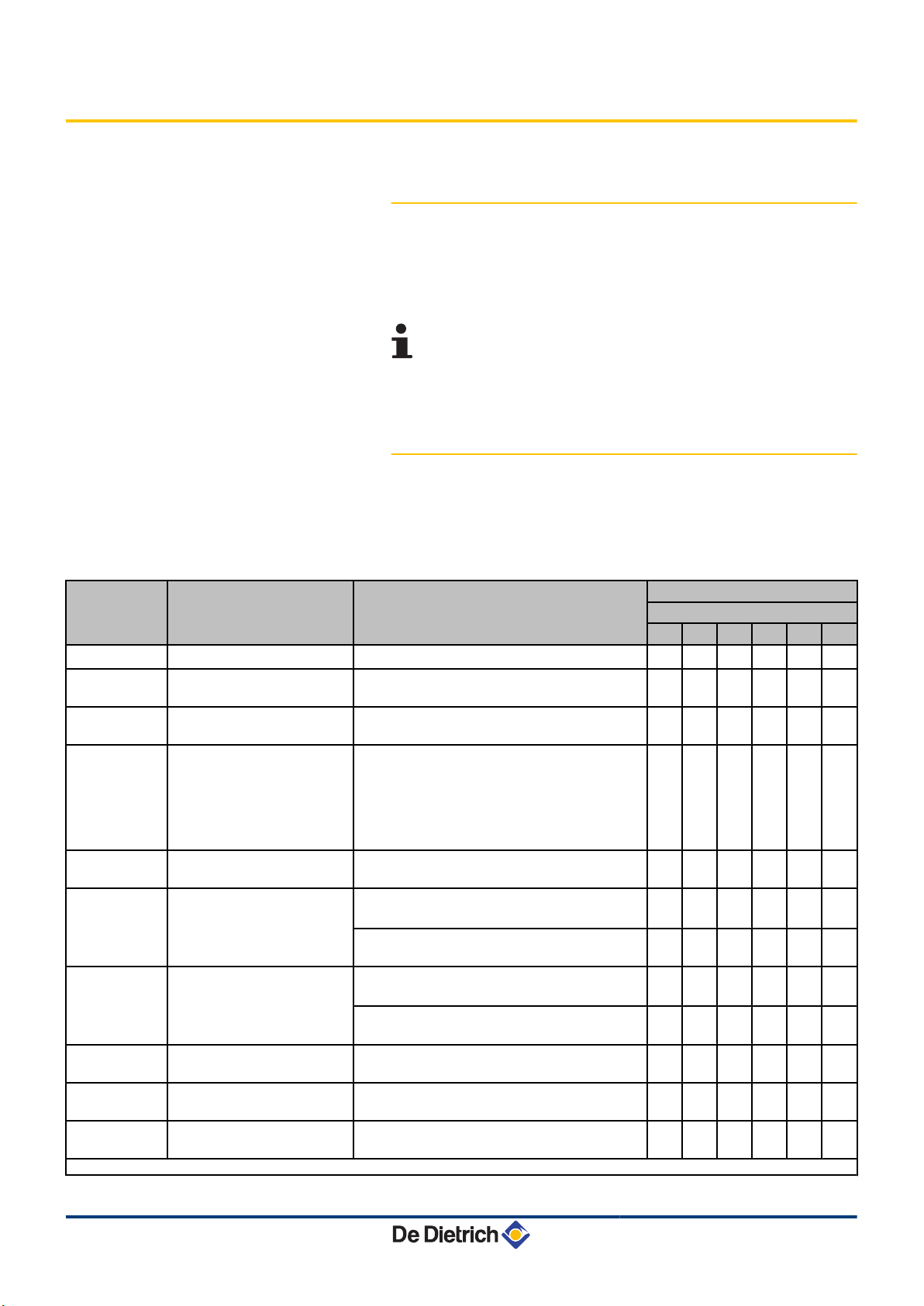
For the settings of the C630 Eco boiler: The parameters
and settings described are for each boiler module. Each
parameter changing must therefore be done identical on
each module.
5.4.2. Parameter descriptions
Boiler type C 330 ECO
n
Factory setting
Parameter
p1
p2
p3
p4
p5
p17
p18
p19
p20
p21
(1) Do not modify these factory settings unless absolutely necessary. E.g. to adapt the boiler to: G20 (Gas H)
Description Adjustment range
Flow temperature: T
Post-circulation of the pump
Boiler regulation
Display screen
Brightness of display lighting
Maximum fan speed
Minimum fan speed
offset Minimum fan speed
Start speed
Maximum flow temperature
of system
SET
20 to 90 °C
1 to 98 minutes
99 minutes = continuous
0 = Heating deactivated
1 = Heating activated
0 = Simple
1 = Comprehensive
2 = Automatic switching to simple after 3
minutes
3 = Automatic switching to simple after 3
minutes; Key blocking is active
0 = Dimmed
1 = Bright
G25 (Gas L)
(x100 rpm)
G20 (Gas H)
(x100 rpm)
G25 (Gas L)
(x100 rpm)
G20 (Gas H)
(x100 rpm)
Do not modify
(x1 rpm)
Do not modify
(x100 rpm)
0 to 90 °C 90 90 90 90 90 90
(1)
(1)
C 330 ECO
280 350 430 500 570 650
80 80 80 80 80 80
53 56 35 38 43 42
52 55 35 38 43 41
14 15 9 10 11 10
14 15 9 10 11 10
25 25 13 14 14 14
5 5 5 5 5 5
1 1 1 1 1 1
2 2 2 2 2 2
1 1 1 1 1 1
0 50 50 50 0 50
19
260216 - 7600717-001-06
Page 21
IniControl For C 330 / C 630 ECO 5. Commissioning
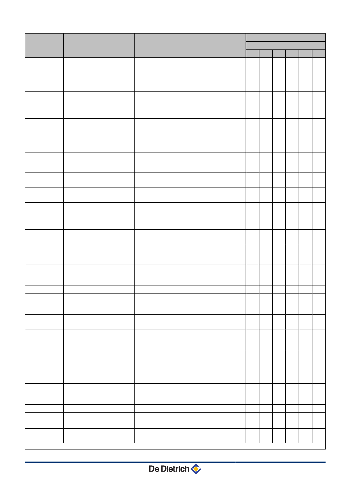
Factory setting
Parameter Description Adjustment range
C 330 ECO
280 350 430 500 570 650
Heat curve set point
(Maximum outside
p22
temperature)
0 to 30 °C 20 20 20 20 20 20
(Only with an outside
temperature sensor)
Heat curve set point
p23
(Flow temperature)
(Only with an outside
0 to 90 °C 20 20 20 20 20 20
temperature sensor)
Heat curve set point
(Minimum outside
p24
temperature)
-30 to 0 °C -15 -15 -15 -15 -15 -15
(Only with an outside
temperature sensor)
Antifreeze temperature
p25
(Only with an outside
from - 30 to 0°C - 10 - 10 - 10 - 10 - 10 - 10
temperature sensor)
p26
p27
Fault relay function X4
(If connected)
Fault relay function X5
(If connected)
0 = Operation signal
1 = Alarm signal
0 = Operation signal
1 = Alarm signal
0 0 0 0 0 0
1 1 1 1 1 1
Minimum water pressure
p28
Wps
(Only with the hydraulic
0 - 3 bar (MPa) (x 0,1bar (MPa))
0 = Not connected
0 0 0 0 0 0
pressure sensor connected)
p29
Minimum gas pressure
check Gps
0 = Not connected
1 = Connected
0 0 0 0 0 0
Hydraulic valve running time
p30
HdV
0 to 255 seconds 0 0 0 0 0 0
(If connected)
Flue gas damper running
p31
time FgV
0 to 255 seconds 0 0 0 0 0 0
(If connected)
p32
p33
p34
Release waiting time 0 to 255 seconds 0 0 0 0 0 0
Gas valve leak proving
system CCE
( If connected)
Live/neutral inversion
0 = Not connected
1 = Connected
0 = Off
1 = On
0 0 0 0 0 0
0 0 0 0 0 0
1 = Shutdown without frost-protection
p35
Shutdown input function
2 = Shutdown with frost protection
1 1 1 1 1 1
3 = Lock-out with frost protection (Pump only)
0 =0-10 V Wilo control PCB
p36
From Analogue output (0 10V)
SCU-S05 control PCB
1 = 0-10 V Grundfoss control PCB
2 = PWM pump
3 = Heat output feedback
0 0 0 0 0 0
4 = Temperature feedback
From Analogue input
p37
(0-10V)
SCU-S05 control PCB
p38
p39
p40
(1) Do not modify these factory settings unless absolutely necessary. E.g. to adapt the boiler to: G20 (Gas H)
Boiler inertia Do not modify 6 6 6 6 6 6
Display units
Maintenance message
0 =OpenTherm regulator
1 = Analogue temperature-based control (°C)
2 = Analogue heat output-based control (%)
0 = À/ bar
1 = F / PSI
0 = Service messages off
1 = Service messages on
0 0 0 0 0 0
0 0 0 0 0 0
0 0 0 0 0 0
260216 - 7600717-001-06
20
Page 22
5. Commissioning IniControl For C 330 / C 630 ECO
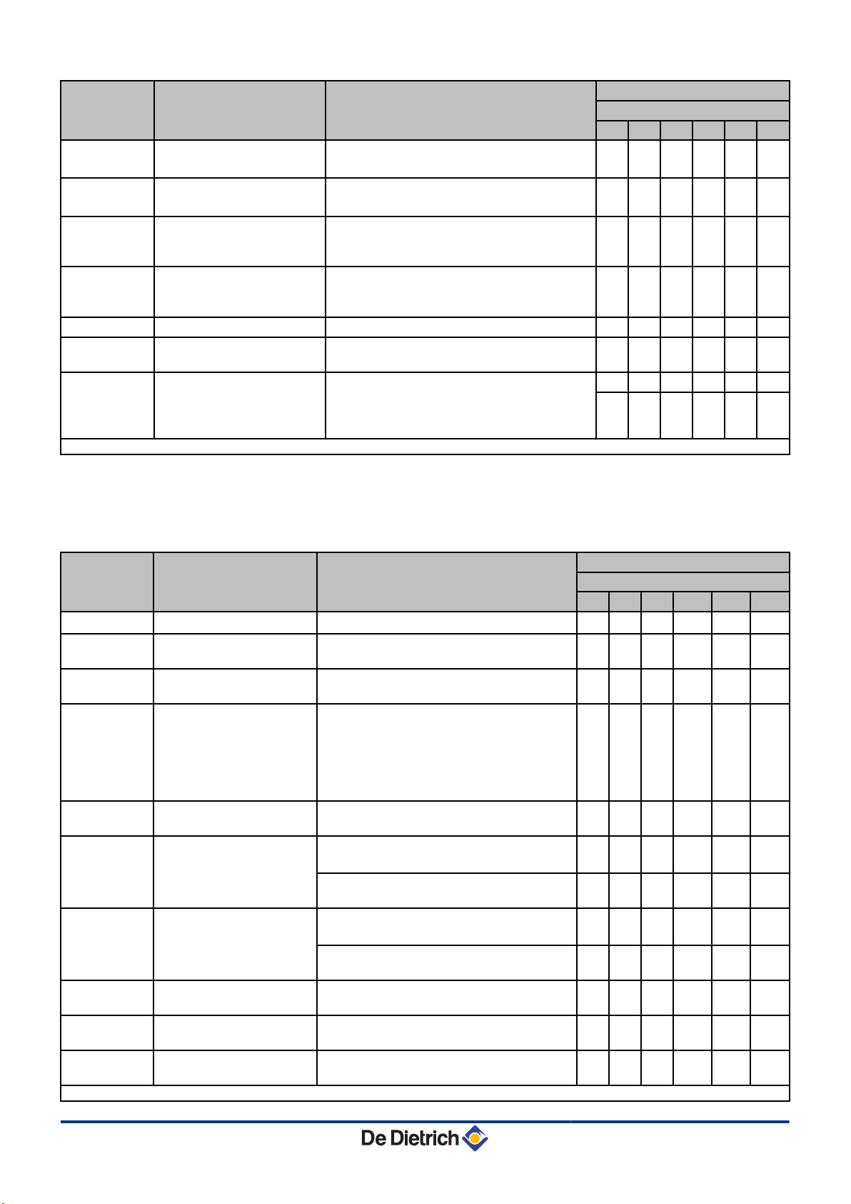
Factory setting
Parameter Description Adjustment range
C 330 ECO
280 350 430 500 570 650
p41
p42
Service operating hours
Service burning hours
( x 100)
Do not modify
( x 100)
Do not modify
175 175 175 175 175 175
30 30 30 30 30 30
Setting the pump speed
p43
(Minimum pump speed for
2 - 10 (x 10%) 2 2 2 2 2 2
central heating operation)
Setting the pump speed
p44
(Maximum pump speed for
6 - 10 (x 10%) 10 10 10 10 10 10
central heating operation)
p45
Zd
df and dV
ΔTModulate down 10 to 30 °C 25 25 25 25 25 25
Detection of connected
SCUs
Factory setting
0 = No detection
1 = Detection
To restore the factory settings or when
replacing the main PCB, enter the values dF
and dU from the type plate in parameters
0 0 0 0 0 0
X X X X X X
Y Y Y Y Y Y
df and dV
(1) Do not modify these factory settings unless absolutely necessary. E.g. to adapt the boiler to: G20 (Gas H)
Boiler type C 630 ECO
n
Factory setting
Parameter
Description Adjustment range
C 630 ECO
560 700 860 1000 1140 1300
p1
p2
p3
Flow temperature: T
Post-circulation of the
pump
Boiler regulation
SET
20 to 90 °C
1 to 98 minutes
99 minutes = continuous
0 = Heating deactivated
1 = Heating activated
80 80 80 80 80 80
5 5 5 5 5 5
1 1 1 1 1 1
0 = Simple
1 = Comprehensive
p4
Display screen
2 = Automatic switching to simple after 3
minutes
2 2 2 2 2 2
3 = Automatic switching to simple after 3
minutes; Key blocking is active
p5
p17
p18
p19
p20
p21
(1) Do not modify these factory settings unless absolutely necessary. E.g. to adapt the boiler to: G20 (Gas H)
Brightness of display
lighting
Maximum fan speed
Minimum fan speed
offset Minimum fan speed
Start speed
Maximum flow temperature
of system
0 = Dimmed
1 = Bright
G25 (Gas L)
(x100 rpm)
G20 (Gas H)
(x100 rpm)
G25 (Gas L)
(x100 rpm)
G20 (Gas H)
(x100 rpm)
Do not modify
(x1 rpm)
Do not modify
(x100 rpm)
(1)
(1)
1 1 1 1 1 1
53 56 35 38 43 42
52 55 35 38 43 41
19 18 13 12 14 13
19 18 13 12 14 13
0 50 0 50 0 50
25 25 14 14 15 16
0 to 90 °C 90 90 90 90 90 90
21
260216 - 7600717-001-06
Page 23
IniControl For C 330 / C 630 ECO 5. Commissioning
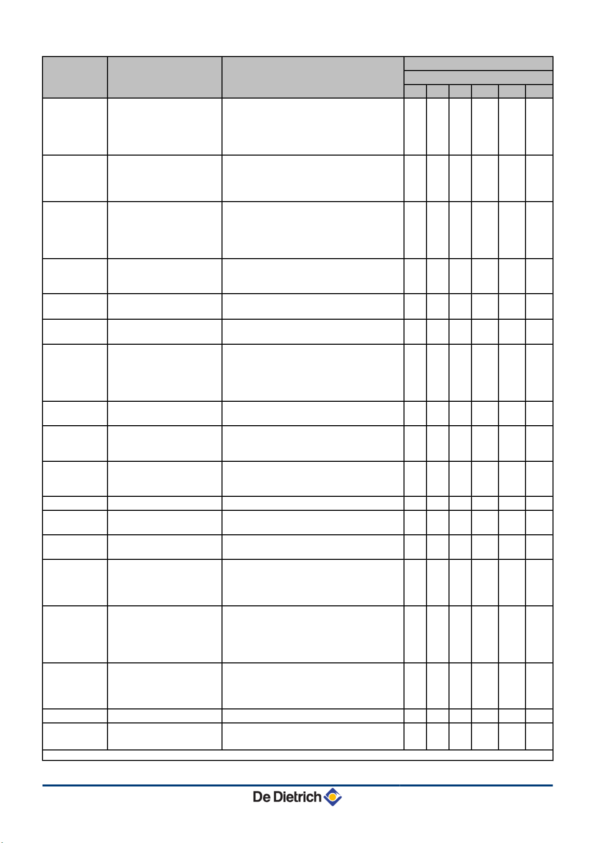
Factory setting
Parameter Description Adjustment range
C 630 ECO
560 700 860 1000 1140 1300
Heat curve set point
(Maximum outside
p22
temperature)
0 to 30 °C 20 20 20 20 20 20
(Only with an outside
temperature sensor)
Heat curve set point
p23
(Flow temperature)
(Only with an outside
0 to 90 °C 20 20 20 20 20 20
temperature sensor)
Heat curve set point
(Minimum outside
p24
temperature)
-30 to 0 °C -15 -15 -15 -15 -15 -15
(Only with an outside
temperature sensor)
Antifreeze temperature
p25
(Only with an outside
from - 30 to 0°C - 10 - 10 - 10 - 10 - 10 - 10
temperature sensor)
p26
p27
Fault relay function X4
(If connected)
Fault relay function X5
(If connected)
0 = Operation signal
1 = Alarm signal
0 = Operation signal
1 = Alarm signal
0 0 0 0 0 0
1 1 1 1 1 1
Minimum water pressure
p28
Wps
(Only with the hydraulic
pressure sensor
0 - 3 bar (MPa) (x 0,1bar (MPa))
0 = Not connected
0 0 0 0 0 0
connected)
p29
Minimum gas pressure
check Gps
0 = Not connected
1 = Connected
0 0 0 0 0 0
Hydraulic valve running
p30
time HdV
0 to 255 seconds 0 0 0 0 0 0
(If connected)
Flue gas damper running
p31
time FgV
0 to 255 seconds 0 0 0 0 0 0
(If connected)
p32
p33
p34
Release waiting time 0 to 255 seconds 0 0 0 0 0 0
Gas valve leak proving
system CCE
Live/neutral inversion
0 = Not connected
1 = Connected
0 = Off
1 = On
0 0 0 0 0 0
0 0 0 0 0 0
1 = Shutdown without frost-protection
p35
Shutdown input function
2 = Shutdown with frost protection
3 = Lock-out with frost protection (Pump
1 1 1 1 1 1
only)
0 =0-10 V Wilo control PCB
p36
From Analogue output (0 10V)
SCU-S05 control PCB
1 = 0-10 V Grundfoss control PCB
2 = PWM pump
3 = Heat output feedback
0 0 0 0 0 0
4 = Temperature feedback
From Analogue input
p37
(0-10V)
SCU-S05 control PCB
p38
p39
(1) Do not modify these factory settings unless absolutely necessary. E.g. to adapt the boiler to: G20 (Gas H)
Boiler inertia Do not modify 6 6 6 6 6 6
Display units
0 =OpenTherm regulator
1 = Analogue temperature-based control
(°C)
2 = Analogue heat output-based control (%)
0 = À/ bar
1 = F / PSI
0 0 0 0 0 0
0 0 0 0 0 0
260216 - 7600717-001-06
22
Page 24
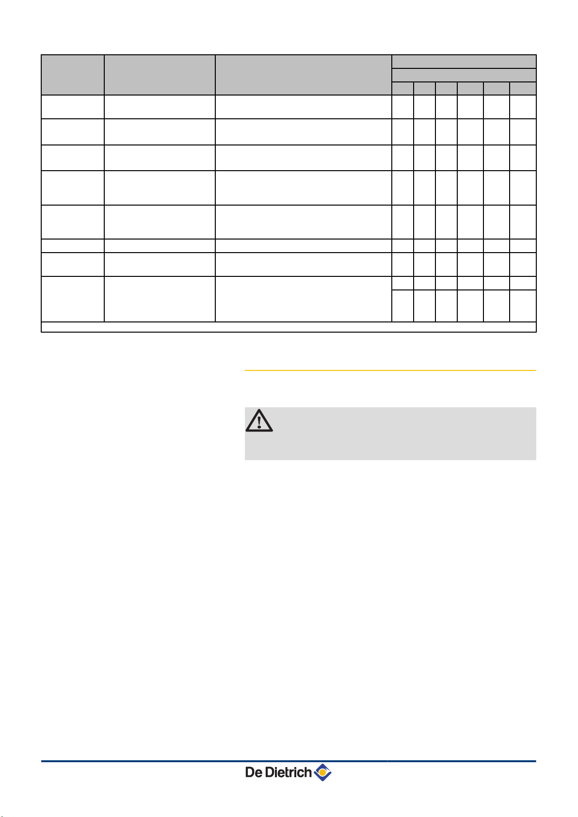
5. Commissioning IniControl For C 330 / C 630 ECO
Factory setting
Parameter Description Adjustment range
p40
p41
p42
p43
p44
p45
Zd
df and dV
(1) Do not modify these factory settings unless absolutely necessary. E.g. to adapt the boiler to: G20 (Gas H)
Maintenance message
Service operating hours
Service burning hours
Setting the pump speed
(Minimum pump speed for
central heating operation)
Setting the pump speed
(Maximum pump speed for
central heating operation)
ΔTModulate down 10 to 30 °C 25 25 25 25 25 25
Detection of connected
SCUs
Factory setting
0 = Service messages off
1 = Service messages on
( x 100)
Do not modify
( x 100)
Do not modify
2 - 10 (x 10%) 2 2 2 2 2 2
6 - 10 (x 10%) 10 10 10 10 10 10
0 = No detection
1 = Detection
To restore the factory settings or when
replacing the main PCB, enter the values
dF and dU from the type plate in parameters
df and dV
C 630 ECO
560 700 860 1000 1140 1300
0 0 0 0 0 0
175 175 175 175 175 175
30 30 30 30 30 30
0 0 0 0 0 0
X X X X X X
Y Y Y Y Y
Y
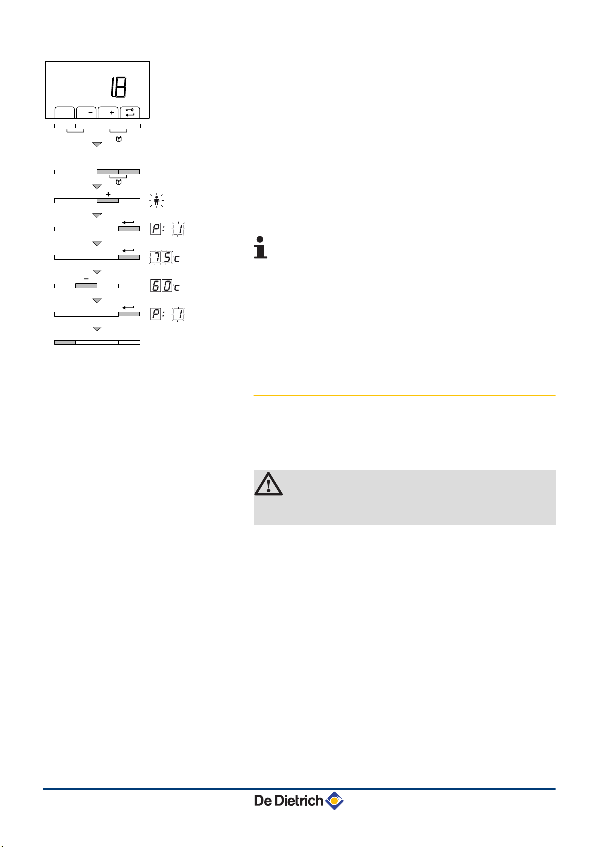
5.4.3. Modification of the user-level parameters
Parameters p001 to p007 can be changed by the user.
CAUTION
Modification of the factory settings may be detrimental to
the functioning of the appliance.
23
260216 - 7600717-001-06
Page 25
)
r
d
bar
C003050-A
t
h
j
h
j
1x
2x
IniControl For C 330 / C 630 ECO 5. Commissioning
1. Press the two keys f simultaneously and then key [+] until the
symbol W flashes on the menu bar.
2. Select the users menu using the key S.
p[001
is displayed
with 1 flashing.
3. Press the S key a second time. The value
°C appears and
80
flashes (for example).
4. Change the value by pressing the [-] or [+] key. In this example
using key [-] to
5. Confirm the value with the S key.
flashing.
1
60
°C.
p[001
is displayed with
6. Press the j key 2 times to return to the current operating mode.
The parameters
same way as
p001
p002
to
p007
are changed in the
. After step 2, use the [+] key to
move to the required parameter.
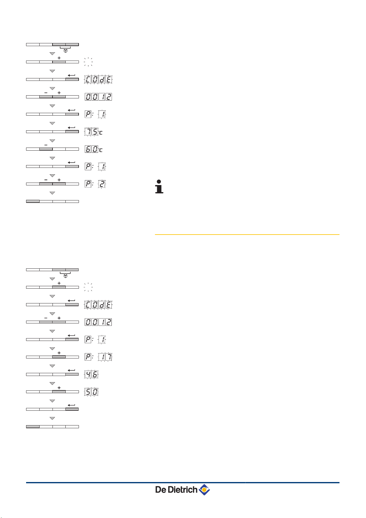
5.4.4. Modification of the installer-level
parameters
Parameters p017 to c0nf must only be modified by a
qualified professional. To prevent unwanted settings, some
parameter settings can only be changed after the special access code
0012 is entered.
CAUTION
Modification of the factory settings may be detrimental to
the functioning of the appliance.
260216 - 7600717-001-06
24
Page 26
C003059-A
h
j
-
3x
2x
C003060-A
3x
...x
...x
2x
-
h
j
5. Commissioning
IniControl For C 330 / C 630 ECO
1. Press the two keys f simultaneously and then key [+] until the
symbol - flashes on the menu bar.
2.
Select the fitter menu using the ® key.
c0de
appears on the
display.
3. Use keys [-] or [+] to input the installer code
4. Confirm using key S.
p[001
is displayed with 1 flashing.
5. Press the S key a second time. The value
0012
75
.
°C appears and
flashes (for example).
6. Change the value by pressing the [-] or [+] key. In this example
using key [-] to
7. Confirm the value with the S key:
flashing.
1
60
°C.
p[001
is displayed with
8. If necessary, set other parameters by selecting them using the
[-] or [+] keys.
9. Press the j key 2 times to return to the current operating mode.
The boiler also returns to operating status if no keys are
pressed for 3 minutes.
5.4.5. Setting the maximum heat input for central
heating operation
The speed can be changed using parameter p17. To do this,
proceed as follows:
1. Press the two keys f simultaneously and then key [+] until the
symbol - flashes on the menu bar.
2. Select the installers menu using the key S.
c0de
on the display.
3. Use keys [-] or [+] to input the installer code
4. Confirm using key S.
5. Press the [+] key to go to parameter
is displayed with 1 flashing.
p[1
p[17
0012
.
6. Confirm using key S.
7. Press the [+] key to increase the speed from
(see the graphs for the associated heat output).
50
8. Confirm the value with the S key.
46
9. Press the j key 2 times to return to the current operating mode.
appears
.
to, for example,
25
260216 - 7600717-001-06
Page 27
C003062-A
3x
...x
-
IniControl For C 330 / C 630 ECO
5. Commissioning
5.4.6. Return to the factory settings Reset Param
1. Press the two keys f simultaneously and then key [+] until the
symbol - flashes on the menu bar.
2. Select the installers menu using the key S.
c0de
on the display.
3. Use keys [-] or [+] to input the installer code
4. Confirm using key S.
5. Press the [+] key several times.
Cn1
6. Press the S key.
flashing.
Cn[x
is displayed with 1 flashing.
p[1
p[Cnnf
is displayed with x flashing. This is
0012
is displayed with
the current value of X for CN1. Check this against the value of X
on the type plate.
7. Enter the value of X shown on the type plate using the [-] or [+]
key.
8. Confirm the value with the S key,
Cn[y
is displayed with
flashing. This is the current value of Y for CN2. Check this against
the value of Y on the type plate.
9. Enter the value of Y shown on the type plate using the [-] or [+]
key.
10.Confirm the value with the j key. The factory settings are reset.
11.The display returns to the current operating mode.
appears
.
y
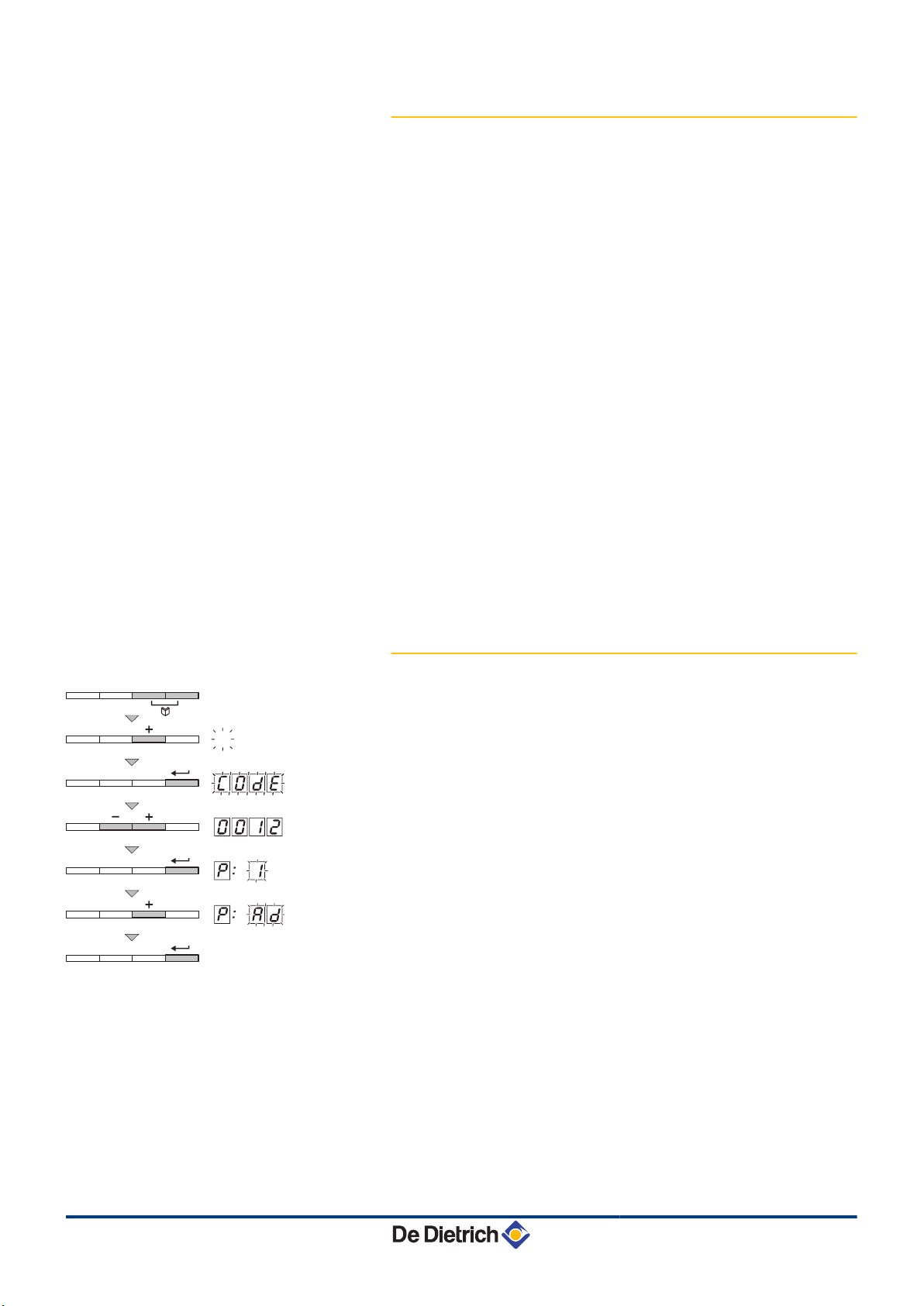
5.4.7. Carrying out an auto-detect
After removing a control PCB, an auto-detect must be carried out. To
do this, proceed as follows:
1. Press the two keys f simultaneously and then key [+] until the
symbol - flashes on the menu bar.
2. Select the installers menu using the key S.
c0de
on the display.
3. Use keys [-] or [+] to input the installer code
4. Confirm using key S.
5. Press the [+] key several times.
is displayed with 1 flashing.
p[1
p[Zd
0012
is displayed with
flashing.
6. Confirm using key j. Auto-detect is carried out.
7. The display returns to the current operating mode.
appears
.
Zd
260216 - 7600717-001-06
26
Page 28
L000168-A
2x
2x
bar
h
j
)
r
d
bar
t
h
j
5. Commissioning IniControl For C 330 / C 630 ECO
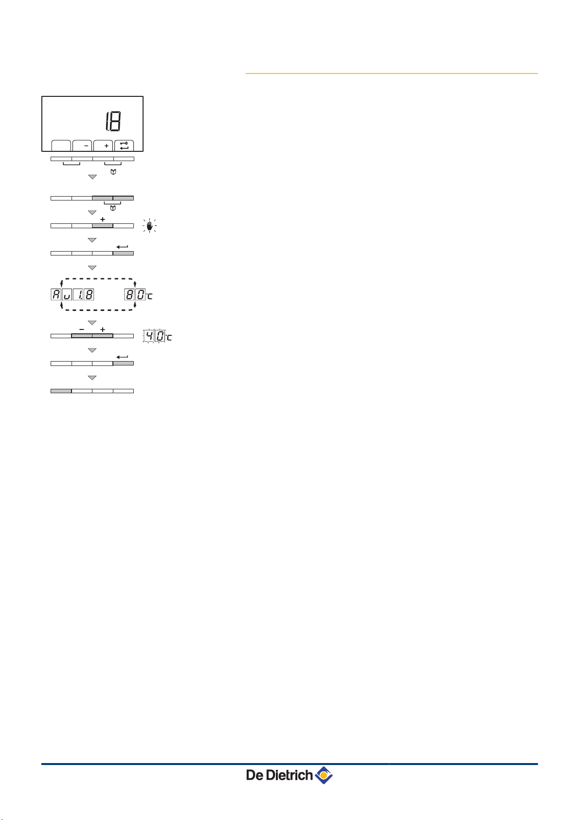
5.4.8. Setting the manual mode
In some cases it may be necessary to switch the boiler to manual
operation, For example, if the controller has not yet been
connected. The boiler can be switched to automatic or manual
operation under the symbol E. To do this, proceed as follows:
1. Press the two keys f simultaneously and then key [+] until the
symbol E flashes on the menu bar.
2. Press the S key:
or
The text
sensor is connected). The flow temperature is determined by the
internal heating curve.
or
The value of the minimum flow temperature.
3. Press the [-] or [+] key to increase this value temporarily in manual
operation.
4. Confirm the value with the S key. The boiler is now set to manual
operation.
5. Press the
mode.
with the current water pressure (only if an outside
Zv
key 2 times to return to the current operating
>
27
260216 - 7600717-001-06
Page 29
IniControl For C 330 / C 630 ECO 6. Troubleshooting
6 Troubleshooting
6.1 Shutdowns and lock-outs
For operation of the boiler C 630 ECO:
The features and instructions described are for each boiler
module.
6.1.1. General
The boiler is fitted with an electronic regulation and control unit. The
heart of the control system is a microprocessor, the Comfort
Master©, which controls the boiler and also protects the boiler. When
a failure is signalled, the boiler stops or becomes locked.
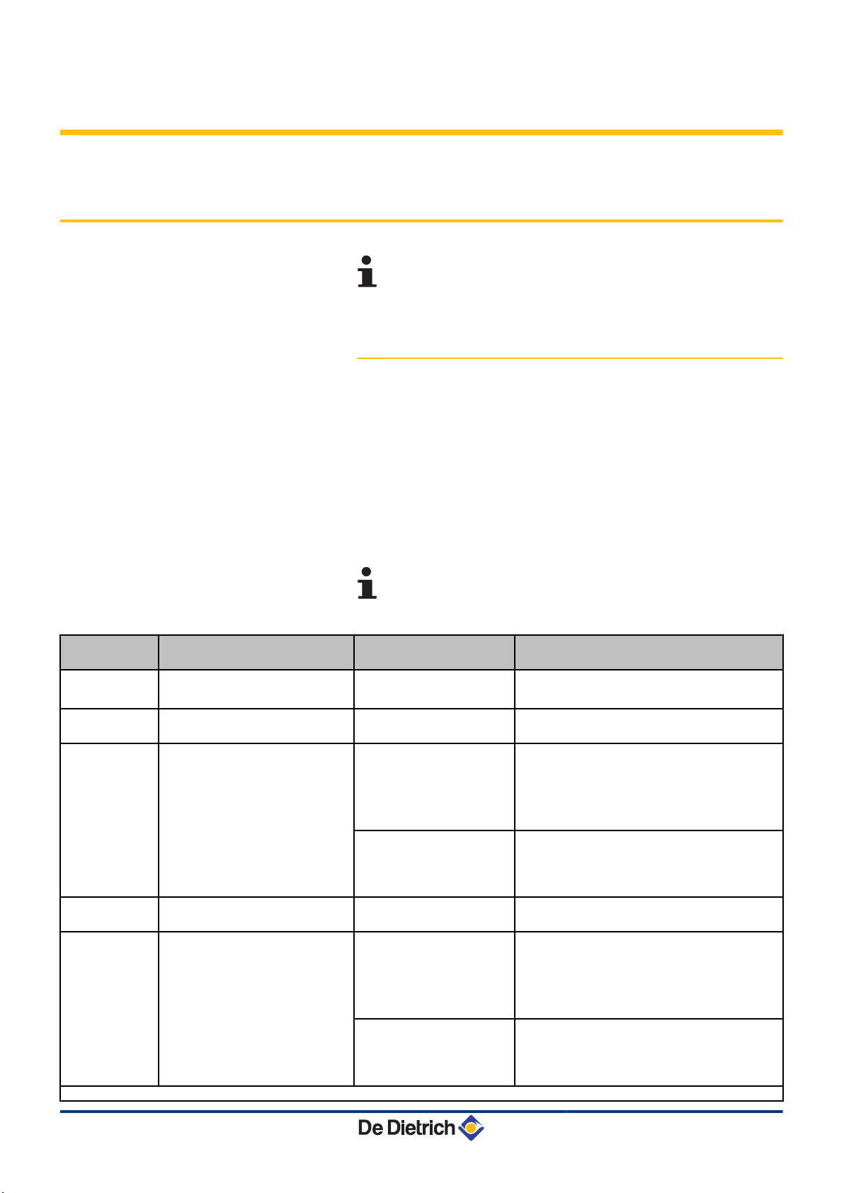
Shutdown
code
5v[0
5v[1
5v[2
5v[3
5v[4
(1) These lock-outs are not stored in the fault memory
Description Probable causes Checking / solution
Parameter error
Maximum flow temperature
exceeded
Maximum increase of the flow
temperature has been exceeded
Maximum heat exchanger
temperature exceeded
Maximum heat exchanger
temperature increase has been
exceeded
■ Blocking (Control stop)
A (temporary) blocking mode is a boiler operating function caused by
an unusual situation. In this case, the display gives a code of blocking
(code 5t[9). The boiler control will try to re-start several times.
The shutdown codes can be read out as follows
The boiler starts up again automatically when the reason
for the blocking has been removed.
The PSU PCB is incorrectly
configured
The water flow in the
installation is insufficient
The water flow in the
installation is insufficient
Sensor error
The water flow in the
installation is insufficient
The water flow in the
installation is insufficient
Sensor error
4 Reset df and dV
4 Restore parameters with Recom
4 Check the circulation (direction, pump,
valves)
4 Check the circulation (direction, pump,
valves)
4 Check the water pressure
4 Check the cleanliness of the heat
exchanger
4 Check that the sensors are operating
correctly
4 Check whether the boiler sensor has been
correctly fitted
4 Check the circulation (direction, pump,
valves)
4 Check the circulation (direction, pump,
valves)
4 Check the water pressure
4 Check the cleanliness of the heat
exchanger
4 Check that the sensors are operating
correctly
4 Check whether the boiler sensor has been
correctly fitted
260216 - 7600717-001-06
28
Page 30
6. Troubleshooting IniControl For C 330 / C 630 ECO
Shutdown
Description Probable causes Checking / solution
code
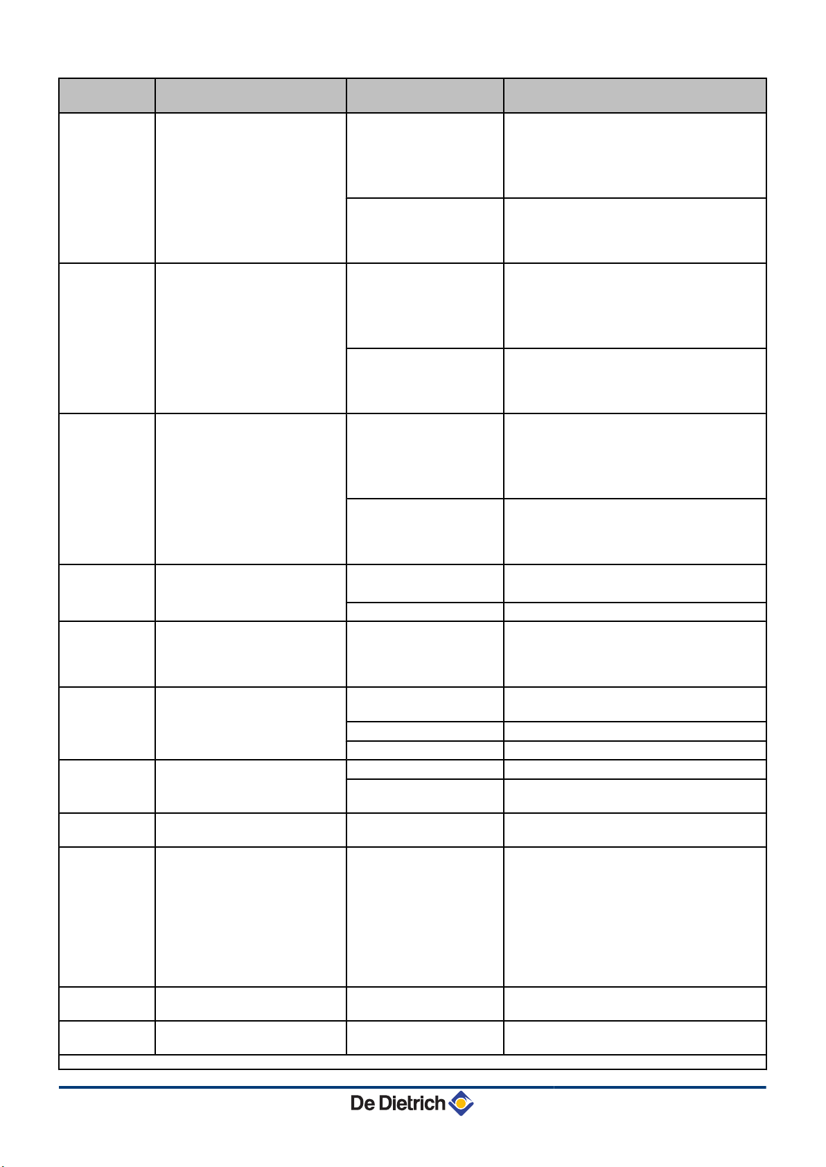
The maximum difference
5v[5
between the exchanger
temperature and the return
temperature has been exceeded
The maximum difference
between the boiler temperature
and the exchanger temperature
has been exceeded
5v[6
Maximum difference between the
flow and return temperature
exceeded
5v[7
The RL inlet on the PCU PCB
5v[8
5v[9
terminal block is open
Phase and neutral of mains
supply mixed up
The BL inlet on the PCU PCB
5v[10
terminal block is open
5v[11
5v[13
5v[14
5v[15
5v[16
5v[17
(1) These lock-outs are not stored in the fault memory
Communication error with the
SCU PCB
The water pressure is lower than
0,8 bar
Gas pressure too low
The SU PCB is not recognised Wrong SU PCB for this
(1)
The parameters saved on the
(1)
PCU PCB are impaired
The water flow in the
installation is insufficient
Sensor error
The water flow in the
installation is insufficient
Sensor error
The water flow in the
installation is insufficient
Sensor error
Parameter error
Bad connection
4 Mains supply
incorrectly wired
4 Floating or 2 phase
network
The contact connected to
the BL inlet is open
Parameter error
Bad connection
Bad connection
SCU PCB not installed in
the boiler
Not enough water in the
circuit
4 Incorrect setting of the
gas pressure switch on
the SCU PCB
4 Gas pressure too low
4 Wiring fault
4 Pressure switch is not
or badly fitted
4 Gas valve defect
boiler
Parameter error on the
PCU PCB
4 Check the circulation (direction, pump,
valves)
4 Check the water pressure
4 Check the cleanliness of the heat
exchanger
4 Check that the sensors are operating
correctly
4 Check whether the boiler sensor has been
correctly fitted
4 Check the circulation (direction, pump,
valves)
4 Check the water pressure
4 Check the cleanliness of the heat
exchanger
4 Check that the sensors are operating
correctly
4 Check whether the boiler sensor has been
correctly fitted
4 Check the circulation (direction, pump,
valves)
4 Check the water pressure
4 Check the cleanliness of the heat
exchanger
4 Check that the sensors are operating
correctly
4 Check whether the boiler sensor has been
correctly fitted
4 Reset df and dV
4 Restore parameters with Recom
4 Check the wiring
4 Invert phase and neutral
4 Set parameter p34 to 0
4 Check the contact on the BL inlet
4 Check the parameter IN.BL
4 Check the wiring
4 Check the wiring
4 Install an SCU PCB
4 Top up the installation with water
4 Check that the gas valve is fully opened
4 Checking the gas supply pressure
4 Check whether the gas pressure control
system has been correctly fitted
4 Replace the gas pressure control system
if need be
4 Check the gas valve and replace if
necessary
4 Replace the SU PCB
4 Replace the PCU PCB
29
260216 - 7600717-001-06
Page 31
IniControl For C 330 / C 630 ECO 6. Troubleshooting
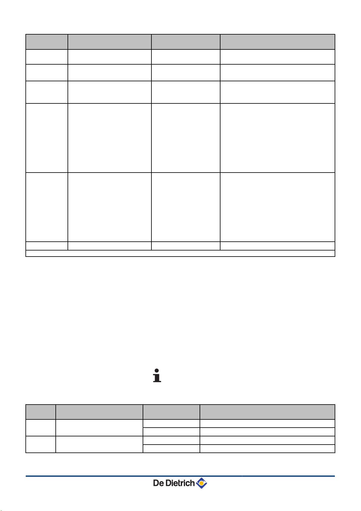
Shutdown
code
5v[18
5v[19
5v[20
5v[21
5v[22
5v[25
(1) These lock-outs are not stored in the fault memory
Description Probable causes Checking / solution
The PSU PCB is not recognised Wrong PSU PCB for this
(1)
The boiler has not been
(1)
configured
Communication error between
(1)
the PCU and SU PCBs
No flame during operation No ionization current
No flame during operation
Internal error on the SU PCB
boiler
The PSU PCB has been
changed
Bad connection
No ionization current
4 Replace the PSU PCB
4 Reset df and dV
4 Restore parameters with Recom
4 Check that the SU PCB has been correctly
put in place on the PCU PCB
4 Replace the SU PCB
4 Purge the gas supply to remove air
4 Check that the gas valve is fully opened
4 Check the supply pressure
4 Check the operation and setting of the gas
valve unit
4 Check that the air inlet and flue gas
discharge flues are not blocked
4 Check that there is no recirculation of flue
gases
4 Purge the gas supply to remove air
4 Check that the gas valve is fully opened
4 Check the supply pressure
4 Check the operation and setting of the gas
valve unit
4 Check that the air inlet and flue gas
discharge flues are not blocked
4 Check that there is no recirculation of flue
gases
4 Replace the SU PCB
Error
code
e[00
e[01
■ Blockage (Fault)
If the blocking conditions still exist after several start up attempts, the
boiler will switch into locking mode (fault). The display shows :
In a red flashing display:
4 The symbol c
4 The symbol J
4 The fault code (for example e[01)
4 Press the J key for 2 seconds. If the error code continues to
display, search for the cause in the error table and apply the
solution.
The code is important for the correct and rapid diagnosis
of the type of failure and for any technical assistance that
may be needed.
Description Probable causes Checking / solution
PSU PCB not connected Bad connection
PSU PCB faulty
The safety parameters are
incorrect
Bad connection
PSU PCB faulty
4 Check the wiring between the PCU and PSU PCBs
4 Replace the PSU PCB
4 Check the wiring between the PCU and PSU PCBs
4 Replace the PSU PCB
260216 - 7600717-001-06
30
Page 32
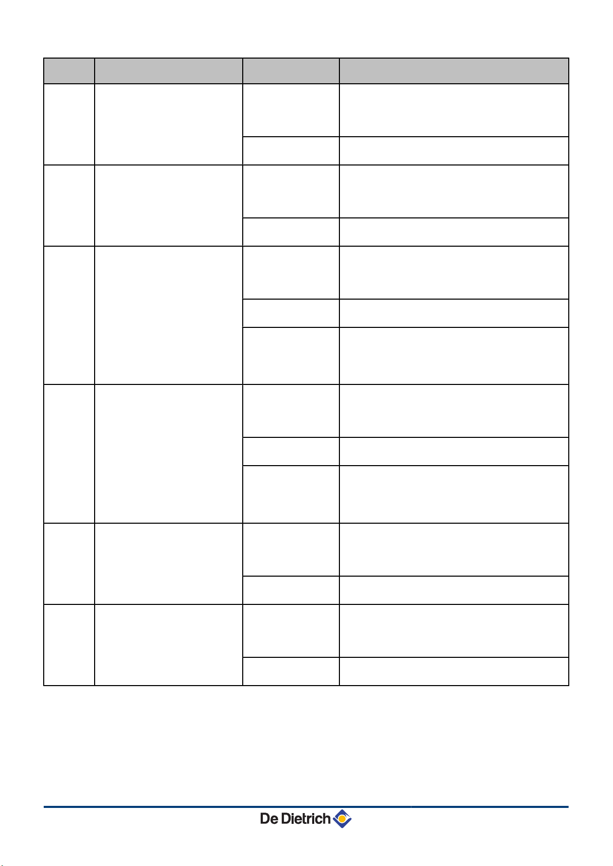
6. Troubleshooting IniControl For C 330 / C 630 ECO
Error
code
e[02
e[03
e[04
e[05
e[06
e[07
Description Probable causes Checking / solution
The exchanger sensor is short
circuited
Bad connection
4 Check the wiring between the PCU PCB and the
sensor
4 Check that the SU PCB is correctly in place
4 Check that the sensor has been correctly fitted
Sensor fault
4 Check the Ohmic value of the sensor
4 Replace the sensor if necessary
The exchanger sensor is on an
open circuit
Bad connection
4 Check the wiring between the PCU PCB and the
sensor
4 Check that the SU PCB is correctly in place
4 Check that the sensor has been correctly fitted
Sensor fault
4 Check the Ohmic value of the sensor
4 Replace the sensor if necessary
Temperature of heat exchanger
too low
Bad connection
4 Check the wiring between the PCU PCB and the
sensor
4 Check that the SU PCB is correctly in place
4 Check that the sensor has been correctly fitted
Sensor fault
4 Check the Ohmic value of the sensor
4 Replace the sensor if necessary
No water circulation
4 Vent the air in the heating system
4 Check the circulation (direction, pump, valves)
4 Check the water pressure
4 Check the cleanliness of the heat exchanger
Exchanger temperature too high Bad connection
4 Check the wiring between the PCU PCB and the
sensor
4 Check that the SU PCB is correctly in place
4 Check that the sensor has been correctly fitted
Sensor fault
4 Check the Ohmic value of the sensor
4 Replace the sensor if necessary
No water circulation
4 Vent the air in the heating system
4 Check the circulation (direction, pump, valves)
4 Check the water pressure
4 Check the cleanliness of the heat exchanger
The return temperature sensor has
short-circuited
Bad connection
4 Check the wiring between the PCU PCB and the
sensor
4 Check that the SU PCB is correctly in place
4 Check that the sensor has been correctly fitted
Sensor fault
4 Check the Ohmic value of the sensor
4 Replace the sensor if necessary
The return temperature sensor is
on an open circuit
Bad connection
4 Check the wiring between the PCU PCB and the
sensor
4 Check that the SU PCB is correctly in place
4 Check that the sensor has been correctly fitted
Sensor fault
4 Check the Ohmic value of the sensor
4 Replace the sensor if necessary
31
260216 - 7600717-001-06
Page 33
IniControl For C 330 / C 630 ECO 6. Troubleshooting
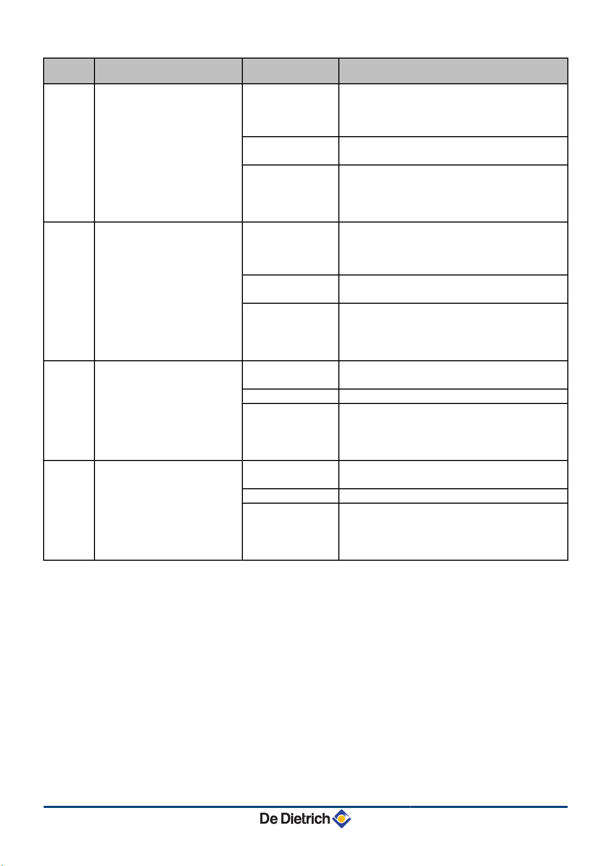
Error
code
e[08
e[09
e[10
e[11
Description Probable causes Checking / solution
Return temperature too low Bad connection
4 Check the wiring between the PCU PCB and the
sensor
4 Check that the SU PCB is correctly in place
4 Check that the sensor has been correctly fitted
Sensor fault
4 Check the Ohmic value of the sensor
4 Replace the sensor if necessary
No water circulation
4 Vent the air in the heating system
4 Check the circulation (direction, pump, valves)
4 Check the water pressure
4 Check the cleanliness of the heat exchanger
Return temperature too high Bad connection
4 Check the wiring between the PCU PCB and the
sensor
4 Check that the SU PCB is correctly in place
4 Check that the sensor has been correctly fitted
Sensor fault
4 Check the Ohmic value of the sensor
4 Replace the sensor if necessary
No water circulation
4 Vent the air in the heating system
4 Check the circulation (direction, pump, valves)
4 Check the water pressure
4 Check the cleanliness of the heat exchanger
Difference insufficient between the
exchanger temperature and the
return temperature
Sensor fault
Bad connection
No water circulation
4 Check the Ohmic value of the sensor
4 Replace the sensor if necessary
4 Check that the sensor has been correctly fitted
4 Vent the air in the heating system
4 Check the circulation (direction, pump, valves)
4 Check the water pressure
4 Check the cleanliness of the heat exchanger
Difference between the return
temperature and the exchanger
temperature too big
Sensor fault
Bad connection
No water circulation
4 Check the Ohmic value of the sensor
4 Replace the sensor if necessary
4 Check that the sensor has been correctly fitted
4 Vent the air in the heating system
4 Check the circulation (direction, pump, valves)
4 Check the water pressure
4 Check the cleanliness of the heat exchanger
260216 - 7600717-001-06
32
Page 34
6. Troubleshooting IniControl For C 330 / C 630 ECO
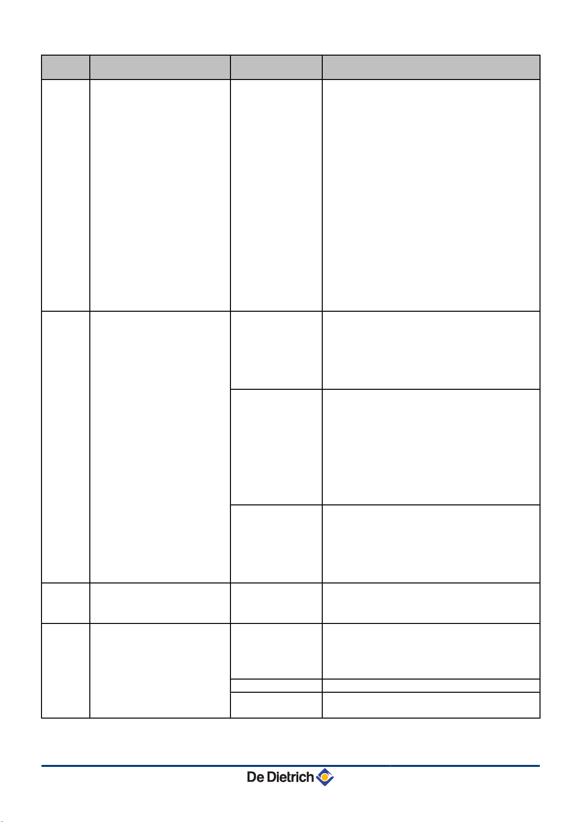
Error
code
e[12
e[14
e[15
e[16
Description Probable causes Checking / solution
4 Check that the air inlet and flue gas discharge flues
are not blocked
4 Check that condensate has been removed and the
cleanliness of the siphon
4 Check the cleanliness of the heat exchanger (Flue
4 Maximum boiler temperature
exceeded (STB thermostat
maximum)
4 Air differential pressure switch
has been triggered
4 Air inlet or flue
gas discharge
blocked
4 Bad connection
4 No water
circulation
4 Failure of the
safety device
4 Sensor not or
badly connected
gas dimensions)
4 Check the wiring between the PCU PCB and the
STB
4 Check that the SU PCB is correctly in place
4 Check the electrical continuity of the STB
4 Check whether the STB has been correctly fitted
4 Check that the sensor has been correctly fitted
4 Check for correct operation
4 Remove the air from the installation
4 Check the circulation (direction, pump, valves)
4 Check the water pressure
4 Check the cleanliness of the heat exchanger
4 Check that the heating pump is operating correctly
4 Check the wiring between the PCU PCB and the
ignition transformer
4 Check that the SU PCB is correctly in place
No ignition
4 Check the ionization/ignition electrode
4 Check the earthing
4 SU PCB faulty: Change the PCB
4 Vent the gas flues
4 Check that the gas valve is fully opened
4 Checking the gas supply pressure
5 burner start-up failures
Ignition arc, but no
flame formation
4 Check the operation and setting of the gas valve
unit
4 Check that the air inlet and flue gas discharge flues
are not blocked
4 Check the wiring on the gas valve unit
4 SU PCB faulty: Change the PCB
4 Check that the gas valve is fully opened
Presence of the flame
but insufficient
ionization (<3 µA)
4 Checking the gas supply pressure
4 Check the ionization/ignition electrode
4 Check the earthing
4 Check the wiring on the ionization/ignition
electrode
The cyclical leak proofing kit (CCE)
has detected a leak
Reset the box
4 Check that the gas valve is fully opened
4 Checking the gas supply pressure
4 Check the gas valve and replace if necessary
Detection of a parasite flame Ionization current
4 Check the ionization/ignition electrode
present even though
there is no flame
Ignition transformer
defective
Gas valve defect
The burner remains
4 Check the gas valve and replace if necessary
4 Set the CO
2
very hot: CO2 too high
33
260216 - 7600717-001-06
Page 35
IniControl For C 330 / C 630 ECO 6. Troubleshooting
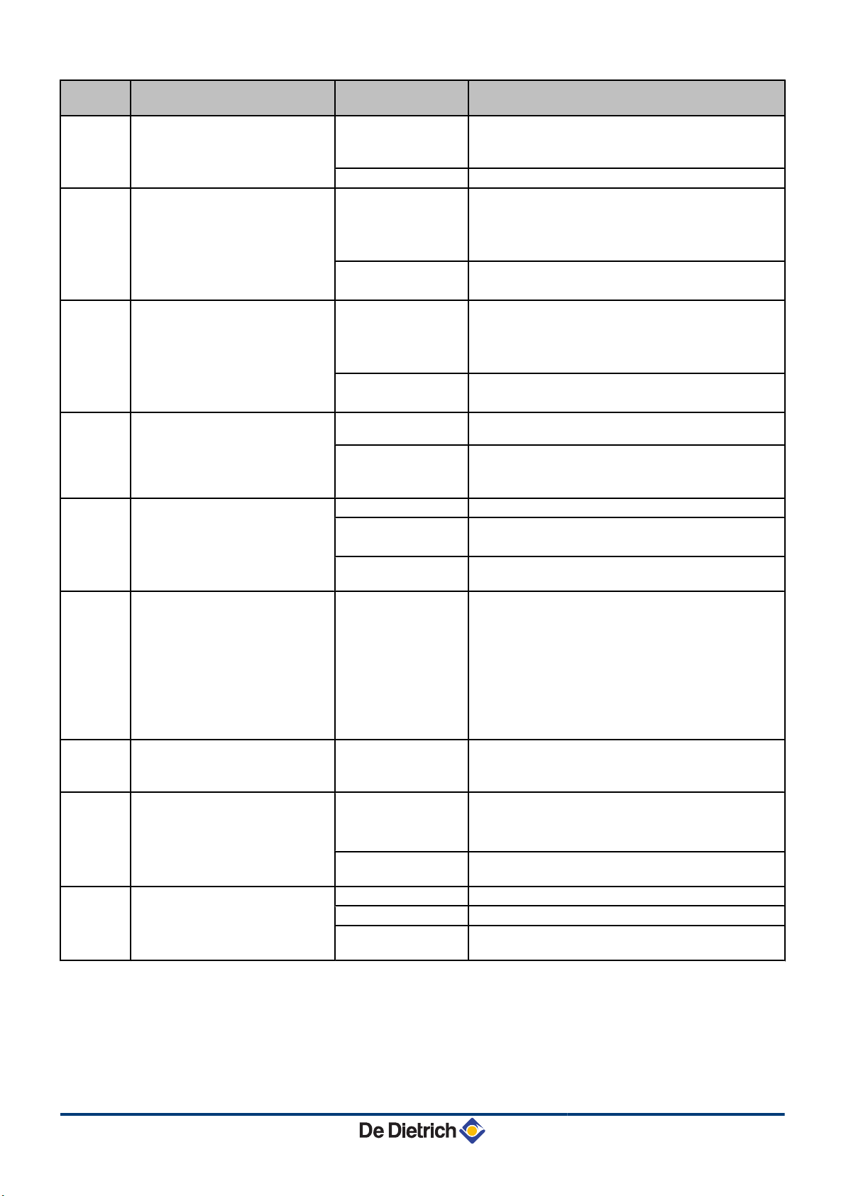
Error
code
e[17
e[32
e[33
e[34
e[35
e[36
e[37
e[38
e[39
Description Probable causes Checking / solution
Problem on the gas valve Bad connection
4 Check the wiring between the PCU PCB and the
gas valve
4 Check that the SU PCB is correctly in place
The boiler flow sensor has shortcircuited
SU PCB faulty
Bad connection
4 Inspect the SU PCB and replace it if need be
4 Check the wiring between the PCU PCB and the
sensor
4 Check that the SU PCB is correctly in place
4 Check that the sensor has been correctly fitted
Sensor fault
4 Check the Ohmic value of the sensor
4 Replace the sensor if necessary
The boiler flow sensor is on an
open circuit
Bad connection
4 Check the wiring between the PCU PCB and the
sensor
4 Check that the SU PCB is correctly in place
4 Check that the sensor has been correctly fitted
Sensor fault
4 Check the Ohmic value of the sensor
4 Replace the sensor if necessary
The fan is not running at the right
speed
Bad connection
Fan defective
4 Check the wiring between the PCU PCB and the
fan
4 Check for adequate draw on the chimney
connection
4 Replace the fan if need be
Bad connection
Sensor fault
Flow and return reversed
Water circulation
4 Check that the sensor has been correctly fitted
4 Check the Ohmic value of the sensors
4 Replace the sensor if necessary
4 Check the circulation (direction, pump, valves)
direction reversed
The flame went out more than 5
times in 24 hours while the burner
was operating
No ionization current
4 Purge the gas supply to remove air
4 Check that the gas valve is fully opened
4 Checking the gas supply pressure
4 Check the operation and setting of the gas valve
unit
4 Check that the air inlet and flue gas discharge flues
are not blocked
4 Check that there is no recirculation of flue gases
Communication failure with the
SU PCB
Bad connection
4 Check whether the SU PCB has been correctly
fitted into the connector on the PCU PCB
4 Change the SU PCB
Bad connection
Communication error with the
SCU PCB
SCU PCB not
4 Check the wiring between the PCU and SCU PCBs
4 Reset df and dV
4 Restore parameters with Recom
4 Replace the SCU PCB
connected or faulty
Shutdown input in locked-out
mode
Bad connection
External cause
Parameter incorrectly
4 Check the wiring
4 Check the device connected to the BL contact
4 Check the parameter IN.BL
set
260216 - 7600717-001-06
34
Page 36
L000169-A
4x
2x
h
j
h
j
h
j
6. Troubleshooting IniControl For C 330 / C 630 ECO
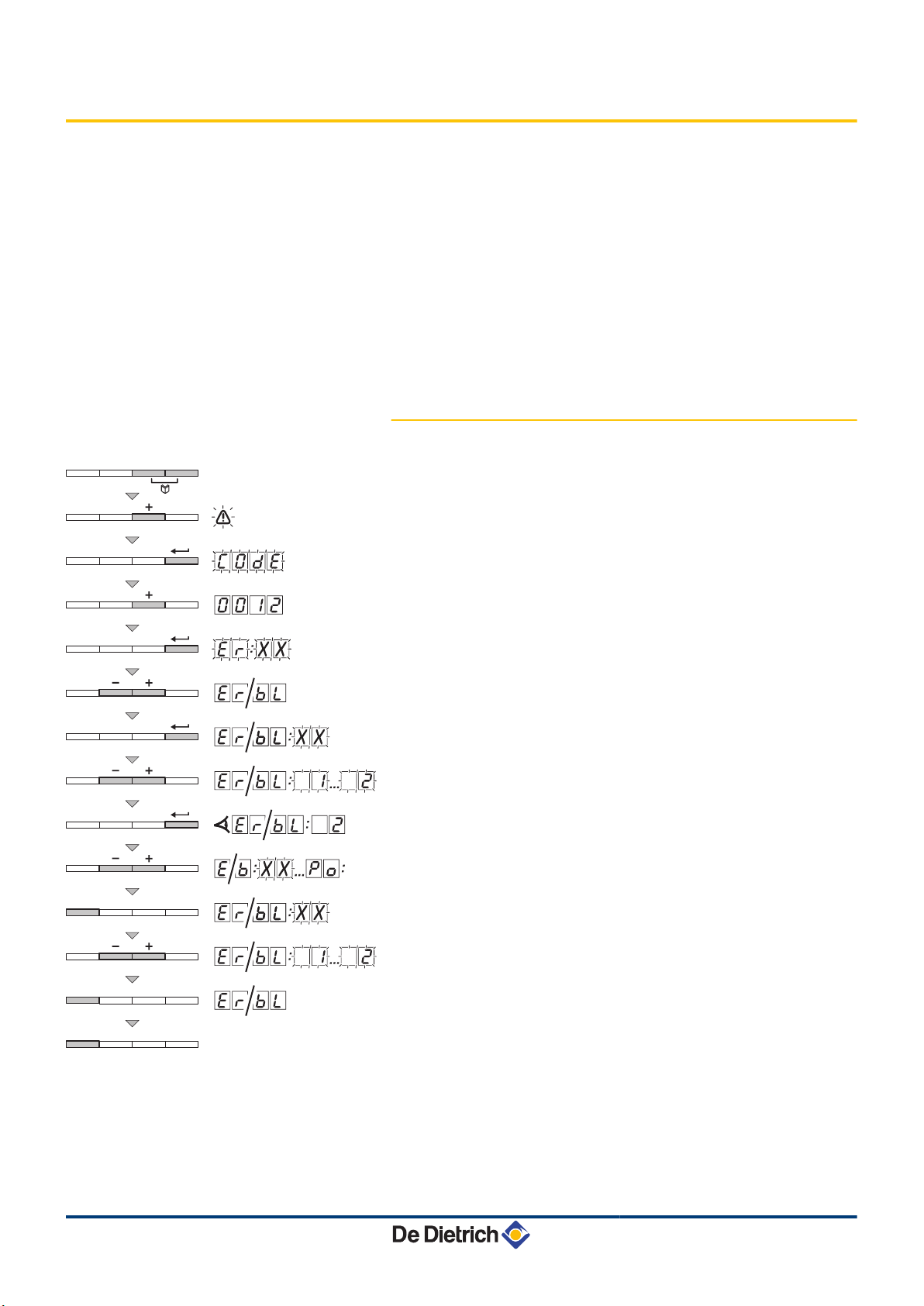
6.2 Error memory
The boiler control is equipped with an error memory. The last 16 errors
encountered are recorded in this memory.
In addition to the error codes, the following data are also saved:
4 Number of times that the error occured: (MK[xx).
4 Boiler operating mode selected (5t[xx).
4 The flow temperature (t1[xx) and the return temperature
(t2[xx) when the error occured.
To view the error memory, you first have to enter access code
0012.
6.2.1. Error readout memorised
1. Press the two keys f simultaneously and then key [+] until the
symbol a flashes on the menu bar.
2. Select the installers menu using the key S.
c0de
on the display.
3. Use keys [-] or [+] to input the installer code
4. Press the S key.
er[xx
appears on the display.
0012
5. The fault list or shutdown list can be displayed by pressing the
[-] or [+] key.
6. Confirm using key S.
er[xx
is displayed with
flashing = Last error which occured, For example
7. Use the [-] or [+] key to scroll through the faults or shutdowns.
8. Press the S key to display the details of the faults or shutdowns.
9. Press the j key to interrupt the display cycle.
displayed with
flashing = Last error which occured.
xx
er[xx
10.Press the j key to show the fault list or shutdown list.
11.Press 2 times on the key j to exit the error memory.
xx
K2
appears
.
.
is
35
260216 - 7600717-001-06
Page 37
L000170-A
3x
4x
h
j
IniControl For C 330 / C 630 ECO 6. Troubleshooting
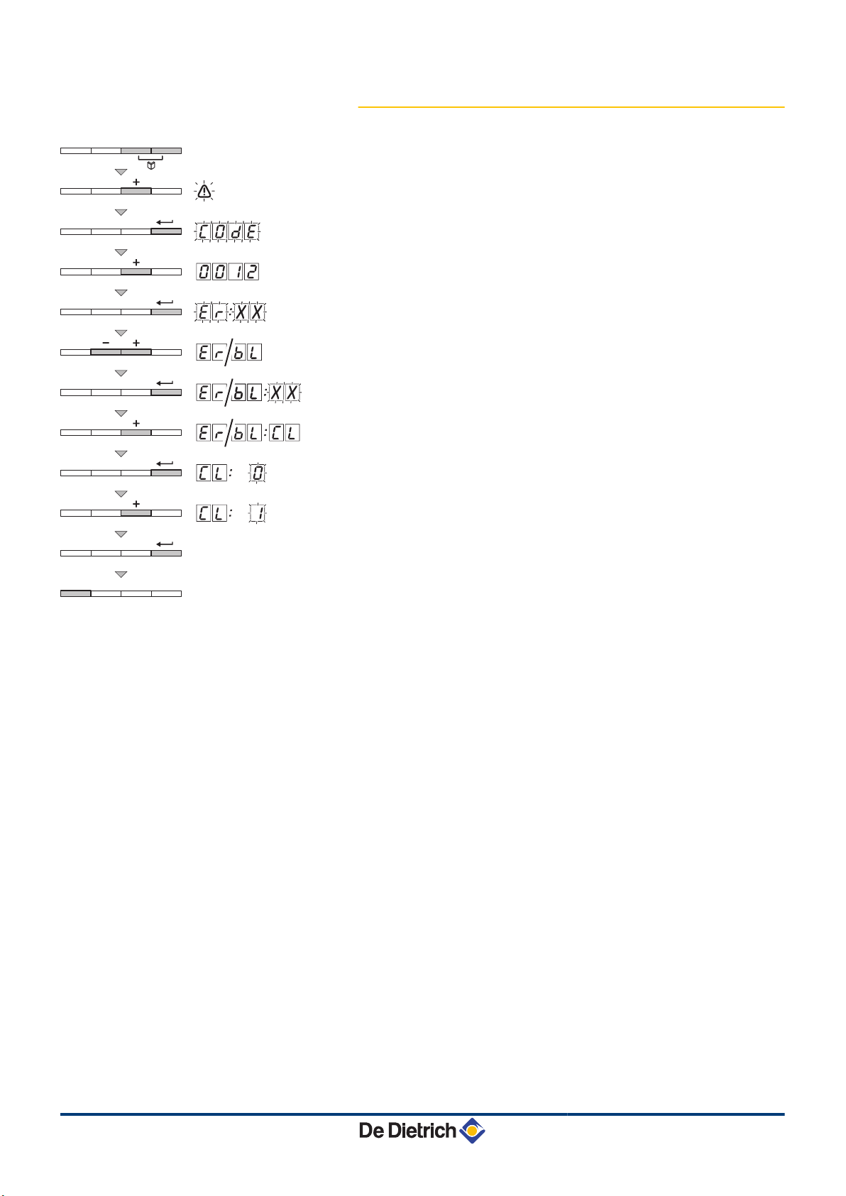
6.2.2. Deletion of the error display
1. Press the two keys f simultaneously and then key [+] until the
symbol a flashes on the menu bar.
2. Select the installers menu using the key S.
c0de
on the display.
3. Use keys [-] or [+] to input the installer code
4. Press the S key.
er[xx
appears on the display.
0012
5. The fault list or shutdown list can be displayed by pressing the
[-] or [+] key.
6. Confirm using key S.
er[xx
7. Press the [+] key several times until
is displayed with
er[cl
is displayed on the
screen.
8. Press the S key.
cl[0
is displayed with 0 flashing.
9. Press key [+] to modify the value to 1.
10.Press the S key to delete the errors from the error memory.
11.Press 3 times on the key j to exit the error memory.
xx
appears
.
flashing.
260216 - 7600717-001-06
36
Page 38

Page 39

Page 40
AD001NU-AJ
DUEDI S.r.l.
DE DIETRICH SERVICE
BDR Thermea (Czech republic) s.r.o
www.duediclima.it
www.dedietrich.cz
Distributore Ufficiale Esclusivo
De Dietrich-Thermique Italia
www.dedietrich-heiztechnik.com
Freecall 0800 / 201608
Jeseniova 2770/56
130 00 Praha 3
+49 (0)25 72 / 9161-0
+49 (0)25 72 / 9161-102
Via Passatore, 12 - 12010
San Defendente di Cervasca
CUNEO
+39 0171 857170
+39 0171 687875
[email protected]
+420 271 001 627
[email protected]
IT
DE DIETRICH THERMIQUE Iberia S.L.U.
www.dedietrich-calefaccion.es
C/Salvador Espriu, 11
08908 L’HOSPITALET de LLOBREGAT
+34 935 475 850
[email protected]
ES
129164, Россия, г. Москва
Зубарев переулок, д. 15/1
Бизнес-центр «Чайка Плаза»,
офис 309
+7 (495) 221-31-51
CZ
DE DIETRICH THERMIQUE S.A.S
7600717- 001- 06
DEDIETRICH THERMIQUE
57,ruedelaGareF-67580MERTZWILLER-BP 30
© Copyright
All technical and technological information contained in these technical instructions,
as well as any drawings and technical descriptions supplied, remain our property
and shall not be multiplied without our prior consent in writing.
260216
 Loading...