

Page 1
EN
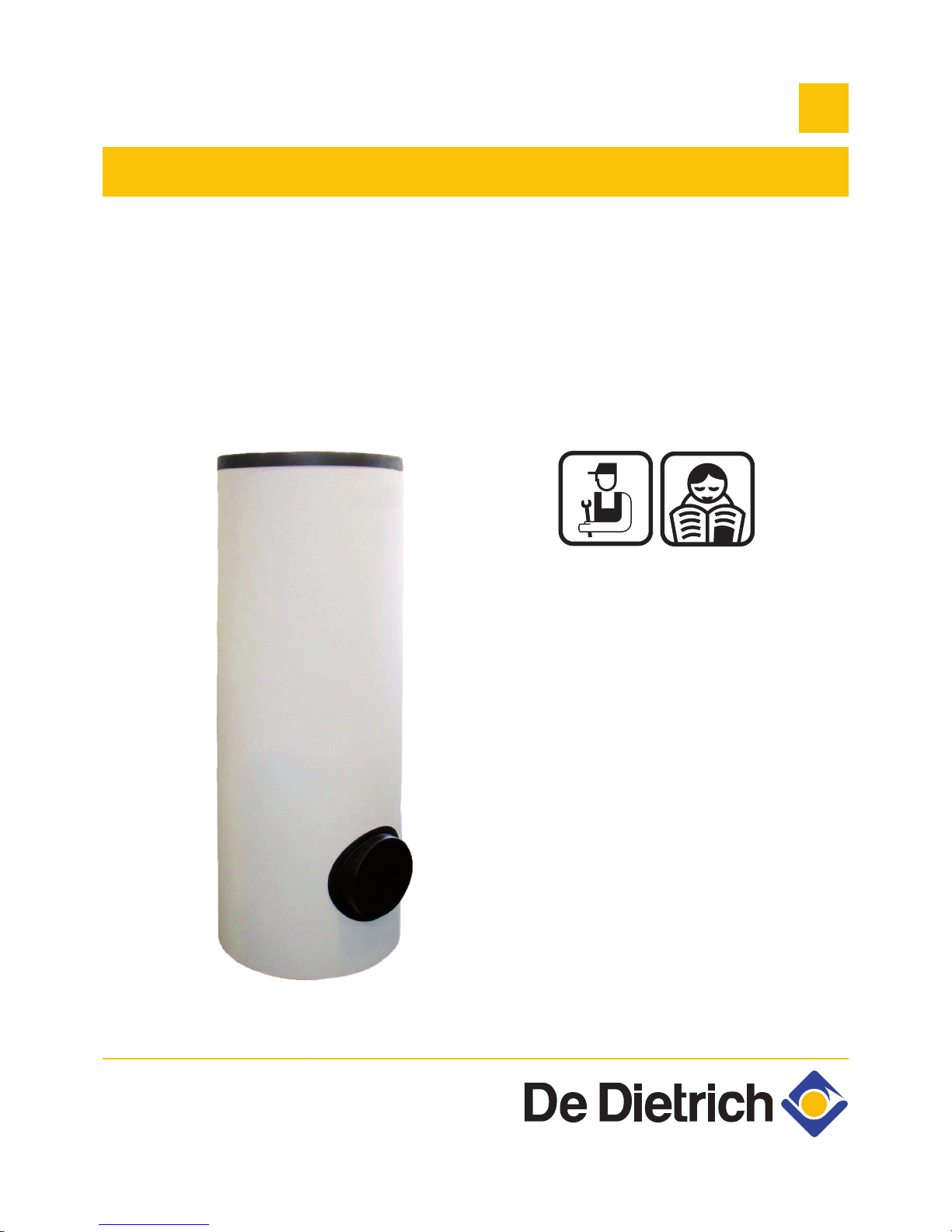
Independent domestic hot water tanks
BL 150...500
M001635-B
Installation, User
and Service
Manual
300019417-001-C
Page 2

Contents
1 Introduction ................................................................................................4
1.1 Used symbols .......................................................4
1.2 Abbreviations ........................................................4
1.3 General ..................................................................4
1.3.1 Manufacturer's liability .............................................4
1.3.2 Installer's liability .....................................................5
1.3.3 User's liability ..........................................................5
1.4 Homologations ......................................................6
1.4.1 Certifications ...........................................................6
1.4.2 Directive 97/23/EC ..................................................6
1.4.3 Factory test .............................................................6
2 Safety instructions and recommendations ..............................................7
2.1 Safety instructions ...............................................7
2.2 Recommendations ................................................7
3 Technical description ................................................................................8
3.1 General description ..............................................8
3.2 Technical characteristics .....................................8
3.2.1 Characteristics of the DHW calorifier ......................8
3.2.2 Specifications of the DHW sensor ...........................9
4 Installation ................................................................................................10
4.1 Regulations governing installation ...................10
4.2 Package list .........................................................10
4.2.1 Standard delivery ..................................................10
4.2.2 Accessories ...........................................................10
4.3 Choice of the location ........................................11
4.3.1 Data plate ..............................................................11
4.3.2 Location of the appliance ......................................11
4.3.3 Main dimensions ...................................................12
4.4 Levelling ..............................................................13
4.5 Hydraulic installation diagram ..........................13
4.5.1 Safety unit (For France ) .......................................14
1
01/03/2011 - 300019417-001-C
Page 3

4.6 Hydraulic connections .......................................15
4.6.1 Hydraulic connection of the primary circuit (exchanger
circuit) ....................................................................15
4.6.2 Connecting the tank to the domestic water circuit
(secondary circuit) .................................................15
4.7 Electrical connections ........................................17
4.7.1 Recommendations ................................................17
4.7.2 Fitting the DHW sensor .........................................18
5 Commissioning ........................................................................................19
5.1 Putting the appliance into operation ................19
6 Checking and maintenance .....................................................................20
6.1 General instructions ...........................................20
6.2 Checking the magnesium anode .......................20
6.3 Safety valve or safety unit .................................20
6.4 Cleaning the casing material .............................20
6.5 Replacing the magnesium anode and
descaling .............................................................20
6.6 Maintenance form ...............................................22
7 Spare parts ................................................................................................23
7.1 General ................................................................23
7.2 Spare parts ..........................................................23
7.2.1 Domestic hot water tanks ......................................24
7.2.2 Options ..................................................................29
8 Warranty ....................................................................................................34
8.1 General ................................................................34
8.2 Warranty terms ...................................................34
Contents
2
01/03/2011 - 300019417-001-C
Page 4

3
01/03/2011 - 300019417-001-C
Page 5
1 Introduction
1.1 Used symbols
In these instructions, various danger levels are employed to draw the
user's attention to particular information. In so doing, we wish to
safeguard the user's safety, obviate hazards and guarantee correct
operation of the appliance.
DANGER
Risk of a dangerous situation causing serious physical
injury.
WARNING
Risk of a dangerous situation causing slight physical
injury.
CAUTION
Risk of material damage.
Signals important information.
¼ Signals a referral to other instructions or other pages in the
instructions.
1.2 Abbreviations
4 CFC: Chlorofluorocarbon
4 DHW: Domestic hot water
1.3 General
1.3.1. Manufacturer's liability
Our products are manufactured in compliance with the requirements
of the various applicable European Directives. They are therefore
delivered with [ marking and all relevant documentation.
BL 150...500
1. Introduction
01/03/2011 - 300019417-001-C
4
Page 6

In the interest of customers, we are continuously endeavouring to
make improvements in product quality. All the specifications stated in
this document are therefore subject to change without notice.
Our liability as the manufacturer may not be invoked in the following
cases:
4 Failure to abide by the instructions on using the appliance.
4 Faulty or insufficient maintenance of the appliance.
4 Failure to abide by the instructions on installing the appliance.
1.3.2. Installer's liability
The installer is responsible for the installation and inital start up of the
appliance. The installer must respect the following instructions:
4 Read and follow the instructions given in the manuals provided
with the appliance.
4 Carry out installation in compliance with the prevailing legislation
and standards.
4 Perform the initial start up and carry out any checks necessary.
4 Explain the installation to the user.
4 If a maintenance is necessary, warn the user of the obligation to
check the appliance and maintain it in good working order.
4 Give all the instruction manuals to the user.
1.3.3. User's liability
To guarantee optimum operation of the appliance, the user must
respect the following instructions:
4 Read and follow the instructions given in the manuals provided
with the appliance.
4 Call on qualified professionals to carry out installation and initial
start up.
4 Get your fitter to explain your installation to you.
4 Have the required checks and services done.
4 Keep the instruction manuals in good condition close to the
appliance.
This appliance is not intended to be used by persons (including
children) whose physcial, sensory or mental capacity is impaired or
persons with no experience or knowledge, unless they have the
benefit, through the intermediary of a person responsible for their
safety, of supervision or prior instructions regarding use of the
appliance. Care should be taken to ensure that children do not play
with the appliance.
1. Introduction
BL 150...500
5
01/03/2011 - 300019417-001-C
Page 7

1.4 Homologations
1.4.1. Certifications
This product complies to the requirements to the european directives
and following standards:
4 2006/95/EC Low Voltage Directive.
Reference Standard: EN 60.335.1.
4 2004/108/EC Electromagnetic Compatibility Directive.
Reference Standards: EN 50.081.1, EN 50.082.1, EN 55.014
1.4.2. Directive 97/23/EC
This product conforms to the requirements of european directive 97 /
23 / EC, article 3, paragraph 3, on pressure equipment.
1.4.3. Factory test
Before leaving the factory, each appliance is tested for the following:
4 Water tightness
4 Air tightness
4 Electrical safety.
BL 150...500 1. Introduction
01/03/2011 - 300019417-001-C
6
Page 8
2 Safety instructions and
recommendations
2.1 Safety instructions
CAUTION
Before any work, switch off the mains supply to the
appliance.
CAUTION
In order to limit the risk of being scalded, the installation of
a thermostatic mixing valve on the domestic hot water flow
piping is compulsory.
2.2 Recommendations
CAUTION
Do not neglect to service the appliance. Service the
appliance regularly to ensure that it operates correctly.
WARNING
Only qualified professionals are authorised to work on the
appliance and the instalation.
WARNING
Heating water and domestic water must not come into
contact with each other. Domestic water must not circulate
via the exchanger.
4 To take advantage of the guarantee, no modifications must be
made to the appliance.
4 To reduce heat losses as much as possible, insulate the pipes.
Casing components
Only remove the casing for maintenance and repair operations. Put
the casing back in place after maintenance and repair operations.
Instructions stickers
The instructions and warnings affixed to the appliance must never be
removed or covered and must remain legible during the entire lifespan
of the appliance. Immediately replace damaged or illegible
instructions and warning stickers.
2. Safety instructions and recommendations
BL 150...500
7
01/03/2011 - 300019417-001-C
Page 9
3 Technical description
3.1 General description
BL 150...500 are high performance independent domestic hot water
tanks.
DHW calorifiers BL 150...500 can be connected to central heating
boilers used for heating domestic hot water.
Main parts:
4 The tanks are made of high quality steel lined with food quality
standard enamel vitrified at 850°C, which protects the tank from
corrosion.
4 The heat exchanger welded into the tank is made of smooth
tubing, the external surface of which, which is in contact with
domestic water, is enamelled.
4 The appliance is insulated by CFC-free polyurethane foam, which
reduces heat losses to a minimum
4 The insulating material can be easily detached from the tank. This
measure facilitates the recycling of materials.
4 The tank is protected against corrosion by a magnesium anode
which should be checked every 2 years and replaced if need be.
The tanks with the greatest capacity (BL 300, BL 400, BL 500) are
fitted with 2 protection anodes.
3.2 Technical characteristics
3.2.1. Characteristics of the DHW calorifier
BL 150 BL 200 BL 300 BL 400 BL 500
Primary circuit (heating water)
Maximum operating temperature °C 90 90 90 90 90
Maximum operating pressure bar 10 10 10 10 10
Exchanger capacity l 4.9 5.7 8.0 11.2 14.9
Exchange surface
m
2
0.72 0.84 1.19 1.67 2.22
Secondary circuit (domestic water)
Maximum operating temperature °C 90 90 90 90 90
Maximum operating pressure bar 10 10 10 10 10
Water content l 150 200 300 400 500
Weight
Shipping weight - DHW tank package kg 88.5 107.5 155 238 290
Performances related to the boiler type
(1) Primary temperature: 80 °C - Domestic cold water inlet: 10 °C - Domestic hot water outlet: 45 °C - Primary flow rate: 3 m3/h
(2) Primary temperature: 80 °C - Domestic cold water inlet: 10 °C - Domestic hot water outlet: 40 °C - Domestic hot water storage: 60 °C
BL 150...500 3. Technical description
01/03/2011 - 300019417-001-C
8
Page 10
BL 150 BL 200 BL 300 BL 400 BL 500
Power exchanged
(1)
kW 28 33 44 55 70
Flow per hour (∆T = 35 °C)
(1)
l/h 690 810 1080 1350 1720
Specific flow (∆T = 30 °C) (10 minutes)
(2)
l/h 220 325 510 620 780
(1) Primary temperature: 80 °C - Domestic cold water inlet: 10 °C - Domestic hot water outlet: 45 °C - Primary flow rate: 3 m3/h
(2) Primary temperature: 80 °C - Domestic cold water inlet: 10 °C - Domestic hot water outlet: 40 °C - Domestic hot water storage: 60 °C
3.2.2. Specifications of the DHW sensor
Temperature in °C 10 20 25 30 40 50 60 70 80
Resistance in ohm 19691 12474 10000 8080 5372 3661 2536 1794 1290
3. Technical description BL 150...500
9
01/03/2011 - 300019417-001-C
Page 11

4 Installation
4.1 Regulations governing installation
CAUTION
Installation of the appliance must be done by a qualified
engineer in accordance with prevailing local and national
regulations.
CAUTION
France: The installation must comply in all matters to the
standards and rules which govern the work and
interventions in individual and collective homes, and other
constructions.
4.2 Package list
4.2.1. Standard delivery
The delivery includes:
4 One DHW tank.
4 One installation, use and service manual.
BL 150 BL 200 BL 300 BL 400 BL 500
DHW tank package
EC 441 EC 442 EC 443 EC 444 EC 445
4.2.2. Accessories
Various options are available depending on the configuration of the
installation:
BL 150 BL 200 BL 300 BL 400 BL 500
Impressed current anode
AJ 38 AJ 38 AJ 38 AM 7 AM 7
Titanium anode
(1)
EC 414 EC 414 - - -
Single phase shielded resistor
2.2 kW
EC 410 - - - -
Multi-voltage shielded resistor
3.3 kW
- - EC 412 - -
(1) The titanium anode can only be fitted to the DHW tank if this is connected to a boiler equipped with a Diematic 3 control panel which
incorporates the TAS ® function.
(2) The EG 88 steatite heating resistance must be accompanied by the installation of the AJ 38 impressed current anode in the top buffer tank
in order to ensure adequate protection of the tank against corrosion.
BL 150...500 4. Installation
01/03/2011 - 300019417-001-C
10
Page 12
BL 150 BL 200 BL 300 BL 400 BL 500
Multi-voltage shielded resistor
4.5 kW
- - - EC 413 EC 413
Multi-voltage steatite heating
resistance 2.4 kW
- EC 411 - - -
Multi-voltage steatite heating
resistance 3 kW
- -
EG 88
(2)
- -
SLA2 control system for load
pump
EC 320 EC 320 EC 320 EC 320 EC 320
(1) The titanium anode can only be fitted to the DHW tank if this is connected to a boiler equipped with a Diematic 3 control panel which
incorporates the TAS ® function.
(2) The EG 88 steatite heating resistance must be accompanied by the installation of the AJ 38 impressed current anode in the top buffer tank
in order to ensure adequate protection of the tank against corrosion.
WARNING
4 The impressed current anode and the shielded
electrical resistor cannot be fitted simultaneously.
4 Respect the recommended anode / electrical resistor
combinations as the electrical resistor is combined
with a magnesium anode which, with the anode in the
top section already in place, is calculated to protect
the enamelled tank correctly.
4.3 Choice of the location
4.3.1. Data plate
The nameplate affixed to the tank provides important information
regarding the appliance: serial number, model, etc.
CAUTION
The rating plate must be accessible at all times.
4.3.2. Location of the appliance
CAUTION
Put the appliance in a frost-free location.
4 Place the appliance as close as possible to draw-off points in order
to minimise energy losses through the pipes.
4 Place the appliance on a base frame to facilitate cleaning of the
premises.
4. Installation
BL 150...500
11
01/03/2011 - 300019417-001-C
Page 13

4.3.3. Main dimensions
M001637-C
Ø G
BL 150BL 200-500
H
A
30
B
C
D
E
F
J
1
7
7
7
11
11
2
3
4
5
6
1
BL 200
A
Domestic hot water outlet (G 1)
Z
Exchanger inlet (G 1)
E
Circulation (G ¾)
R
Domestic cold water inlet (G 1)
BL 150 - BL 200 - BL 300: Drain opening
T
Exchanger outlet (G 1)
Y
Drain opening (G 1)
except BL 150 - BL 200 - BL 300
U
Magnesium anode
BL 200: no anode on the side trap
a
Domestic hot water sensor
(1) : Adjustable feet
G : Exterior cylindrical threading, sealed by sheet gasket
BL 150 BL 200 BL 300 BL 400 BL 500
A
- - - 68 68
B
188 188 188 211 206
C
268 268 268 302 304
D
493 408 543 804 791
E
588 633 768 991 986
F
- 948 1488 1381 1468
G (Ø)
600 600 600 750 750
H
900 1180 1754 1589 1725
J
941 - - - -
BL 150...500 4. Installation
01/03/2011 - 300019417-001-C
12
Page 14

4.4 Levelling
The DHW tank is levelled using the feet (delivered in the instructions
pack) to be screwed to the bottom of the DHW tank:
4 BL 150 - BL 200 - BL 300: 3 adjustable feet
4 BL 400 - BL 500: 4 adjustable feet
(1) Adjustment range: 30 to 40 mm
WARNING
4 We recommend removing the flexible casing before
handling (installation of the adjustable feet,
placement of the domestic hot water tank, electrical
connection, etc.).
4 Put the casing back in place when work has been
completed.
4.5 Hydraulic installation diagram
1
Heating flow
2
Heating return
3
3-bar safety valve
4
Pressure gauge
7
Automatic air vent
9
Isolating valve
16
Expansion vessel
M001639-C
M001640-A
30
4. Installation BL 150...500
13
01/03/2011 - 300019417-001-C
Page 15

17
Drain cock
18
Filling the heating circuit
24
DHW tank heat exchanger primary inlet
25
DHW tank heat exchanger primary outlet
26
DHW pump
27
Non-return valve
28
Domestic cold water inlet
29
Safety unit
7-bar safety valve
30
Safety unit
32
D.H.W. loop back pump
51
Thermostatic valve
54
End of the discharge pipe free and visible 2 to 4 cm above
the flow funnel
56
Circulation
57
Domestic hot water outlet
64
Circuit A: direct heating circuit (example: radiators)
4.5.1. Safety unit (For France )
9
Isolating valve
28
Domestic cold water inlet
29
Pressure reducer
30
Safety unit
54
End of the discharge pipe free and visible 2 to 4 cm above
the flow funnel
n
Details of the safety unit
a
Cold water inlet with an integrated non-return valve
b
Connection to the DHW tank cold water inlet
c
Stop cock
d
7-bar safety valve
e
Drain opening
C000711-D
a
b
c
d
(54)
2 cm
e
28
30
9 29
BL 150...500 4. Installation
01/03/2011 - 300019417-001-C
14
Page 16

4.6 Hydraulic connections
4.6.1. Hydraulic connection of the primary circuit
(exchanger circuit)
¼ See diagram : "Hydraulic installation diagram", page 13.
For the hydraulic connection of 150 l to 300 l tanks and the boiler (right
or left), we offer optional hydraulic connection kits.
For connection using these kits, refer to the instructions delivered with
them.
4.6.2. Connecting the tank to the domestic water
circuit (secondary circuit)
When making the connections, it is imperative that the standards and
corresponding local directives are respected.
n
Specific precautions
Before making the connection, rinse the drinking water inlet
pipes in order not to introduce metal or other particles into the
appliance's tank.
n
Provision for Switzerland
Make the connections according to the instructions of the Société
Suisse de l'Industrie du Gaz et des Eaux. Comply with local
instructions from water distribution plants.
n
Safety valve
CAUTION
In accordance with safety rules, a safety valve sealed at
7 bar is fitted to the domestic cold water inlet on the DHW
tank.
France: We recommend NF-marked hydraulic membrance safety
control units.
4 Integrate the safety valve in the cold water circuit.
4 Install the safety valve close to the tank in a place which is easy
to access.
n
Size
The safety device and its connection to the DHW tank must be of at
least the same diameter as the domestic cold water supply pipe of
the tank domestic circuit.
4. Installation
BL 150...500
15
01/03/2011 - 300019417-001-C
Page 17

No isolating devices should be located between the valve or safety
device and tank.
The safety device drain pipe must have a uniform and sufficient
gradient and its diameter must be at least equal to that of the outlet
opening of the safety device (to prevent the flow of water being
hindered if the pressure is too high).
The outlet pipe in the valve or safety assembly must not be blocked.
Germany: Define the dimensions of the safety valve in accordance
with the DIN 1988 standard.
Capacity (litres)
Dimension of the valve
Min. dimension of the inlet
connection
Heating output
(kW) (max)
< 200 R or Rp 1/2 75
200 to 1000 R or Rp 3/4 150
Fit the safety valve above the tank to avoid draining the tank during
servicing.
Install a drainage valve at the lowest point on the tank.
n
Isolating valves
Hydraulically isolate the primary and secondary circuits using stop
valves to facilitate maintenance operations on the unit. The valves
make it possible to carry out maintenance on the tank and its
components without draining the entire installation.
These valves are also used to isolate the tank unit when conducting
a pressurised check on the leak tightness of the installation if the test
pressure is greater than the admissible operating pressure.
CAUTION
If the mains pipes are made of copper, fit a sleeve made
of steel, cast iron or any other insulating material between
the tank's hot water outlet and the pipes to prevent
corrosion to the connection.
n
Connecting the domestic cold water
Make the connection to the cold water supply according to the
hydraulic installation diagram.
¼ Refer to the installation and maintenance instructions of the
boiler.
Install a water drain in the boiler room and a "funnel-siphon" for the
safety unit.
The components used for the connection to the cold water supply
must comply with the prevailing standards and regulations in the
country concerned. Fit a one-way valve to the domestic cold water
circuit.
BL 150...500
4. Installation
01/03/2011 - 300019417-001-C
16
Page 18

n
Pressure reducer
If the mains pressure exceeds 80% of the valve or safety unit setpoint
(e.g.: 5.5 bar for a safety unit set at 7 bar), a pressure reducer must
be fitted upstream of the appliance. Install the pressure reducer
downstream the water meter in such a way as to ensure the same
pressure in all of the installation pipes.
n
Domestic hot water circulation loop
To guarantee the availability of hot water as soon as the taps are
turned on, a circulation loop between the draw-off points and the
recirculation pipes in the DHW tank can be installed. A non-return
valve must be included in this loop.
n
Measures to take to prevent hot water flow reversal
Fit a one-way valve to the domestic cold water circuit.
4.7 Electrical connections
4.7.1. Recommendations
WARNING
Only qualified professionnals may carry out electrical
connections, always with the power off.
4. Installation BL 150...500
17
01/03/2011 - 300019417-001-C
Page 19

4.7.2. Fitting the DHW sensor
D000882
1
3
2
4
5
3
BL 150...500 4. Installation
01/03/2011 - 300019417-001-C
18
Page 20

5 Commissioning
5.1 Putting the appliance into operation
CAUTION
Initial commissioning must be done by a qualified
professional.
1. Flush the domestic circuit and fill the tank through the cold water
inlet tube.
2. Open a hot water tap.
3. Completely fill the DHW tank via the cold water inlet pipe, leaving
the hot water valve open.
4. Close the hot water valve when the water flow is regular, without
noise in the pipes.
5. Degas all DHW pipes by repeating steps 2 to 4 for each hot water
tap.
Carefully degas the DHW tank and the distribution network
in order to eliminate noises and hammering caused by
trapped air moving in the pipes during draw-off.
6. Vent the tank exchanger circuit using the bleed valve provided for
this purpose.
7. Check the safety devices (particularly the valve or safety unit),
referring to the instructions provided with these components.
CAUTION
"During the heating process, a certain amount of water
may flow through the valve or safety unit; this is caused by
water expansion. This phenomenon is completely normal
and must in no event be hindered".
5. Commissioning BL 150...500
19
01/03/2011 - 300019417-001-C
Page 21

6 Checking and maintenance
6.1 General instructions
CAUTION
4 Maintenance operations must be done by a qualified
engineer.
4 Only original spare parts must be used.
6.2 Checking the magnesium anode
Carry out a visual check of the anode.
¼ See chapter: "Replacing the magnesium anode and
descaling", page 20.
4 The anode must be replaced if its diameter is less than 15 mm.
4 The magnesium anode must be checked at least every 2 years.
After the first check, determine the frequency of future checks on
the basis of anode wear.
6.3 Safety valve or safety unit
The valve or safety assembly must be operated at least once a
month in order to ensure that it is operating correctly and to prevent
possible overpressure which would damage the DHW tank.
WARNING
Failure to comply with this maintenance rule may cause
deterioration of the DHW tank and the cancellation of the
guarantee.
6.4 Cleaning the casing material
Clean the outside of appliances using a damp cloth and a mild
detergent.
6.5 Replacing the magnesium anode and descaling
In regions with hard water, annual descaling of the appliance is
recommended in order to maintain its performance.
BL 150...500
6. Checking and maintenance
01/03/2011 - 300019417-001-C
20
Page 22

Have a lip gasket and a retainer ring on hand for the
inspection trap.
1. Cut off the cold water supply and drain the DHW tank.
2. Remove the inspection traps.
Model BL 150 BL 200 BL 300 BL 400 BL 500
Diagram B A + C A + B A + D A + D
3. Check the anodes and replace them if necessary.
4. Remove limescale deposits in the form of sludge or strips in the
bottom of the tank. On the other hand, do not touch limescale
adhering to the walls of the tank as it provides effective protection
against corrosion and improves the insulation of the DHW tank.
5. Remove limescale deposits from the exchanger to guarantee its
performance.
6. Replace the gasket A and position it in the inspection hatch,
taking care to place its lug (lip gasket) towards the outside of the
DHW tank.
CAUTION
Each time it is opened, the lip gasket + retainer ring unit
must be replaced to guarantee tightness.
7. Fit the unit together.
CAUTION
Use a dynamometric spanner.
The flange mounting bolts must not be excessively tight.
Torque load:
Lip gasket 6 N·m +1/-0
Sheet gasket 15 N·m
Approximately 6 N·m is obtained by manipulating the box
spanner with the small lever and 15 N·m by manipulating
it with the large lever.
8. After reassembly, check the watertightness of the lateral flange.
9. Switch on.
M001642-F
6x
1
A
M001641-E
6x
1
B
M001647-D
6x
1
C
M001643-E
8x
1
D
6. Checking and maintenance
BL 150...500
21
01/03/2011 - 300019417-001-C
Page 23

6.6 Maintenance form
No.
_____
Date
_________
Checks made
______________________________
Remarks
_____________________By_______________
Signature
____________
BL 150...500 6. Checking and maintenance
01/03/2011 - 300019417-001-C
22
Page 24

7 Spare parts
7.1 General
When it is observed subsequent to inspection or maintenance work
that a component in the appliance needs to be replaced, use only
original spare parts or recommended spare parts and equipment.
To order a spare part, give the reference number shown
on the list.
7.2 Spare parts
Spare parts list reference: 300019417-002-C
7. Spare parts BL 150...500
23
01/03/2011 - 300019417-001-C
Page 25

7.2.1. Domestic hot water tanks
n
BL 150
L000115-C
1
4
2
3
7
6
5
10
12
8
9
13
11
3x
Markers Reference Description
1
200015416 Top black casing
2
200007092 Complete top mounting
3
89705511 Seal kit 7 mm + retainer ring
4
97860646 Adjustable foot M10 x 35
5
89658518 Side cover Ø 82 with anode + seal
6
95013133 Lip seal outside Ø 82
7
89708901 Complete anode Ø 33 length 330
8
94974527 Nylon brace
9
95014035 Seal ø 35 x 8.5 x 2
10
200015430 Complete side cover
11
300019410 Casing ferrule
12
95365009 Sensor attachment lug
13
200017440 Casing screw
BL 150...500 7. Spare parts
01/03/2011 - 300019417-001-C
24
Page 26

n
BL 200
L000116-D
15
16
21
22
23
17
24
20
19
18
12
13
11
3x
Markers Reference Description
11
300019411 Casing ferrule
12
95365009 Sensor attachment lug
13
200017440 Casing screw
15
300019414 Top cover
16
89555506 Complete top mounting Ø 112
17
89705511 Seal kit 7 mm + retainer ring
18
97860646 Adjustable foot M10 x 35
19
89658526 Complete lateral trap ø 82
20
95013133 Lip seal outside Ø 82
21
89608950 Complete anode Ø 33 length 420
22
94974527 Nylon brace
23
95014035 Seal ø 35 x 8.5 x 2
24
200015430 Complete side cover
7. Spare parts BL 150...500
25
01/03/2011 - 300019417-001-C
Page 27

n
BL 300
L000113-D
13
11
3x
12
30
31
32
36
39
38
37
40
34
35
33
34
35
Markers Reference Description
11
300019412 Casing ferrule
12
95365009 Sensor attachment lug
13
200017440 Casing screw
30
300019414 Top black casing
31
89555501 Complete top mounting Ø 112
32
89705511 Seal kit 7 mm + retainer ring
33
89588912 Complete anode Ø 33 length 290
34
94974527 Nylon brace
35
95014035 Seal ø 35 x 8.5 x 2
36
97860646 Adjustable foot M10 x 35
37
Side cover Ø 82 with anode + seal
38
95013133 Lip seal outside Ø 82
39
89708901 Complete anode Ø 33 length 330
40
200015430 Complete side cover
BL 150...500 7. Spare parts
01/03/2011 - 300019417-001-C
26
Page 28

n
BL 400
L000114-D
12
13
11
3x
45
46
47
48
49
50
55
53
52
51
54
49
50
Markers Reference Description
11
300019422 Casing ferrule
12
95365009 Sensor attachment lug
13
200017440 Casing screw
45
300019421 Top black casing
46
89555505 Cover Ø 112 with seal + screws
47
89705511 Seal kit 7 mm + retainer ring
48
89708901 Complete anode Ø 33 length 230
49
94974527 Nylon brace
50
95014035 Seal ø 35 x 8.5 x 2
51
97860646 Adjustable foot M10 x 35
52
200007111 Complete lateral trap ø 170
53
95013141 Sheet gasket Ø 170x117x3
54
89608950 Complete anode Ø 33 length 420
55
200015439 Complete side cover
7. Spare parts BL 150...500
27
01/03/2011 - 300019417-001-C
Page 29

n
BL 500
M001646-F
13
11
3x
12
60
63
64
65
69
68
67
66
63
64
65
61
62
Markers Reference Description
11
300019423 Casing ferrule
12
95365009 Sensor attachment lug
13
200017440 Casing screw
60
300019421 Top black casing
61
200007273 Cover Ø 112 with seal + screws
62
89705511 Seal kit 7 mm + retainer ring
63
89628562 Complete anode Ø 33 length 450
64
94974527 Nylon brace
65
95014035 Seal ø 35 x 8.5 x 2
66
97860646 Adjustable foot M10 x 35
67
200007112 Side cover Ø 170 with anode + seal
68
95013141 Sheet gasket Ø 170x117x3
69
200015439 Complete side cover
BL 150...500 7. Spare parts
01/03/2011 - 300019417-001-C
28
Page 30

7.2.2. Options
n
Titanium anode - Package EC 414
30 32
31
M000743
Markers Reference Description
30
200000093 Titanium anode
31
88014964 Wiring
32
200007959 Screw bag
n
2.2 kW heating element - Package EC 410 - Ø 82
A
Markers
Reference Description
41
95013133 Lip gasket Ø 82
42
200008223 Heating element 2200 W
43
89625506 Magnesium anode Ø 40 - Length 410
44
95014035 Seal ø 25 x 8.5 x 2
45
94974527 Nylon brace
46
89658553 Complete dielectric spacer
7. Spare parts BL 150...500
29
01/03/2011 - 300019417-001-C
Page 31

Markers Reference Description
47
200008224 Clamping flange
Holes, diameter 82
48
89624900 Earth wire
49
89624901 Resistance cables
50
89625507 Earthing
68
89604901 Earth wire
70
95363327 Thermostat
n
2.4 kW heating element - Package EC 411 - Ø 82
41
-B
58
Markers
Reference Description
41
95013133 Lip gasket Ø 82
53
97863579 Heating element 2400 W - Three-phase
54
97862390 Heating body
55
97866635 Fastening plate
56
200006681 Power supply wires (x3)
57
95363327 Thermostat
58
200011080 Black wire (x3)
BL 150...500 7. Spare parts
01/03/2011 - 300019417-001-C
30
Page 32

n
3.3 kW heating element - Package EC 412 - Ø 82
A
Markers Reference Description
41
95013133 Lip gasket Ø 82
42
200008225 Heating element 3300 W
43
89625506 Magnesium anode Ø 40 - Length 410
44
95014035 Seal ø 25 x 8.5 x 2
45
94974527 Nylon brace
46
89658553 Complete dielectric spacer
47
200008224 Clamping flange
Holes, diameter 82
48
89624900 Earth wire
49
89624901 Resistance cables
50
89625507 Earthing
68
89604901 Earth wire
70
95363327 Thermostat
7. Spare parts BL 150...500
31
01/03/2011 - 300019417-001-C
Page 33

n
4.5 kW heating element - Package EC 413 - Ø 82
A
Markers Reference Description
60
95013141 Sheet gasket Ø 170
61
200008220 Heating element 4500 W
62
200007580 Complete Anode
63
95014035 Seal ø 25 x 8.5 x 2
64
94974527 Nylon brace
65
89624902 Resistance cables
66
89658560 Complete dielectric spacer
67
200008221 Clamping flange
Holes, diameter 82
68
89604901 Earth wire
69
89625507 Earthing
70
95363327 Thermostat
BL 150...500 7. Spare parts
01/03/2011 - 300019417-001-C
32
Page 34

n
3 kW heating element - Package EG 88
41
-B
58
Markers Reference Description
41
95013133 Lip gasket Ø 82
53
97863562 Heating element 3000 W - Three-phase
54
97862759 Heating body
55
97866635 Fastening plate
56
200006681 Power supply wires (x3)
57
95363327 Thermostat
58
200011080 Black wire (x3)
7. Spare parts BL 150...500
33
01/03/2011 - 300019417-001-C
Page 35

8 Warranty
8.1 General
You have just purchased one of our appliances and we thank you for
the trust you have placed in our products.
Please note that your appliance will provide good service for a longer
period of time if it is regularly checked and maintained.
Your fitter and our customer support network are at your disposal at
all times.
8.2 Warranty terms
France: The following provisions are not exlcusive of the
buyer being able to benefit from the legal warranty
stipulated in Articles 1641 to 1648 of the Civil Code.
Belgium: The following provisions regarding the
contractual warranty are not exclusive of the buyer being
able to benefit from the legal provisions applicable in
Belgium regarding hidden defects.
Portugal: The following provisions do not adversely affect
consumers' rights, as laid down in Decree-Law 67/2003 of
8 April amended by Decree-Law 84/2008 of 21 May,
warranties relating to sales of consumer goods and other
implementing rules.
Other countries: The following provisions are not
exclusive of the buyer being able benefit from the legal
provisions applicable regarding hidden defects in the
buyer's country.
Starting from the purchase date shown on the original fitter's invoice,
your appliance has a contractual guarantee against any
manufacturing defect.
The length of the guarantee is mentioned in the price catalogue.
The manufacturer is not liable for any improper use of the appliance
or failure to maintain or install the unit correctly (the user shall take
care to ensure that the system is installed by a qualified engineer).
In particular, the manufacturer shall not be held responsible for any
damage, loss or injury caused by installations which do not comply
with the following:
4 applicable local laws and regulations,
4 specific requirements relating to the installation, such as national
and/or local regulations,
4 the manufacturer's instructions, in particular those relating to the
regular maintenance of the unit,
BL 150...500
8. Warranty
01/03/2011 - 300019417-001-C
34
Page 36

4 the rules of the profession.
The warranty is limited to the exchange or repair of such parts as have
been recognised to be faulty by our technical department and does
not cover labour, travel and carriage costs.
The warranty shall not apply to the replacement or repair of parts
damaged by normal wear and tear, negligence, repairs by unqualified
parties, faulty or insufficient monitoring and maintenance, faulty
power supply or the use of unsuitable fuel.
Sub-assemblies such as motors, pumps, electric valves etc. are
guaranteed only if they have never been dismantled.
The legislation laid down by european directive 99/44/EEC,
transposed by legislative decree No. 24 of 2 February 2002 published
in O.J. No. 57 of 8 March 2002, continues to apply.
8. Warranty BL 150...500
35
01/03/2011 - 300019417-001-C
Page 37

BL 150...500 8. Warranty
01/03/2011 - 300019417-001-C
36
Page 38

Page 39

Page 40

DE DIETRICH THERMIQUE S.A.S.
www.dedietrich-thermique.fr
DE DIETRICH REMEHA GmbH
www.dedietrich-remeha.de
VAN MARCKE
www.vanmarcke.be
WALTER MEIER (Klima Schweiz) AG
www.waltermeier.com
DE
BE
CH
NEUBERG S.A.
www.dedietrich-heating.com
LU
FR
DE DIETRICH
www.dedietrich-otoplenie.ru
RU
ÖAG AG
www.oeag.at
AT
Direction des Ventes France
57, rue de la Gare
F- 67580 MERTZWILLER
+33 (0)3 88 80 27 00
+33 (0)3 88 80 27 99
Rheiner Strasse 151
D- 48282 EMSDETTEN
+49 (0)25 72 / 23-5
+49 (0)25 72 / 23-102
info@dedietrich.de
Weggevoerdenlaan 5
B- 8500 KORTRIJK
+32 (0)56/23 75 11
Bahnstrasse 24
CH-8603 SCHWERZENBACH
+41 (0) 44 806 44 24
+41 (0) 44 806 44 25
39 rue Jacques Stas
L- 2010 LUXEMBOURG
+352 (0)2 401 401
ул. Гиляровского, д. 8
129090 г. Москва
+7 495 988-43-04
+7 495 988-43-04
dedietrich@nnt.ru
Schemmerlstrasse 66-70
A-1110 WIEN
+43 (0)50406 - 61624
+43 (0)50406 - 61569
dedietrich@oeag.at
ch.klima@waltermeier.com
DE DIETRICH
www.dedietrich-heating.com
CN
Room 512, Tower A, Kelun Building
12A Guanghua Rd, Chaoyang District
C-100020 BEIJING
+86 (0)106.581.4017
+86 (0)106.581.4018
+86 (0)106.581.7056
+86 (0)106.581.4019
contactBJ@dedietrich.com.cn
Serviceline +41 (0)8 00 846 846
WALTER MEIER (Climat Suisse) SA
Z.I. de la Veyre B, St-Légier
CH-1800 VEVEY 1
+41 (0) 21 943 02 22
+41 (0) 21 943 02 33
ch.climat@waltermeier.com
Serviceline +41 (0)8 00 846 846
AD001-AC
офис 52
© Copyright
All technical and technological information contained in these technical instructions,
as well as any drawings and technical descriptions supplied, remain our property
and shall not be multiplied without our prior consent in writing.
01/03/2011
DEDIETRICH THERMIQUE
57,ruedelaGareF-67580MERTZWILLER-BP 30
 Loading...