

DeDietrich AWHP 4.5 MR, AWHP 8 MR-2, AWHP 6 MR-3, AWHP 11 MR-2, AWHP 11 TR-2 User Manual
...Page 1
EASYLIFE
S U S T A I N A B L E C O M F O R T
®
ALEZIO S V200
MW-3000457-03
en
User Guide
Reversible air/water "Split Inverter" heat pump
ALEZIO S V200
MIV-4S/E 4-8 V200
MIV-4S/E 11-16 V200
MIV-4S/H 4-8 V200
MIV-4S/H 11-16 V200
Page 2

Dear Customer,
Thank you very much for buying this appliance.
Please read through the manual carefully before using the product, and keep it in a safe place for later reference. In order to
ensure continued safe and efficient operation we recommend that the product is serviced regularly. Our service and customer
service organisation can assist with this.
We hope you enjoy years of problem-free operation with the product.
Page 3

Contents
1 Safety instructions and recommendations . . . . . . . . . . . . . . . . . . . . . . . . . . . . . . . . . . . . . . . . . . . . . . . . . . . . . . . . . . . . . . . . 5
1.1 Safety . . . . . . . . . . . . . . . . . . . . . . . . . . . . . . . . . . . . . . . . . . . . . . . . . . . . . . . . . . . . . . . . . . . . . . . . . . . . . . . . . . . . . . . 5
1.2 General instructions . . . . . . . . . . . . . . . . . . . . . . . . . . . . . . . . . . . . . . . . . . . . . . . . . . . . . . . . . . . . . . . . . . . . . . . . . . . . 6
1.3 Electrical safety . . . . . . . . . . . . . . . . . . . . . . . . . . . . . . . . . . . . . . . . . . . . . . . . . . . . . . . . . . . . . . . . . . . . . . . . . . . . . . . .6
1.4 Refrigerant safety . . . . . . . . . . . . . . . . . . . . . . . . . . . . . . . . . . . . . . . . . . . . . . . . . . . . . . . . . . . . . . . . . . . . . . . . . . . . . . 7
1.5 Domestic water safety . . . . . . . . . . . . . . . . . . . . . . . . . . . . . . . . . . . . . . . . . . . . . . . . . . . . . . . . . . . . . . . . . . . . . . . . . . .7
1.6 Hydraulic safety . . . . . . . . . . . . . . . . . . . . . . . . . . . . . . . . . . . . . . . . . . . . . . . . . . . . . . . . . . . . . . . . . . . . . . . . . . . . . . . .8
1.7 Recommendations for operation . . . . . . . . . . . . . . . . . . . . . . . . . . . . . . . . . . . . . . . . . . . . . . . . . . . . . . . . . . . . . . . . . . .8
1.8 Specific instructions for service, maintenance and breakdowns . . . . . . . . . . . . . . . . . . . . . . . . . . . . . . . . . . . . . . . . . . .8
1.9 Liabilities . . . . . . . . . . . . . . . . . . . . . . . . . . . . . . . . . . . . . . . . . . . . . . . . . . . . . . . . . . . . . . . . . . . . . . . . . . . . . . . . . . . . . 9
2 Symbols used . . . . . . . . . . . . . . . . . . . . . . . . . . . . . . . . . . . . . . . . . . . . . . . . . . . . . . . . . . . . . . . . . . . . . . . . . . . . . . . . . . . . . 10
2.1 Symbols used in the manual . . . . . . . . . . . . . . . . . . . . . . . . . . . . . . . . . . . . . . . . . . . . . . . . . . . . . . . . . . . . . . . . . . . . .10
2.2 Symbols used on the appliance . . . . . . . . . . . . . . . . . . . . . . . . . . . . . . . . . . . . . . . . . . . . . . . . . . . . . . . . . . . . . . . . . . 10
3 Technical specifications . . . . . . . . . . . . . . . . . . . . . . . . . . . . . . . . . . . . . . . . . . . . . . . . . . . . . . . . . . . . . . . . . . . . . . . . . . . . . 12
3.1 Homologations . . . . . . . . . . . . . . . . . . . . . . . . . . . . . . . . . . . . . . . . . . . . . . . . . . . . . . . . . . . . . . . . . . . . . . . . . . . . . . . 12
3.1.1 Directives . . . . . . . . . . . . . . . . . . . . . . . . . . . . . . . . . . . . . . . . . . . . . . . . . . . . . . . . . . . . . . . . . . . . . . . . . . . .12
3.1.2 Factory test . . . . . . . . . . . . . . . . . . . . . . . . . . . . . . . . . . . . . . . . . . . . . . . . . . . . . . . . . . . . . . . . . . . . . . . . . . 12
3.2 Technical data . . . . . . . . . . . . . . . . . . . . . . . . . . . . . . . . . . . . . . . . . . . . . . . . . . . . . . . . . . . . . . . . . . . . . . . . . . . . . . . .12
3.2.1 Heat pump . . . . . . . . . . . . . . . . . . . . . . . . . . . . . . . . . . . . . . . . . . . . . . . . . . . . . . . . . . . . . . . . . . . . . . . . . . . 12
3.2.2 Heat pump weight . . . . . . . . . . . . . . . . . . . . . . . . . . . . . . . . . . . . . . . . . . . . . . . . . . . . . . . . . . . . . . . . . . . . . 14
3.2.3 Domestic hot water tank . . . . . . . . . . . . . . . . . . . . . . . . . . . . . . . . . . . . . . . . . . . . . . . . . . . . . . . . . . . . . . . . 14
3.2.4 Combination heaters with medium-temperature heat pump . . . . . . . . . . . . . . . . . . . . . . . . . . . . . . . . . . . . . 15
3.2.5 Circulating pump . . . . . . . . . . . . . . . . . . . . . . . . . . . . . . . . . . . . . . . . . . . . . . . . . . . . . . . . . . . . . . . . . . . . . . 17
4 Description of the product . . . . . . . . . . . . . . . . . . . . . . . . . . . . . . . . . . . . . . . . . . . . . . . . . . . . . . . . . . . . . . . . . . . . . . . . . . . . 18
4.1 Main components . . . . . . . . . . . . . . . . . . . . . . . . . . . . . . . . . . . . . . . . . . . . . . . . . . . . . . . . . . . . . . . . . . . . . . . . . . . . . 18
4.2 Operating principle . . . . . . . . . . . . . . . . . . . . . . . . . . . . . . . . . . . . . . . . . . . . . . . . . . . . . . . . . . . . . . . . . . . . . . . . . . . . 18
5 Operation . . . . . . . . . . . . . . . . . . . . . . . . . . . . . . . . . . . . . . . . . . . . . . . . . . . . . . . . . . . . . . . . . . . . . . . . . . . . . . . . . . . . . . . . .19
5.1 Control panel description . . . . . . . . . . . . . . . . . . . . . . . . . . . . . . . . . . . . . . . . . . . . . . . . . . . . . . . . . . . . . . . . . . . . . . . 19
5.1.1 Description of the user interface . . . . . . . . . . . . . . . . . . . . . . . . . . . . . . . . . . . . . . . . . . . . . . . . . . . . . . . . . . 19
5.1.2 Description of the home screen . . . . . . . . . . . . . . . . . . . . . . . . . . . . . . . . . . . . . . . . . . . . . . . . . . . . . . . . . . .19
5.2 Starting and stopping the heat pump . . . . . . . . . . . . . . . . . . . . . . . . . . . . . . . . . . . . . . . . . . . . . . . . . . . . . . . . . . . . . . 20
5.2.1 Starting the heat pump . . . . . . . . . . . . . . . . . . . . . . . . . . . . . . . . . . . . . . . . . . . . . . . . . . . . . . . . . . . . . . . . . 20
5.2.2 Shutting down the heat pump . . . . . . . . . . . . . . . . . . . . . . . . . . . . . . . . . . . . . . . . . . . . . . . . . . . . . . . . . . . . 20
5.3 Switching the central heating on/off . . . . . . . . . . . . . . . . . . . . . . . . . . . . . . . . . . . . . . . . . . . . . . . . . . . . . . . . . . . . . . . 20
5.4 Periods of absence or going on holiday . . . . . . . . . . . . . . . . . . . . . . . . . . . . . . . . . . . . . . . . . . . . . . . . . . . . . . . . . . . . 20
5.5 Regional and ergonomic parameters . . . . . . . . . . . . . . . . . . . . . . . . . . . . . . . . . . . . . . . . . . . . . . . . . . . . . . . . . . . . . . 20
5.6 Personalising the zones . . . . . . . . . . . . . . . . . . . . . . . . . . . . . . . . . . . . . . . . . . . . . . . . . . . . . . . . . . . . . . . . . . . . . . . . 21
5.6.1 Definition of the term "zone" . . . . . . . . . . . . . . . . . . . . . . . . . . . . . . . . . . . . . . . . . . . . . . . . . . . . . . . . . . . . . 21
5.6.2 Changing the name and symbol of a zone . . . . . . . . . . . . . . . . . . . . . . . . . . . . . . . . . . . . . . . . . . . . . . . . . . 21
5.7 Personalising the activities . . . . . . . . . . . . . . . . . . . . . . . . . . . . . . . . . . . . . . . . . . . . . . . . . . . . . . . . . . . . . . . . . . . . . . 21
5.7.1 Activity . . . . . . . . . . . . . . . . . . . . . . . . . . . . . . . . . . . . . . . . . . . . . . . . . . . . . . . . . . . . . . . . . . . . . . . . . . . . . . 21
5.7.2 Changing the name of an activity . . . . . . . . . . . . . . . . . . . . . . . . . . . . . . . . . . . . . . . . . . . . . . . . . . . . . . . . . 22
5.7.3 Changing the temperature of an activity . . . . . . . . . . . . . . . . . . . . . . . . . . . . . . . . . . . . . . . . . . . . . . . . . . . . 22
5.8 Room temperature for a zone . . . . . . . . . . . . . . . . . . . . . . . . . . . . . . . . . . . . . . . . . . . . . . . . . . . . . . . . . . . . . . . . . . . . 22
5.8.1 Selecting the operating mode . . . . . . . . . . . . . . . . . . . . . . . . . . . . . . . . . . . . . . . . . . . . . . . . . . . . . . . . . . . . 22
5.8.2 Activating and configuring a timer programme for heating . . . . . . . . . . . . . . . . . . . . . . . . . . . . . . . . . . . . . . 23
5.8.3 Activating and configuring a timer programme for cooling . . . . . . . . . . . . . . . . . . . . . . . . . . . . . . . . . . . . . . .23
5.8.4 Changing the room temperature temporarily . . . . . . . . . . . . . . . . . . . . . . . . . . . . . . . . . . . . . . . . . . . . . . . . . 24
5.9 Domestic hot water temperature . . . . . . . . . . . . . . . . . . . . . . . . . . . . . . . . . . . . . . . . . . . . . . . . . . . . . . . . . . . . . . . . . .24
5.9.1 Selecting the operating mode . . . . . . . . . . . . . . . . . . . . . . . . . . . . . . . . . . . . . . . . . . . . . . . . . . . . . . . . . . . . 24
5.9.2 Activating and configuring a timer programme for domestic hot water . . . . . . . . . . . . . . . . . . . . . . . . . . . . . 24
5.9.3 Forcing domestic hot water production (override) . . . . . . . . . . . . . . . . . . . . . . . . . . . . . . . . . . . . . . . . . . . . . 25
5.9.4 Modifying the domestic hot water set point temperatures . . . . . . . . . . . . . . . . . . . . . . . . . . . . . . . . . . . . . . . 25
5.10 Monitoring the energy consumption . . . . . . . . . . . . . . . . . . . . . . . . . . . . . . . . . . . . . . . . . . . . . . . . . . . . . . . . . . . . . . . 25
6 Maintenance . . . . . . . . . . . . . . . . . . . . . . . . . . . . . . . . . . . . . . . . . . . . . . . . . . . . . . . . . . . . . . . . . . . . . . . . . . . . . . . . . . . . . . 26
6.1 General . . . . . . . . . . . . . . . . . . . . . . . . . . . . . . . . . . . . . . . . . . . . . . . . . . . . . . . . . . . . . . . . . . . . . . . . . . . . . . . . . . . . . 26
6.2 Standard inspection and maintenance operations . . . . . . . . . . . . . . . . . . . . . . . . . . . . . . . . . . . . . . . . . . . . . . . . . . . . 26
6.3 Maintenance message . . . . . . . . . . . . . . . . . . . . . . . . . . . . . . . . . . . . . . . . . . . . . . . . . . . . . . . . . . . . . . . . . . . . . . . . . 26
6.4 Displaying the maintenance information . . . . . . . . . . . . . . . . . . . . . . . . . . . . . . . . . . . . . . . . . . . . . . . . . . . . . . . . . . . . 26
Contents
7682822 - v03 - 27082018 MIV-4S V200 3
Page 4

6.5 Check the hydraulic pressure . . . . . . . . . . . . . . . . . . . . . . . . . . . . . . . . . . . . . . . . . . . . . . . . . . . . . . . . . . . . . . . . . . . . 27
6.6 Cleaning the casing . . . . . . . . . . . . . . . . . . . . . . . . . . . . . . . . . . . . . . . . . . . . . . . . . . . . . . . . . . . . . . . . . . . . . . . . . . . 27
7 Troubleshooting . . . . . . . . . . . . . . . . . . . . . . . . . . . . . . . . . . . . . . . . . . . . . . . . . . . . . . . . . . . . . . . . . . . . . . . . . . . . . . . . . . . .28
7.1 Resolving operating errors . . . . . . . . . . . . . . . . . . . . . . . . . . . . . . . . . . . . . . . . . . . . . . . . . . . . . . . . . . . . . . . . . . . . . . 28
7.1.1 Types of error code . . . . . . . . . . . . . . . . . . . . . . . . . . . . . . . . . . . . . . . . . . . . . . . . . . . . . . . . . . . . . . . . . . . . 28
7.2 Fault finding . . . . . . . . . . . . . . . . . . . . . . . . . . . . . . . . . . . . . . . . . . . . . . . . . . . . . . . . . . . . . . . . . . . . . . . . . . . . . . . . . .28
8 Decommissioning and disposal . . . . . . . . . . . . . . . . . . . . . . . . . . . . . . . . . . . . . . . . . . . . . . . . . . . . . . . . . . . . . . . . . . . . . . . .30
8.1 Decommissioning procedure . . . . . . . . . . . . . . . . . . . . . . . . . . . . . . . . . . . . . . . . . . . . . . . . . . . . . . . . . . . . . . . . . . . . .30
8.2 Disposal and recycling . . . . . . . . . . . . . . . . . . . . . . . . . . . . . . . . . . . . . . . . . . . . . . . . . . . . . . . . . . . . . . . . . . . . . . . . . 30
9 Energy savings . . . . . . . . . . . . . . . . . . . . . . . . . . . . . . . . . . . . . . . . . . . . . . . . . . . . . . . . . . . . . . . . . . . . . . . . . . . . . . . . . . . . 31
10 Product fiche and package fiche . . . . . . . . . . . . . . . . . . . . . . . . . . . . . . . . . . . . . . . . . . . . . . . . . . . . . . . . . . . . . . . . . . . . . . . 32
10.1 Product fiche . . . . . . . . . . . . . . . . . . . . . . . . . . . . . . . . . . . . . . . . . . . . . . . . . . . . . . . . . . . . . . . . . . . . . . . . . . . . . . . . . 32
10.2 Product fiche - Temperature Controls . . . . . . . . . . . . . . . . . . . . . . . . . . . . . . . . . . . . . . . . . . . . . . . . . . . . . . . . . . . . . .33
10.3 Package fiche . . . . . . . . . . . . . . . . . . . . . . . . . . . . . . . . . . . . . . . . . . . . . . . . . . . . . . . . . . . . . . . . . . . . . . . . . . . . . . . . 33
10.4 Package fiche - Combination heaters (boilers or heat pumps) . . . . . . . . . . . . . . . . . . . . . . . . . . . . . . . . . . . . . . . . . . . 36
11 Appendix . . . . . . . . . . . . . . . . . . . . . . . . . . . . . . . . . . . . . . . . . . . . . . . . . . . . . . . . . . . . . . . . . . . . . . . . . . . . . . . . . . . . . . . . . 37
11.1 Name and symbol of the zones . . . . . . . . . . . . . . . . . . . . . . . . . . . . . . . . . . . . . . . . . . . . . . . . . . . . . . . . . . . . . . . . . . 37
11.2 Name and temperature of the activities . . . . . . . . . . . . . . . . . . . . . . . . . . . . . . . . . . . . . . . . . . . . . . . . . . . . . . . . . . . . 37
Contents
4 MIV-4S V200 7682822 - v03 - 27082018
Page 5

1 Safety instructions and recommendations
1.1 Safety
Operation
Danger
This appliance can be used by children aged from 8 years
and above and persons with reduced physical, sensory or
mental capabilities or lack of experience and knowledge if
they have been given supervision or instruction concerning
use of the appliance in a safe way and understand the haz
ards involved. Children shall not play with the appliance.
Cleaning and user maintenance shall not be made by children
without supervision.
Electrical
The appliance is intended to be permanently connected to the domestic water
mains network.
Before any work on the appliance, carefully read all documents that accompa
ny the product. These documents are also available on our website. See the
last page.
Install the appliance in accordance with national rules on electrical installation.
A disconnection device must be fitted to the permanent pipes in accordance
with installation rules.
If a power supply cable comes with the appliance and it turns out to be dam
aged, it must be replaced by the manufacturer, its after sales service or per
sons with similar qualifications in order to obviate any danger.
If the appliance is not wired in the factory, carry out the wiring according to the
wiring diagram described in the chapter Electrical Connections. See the Instal
lation and Service Manual.
This appliance must be connected to the protective earthing.
Earthing must comply with the prevailing installation standards.
Earth the appliance before making any electrical connections.
Type and calibre of the protective equipment: refer to the chapter Recommen
ded cable cross-sections. See the Installation and Service Manual.
To connect the appliance to the electricity mains, refer to the chapter Electrical
Connections. See the Installation and Service Manual.
In order to prevent any danger owing to the unexpected reset of the thermal
circuit breaker, this appliance must not be powered through an external switch,
such as a timer, or be connected to a circuit which is regularly switched on and
off by the electricity provider.
1 Safety instructions and recommendations
7682822 - v03 - 27082018 MIV-4S V200 5
Page 6
Domestic wa
ter
Draining the appliance:
1. Shut off the domestic cold water inlet.
2. Open a hot water tap in the installation.
3. Open a valve on the safety unit.
4. To drain, open the tap at the base of the tank.
The pressure limiter device (safety valve or safety unit) must be regularly oper
ated in order to remove limescale deposits and ensure that it is not blocked.
A pressure limiter device must be fitted to a discharge pipe.
As water may flow out of the discharge pipe, the pipe must be kept open to the
open air, in a frost-free environment, and at a continuous downward gradient.
To ascertain the type or specifications of the pressure limiter and to find out
how to connect it, refer to the chapter Connecting the domestic hot water tank
to the drinking water mains. See the Installation and Service Manual.
Hydraulics
Caution
Respect the minimum and maximum water pressure and tem
perature to ensure the appliance operates correctly. See
chapter on Technical Specifications.
Installation
Important
Allow the space required to install the appliance correctly, re
ferring to the chapter Dimensions of the Appliance. See the
Installation and Service Manual.
1.2 General instructions
The system must satisfy each point in the rules in force in the country that
govern works and interventions in individual homes, blocks of flats or other
buildings.
Only qualified professionals are authorised to work on the appliance and
the heating installation. They must respect prevailing local and national
regulations during fitting, installation and maintenance of the installation.
Commissioning must be performed by a qualified professional.
1.3 Electrical safety
Before making any electrical connections, earth the appliance in
accordance with prevailing standards.
Danger
Danger of electric shock: the length of the conductors between the
traction arrester device and the terminal blocks must be such that
the active conductors are put under tension before the earth
conductor.
Only qualified professionals may carry out electrical connections, always
with the power off.
Separate the very low voltage cables from the 230/400 V circuit cables.
1 Safety instructions and recommendations
6 MIV-4S V200 7682822 - v03 - 27082018
Page 7

1.4 Refrigerant safety
Warning
Refrigerant fluid and pipes:
Use only R410A refrigerant fluid to fill the installation.
Use tools and pipe components especially designed for use with
R410A refrigerant fluid.
Use copper pipes deoxidised with phosphorus to carry the
refrigerant fluid.
Store the refrigerant connection pipes away from dust and
humidity (risk of damage to the compressor).
Do not use a load cylinder.
Protect the heat pump components, including the insulation and
structural elements. Do not overheat the pipes as brazed
components may cause damage.
Contact between the refrigerant fluid and a flame may result in
emissions of toxic gases.
All work on the refrigeration circuit must be done by a qualified
professional, according to prevailing codes of practice and safety in the
profession (recovery of the refrigerant, brazing under nitrogen). All brazing
work must be done by qualified welders.
Do not touch the refrigeration connection pipes with your bare hands while
the heat pump is running. Danger of burn or frost injury.
In the event of a refrigerant leakage:
1. Switch off the appliance.
2. Open the windows.
3. Do not use a naked flame, do not smoke, do not operate electrical
contacts.
4. Avoid contact with the refrigerant. Danger of frost injuries.
Locate the probable leak and seal it immediately. Use only original parts to
replace a defective refrigeration component.
Use only dehydrated nitrogen for detecting leaks or for pressurised tests.
Do not allow the refrigerant fluid to escape into the atmosphere.
1.5 Domestic water safety
In accordance with safety rules, a safety valve calibrated to 0.7 MPa (7
bar) is mounted on the tank's domestic cold water inlet.
A pressure reducer (not provided) is required when the supply pressure
exceeds 80% of the safety valve or safety unit calibration and must be
located upstream of the appliance.
There must be no cut-off devices between the safety valve or unit and the
domestic hot water tank.
The hydraulic installation must be capable of handling a minimum flow rate
at all times.
Heating water and domestic water must not come into contact with each
other. Domestic water must not circulate through the exchanger.
Limit temperature at the draw-off point: the maximum domestic hot water
temperature at the draw-off point is subject to special regulations in the
various countries in which the appliance is sold in order to protect the
user. These special regulations be observed when installing the appliance.
Take precautions with the domestic hot water. Depending on the heat
pump settings, the domestic hot water temperature may exceed 65°C.
In order to limit the risk of being scalded, a thermostatic mixing valve must
be installed on the domestic hot water flow pipes.
1 Safety instructions and recommendations
7682822 - v03 - 27082018 MIV-4S V200 7
Page 8

1.6 Hydraulic safety
When making the hydraulic connection, it is imperative that the standards
and corresponding local directives be respected.
If radiators are connected directly to the heating circuit: install a differential
valve between the indoor module and the heating circuit.
Fit drainage valves between the indoor module and the heating circuit.
Do not add any chemical products to the heating water without first
consulting a water treatment specialist. For example: antifreeze, water
softeners, products to increase or reduce the pH value, chemical additives
and/or inhibitors. These may cause faults in the heat pump and damage
the heat exchanger.
1.7
Recommendations for operation
The frost protection function does not work if the heat pump is switched
off.
If the home is unoccupied for a long period and there is a risk of frost,
drain the indoor module and the heating system.
Keep the heat pump accessible at all times.
Never remove or cover the labels and data plates affixed to appliances.
Labels and data plates must be legible throughout the entire lifetime of the
appliance.
Immediately replace damaged or illegible instructions and warning
stickers.
Give preference to the OFF or frost protection mode rather than switching
off the system to leave the following functions running:
Anti blocking of pumps
Frost Protection
Regularly check the presence of water and pressure in the heating
system.
Do not touch radiators for long periods. Depending on the heat pump
settings, the temperature of the radiators may exceed 60°C.
Do not drain the installation, except in cases of absolute necessity. E.g.:
several months' absence with the risk of temperatures in the building
falling below freezing.
1.8 Specific instructions for service, maintenance and breakdowns
Maintenance work must be carried out by a qualified professional.
Only a qualified professional is authorised to set, correct or replace the
safety devices.
Before any work, switch off the mains electricity to the heat pump, the
indoor unit and the hydraulic or electrical back-up if present.
Wait for approx. 20-30 seconds for the outdoor unit capacitors to be
discharged, and check that the lights on the outdoor unit PCBs have gone
out.
Before working on the refrigeration circuit, switch off the appliance and
wait a few minutes. Certain items of equipment such as the compressor
and the pipes can reach temperatures in excess of 100°C and high
pressures, which may cause serious injuries.
Locate and correct the cause of power cut before resetting the safety
thermostat.
Only genuine spare parts may be used.
Removal and disposal of the heat pump must be carried out by a qualified
professional in accordance with prevailing local and national regulations.
After maintenance or repair work, check the entire heating system to
ensure that there are no leaks.
1 Safety instructions and recommendations
8 MIV-4S V200 7682822 - v03 - 27082018
Page 9
Remove the casing only to perform maintenance and repair work. Put the
casing back in place after maintenance and repair work.
The user must make sure the refrigerant pipes are checked annually for
leaks for any heat pump with a charge greater than 5 tonnes of CO
2
equivalent.
1.9 Liabilities
Manufacturer's liability Our products are manufactured in compliance with the requirements of the various Directives appli
cable. They are therefore delivered with the marking and any documents necessary. In the inter
ests of the quality of our products, we strive constantly to improve them. We therefore reserve the
right to modify the specifications given in this document.
Our liability as manufacturer may not be invoked in the following cases:
Failure to abide by the instructions on installing the appliance.
Failure to abide by the instructions on using the appliance.
Faulty or insufficient maintenance of the appliance.
Installer's liability The installer is responsible for the installation and initial commissioning of the appliance. The instal
ler must observe the following instructions:
Read and follow the instructions given in the manuals provided with the appliance.
Install the appliance in compliance with prevailing legislation and standards.
Carry out initial commissioning and any checks necessary.
Explain the installation to the user.
If maintenance is necessary, warn the user of the obligation to check the appliance and keep it in
good working order.
Give all the instruction manuals to the user.
User's liability To guarantee optimum operation of the system, you must abide by the following instructions:
Read and follow the instructions given in the manuals provided with the appliance.
Call on a qualified professional to carry out installation and initial commissioning.
Get your installer to explain your installation to you.
Have the required inspections and maintenance carried out by a qualified installer.
Keep the instruction manuals in good condition close to the appliance.
1 Safety instructions and recommendations
7682822 - v03 - 27082018 MIV-4S V200 9
Page 10
2 Symbols used
2.1 Symbols used in the manual
This manual uses various danger levels to draw attention to special
instructions. We do this to improve user safety, to prevent problems and to
guarantee correct operation of the appliance.
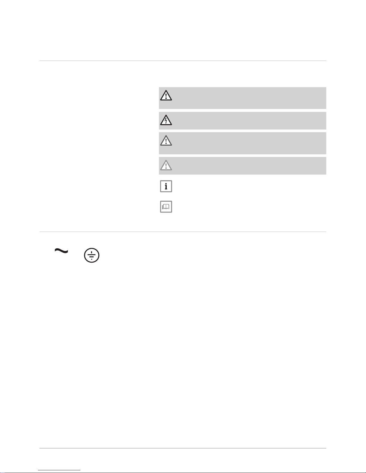
Danger
Risk of dangerous situations that may result in serious personal
injury.
Danger of electric shock
Risk of electric shock.
Warning
Risk of dangerous situations that may result in minor personal
injury.
Caution
Risk of material damage.
Important
Please note: important information.
See
Reference to other manuals or pages in this manual.
2.2 Symbols used on the appliance
1 Alternating current
2 Protective earthing
Fig.1 Symbols used on the appliance
MW-6000066-3
1 2
2 Symbols used
10 MIV-4S V200 7682822 - v03 - 27082018
Page 11
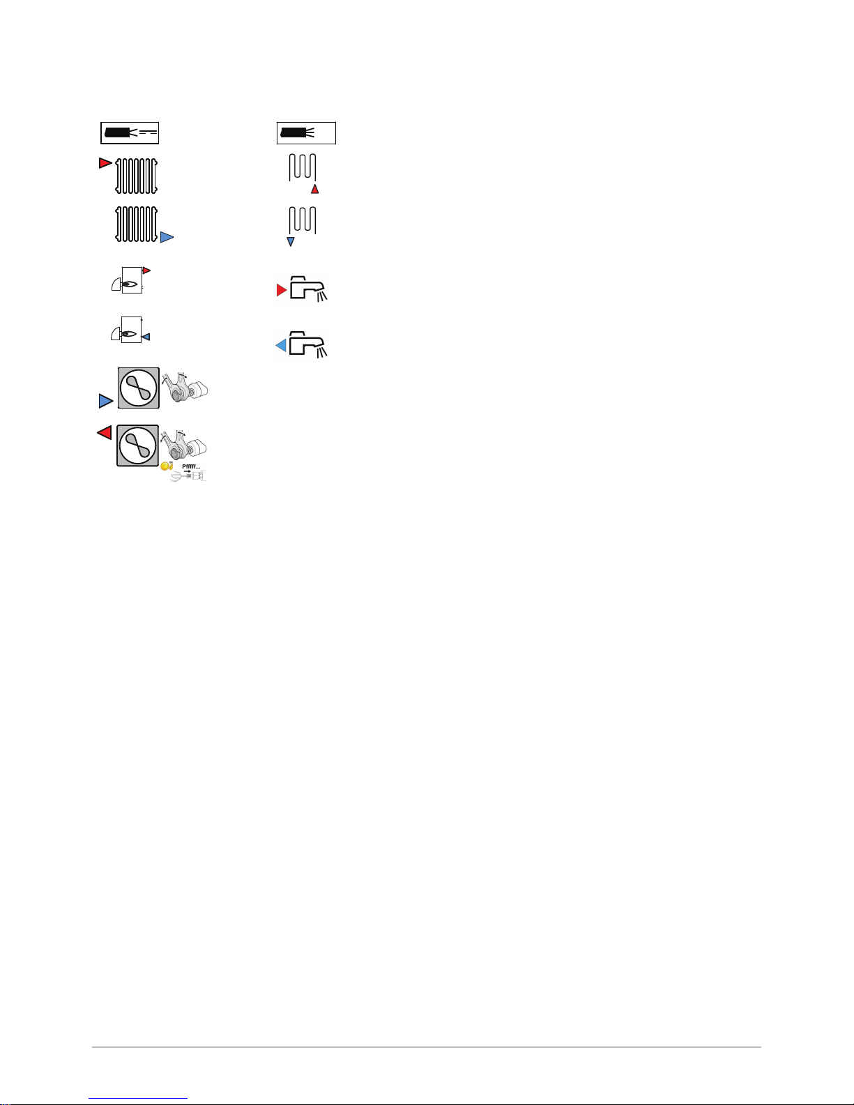
1 Sensor cable - low voltage
2 Power supply cable 230 V / 400 V
3 Heating circuit flow
4 Circuit B flow
5 Heating circuit return
6 Circuit B return (optional)
7 Return from boiler back-up
8 Domestic hot water outlet
9 Flow to boiler back-up
10 Domestic cold water inlet
11 3/8" refrigerant fluid connection – liquid line
12 5/8" refrigerant fluid connection – gas line
Fig.2 Symbols used on the connection
label
MW-3000554-02
A
G1"
A
G1"
G3/4"
G3/4"
5/8"
69-82 Nm
3/8"
34-42 Nm
1
2
4
6
8
3
5
7
9
11
12
B
G1"
B
G1"
G3/4"
G3/4"
10
2 Symbols used
7682822 - v03 - 27082018 MIV-4S V200 11
Page 12
3 Technical specifications
3.1 Homologations
3.1.1 Directives
This product complies with the requirements of the following European
Directives and Standards:
Pressure Equipment Directive 2014/68/EU
Low Voltage Directive 2014/35/EU
Generic standard: EN 60335-1
Relevant standards: EN 60335-2-21, EN 60335-2-40
Electromagnetic Compatibility Directive 2014/30/EU
Generic standards: EN 61000-6-3, EN 61000-6-1
Relevant Standard: EN 55014
This product conforms to the requirements of European Directive
2009/125/EC on the ecodesign of energy-related products.
In addition to the legal requirements and guidelines, the supplementary
guidelines in this manual must also be followed.
Supplements or subsequent regulations and guidelines that are valid at
the time of installation shall apply to all regulations and guidelines
specified in this manual.
3.1.2 Factory test
Before leaving the factory, each indoor module is tested on the following
items:
Tightness of the heating circuit
Electrical safety
Tightness of the refrigerant circuit
Tightness of the domestic hot water circuit
3.2 Technical data
3.2.1 Heat pump
The specifications are valid for a new appliance with clean heat
exchangers.
Maximum operating pressure: 0.3 MPa (3 bar)
Tab.1 Conditions of use
AWHP 4.5 MRAWHP 6
MR-3
AWHP 8
MR-2
AWHP 11
MR-2
AWHP 11
TR-2
AWHP 16
MR-2
AWHP 16
TR-2
Limit water operating
temperatures in heating
mode
+18 °C /
+55 °C
+18 °C /
+60 °C
+18 °C /
+60 °C
+18 °C /
+60 °C
+18 °C /
+60 °C
+18 °C /
+60 °C
+18 °C /
+60 °C
Outdoor air operating
temperature limits in
heating mode
-15 °C /
+35 °C
-15 °C /
+35 °C
-20 °C /
+35 °C
-20 °C /
+35 °C
-20 °C /
+35 °C
-20 °C /
+35 °C
-20 °C /
+35 °C
Water operating temper
ature limits in cooling
mode
+7 °C /
+25 °C
+7 °C /
+25 °C
+7 °C /
+25 °C
+7 °C /
+25 °C
+7 °C /
+25 °C
+7 °C /
+25 °C
+7 °C /
+25 °C
Outdoor air operating
temperature limits in
cooling mode
+7 °C /
+46 °C
+7 °C /
+46 °C
+7 °C /
+46 °C
+7 °C /
+46 °C
+7 °C /
+46 °C
+7 °C /
+46 °C
+7 °C /
+46 °C
3 Technical specifications
12 MIV-4S V200 7682822 - v03 - 27082018
Page 13

Tab.2 Heating mode: outside air temperature +7 °C, water temperature at the outlet +35 °C. Performances in accordance
with EN 14511-2.
Measurement type Unit AWHP 4.5 MRAWHP 6
MR-3
AWHP 8
MR-2
AWHP 11
MR-2
AWHP 11
TR-2
AWHP 16
MR-2
AWHP 16
TR-2
Heat output kW 4.60 5.82 7.9 11.39 11.39 14.65 14.65
Coefficient of Perform
ance (COP)
5.11 4.22 4.34 4.65 4.65 4.22 4.22
Absorbed electrical powerkWe 0.90 1.38 1.82 2.45 2.45 3.47 3.47
Nominal water flow rate
(ΔT = 5K)
m3/h
0.80 1.00 1.36 1.96 1.96 2.53 2.53
Tab.3 Heating mode: outside air temperature +2 °C, water temperature at the outlet +35 °C. Performances in accordance
with EN 14511-2.
Measurement type Unit AWHP 4.5 MRAWHP 6
MR-3
AWHP 8
MR-2
AWHP 11
MR-2
AWHP 11
TR-2
AWHP 16
MR-2
AWHP 16
TR-2
Heat output kW 3.47 3.74 6.80 10.19 10.19 12.90 12.90
Coefficient of Perform
ance (COP)
3.97 3.37 3.30 3.20 3.20 3.27 3.27
Absorbed electrical powerkWe 0.88 1.11 2.06 3.19 3.19 3.94 3.94
Tab.4 Cooling mode: outside air temperature +35 °C, water temperature at the outlet +18 °C. Performances in accordance
with EN 14511-2.
Measurement type Unit AWHP 4.5 MRAWHP 6
MR-3
AWHP 8
MR-2
AWHP 11
MR-2
AWHP 11
TR-2
AWHP 16
MR-2
AWHP 16
TR-2
Cooling output kW 3.80 4.69 7.90 11.16 11.16 14.46 14.46
Energy efficiency ratio
(EER)
4.28 4.09 3.99 4.75 4.75 3.96 3.96
Absorbed electrical powerkWe 0.89 1.15 2.00 2.35 2.35 3.65 3.65
Tab.5 Common specifications
Measurement type Unit AWHP 4.5 MRAWHP 6
MR-3
AWHP 8
MR-2
AWHP 11
MR-2
AWHP 11
TR-2
AWHP 16
MR-2
AWHP 16
TR-2
Total dynamic head at
nominal flow rate
kPa 65 63 44 25 25 — —
Nominal air flow rate
m3/h
2680 2700 3300 6000 6000 6000 6000
Power voltage of the out
door unit
V 230 230 230 230 400 230 400
Start-up amperage A 5 5 5 5 3 6 3
Maximal amperage A 12 13 17 29.5 13 29.5 13
Acoustic power - Inner
side
(1)
dB(A) 49 49 49 48 48 48 48
Acoustic power - Outside dB(A) 61 65 67 69 69 70 70
Refrigerant fluid R410A kg 1.3 1.4 3.2 4.6 4.6 4.6 4.6
R410A refrigerant
(2)
tCO2e 2.714 2.923 6.680 9.603 9.603 9.603 9.603
Refrigerant connection
(Liquid - Gas)
inch 1/4 - 1/2 1/4 - 1/2 3/8 - 5/8 3/8 - 5/8 3/8 - 5/8 3/8 - 5/8 3/8 - 5/8
Max. pre-charged length m 7 10 10 10 10 10 10
(1) Noise radiated by the enclosure - Test run in accordance with the NF EN 12102 standard, temperature conditions: air 7 °C, water 55 °C
(except for AWHP 4.5 MR: air 7 °C, water 45 °C inner and outer sides)
(2) The quantity of refrigerant in tonnes of CO2 equivalent is calculated using the following formula: quantity (in kg) of refrigerant x GWP/
1000. The Global-Warming Potential (GWP) of R410A gas is 2088.
3 Technical specifications
7682822 - v03 - 27082018 MIV-4S V200 13
Page 14

3.2.2 Heat pump weight
Tab.6 Indoor module
Indoor module Unit MIV-4S/E 4-8 V200 MIV-4S/H 4-8 V200 MIV-4S/E 11-16
V200
MIV-4S/H 11-16 V200
Weight (empty) kg 138 137 140 139
Total weight with
water
kg 333 332 335 334
Tab.7 Outdoor unit
Outdoor unit Unit AWHP 4.5 MR AWHP 6 MR-3 AWHP 8 MR-2 AWHP 11 MR-2
AWHP 16 MR-2
AWHP 11 TR-2
AWHP 16 TR-2
Weight (empty) kg 54 42 75 118 130
3.2.3 Domestic hot water tank
Tab.8 Technical specifications primary circuit (heating water)
Specification Unit Value
Maximum operating temperature
Version with hydraulic back-up
°C 90
Maximum operating temperature
Version with electrical back-up
°C 75
Minimum operating temperature °C 7
Maximum operating pressure MPa (bar) 0.3 (3.0)
Domestic hot water tank exchanger capacity Litres 11.3
Exchange surface m² 1.7
Tab.9 Technical specifications secondary circuit (domestic water)
Specification Unit Value
Maximum operating temperature °C 80
Minimum operating temperature °C 10
Maximum operating pressure MPa (bar) 1.0 (10.0)
Water capacity Litres 177
Tab.10 Common specifications (in accordance with the EN 16147 standard). Water set point temperature: 53 °C (except for
AWHP 4.5 MR: 54 °C) – Outdoor temperature: 7°C – Inside air temperature: 20°C
AWHP 4.5 MR
(cycle M)
AWHP 6 MR-3
(cycle L)
AWHP 8 MR-2
(cycle L)
AWHP 11 MR-2
AWHP 11 TR-2
(cycle L)
AWHP 16 MR-2
AWHP 16 TR-2
(cycle L)
Charging time 1 hour 40 minutes 2 hours 1 hour 58 minutes 1 hour 33 minutes 1 hour 11 minutes
Coefficient of performance
domestic hot water
(COP
DHW
)
2.50 2.72 2.72 2.72 2.72
3 Technical specifications
14 MIV-4S V200 7682822 - v03 - 27082018
Page 15

3.2.4 Combination heaters with medium-temperature heat
pump
Tab.11 Technical parameters for heat pump combination heaters (parameters declared for medium-temperature application)
Product name MIV-4S V200
AWHP 4.5 MR
MIV-4S V200
AWHP 6 MR-3
MIV-4S V200
AWHP 8 MR-2
Air-to-water heat pump Yes Yes Yes
Water-to-water heat pump No No No
Brine-to-water heat pump No No No
Low-temperature heat pump No No No
Equipped with a supplementary heater Yes Yes Yes
Heat pump combination heater Yes Yes Yes
Rated heat output under average conditions
(1)
Prated
kW 4 4 6
Rated heat output under colder conditions
Prated
kW 5 4 6
Rated heat output under warmer conditions
Prated
kW 4 5 6
Declared capacity for heating for part load at an in
door temperature of 20°C and outdoor temperature
T
j
T
j
= -7°C
Pdh
kW 3.8 3.5 5.6
T
j
= +2°C
Pdh
kW 4.3 4.5 2.9
T
j
= +7°C
Pdh
kW 4.5 4.8 6.4
T
j
= +12°C
Pdh
kW 5.5 5.2 4.3
T
j
= bivalent temperature
Pdh
kW 3.9 3.6 5.2
T
j
= operation limit temperature
Pdh
kW 3.9 3.6 5.2
Bivalent temperature
T
biv
°C -10 -10 -10
Degradation coefficient
(2)
Cdh
— 1.0 1.0 1.0
Seasonal space heating energy efficiency under
average conditions
ƞ
s
% 134 137 129
Seasonal space heating energy efficiency under
colder conditions
ƞ
s
% 109 116 119
Seasonal space heating energy efficiency under
warmer conditions
ƞ
s
% 179 172 169
Declared coefficient of performance or primary en
ergy ratio for part load at an indoor temperature of
20°C and outdoor temperature
T
j
T
j
= -7°C
COPd
- 1.64 1.89 1.95
T
j
= +2°C
COPd
- 3.46 3.53 3.22
T
j
= +7°C
COPd
- 4.96 4.74 4.57
T
j
= +12°C
COPd
- 7.90 7.08 6.55
T
j
= bivalent temperature
COPd
- 1.20 1.52 1.70
T
j
= operation limit temperature
COPd
- 1.20 1.52 1.70
Operation limit temperature for air-to-water heat
pumps
TOL
°C -10 -10 -10
Heating water operating limit temperature
WTOL
°C 55 60 60
Electrical power consumption
Off mode
P
OFF
kW 0.009 0.009 0.009
Thermostat-off mode
P
TO
kW 0.049 0.049 0.049
Stand-by
P
SB
kW 0.009 0.015 0.014
Crankcase heater mode
P
CK
kW 0.000 0.055 0.055
Supplementary heater
Rated heat output
Psup
kW 0.0 0.0 0.0
Type of energy input Electricity Electricity Electricity
Other specifications
3 Technical specifications
7682822 - v03 - 27082018 MIV-4S V200 15
Page 16

Product name MIV-4S V200
AWHP 4.5 MR
MIV-4S V200
AWHP 6 MR-3
MIV-4S V200
AWHP 8 MR-2
Capacity control Variable Variable Variable
Sound power level, indoors - outdoors
L
WA
dB 49 – 61 49 – 62 49 – 67
Annual energy consumption under average con
ditions
Q
HE
kWh 2353 2124 3499
Annual energy consumption under colder condi
tions
Q
HE
kWh 4483 3721 4621
Annual energy consumption under warmer condi
tions
Q
HE
kWh 1249 1492 1904
Rated air flow rate, outdoors for air-to-water heat
pumps
—
m3/h
2100 2100 3300
Declared load profile L L L
Daily electricity consumption
Q
elec
kWh 4,020 4,816 4,816
Annual electricity consumption
AEC
kWh 845 968 968
Water heating energy efficiency
ƞ
wh
% 121,00 106,00 106,00
Daily fuel consumption
Q
fuel
kWh 0.000 0.000 0.000
Annual fuel consumption
AFC
GJ 0 0 0
(1) The rated heat output
Prated
is equal to the design load for heating
Pdesignh
, and the rated heat output of a supplementary heater
Psup
is
equal to the supplementary capacity for heating
sup(Tj)
.
(2) If
Cdh
is not determined by measurement, the default degradation coefficient is
Cdh
= 0.9.
Tab.12 Technical parameters for heat pump combination heaters (parameters declared for medium-temperature application)
Product name MIV-4S V200
AWHP 11 MR-2
AWHP 11 TR-2
MIV-4S V200
AWHP 16 MR-2
AWHP 16 TR-2
Air-to-water heat pump Yes Yes
Water-to-water heat pump No No
Brine-to-water heat pump No No
Low-temperature heat pump No No
Equipped with a supplementary heater Yes Yes
Heat pump combination heater Yes Yes
Rated heat output under average conditions
(1)
Prated
kW 6 9
Rated heat output under colder conditions
Prated
kW 4 7
Rated heat output under warmer conditions
Prated
kW 8 13
Declared capacity for heating for part load at an in
door temperature of 20°C and outdoor temperature
T
j
T
j
= -7°C
Pdh
kW 5.9 9.0
T
j
= +2°C
Pdh
kW 5.3 6.5
T
j
= +7°C
Pdh
kW 9.0 12.9
T
j
= +12°C
Pdh
kW 7.7 10.0
T
j
= bivalent temperature
Pdh
kW 6.3 8.8
T
j
= operation limit temperature
Pdh
kW 6.3 8.8
Bivalent temperature
T
biv
°C -10 -10
Degradation coefficient
(2)
Cdh
— 1.0 1.0
Seasonal space heating energy efficiency under
average conditions
ƞ
s
% 125 121
Seasonal space heating energy efficiency under
colder conditions
ƞ
s
% 113 113
Seasonal space heating energy efficiency under
warmer conditions
ƞ
s
% 167 161
Declared coefficient of performance or primary en
ergy ratio for part load at an indoor temperature of
20°C and outdoor temperature
T
j
3 Technical specifications
16 MIV-4S V200 7682822 - v03 - 27082018
Page 17

Product name MIV-4S V200
AWHP 11 MR-2
AWHP 11 TR-2
MIV-4S V200
AWHP 16 MR-2
AWHP 16 TR-2
T
j
= -7°C
COPd
- 1.87 1.85
T
j
= +2°C
COPd
- 3.17 3.02
T
j
= +7°C
COPd
- 4.54 4.34
T
j
= +12°C
COPd
- 6.19 5.75
T
j
= bivalent temperature
COPd
- 1.20 1.35
T
j
= operation limit temperature
COPd
- 1.20 1.35
Operation limit temperature for air-to-water heat
pumps
TOL
°C -10 -10
Heating water operating limit temperature
WTOL
°C 60 60
Electrical power consumption
Off mode
P
OFF
kW 0.009 0.009
Thermostat-off mode
P
TO
kW 0.023 0.035
Stand-by
P
SB
kW 0.023 0.023
Crankcase heater mode
P
CK
kW 0.055 0.055
Supplementary heater
Rated heat output
Psup
kW 0.0 0.0
Type of energy input Electricity Electricity
Other specifications
Capacity control Variable Variable
Sound power level, indoors - outdoors
L
WA
dB 48 – 69 48 – 70
Annual energy consumption under average con
ditions
Q
HE
kWh 3999 5861
Annual energy consumption under colder condi
tions
Q
HE
kWh 3804 5684
Annual energy consumption under warmer condi
tions
Q
HE
kWh 2580 4120
Rated air flow rate, outdoors for air-to-water heat
pumps
—
m3/h
6000 6000
Declared load profile L L
Daily electricity consumption
Q
elec
kWh 4,816 4,816
Annual electricity consumption
AEC
kWh 968 968
Water heating energy efficiency
ƞ
wh
% 106,00 106,00
Daily fuel consumption
Q
fuel
kWh 0.000 0.000
Annual fuel consumption
AFC
GJ 0 0
(1) The rated heat output
Prated
is equal to the design load for heating
Pdesignh
, and the rated heat output of a supplemen
tary heater
Psup
is equal to the supplementary capacity for heating
sup(Tj)
.
(2) If
Cdh
is not determined by measurement, the default degradation coefficient is
Cdh
= 0.9.
See
The back cover for contact details.
3.2.5 Circulating pump
Important
The benchmark for the most efficient circulating pumps is EEI ≤
0.20.
3 Technical specifications
7682822 - v03 - 27082018 MIV-4S V200 17
Page 18

4 Description of the product
4.1 Main components
1
Control panel access flap
2
User interface
3
ON/OFF button
4.2 Operating principle
The outdoor unit produces heat or cold and transfers it to the indoor
module via the refrigerant in the plate exchanger.
The indoor module is equipped with a specific control system which is
used to adjust the temperature of the heating water to the needs of the
home.
Fig.3
Main components
MW-3000471-2
1
3
2
4 Description of the product
18 MIV-4S V200 7682822 - v03 - 27082018
Page 19

5 Operation
5.1 Control panel description
5.1.1 Description of the user interface
1 Rotary knob to select a menu or setting
2
Validation button
3
Back key to return to the previous level or previous menu
4
Main menu key
5 Display screen
6 LED for status indication:
continuous green = normal operation
flashing green = warning
continuous red = shutdown
flashing red = lockout
5.1.2 Description of the home screen
This screen is displayed automatically after the appliance is started up.
The screen goes into standby if no key is pressed for five minutes. Press
one of the buttons on the user interface to exit standby.
1 Access icons for menus and parameters
The selected icon is highlighted.
2 Information on the selected icon
3
error notification: only visible if an error occurs
4 Navigation level:
: User level
: Installer level.
This level is reserved for installers and is protected by an access
code. When this level is active, the
Off
icon becomes On.
Tab.13 Icons on the home screen and information
Icon Information Description of the icon
( i ) Error status Information on operation of the appliance
Maintenance status Maintenance message
Installer access Installer Level
Holiday programme Holiday mode for all circuits simultaneously
23.5
Air source heat pump Heat pump flow temperature display
Water pressure Current water pressure display
, , , ,
, ,
CIRCA/CIRCB
Symbol representing the operation zone
Room temperature display for zone A/B/C
DHW tank Temperature display for the domestic hot water
Outdoor temperature Outdoor temperature display
Fig.4
MW-5000756-1
3
4
1
2
5
6
Fig.5
29,6°C
51,2°C 6,7°C
29,4°C1,8 bar
Not Set
None OFF
OK
I
I
MW-3001011-1
23,2°C
2 431
5 Operation
7682822 - v03 - 27082018 MIV-4S V200 19
Page 20

5.2 Starting and stopping the heat pump
5.2.1 Starting the heat pump
1. Switch on the outdoor unit and the indoor module.
The message "Welcome" will appear on the screen. The heat pump
begins its start-up cycle.
2. If an error message is displayed on the home screen, contact the
installer.
5.2.2
Shutting down the heat pump
The heat pump must be shut down in certain situations, for example
during any intervention on the equipment. In other situations, such as an
extended absence period, we recommend that the Holiday operating
mode is used in order to benefit from the heat pump anti-blocking function
and to protect the installation from frost.
To shut down the heat pump:
1. Switch off the outdoor unit and the indoor module.
5.3
Switching the central heating on/off
The heating function can be switched off for all circuits. This can lead to
energy savings, for example, during the summer period.
Important
If the heating function is shut off, then the cooling will also be shut
off.
1. Select the
23.5
Air Src Heat pump icon.
2. Select CH function on.
3. Select the desired value:
Off to stop the heating function.
On to switch the heating function on again.
5.4 Periods of absence or going on holiday
If you will be absent for several weeks, you can reduce the room
temperature and domestic hot water temperature in order to save energy.
To do this, activate the Holiday operating mode for all zones, including for
domestic hot water.
1. Select the Holiday Mode icon.
2. Set the following parameters:
Tab.14
Parameter Description
Start date holiday Set the date and time for the start of the absence period.
End date holiday Set the date and time for the end of the absence period.
RoomT. Holiday Set the desired room temperature for the absence period
Reset Restart or cancel the holiday programme
5.5
Regional and ergonomic parameters
You can personalise your appliance by modifying the parameters linked to
your geographic location and the ergonomics of the control panel.
1. Press the key.
2. Select System Settings.
Off
5 Operation
20 MIV-4S V200 7682822 - v03 - 27082018
Page 21

3. Carry out one of the following operations:
Tab.15
Menu Description
Set Date and Time Setting the date and time
Select Country and Language Select the country and language.
Daylight Saving Time
Setting the automatic change to daylight saving time. These changes will be carried out on the
last Sunday in March and October
Installer Details Display the installer details
Set Heating Activity Names Modify the name of activities used to program heating periods
Set Cooling Activity Names Modify the name of activities used to program cooling periods
Set Screen Brightness Setting the screen brightness
Set click sound Switch the sound of the rotary knob on or off
Firmware Update Display the software version
License Information Display the creation licenses for the internal software
5.6
Personalising the zones
5.6.1 Definition of the term "zone"
Term given to the different hydraulic circuits (CIRCA, CIRCB). It indicates
several rooms served by the same circuit.
Tab.16 Example:
Key Zone Factory-set name
1
Zone 1 CIRCA
2
Zone 2 CIRCB
5.6.2 Changing the name and symbol of a zone
The name and symbol for a zone are factory-set as shown in the
appendix. If you desire, you can personalise the name and symbol of the
zones in your installation.
1. Select the icon for the zone to be modified, , for example.
2. Select Zone configuration > Zone friendly Name.
3. Modify the name of the zone (20 characters max.).
4. Select Icon display zone
5. Select the symbol to be associated with the zone.
6. Enter the chosen name and symbol in the table provided at the back
of the manual.
5.7
Personalising the activities
5.7.1 Activity
This term is used when programming time ranges. It refers to the client's
desired comfort level for different activities during the course of the day.
One set point temperature is associated to each activity. The last activity
of the day remains valid until the first activity of the following day.
Fig.6
1
MW-1001145-2
2
Off
5 Operation
7682822 - v03 - 27082018 MIV-4S V200 21
Page 22

Tab.17 Example:
Start
of the activity
Activity Set point temperature
6:30
Morning
1
20 °C
9:00
Away
2
19 °C
17:00
Home
3
20 °C
20:00
Evening
4
22 °C
23:00
Sleep
5
16 °C
5.7.2 Changing the name of an activity
The name of the different activities is factory-set: Sleep, Home, Away,
Morning, Evening and Custom. If you desire, you can personalise the
name of the activities for all of the zones in your installation.
1. Press the key.
2. Select System Settings.
3. Select Set Heating Activity Names or Set Cooling Activity Names.
4. Select the activity you want to change.
5. Change the name of the activity (10 characters max.).
6. Enter the chosen name in the table provided at the back of the
manual.
5.7.3 Changing the temperature of an activity
The temperatures for the different activities are factory-set as shown in the
appendix. If you desire, you can personalise the temperatures for these
activities for all of the zones in your installation. These activities are used
in the timer programmes.
1. Select the icon for the zone to be programmed, , for example.
2. Select Set Heating Activity Temperatures, either for heating or for
cooling.
Information on the selected menu is given in the lower part of the
screen.
3. Select the activity you want to change.
4. Modify the temperature for the activity.
5. Enter the chosen temperature in the table provided at the back of the
manual.
5.8
Room temperature for a zone
5.8.1 Selecting the operating mode
To set the room temperature for the different living zones, you can choose
between five operating modes. We recommend the Scheduling operating
mode which enables the room temperature to be modulated according to
your needs and to optimise your energy consumption.
1. Select the icon for the affected zone, , for example.
Fig.7
MW-1001144-2
°C
16
06:30 09:00 17:00 20:00 23:00
19
20
22
5
1
2
3
4
5
Off
Off
Off
5 Operation
22 MIV-4S V200 7682822 - v03 - 27082018
Page 23

2. Select the desired operating mode:
Tab.18
Mode Description
Scheduling
The room temperature is modulated according to the timer programme chosen.
Recommended mode.
Manual
The room temperature is constant.
Short temperature change
The room temperature is forced for a defined period.
Holiday
The room temperature is reduced during an absence period to save energy.
Antifrost
The installation and equipment are protected against frost during the winter peri
od.
5.8.2 Activating and configuring a timer programme for heating
A timer programme can be used to vary the room temperature in a living
zone depending on activities during the day. This can be programmed for
each day of the week.
1. Select the icon for the zone to be programmed, , for example.
Information on the current operating mode is given in the upper part
of the screen.
2. To activate the timer programming or to change the timer programme,
select Scheduling.
3. Select the timer programme to be activated.
Information on the active timer programme is given in the upper part
of the screen.
4. To modify the timer programme, select Zone configuration > Heating
Schedule.
5. Select the programme to be modified.
The programmed activities for Sunday are displayed.
The last activity of the day remains active until the first activity of the
following day.
6. Select the day to be modified.
7. Carry out the following actions according to your needs:
Modify the timings for programmed activities.
Add a new time range.
Delete a programmed activity (choose the activity "Delete").
Copy programmed daily activities to other days.
Modify temperatures linked to an activity.
5.8.3 Activating and configuring a timer programme for cooling
You can modify the timer programme linked to the Cooling mode. In the
Scheduling operating mode, the Cooling timer programme is activated
automatically when the average outdoor temperature over a 24-hour
period has been greater than 22 °C. If you would prefer that this mode is
triggered at a different temperature, ask your installer to modify this
parameter in your installation.
1. Select the icon for the zone to be programmed, , for example.
Information on the current operating mode is given in the upper part
of the screen.
Off
Fig.8
Heating Schedule
Zone setup Z...
14 : 23
Sunday
6:00 House
20.0°C
Edit schedule entry
6:00
House 20.0°C
22.00
Nuit
16.00°C
Add time and Activity
Copy to other day
Set activity temperatures
MW-5000770-2
Off
5 Operation
7682822 - v03 - 27082018 MIV-4S V200 23
Page 24

2. To modify the timer programme for the Cooling mode, select Zone
configuration > Cooling Schedule.
The programmed activities for Sunday are displayed.
The last activity of the day remains active until the first activity of the
following day.
3. Select the day to be modified.
4. Carry out the following actions according to your needs:
Modify the timings for programmed activities.
Add a new activity.
Delete a programmed activity (choose the activity "Delete").
Copy programmed daily activities to other days.
Modify temperatures linked to an activity.
5.8.4 Changing the room temperature temporarily
Regardless of the operating mode selected for a zone, it is possible to
modify the room temperature for a defined period. Once this time has
elapsed, the selected operating mode will restart.
1. Select the icon for the zone to be modified; , for example.
2. Select Short temperature change.
3. Define the duration in Hour and in Minute.
4. Set the temporary room temperature set point for the circuit selected.
5.9
Domestic hot water temperature
5.9.1 Selecting the operating mode
For the production of domestic hot water, you can choose between five
operating modes. We recommend the Scheduling mode which enables
domestic hot water production periods to be programmed according to
your needs and to optimise your energy consumption.
1. Select the DHW tank icon.
2. Select the desired operating mode:
Tab.19
Mode Description
Scheduling
The domestic hot water is produced according to the timer programme
chosen
Manual
The domestic hot water temperature remains at the comfort temperature
permanently
Hot water boost
The production of domestic hot water is forced at the comfort temperature
for a defined duration
Holiday
The domestic hot water temperature is reduced during an absence period
to save energy
Antifrost
The installation and equipment are protected during the winter period
5.9.2 Activating and configuring a timer programme for
domestic hot water
A timer programme can be used to vary the domestic hot water
temperature depending on activities during the day. This can be
programmed for each day of the week.
1. Select the DHW tank icon.
Information on the current operating mode is given in the upper part
of the screen.
2. To activate the timer programming or to change the timer programme,
select Scheduling.
Fig.9
Cooling Schedule
Zone setup: ... Zo..
14 : 23
Sunday
14:00 Comfort
24.0°C
Edit schedule entry
14:00
Comfort 24.0°C
Add time and Activity
Copy to other day
Set activity temperatures
MW-1001267-2
Off
Off
Off
5 Operation
24 MIV-4S V200 7682822 - v03 - 27082018
Page 25

3. Select the timer programme to be activated.
Information on the active timer programme is given in the upper part
of the screen.
4. To modify the timer programme, select Zone configuration > DHW
Schedule.
5. Select the programme to be modified.
The programmed activities for Sunday are displayed.
The last activity of the day remains active until the first activity of the
following day.
6. Select the day to be modified.
7. Carry out the following actions according to your needs:
Modify the timings for programmed activities.
Add a new activity.
Delete a programmed activity (choose the activity "Delete").
Copy programmed daily activities to other days.
Modify temperatures linked to an activity.
5.9.3 Forcing domestic hot water production (override)
Regardless of the selected operating mode, you can force domestic hot
water protection to the comfort temperature (DHW comfort setpoint
parameter) for a defined duration.
1. Select the DHW tank icon.
2. Select Hot water boost.
3. Define the duration in Hour and in Minute.
5.9.4 Modifying the domestic hot water set point temperatures
The production of domestic hot water operates with two set point
temperature parameters:
DHW comfort setpoint: used in the Scheduling, Manual and Hot water
boostmodes
DHW reduced setpoint: used in the Scheduling, Holiday and
Antifrostmodes
You can change these set point temperature settings to adapt them to
your needs.
1. Select the DHW tank icon.
2. Select DHW comfort setpoint to modify this set point.
3. Select Zone configuration > Domestic Hot Water Setpoints > DHW
reduced setpoint to modify this set point.
5.10
Monitoring the energy consumption
If your installation is equipped with an energy meter, you can monitor your
energy consumption.
1. Select the
23.5
Air Src Heat pump icon.
The energy consumed since the last energy consumption meter
reset is displayed:
Tab.20
Parameter Description
Cool Energy Consumpt Energy consumed for cooling
DHW Energy Consumed Enegy consumed for domestic hot water
CH Energy Consumed Energy consumed for central heating
2. To reset the meters to zero, select Reset counters for the energy
consumption.
Fig.10
DHW1: DHW Schedule
Zone setup...Zo...
14 : 23
Sunday
6:00 Comfort
55.0°C
Edit schedule entry
6:00
Comfort 55.0°C
Add time and Activity
Copy to other day
Set activity temperatures
MW-2000750-2
Off
Off
5 Operation
7682822 - v03 - 27082018 MIV-4S V200 25
Page 26

6 Maintenance
6.1 General
Maintenance operations are important for the following reasons:
To guarantee optimum performance.
To extend the life of the equipment.
To provide an installation which offers the user optimum comfort over
time.
Caution
Only qualified professionals are authorised to carry out
maintenance work on the heat pump and the heating system.
Danger of electric shock
Before any work, switch off the mains electricity to the heat pump
and the hydraulic or electrical back-up if present.
Caution
Before working on the refrigeration circuit, switch off the appliance
and wait a few minutes. Certain items of equipment such as the
compressor and the pipes can reach temperatures in excess of
100°C and high pressures, which may cause serious injuries.
Caution
Do not drain the installation, except in cases of absolute
necessity. E.g.: several months' absence with the risk of
temperatures in the building falling below freezing.
6.2 Standard inspection and maintenance operations
An annual inspection with tightness check is obligatory. Schedule a
service by a qualified professional at a cold time of the year to check the
following points:
1. Operation of the installation.
2. Thermal output, by measuring the difference in temperature between
heating flow and return.
3. The setting for the safety thermostats.
6.3 Maintenance message
When a maintenance operation is required, your appliance will alert you in
two ways:
A maintenance message will appear on the screen.
The Maintenance Status icon on the home screen flashes.
6.4
Displaying the maintenance information
Your appliance gives you information on necessary maintenance and
servicing operations.
1. Select the Maintenance Status icon.
Off
6 Maintenance
26 MIV-4S V200 7682822 - v03 - 27082018
Page 27

2. Consult the information linked to the maintenance and servicing of
your appliance:
Information Description
Maintenance required Indicates the necessity of mainte
nance: yes/no
Current maintenance Type of maintenance to come
Service run hours Number of hours that the
appliance has been producing
energy since last service
Hours since service Number of hours since the
previous servicing of the
appliance
Starts since service Number of heat generator starts
since the previous servicing.
6.5
Check the hydraulic pressure
Regularly check the hydraulic pressure in the installation. It should be
between 1.5 and 2 bar.
1. Select the Water Pressure icon.
2. Check the pressure that is displayed in the right section of the main
screen.
3. If the pressure is less than 1.5 bar, contact the installer so that they
can top up the water.
6.6 Cleaning the casing
1. Clean the outside of the appliance using a damp cloth and a mild
detergent.
Off
6 Maintenance
7682822 - v03 - 27082018 MIV-4S V200 27
Page 28

7 Troubleshooting
7.1 Resolving operating errors
If your appliance malfunctions, the status LED flashes and/or changes
colour and a message containing an error code is displayed on the main
screen of the control panel. This error code is important for the correct and
rapid diagnosis of the type of malfunction and for any technical assistance
that may be needed.
If an error occurs:
1. Make a note of the code displayed on the screen.
2. Remedy the problem described by the error code or contact the
installer.
3. Switch the heat pump off and back on to check that the cause of the
error has been removed.
4. If the code is displayed again, contact the installer.
7.1.1
Types of error code
The control panel can display three types of error codes:
Type of code Code format Colour of the status LED
Colour of the error icon
Warning Axx.xx Green flashing Blue
Blockage Hxx.xx Continuous red Yellow
Lock out Exx.xx Red flashing Red
7.2 Fault finding
Problems Probable causes Corrections
The radiators are cold. The heating set point tem
perature is too low.
Increase the value of the room temperature set point or, if a room ther
mostat is connected, increase the temperature on it.
The heating mode is deac
tivated.
Activate the heating mode.
The radiator valves are
closed.
Open the valves on all radiators connected to the heating system.
The heat pump is not op
erating.
Check that the heat pump is switched on.
Check the fuses and switches on the electrical installation.
The water pressure is too
low (< 1 bar).
Top up the system with water.
There is no domestic
hot water.
The domestic hot water
set point temperature is
too low.
Increase the domestic hot water set point temperature.
The domestic hot water
mode is deactivated.
Activate the domestic hot water mode.
The appliance is in re
duced domestic hot water
mode
Check and modify the comfort and reduced time ranges for the domes
tic hot water.
Adapt the domestic hot water set point temperature.
The shower head is re
stricting the water flow.
Clean the shower head; replace it if necessary.
The heat pump is not op
erating.
Check that the heat pump is switched on.
Check the fuses and switches on the electrical installation.
The water pressure is too
low (< 1 bar).
Top up the installation with water.
Significant variations in
domestic hot water
temperature
Insufficient water supply Check the water pressure in the installation.
Open the valve.
The domestic hot water
hysteresis is too high
Contact the professional responsible for maintenance of the heat pump.
7 Troubleshooting
28 MIV-4S V200 7682822 - v03 - 27082018
Page 29

Problems Probable causes Corrections
The heat pump does
not work.
The heating set point tem
perature is too low.
Increase the value of the room temperature set point or, if a room ther
mostat is connected, increase the temperature on it.
The heat pump is not op
erating.
Check that the heat pump is switched on.
Check the fuses and switches on the electrical installation.
The water pressure is too
low (< 1 bar).
Top up the system with water.
An error code appears on
the display.
Correct the error if possible.
The heat pump runs
short-cycling in do
mestic hot water mode
The temperature set point
is too low
Increase the set point
The water pressure is
too low (< 1 bar).
Not enough water in the
installation.
Top up the system with water.
Water leak. Contact the professional responsible for maintenance of the heat pump.
Clicking in the central
heating pipes
The central heating pipe
clamps are too tight.
Slightly loosen the clamps.
There is air in the heating
pipes.
Vent any air in the domestic hot water tank, the pipes and the taps to
prevent the annoying noises likely to be produced during heating or
when drawing off water.
The water is circulating too
quickly in the central heat
ing system.
Contact the professional responsible for maintenance of the heat pump.
Significant water leak
underneath or in the
vicinity of the heat
pump.
The pipes on the heat
pump or the central heat
ing are damaged.
Contact the professional responsible for maintenance of the heat pump.
7 Troubleshooting
7682822 - v03 - 27082018 MIV-4S V200 29
Page 30

8 Decommissioning and disposal
8.1 Decommissioning procedure
To decommission the heat pump temporarily or permanently:
1. Contact the installer.
8.2
Disposal and recycling
Warning
Removal and disposal of the heat pump must be carried out by a
qualified professional in accordance with prevailing local and
national regulations.
Fig.11
MW-3000179-03
8 Decommissioning and disposal
30 MIV-4S V200 7682822 - v03 - 27082018
Page 31

9 Energy savings
Energy-saving advice:
Do not block ventilation outlets.
Do not cover the radiators. Do not hang curtains in front of the radiators.
Install reflective panels behind the radiators to prevent heat losses.
Insulate the pipes in rooms that are not heated (cellars and lofts).
Close the radiators in rooms not in use.
Do not run hot (or cold) water pointlessly.
Install an energy-saving shower head, which can save up to 40 %
energy.
Take showers rather than baths. A bath consumes twice as much water
and energy.
9 Energy savings
7682822 - v03 - 27082018 MIV-4S V200 31
Page 32

10 Product fiche and package fiche
10.1 Product fiche
Tab.21 Product data sheet for heat pump combination heaters
MIV-4S V200
AWHP 4.5
MR
MIV-4S V200
AWHP 6 MR-3
MIV-4S V200
AWHP 8 MR-2
Space heating - Temperature application Medium Medium Medium
Water heating - Declared load profile L L L
Seasonal space heating energy efficiency class under average
climate conditions
A++A++A
++
Water heating energy efficiency class under average climate
conditions
AAA
Rated heat output under average climate conditions
(Prated or
Psup)
kW 4 4 6
Space heating - Annual energy consumption under average cli
mate conditions
kWh
GJ
(1)
2353 2124 3499
Water heating - Annual energy consumption under average cli
mate conditions
kWh
GJ
845 968 968
Seasonal space heating energy efficiency under average cli
mate conditions
% 134 137 129
Water heating energy efficiency under average climate condi
tions
% 121,00 106,00 106,00
Sound power level LWA indoors
(2)
dB 49 48 48
Ability to off-peak hours functioning No No No
Rated heat output, under colder - warmer climate conditions kW 5 – 4 4 – 5 6 – 6
Space heating - Annual energy consumption, under colder warmer climate conditions
kWh
GJ
4483 – 1249 3721 – 1492 4621 – 1904
Water heating - Annual energy consumption, under colder warmer climate conditions
kWh
(3)
GJ
(4)
1432 – 664 1432 – 664 1432 – 664
Seasonal space heating energy efficiency, under colder - warm
er climate conditions
% 109 – 179 116 – 172 119 – 169
Water heating energy efficiency, under colder - warmer climate
conditions
% 72,00 –
154,00
72,00 – 154,00 72,00 –
154,00
Sound power level LWA outdoors dB 61 64 66
(1) For gas heat pumps only
(2) If applicable.
(3) Electricity
(4) Fuel
Tab.22 Product fiche for heat pump combination heaters
MIV-4S V200
AWHP 11 MR-2
AWHP 11 TR-2
MIV-4S V200
AWHP 16 MR-2
AWHP 16 TR-2
Space heating - Temperature application Medium Medium
Water heating - Declared load profile L L
Seasonal space heating energy efficiency class under average climate
conditions
A++A
+
Water heating energy efficiency class under average climate conditions
A
A
Rated heat output under average climate conditions
(Prated or Psup)
kW 6 9
Space heating - Annual energy consumption under average climate con
ditions
kWh
GJ
(1)
3999 5861
Water heating - Annual energy consumption under average climate con
ditions
kWh
GJ
968 968
10 Product fiche and package fiche
32 MIV-4S V200 7682822 - v03 - 27082018
Page 33

MIV-4S V200
AWHP 11 MR-2
AWHP 11 TR-2
MIV-4S V200
AWHP 16 MR-2
AWHP 16 TR-2
Seasonal space heating energy efficiency under average climate condi
tions
% 125 121
Water heating energy efficiency under average climate conditions % 106,00 106,00
Sound power level LWA indoors
(2)
dB 47 47
Ability to function during off-peak hours No No
Rated heat output, under colder - warmer climate conditions kW 4 – 8 7 – 13
Space heating - Annual energy consumption, under colder - warmer cli
mate conditions
kWh
GJ
3804 – 2580 5684 – 4120
Water heating - Annual energy consumption, under colder - warmer cli
mate conditions
kWh
(3)
GJ
(4)
1432 – 664 1432 – 664
Seasonal space heating energy efficiency, under colder - warmer climate
conditions
% 113 – 167 113 – 161
Water heating energy efficiency, under colder - warmer climate conditions % 72,00 – 154,00 72,00 – 154,00
Sound power level LWA outdoors dB 69 69
(1) For gas heat pumps only
(2) If applicable.
(3) Electricity
(4) Fuel
See
For specific precautions on assembly, installation and
maintenance: see the chapter on Safety Instructions.
10.2 Product fiche - Temperature Controls
Tab.23 Product fiche for the Temperature controls
DIEMATIC
Evolution
Class II
Contribution to space heating energy efficiency % 2
10.3 Package fiche
Important
‘Medium-temperature application’ means an application where the
heat pump space heater or heat pump combination heater
delivers its declared capacity for heating at an indoor heat
exchanger outlet temperature of 55 °C.
10 Product fiche and package fiche
7682822 - v03 - 27082018 MIV-4S V200 33
Page 34

Fig.12 Package fiche for medium-temperature heat pumps indicating the space heating energy efficiency of the package
AD-3000745-01
%
1
‘I’
2
%+
3
%( - ‘I’ ) x ‘II’ = ±
4
%(‘III’ x + ‘IV’ x ) x 0.45 x ( /100) x = +
(1)
A* = 0.95, A = 0.91,
B = 0.86, C = 0.83,
D - G = 0.81
<30%
G F E D C B A A
+
A
++
A
+++
5
%
%+ ‘VI’ =
5
%- ‘V’ =
5
from fi che of solar device
Solar contribution
The energy effi ciency of the package of products provided for in this fi che may not correspond to its actual energy effi ciency once installed
in a building, as this effi ciency is infl uenced by further factors such as heat loss in the distribution system and the dimensioning of the
products in relation to building size and characteristics.
Seasonal space heating energy effi ciency class of package under average climate
Seasonal space heating energy effi ciency of package under average climate
Tank rating
Collector effi ciency (in
%)
Tank volume (in m³) Collector size (in m²)
Seasonal space heating energy effi ciency (in %)
Supplementary boiler
Class I = 1%, Class II = 2%, Class III = 1.5%,
Class IV = 2%, Class V = 3%, Class VI = 4%,
Class VII = 3.5%, Class VIII = 5%
Temperature control
Seasonal space heating energy effi ciency of heat pump
(1) If tank rating is above A, use 0.95
from fi che of boiler
from fi che of temperature control
Colder: Warmer:
Seasonal space heating energy effi ciency under colder and warmer climate conditions
I The value of the seasonal space heating energy efficiency of the
preferential space heater, expressed in %.
II The factor for weighting the heat output of preferential and
supplementary heaters of a package as set out in the following
table.
III The value of the mathematical expression: 294/(11 · Prated),
whereby "Prated" is related to the preferential space heater.
IV The value of the mathematical expression 115/(11 · Prated),
whereby "Prated" is related to the preferential space heater.
V The value of the difference between the seasonal space heating
energy efficiencies under average and colder climate conditions,
expressed in %.
VI The value of the difference between the seasonal space heating
energy efficiencies under warmer and average climate conditions,
expressed in %.
10 Product fiche and package fiche
34 MIV-4S V200 7682822 - v03 - 27082018
Page 35

Tab.24 Weighting of medium temperature heat pumps
Prated / (Prated + Psup)
(1)(2)
II, package without hot water storage tank II, package with hot water storage tank
0 1.00 1.00
0.1 0.70 0.63
0.2 0.45 0.30
0.3 0.25 0.15
0.4 0.15 0.06
0.5 0.05 0.02
0.6 0.02 0
≥ 0.7 0 0
(1) The intermediate values are calculated by linear interpolation between the two adjacent values.
(2) Prated is related to the preferential space heater or combination heater.
Tab.25 Package efficiency (temperature regulator + heat pump)
AWHP 4.5 MR AWHP 6 MR-3 AWHP 8 MR-2 AWHP 11 MR-2
AWHP 11 TR-2
AWHP 16 MR-2
AWHP 16 TR-2
DIEMATIC Evolution % 136 139 131 127 123
10 Product fiche and package fiche
7682822 - v03 - 27082018 MIV-4S V200 35
Page 36

10.4 Package fiche - Combination heaters (boilers or heat pumps)
Fig.13 Package fiche for combination heaters (boilers or heat pumps) indicating the water heating energy efficiency of the
package
AD-3000747-01
%
1
‘I’
2
%(1.1 x ‘I’ - 10%) x ‘II’ - - ‘I’ = +
‘III’
<28%
XXL
XL
L
M
G F E D C B A A
+
A
++
A
+++
3
%
%+ 0.4 x =
23
%- 0.2 x =
23
The energy effi ciency of the package of products provided for in this fi che may not correspond to its actual energy effi ciency once installed
in a building, as this effi ciency is infl uenced by further factors such as heat loss in the distribution system and the dimensioning of the
products in relation to building size and characteristics.
Water heating energy effi ciency class of package under average climate
Water heating energy effi ciency of package under average climate
Auxiliary electricity
Solar contribution
Water heating energy effi ciency of combination heater
from fi che of solar device
Colder:
Warmer:
Water heating energy effi ciency under colder and warmer climate conditions
Declared load profi le:
I The value of the water heating energy efficiency of the combination
heater, expressed in %.
II The value of the mathematical expression (220 · Q
ref
)/Q
nonsol
,
where Q
ref
is taken from Regulation EU 811/2013, Annex VII Table
15 and Q
nonsol
from the product fiche of the solar device for the
declared load profile M, L, XL or XXL of the combination heater.
III The value of the mathematical expression (Q
aux
· 2,5)/(220 · Q
ref
),
expressed in %, where Q
aux
is taken from the product fiche of the
solar device and Q
ref
from Regulation EU 811/2013, Annex VII
Table 15 for the declared load profile M, L, XL or XXL.
10 Product fiche and package fiche
36 MIV-4S V200 7682822 - v03 - 27082018
Page 37

11 Appendix
11.1 Name and symbol of the zones
Tab.26
Factory-set name Factory-set sym
bol
Customer-set name and symbol
CIRCA
CIRCB
11.2
Name and temperature of the activities
Tab.27 Name and temperature of the activities for heating
Activities
Factory-set name Factory-set tempera
ture
Name and temperature defined by the customer
Activity 1: Sleep 16 °C
Activity 2: Home 20 °C
Activity 3: Away 6 °C
Activity 4: Morning 21 °C
Activity 5: Evening 22 °C
Activity 6: Custom 20 °C
Tab.28 Name and temperature of the activities for cooling
Activities
Factory-set name Factory-set tempera
ture
Name and temperature defined by the customer
Activity 1: Sleep 30 °C
Activity 2: Home 25 °C
Activity 3: Away 25 °C
Activity 4: Morning 25 °C
Activity 5: Evening 25 °C
Activity 6: Custom 25 °C
11 Appendix
7682822 - v03 - 27082018 MIV-4S V200 37
Page 38

11 Appendix
38 MIV-4S V200 7682822 - v03 - 27082018
Page 39

© Copyright
All technical and technological information contained in these technical instructions, as well as any drawings and technical
descriptions supplied, remain our property and shall not be multiplied without our prior consent in writing. Subject to alterations.
Page 40

DE DIETRICH
FRANCE
NEUBERG S.A.
LU
DE DIETRICH SERVICE
AT
DE DIETRICH
CN
www.dedietrich-thermique.fr
www.neuberg.lu
www.dedietrich-heating.com
www.dedietrich-heating.com
www.dedietrich-heiztechnik.com
SERVICE CONSOMMATEURS
0 825 120 520
0,15 €
/ min
03 88 80 27 00
03 88 80 27 99
+352 (0)2 401 401
0800 / 201608 freecall
+86 (0)106 581 4017
+86 (0)106 581 4018
+86 (0)106 581 7056
+86 (0)106 581 4019
contactBJ@dedietrich.com.cn
Direction de la Marque
57, rue de la Gare - F-67580 Mertzwiller
VAN MARCKE
BE
www.vanmarcke.be
+32 (0)56/23 75 11
Weggevoerdenlaan 5
B- 8500 KORTRIJK
39 rue Jacques Stas - B.P.12
L- 2549 LUXEMBOURG
Room 512, Tower A, Kelun Building
12A Guanghua Rd, Chaoyang District
C-100020 BEIJING
DE DIETRICH THERMIQUE
I
beria S.L.U
ES
www.dedietrich-calefaccion.es
+34 935 475 850
info@dedietrich-calefaccion.es
C/Salvador Espriu, 11
08908 L’HOSPITALET de LLOBREGAT
BDR THERMEA C
zech Republic s.r.o
CZ
DE DIETRICH
Technika Grzewcza sp. z o.o.
PL
www.dedietrich.cz
www.facebook.com/DeDietrichPL
www.dedietrich.pl
+420 271 001 627
dedietrich@bdrthermea.cz
+48 71 71 27 400
biuro@dedietrich.pl
MEIER TOBLER AG
CH
www.meiertobler.ch
+41 (0) 44 806 41 41
info@meiertobler.ch
Bahnstrasse 24 - CH - 8603 SCHWERZENBACH
Serviceline
+41 (0)8 00 846 846
MEIER TOBLER SA
CH
www.meiertobler.ch
+41 (0) 21 943 02 22
info@meiertobler.ch
Chemin de la Veyre-d'En-Haut B6,
CH -1806 St-Légier-La-Chiésaz
Jeseniova 2770/56 - 130 00 Praha 3
ul. Północna 15-19, 54-105 Wrocław
Serviceline
+41 (0)8 00 846 846
000 «БДP T Pyc»
RU
www.dedietrich.ru
8 800 333-17-18
info@dedietrich.ru
129164, Россия, г. Москва
Зубарев переулок, д. 15 /1
Бизнес-центр «Чайка Плаза»,офис 309
DUEDI S.r.
l
IT
www.duediclima.it
+39 0171 85717 0
+39 0171 687875
info@duediclima.it
Distributore Uffi ciale Esclusivo
De Dietrich-Thermique Italia Via Passatore, 12
12010 San Defendente di Cervasca CUNEO
801 080 881
Infocentrala
7682822 - v03 - 27082018
7682822-001-03
 Loading...