

DeDietrich AWHP 6 MR, AWHP 8 MR, AWHP 14 MR, AWHP 11 MR, AWHP 14 TR Installation And Service Manual
...Page 1
HPI
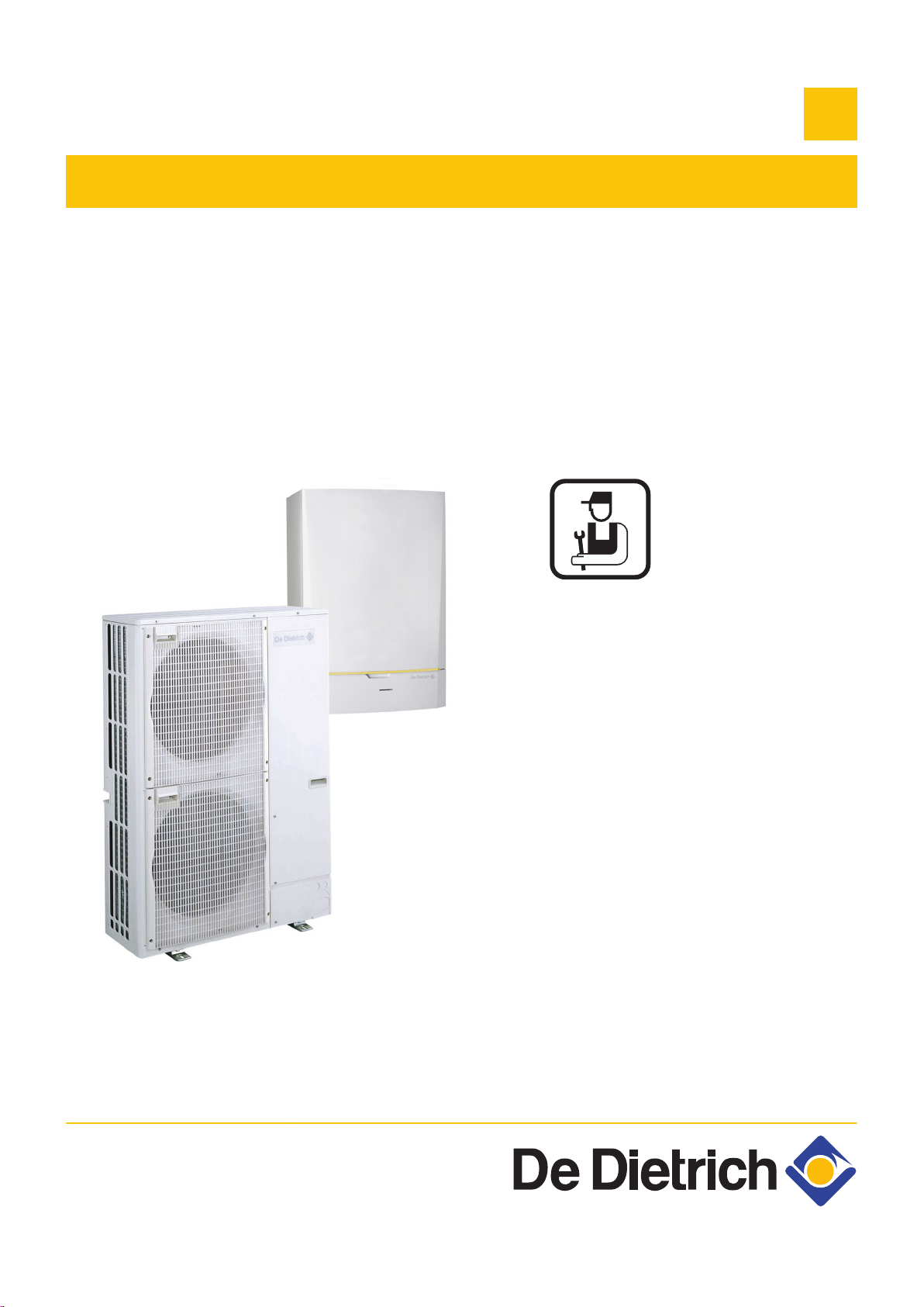
Air / water heat pump
AWHP MIT-IN iSystem
EN
Installation and
Service Manual
300027606-001-01
Page 2

Contents
1 Introduction ................................................................................................6
1.1 Symbols used .......................................................6
1.1.1 Symbols used in the manual ...................................6
1.1.2 Symbols used on the equipment .............................6
1.2 Abbreviations ........................................................7
1.3 General ..................................................................7
1.3.1 Manufacturer's liability .............................................7
1.3.2 Installer's liability .....................................................7
1.4 Homologations ......................................................8
1.4.1 Certifications ...........................................................8
2 Safety instructions and recommendations ..............................................9
2.1 Safety instructions ...............................................9
2.2 Recommendations ................................................9
3 Technical description ..............................................................................11
3.1 General description ............................................11
3.2 Main parts (Indoor module) ...............................11
3.2.1 MIT-IN/H ................................................................11
3.2.2 MIT-IN/E ................................................................12
3.3 Operating principle .............................................12
3.3.1 General .................................................................12
3.3.2 Skeleton Diagrams ................................................13
3.3.3 Pressure available .................................................14
3.4 Technical specifications ....................................14
3.4.1 Electricity supply ...................................................14
3.4.2 Heat pump .............................................................14
3.4.3 Sensor characteristics ...........................................15
4 Installation ................................................................................................17
4.1 Regulations governing installation ...................17
4.2 Package list .........................................................17
4.2.1 Standard delivery ..................................................17
4.2.2 Accessories ...........................................................18
1
24/09/2012 - 300027606-001-01
Page 3

Contents
4.3 Data plate .............................................................19
4.4 Installing the outdoor module ...........................19
4.4.1 Location of the appliance ......................................19
4.4.2 Main dimensions ...................................................22
4.4.3 Locating the outside module ................................26
4.5 Installing the indoor module ..............................27
4.5.1 Location of the appliance ......................................27
4.5.2 Main dimensions ...................................................27
4.5.3 Assembly of the MIT indoor module ......................28
4.6 Installing the outside sensor .............................29
4.6.1 Choice of the location ............................................29
4.6.2 Connecting the outside sensor ..............................29
4.7 Combination with a DHW tank ...........................30
4.8 Refrigeration connection ...................................30
4.8.1 Installing the pipes ................................................30
4.8.2 Water tightness test ..............................................35
4.8.3 Evacuation ............................................................35
4.8.4 Opening the valves ...............................................35
4.8.5 Adding refrigerant ..................................................36
4.9 Hydraulic connections .......................................36
4.9.1 Flushing the system ..............................................36
4.9.2 Connection of the heating circuit ...........................37
4.9.3 Hydraulic connection diagrams .............................37
4.10 Filling the heating system ..................................39
4.10.1 Water treatment in the heating circuit ...................39
4.10.2 Filling the system ..................................................40
4.11 Electrical connections ........................................41
4.11.1 Recommendations ................................................41
4.11.2 Recommended cable cross section ......................42
4.11.3 Accessing the connection terminal blocks ............43
4.11.4 Position of the PCBs .............................................44
4.11.5 Location of the fuse ...............................................45
4.11.6 Connecting the outdoor module ............................45
4.11.7 Connecting the communication cable between the
inside and outside modules ...................................45
4.11.8 Description of the terminal block on the inside
module ..................................................................46
4.11.9 Connecting the mains supply to the inside
module ..................................................................47
4.11.10 Connecting the electrical back-up to the inside
module (MIT-IN/E only) .........................................47
4.11.11 Connecting the hydraulic auxilary on the inside
module (MIT-IN/H only) .........................................49
4.11.12 Example of connecting a system with MIT-IN/
H ............................................................................50
4.11.13 Example of connecting a system with MIT-IN/
E ............................................................................54
4.11.14 Connection example in cooling mode ...................56
4.11.15 Pool connection .....................................................58
4.11.16 Connecting the options .........................................60
2
24/09/2012 - 300027606-001-01
Page 4

4.11.17 Connection in cascade ..........................................61
4.11.18 Connection example in power cut off EVU ............63
4.12 Electrical principle diagram ...............................66
5 Commissioning ........................................................................................70
5.1 Control panel .......................................................70
5.1.1 Description of the keys ..........................................70
5.1.2 Description of the display ......................................71
5.1.3 Access to the various browsing levels ..................74
5.1.4 Browsing in the menus ..........................................75
5.2 Check points before commissioning ................76
5.2.1 Hydraulic connections ...........................................76
5.2.2 Electrical connection .............................................76
5.3 Putting the appliance into operation ................77
5.4 Checks and adjustments after
commissioning ...................................................78
5.4.1 Displaying the parameters in extended
mode .....................................................................78
5.4.2 Setting the parameters specific to the
installation .............................................................78
5.4.3 Naming the circuits and generators ......................83
5.4.4 Setting the heating curve ......................................84
5.4.5 Setting the heating pump speed on the heat
pump .....................................................................86
5.4.6 Setting the speed of the heating pump on the inside
module ..................................................................86
5.4.7 Setting the flow rate threshold ...............................87
5.5 Reading out measured values ...........................88
5.6 Changing the settings ........................................89
5.6.1 Language selection ...............................................89
5.6.2 Calibrating the sensors .........................................90
5.6.3 Professional settings .............................................91
5.6.4 Configuring the network ........................................99
5.6.5 Return to the factory settings ..............................102
3
24/09/2012 - 300027606-001-01
Page 5

Contents
6 Switching off the appliance ...................................................................103
6.1 Installation shutdown .......................................103
6.2 Turning on the antifreeze function ..................103
7 Checking and maintenance ...................................................................104
7.1 General instructions .........................................104
7.2 Maintenance operations to be performed ......104
7.3 Cleaning the 400 µm filter ................................104
7.4 Customising maintenance ...............................105
7.4.1 Maintenance message ........................................105
7.4.2 Contact details of the professional for After Sales
Support ................................................................106
8 Troubleshooting .....................................................................................108
8.1 Anti-hunting ......................................................108
8.2 Messages ...........................................................108
8.3 Message history ................................................110
8.4 Faults (Code type Lxx or Dxx) .........................111
8.4.1 Deletion of sensors from the memory in the
PCB .....................................................................114
8.5 Failure history ...................................................115
8.6 Parameter and input/output check (mode
tests) ..................................................................115
9 Spare parts ..............................................................................................121
9.1 General ..............................................................121
9.2 Spare parts ........................................................121
9.2.1 AWHP 6 MR ........................................................121
9.2.2 AWHP 8 MR ........................................................123
9.2.3 AWHP 11 - 16 .....................................................126
9.2.4 AWHP 22 - 27 .....................................................132
9.2.5 MIT ......................................................................135
4
24/09/2012 - 300027606-001-01
Page 6

5
24/09/2012 - 300027606-001-01
Page 7
1 2
M002628-A
AWHP MIT-IN iSystem
1 Introduction
1.1 Symbols used
1. Introduction
1.1.1. Symbols used in the manual
In these instructions, various danger levels are employed to draw the
user's attention to particular information. In so doing, we wish to
safeguard the user's safety, obviate hazards and guarantee correct
operation of the appliance.
DANGER
Risk of a dangerous situation causing serious physical
injury.
WARNING
Risk of a dangerous situation causing slight physical
injury.
CAUTION
Risk of material damage.
Signals important information.
¼ Signals a referral to other instructions or other pages in the
instructions.
1.1.2. Symbols used on the equipment
4
~
Protective earthing
Alternating current
Before installing and commissioning the device, read
carefully the instruction manuals provided.
Dispose of the used products in an appropriate recovery
and recycling structure.
24/09/2012 - 300027606-001-01
Caution: danger, live parts.
Disconnect the mains power prior to any operations.
6
Page 8

1. Introduction
1.2 Abbreviations
AWHP MIT-IN iSystem
4 DHW: Domestic hot water
4 PPS: Polypropylene hardly inflammable
4 PCU: Primary Control Unit - PCB contoller for heat pump operation
4 PSU: Parameter Storage Unit - Parameter storage for PCBs
PCU and SU
4 SCU: Secondary Control Unit - DIEMATIC iSystem control panel
PCB
4 SU: Safety Unit - Safety PCB
4 3WV: 3-way valve
4 EVU: Power supply company
4 MIT: Indoor module fitted with a DIEMATIC iSystem control panel
4 HP: Heat pump
4 EER: Frigorific efficiency ratio
4 COP: Performance coefficient
1.3 General
1.3.1. Manufacturer's liability
Our products are manufactured in compliance with the requirements
of the various applicable European Directives. They are therefore
delivered with [ marking and all relevant documentation.
In the interest of customers, we are continuously endeavouring to
make improvements in product quality. All the specifications stated in
this document are therefore subject to change without notice.
Our liability as the manufacturer may not be invoked in the following
cases:
4 Failure to abide by the instructions on using the appliance.
4 Faulty or insufficient maintenance of the appliance.
4 Failure to abide by the instructions on installing the appliance.
1.3.2. Installer's liability
The installer is responsible for the installation and inital start up of the
appliance. The installer must respect the following instructions:
4 Read and follow the instructions given in the manuals provided
with the appliance.
4 Carry out installation in compliance with the prevailing legislation
and standards.
4 Perform the initial start up and carry out any checks necessary.
4 Explain the installation to the user.
7
24/09/2012 - 300027606-001-01
Page 9

AWHP MIT-IN iSystem 1. Introduction
4 If a maintenance is necessary, warn the user of the obligation to
check the appliance and maintain it in good working order.
4 Give all the instruction manuals to the user.
1.4 Homologations
1.4.1. Certifications
This product complies to the requirements to the european directives
and following standards:
4 2006/95/EC Low Voltage Directive. Reference Standards:
EN60335-1 / EN60335-2-40.
4 2004/108/EC Electromagnetic Compatibility Directive. Generic
standards: EN1000-6-3 , EN 61000-6-1.
24/09/2012 - 300027606-001-01
8
Page 10
2. Safety instructions and recommendations AWHP MIT-IN iSystem
2 Safety instructions and
recommendations
2.1 Safety instructions
DANGER
If smoke is released or in case of refrigerant leak:
1. Do not use a naked flame, do not smoke, do not
operate electrical contacts or switches ( doorbell,
light, motor, lift, etc..).
Contact between refrigerant and a flame may result
in emissions of toxic gases.
2. Open the windows.
3. Trace possible leaks and seal them immediately.
2.2 Recommendations
WARNING
Before any work, switch off the mains supply to the
appliance.
WARNING
Do not touch the refrigeration connection pipes with your
bare hands while the appliance is running. Danger of
burns or frost injury.
WARNING
4 Any intervention on the appliance and heating
equipment must be carried out by a qualified
engineer.
4 For a proper operating of the boiler, follow carefully
the instructions.
9
24/09/2012 - 300027606-001-01
Page 11
AWHP MIT-IN iSystem 2. Safety instructions and recommendations
Keep this document close to the place where the boiler is
installed.
CAUTION
4 Use tools and pipe components especially designed
for use with R410A refrigerant.
4 Install the appliance on a solid, stable structure able
to bear its weight.
4 Use phosphorous-deoxidised copper for pipes
without welds and copper alloy to connect the pipes
carrying the refrigerant.
4 Use only R410A gas to fill the pipes with refrigerant.
4 Do not install the appliance in a place where it may
be exposed to steam, sulphuric gas or combustion,
an atmosphere with a high salt content, or which may
be covered by snow.
4 Ensure correct earthing.
4 Store the refrigeration connection pipes away from
dust and humidity (danger of damage to the
compressor) and cover both ends until the expansion
process is complete.
4 Do not use a load cylinder.
CAUTION
4 Activate the main switch at least 12 hours before the
appliance starts to function. Using the appliance just
after it is switched on may seriously damage the
internal parts.
4 When switching off the appliance, wait for at least 5
minutes of post-operation before deactivating the
main switch. Danger of breakdown or water leak.
CAUTION
In order to limit the risk of being scalded, the installation of
a thermostatic mixing valve on the domestic hot water flow
piping is compulsory.
Before carrying out any maintenance work requiring the
shutdown of the inside module, also cut the power supply
to the outside module to prevent any errors in
communication.
24/09/2012 - 300027606-001-01
10
Page 12
M002483-A
2
3
5
4
8
7
6
11
10
9
1
3. Technical description AWHP MIT-IN iSystem
3 Technical description
3.1 General description
The AWHP MIT-IN iSystem heat pump is composed of two
elements:
4 The outside unit handles energy production in hot or cold mode.
4 The inside module handles thermal exchange between the R410A
fluid and the hydraulic circuit.
The two units are connected by means of refrigeration and electrical
connections.
The system offers the following advantages:
4 The heating circuit is housed in the insulated volume within the
home. There is no danger of the pipes freezing.
4 Thanks to the DC inverter system, the heat pump modulates its
output to adapt to the needs of the home.
4 The control panel uses the outside temperature sensor to adjust
the temperature of the heating circuit according to the outside
temperature.
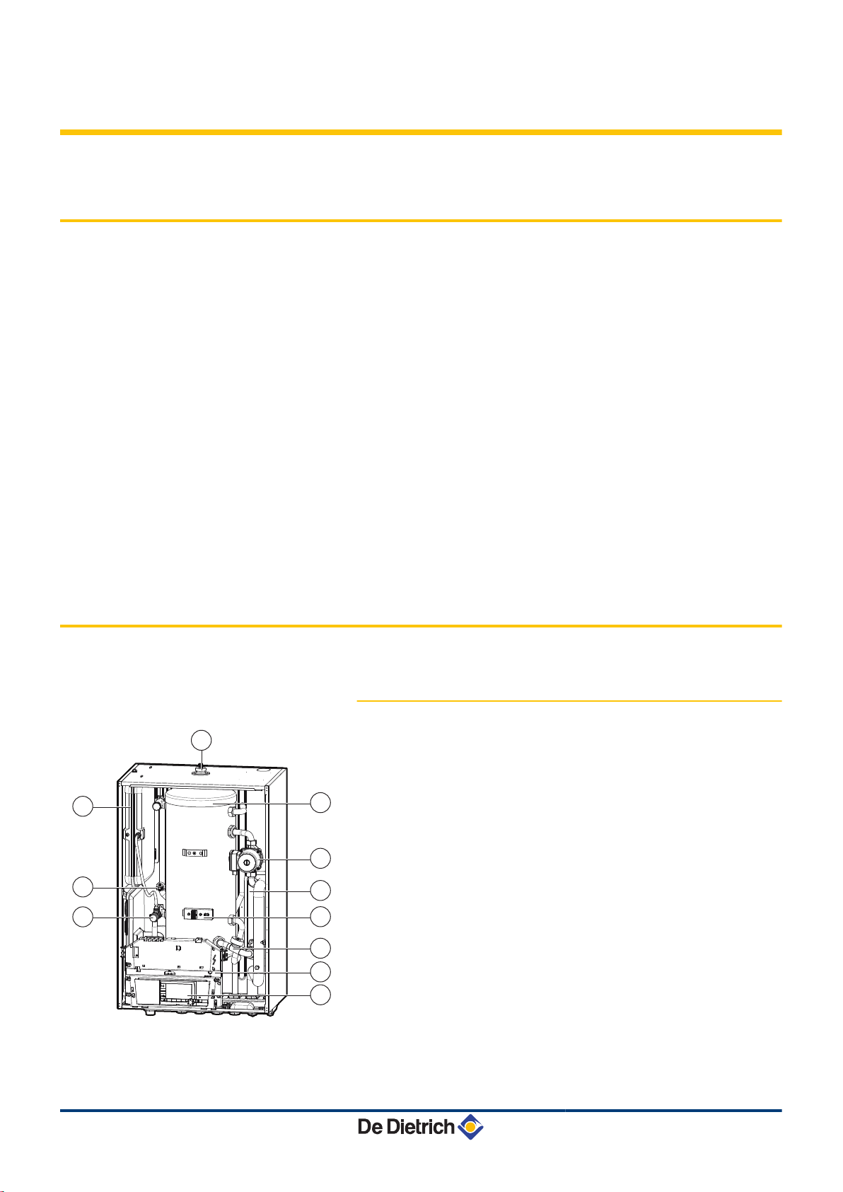
3.2 Main parts (Indoor module)
3.2.1. MIT-IN/H
1
2
3
4
5
6
7
8
9
10
11
Automatic air bleed
tank
High energy efficient heating pump
Plate heat exchanger
electrical support
Flowmeter
Table cover unit
Control panel
Safety valve
Pressure gauge
Expansion vessel
11
24/09/2012 - 300027606-001-01
Page 13
M002484-A
13
2
3
5
4
8
7
6
11
10
9
1
12
AWHP MIT-IN iSystem
3. Technical description
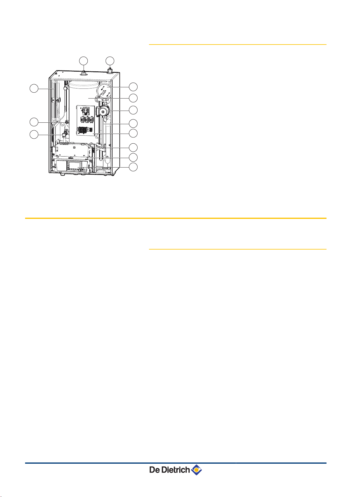
3.2.2. MIT-IN/E
3.3 Operating principle
1
2
3
4
5
6
7
8
9
10
11
12
13
Automatic air bleed
tank
High energy efficient heating pump
Plate heat exchanger
electrical support
Flowmeter
Table cover unit
Control panel
Safety valve
Pressure gauge
Expansion vessel
Automatic air bleed
Electric heater
3.3.1. General
The outside module produces heat or cold (in reversible versions) and
transmits it to the heating circuit via the refrigerant in the plate
exchanger.
The outside module is capable of operating at outside temperatures
down to -20°C (-15°C in the case of a 6MR or 8MR heat pump).
The DIEMATIC iSystem control panel is used to programme and
regulate the heat pump according to the outside temperature.
By activating the pumps and, where necessary, the mixer valve, the
regulator handles the regulation of the heating.
Connection of a CDR4 simplified remote control or a CDI4 interactive
remote control enables the auto-adaptivity of the gradient and the
parallel offset of the heating curve.
The antifreeze function on the installation is active whatever the
operating mode. It is triggered as soon as the outdoor temperature
reaches the limiting value preset to +3°C.
The installation of a buffer tank is not necessary if the volume of water
in the circuit is higher than or equal to 3 litres/kW: Therefore, for a
heat pump with an output of less than 11 kW, with a water volume of
less than 33 litres, the installation of a buffer tank is necessary.
24/09/2012 - 300027606-001-01
12
Page 14
M002487-D
MIT-IN H
AWHP
M002488-D
MIT-IN E
AWHP
1
6
4
5
2
3
3. Technical description AWHP MIT-IN iSystem
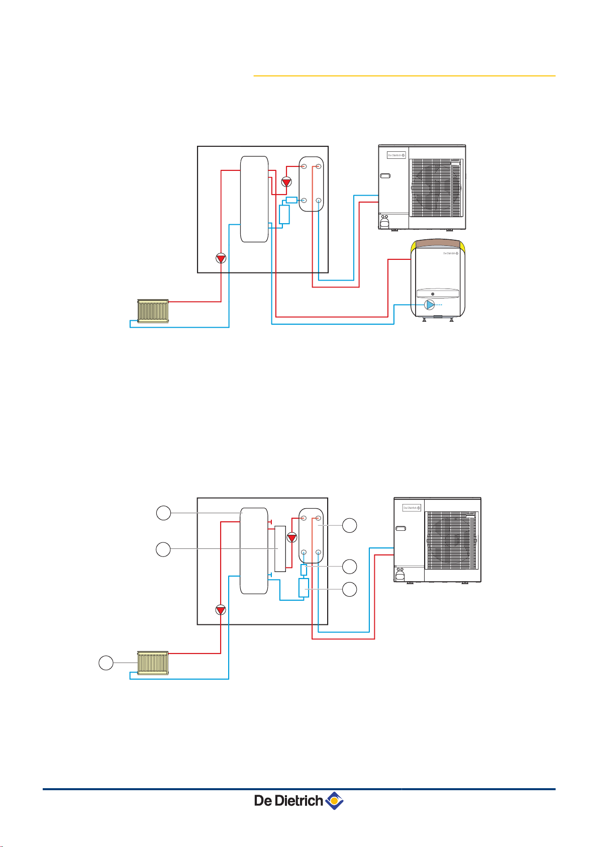
3.3.2. Skeleton Diagrams
MIT-IN/H
n
1
2
3
4
5
6
MIT-IN/E
n
tank
Filter
Flowmeter
Radiator
Plate heat exchanger
Boiler
13
1
2
3
4
5
tank
Filter
Flowmeter
Radiator
Plate heat exchanger
24/09/2012 - 300027606-001-01
Page 15
M002627-C
0
100
200
300
400
500
600
700
800
0 0,5 1 1,5 2 2,5 3
1
2
4
3
2
1
5
AWHP MIT-IN iSystem
3. Technical description
6
Electrical back-up
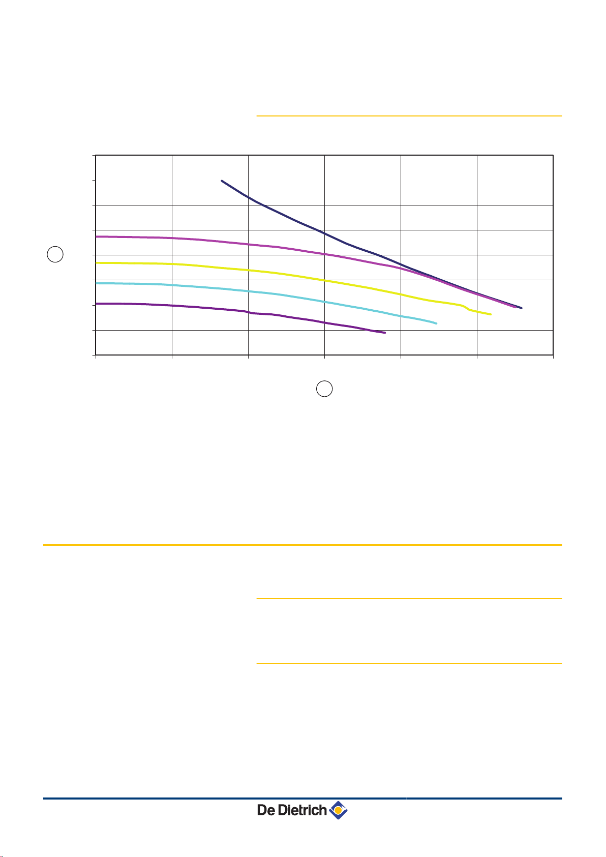
3.3.3. Pressure available
A
Z
1 - 5
¼ To set the speed of the heating pump correctly, refer to
chapter: "Setting the speed of the heating pump on the inside
module", page 86.
Pressure available (mbar)
Water flow rate (m3/h)
Setting the pump
3.4 Technical specifications
3.4.1. Electricity supply
230 V AC (+/- 10%) - 50 Hz
3.4.2. Heat pump
Conditions of use:
4 Limit operating temperatures in Hot mode:
- Water: +18 °C / +55 °C
- Outside air:
-15 °C / +35 °C (AWHP 6 MR, 8 MR)
-20 °C / +35 °C (AWHP 11-27)
4 Limit operating temperatures in Cooling mode:
24/09/2012 - 300027606-001-01
14
Page 16

3. Technical description AWHP MIT-IN iSystem
- Water: +7 °C / +25 °C
- Outside air: +15 °C / +40 °C (At less than 18°C, it is necessary
to use the HK24 insulation kit option)
4 Maximum operating pressure: 3 bar
AWHP
Calorific output - A7/
(1)
W35
COP hot - A7/W35
(1)
Absorbed electrical
power - A7/W35
(1)
Nominal amperage A7/W35
(1)
Calorific output - A2/
(2)
W35
COP hot - A2/W35
(2)
Absorbed electrical
power - A2/W35
(2)
Nominal amperage A2/W35
Cooling output
EER
(2)
(3)
(3)
Absorbed electrical
(3)
power
Sound pressure
(4)
Nominal water flow (ΔT
6 MR 8 MR 11 MR 11 TR 14 MR 14 TR 16 MR 16 TR 22 TR 27 TR
kW 6.0 8.5 10.9 10.9 13.7 13.7 15.7 15.7 19.4 24.4
4.00 4.10 4.23 4.23 4.03 4.03 3.90 3.90 3.94 3.90
kWe 1.5 2.1 2.6 2.6 3.4 3.4 4.03 4.03 4.9 6.3
A 6.8 9.2 11.2 6.7 14.8 8.8 17.6 10.1 12.3 15.6
kW 4.4 5.9 7.6 7.6 10.3 10.3 10.4 10.4 11.6 14.7
3.12 3.12 3.10 3.10 3.10 3.10 3.10 3.10 3.11 3.10
kWe 1.4 1.9 2.5 2.5 3.3 3.3 3.4 3.4 3.9 4.7
A 6.1 8.2 10.7 6.2 14.5 8.3 14.6 8.4 9.7 11.8
kW 5.4 7.9 10.5 10.5 11.7 11.7 11.7 11.7 17.7 22.2
3.80 3.99 4.68 4.68 4.43 4.43 4.43 4.43 3.8 3.8
kWe 1.4 2.0 2.2 2.2 2.7 2.7 2.7 2.7 4.6 5.8
dBA 36 36 40 40 41 41 41 41 45 45
1.04 1.47 1.88 1.88 2.34 2.34 2.67 2.67 3.8 4.6
m3/h
= 5K)
Manometric height
mbar 618 493 393 393 282 282 213 213 - available at nominal
flow rate
Nominal air flow rate
Power voltage of the
2100 3000 6000 6000 6000 6000 6000 6000 8400 8400
m3/h
V 230 V~ 230 V~ 230 V~ 400 V3~ 230 V~ 400 V3~ 230 V~ 400 V3~ 400 V3~ 400 V3~
outdoor unit
Sound output
(5)
dBA 63.7 65.2 65.4 65.4 66.8 66.8 69.4 69.4 67 67
R410A refrigerant kg 2.5 3.6 5 5 5 5 5 5 7.1 7.7
Refrigeration
inch 1/4-1/2 3/8-5/8 3/8-5/8 3/8-5/8 3/8-5/8 3/8-5/8 3/8-5/8 3/8-5/8 3/8-3/4 1/2-3/4
connection (LiquidGas)
Max pre-loaded length m 30 30 30 30 30 30 30 30 30 30
Weight (empty) -
kg 45 75 121 135 116 130 116 130 135 141
outside unit
(1) Hot mode: Outside air temperature +7 °C, Water temperature at the outlet +35 °C. Performances in line with EN 14511-2.
(2) Hot mode: Outside air temperature +2 °C, Water temperature at the outlet +35 °C. Performances in line with EN 14511-2.
(3) Cooling mode: Outside air temperature +35 °C, Water temperature at the outlet +18 °C. Performances in line with EN 14511-2
(4) 5 m from the appliance, free field.
(5) Test conducted in accordance with the standard NF EN 12102
3.4.3. Sensor characteristics
Outside sensor
Temperature in °C -20 -16 -12 -8 -4 0 4 8 12 16 20 24
Resistance in Ω 2392 2088 1811 1562 1342 1149 984 842 720 616 528 454
15
24/09/2012 - 300027606-001-01
Page 17

AWHP MIT-IN iSystem 3. Technical description
DHW sensor
Flow sensor
Temperature in °C 0 10 20 25 30 40 50 60 70 80 90
Resistance in Ω 32014 19691 12474 10000 8080 5372 3661 2535 1794 1290 941
24/09/2012 - 300027606-001-01
16
Page 18
4. Installation AWHP MIT-IN iSystem
4 Installation
4.1 Regulations governing installation
CAUTION
Installation of the appliance must be done by a qualified
engineer in accordance with prevailing local and national
regulations.
4.2 Package list
4.2.1. Standard delivery
The delivery includes:
4 An outside module (See below)
4 An inside hydraulic module (See below)
4 An outside sensor
4 A mounting rail (screwed to the pallet)
4 The installation and maintenance instructions
4 The user instructions
Description
AWHP 6 MR EH136
AWHP 8 MR EH96
AWHP 11 MR EH97
AWHP 11 TR EH98
AWHP 14 MR EH99
AWHP 14 TR EH100
AWHP 16 MR EH101
AWHP 16 TR EH102
AWHP 22 TR EH225
AWHP 27 TR EH226
Inside modules
MIT-IN/E 6-8 kW HK3
MIT-IN/H 6-8 kW HK8
MIT-IN/E 11-16 kW HK4
MIT-IN/H 11-16 kW HK9
MIT-IN/E 22-27 kW HK5
MIT-IN/H 22-27 kW HK10
Pack no.
17
24/09/2012 - 300027606-001-01
Page 19

AWHP MIT-IN iSystem 4. Installation
4.2.2. Accessories
Various options are available depending on the configuration of the
installation:
Description package
DHW sensor AD212
Optional PCB for 3-way valve AD249
System sensor AD250
Outside radio-controlled temperature sensor AD251
Radio module AD252
Radio remote control AD253
Interactive remote control AD254
160 L storage tank EH 60
80 L storage tank EH 85
Wall-hanging kit for outside units EH 95
Condensate receiver tank for wall bracket EH 111
Ground mounting supports for outside units EH 112
Electrical resistor for the condensate receiver tank EH 113
Frigorific ducts with insulation (5/8" - 3/8"); Length: 5 m EH 114
Frigorific ducts with insulation (5/8" - 3/8"); Length: 10 m EH 115
Frigorific ducts with insulation (5/8" - 3/8"); Length: 20 m EH 116
Insulated copper pipe (1/2" - 1/4") 10 m EH 142
1/4" 1/2" - 3/8" 5/8" adapter fittings EH 146
3-way valve module with standard pump EA 63
3-way valve module with electronic pump EA 67
Wiring kit for connecting a safety thermostat for underfloor
heating
3-way valve kit HK 21
2-circuit kit HK 22
Reversal valve kit HK 23
Insulation kit cold mode HK 24
3-way valve insulation kit HK 25
Condensation detector kit HK 27
HA 249
24/09/2012 - 300027606-001-01
18
Page 20
Brrrrr....
Brrrrr....
Brrrrr....
Brrrrr....
C000373-B
M002624-A
Auf ERDGAS H eingestellt
für DE: Erdgas E
Réglé au gaz naturel H
Geregeld voor aardgas H
Preset for natural gas H
G20 - 20 mbar
8366-4038
1 2
M001448-A
4. Installation AWHP MIT-IN iSystem
4.3 Data plate
1
2
The rating plate must be accessible at all times. The rating plate
identifies the product and provides the following information:
4 Appliance type
4 Manufacturing date (Year - Week)
4 Serial number.
4 Nature of the power supply voltages
4.4 Installing the outdoor module
4.4.1. Location of the appliance
This data plate is affixed to the inside side panel of the
appliance in the factory.
When installation has been completed, affix the data plate
provided in the instructions bag to the casing of the
appliance in a position where it can be seen.
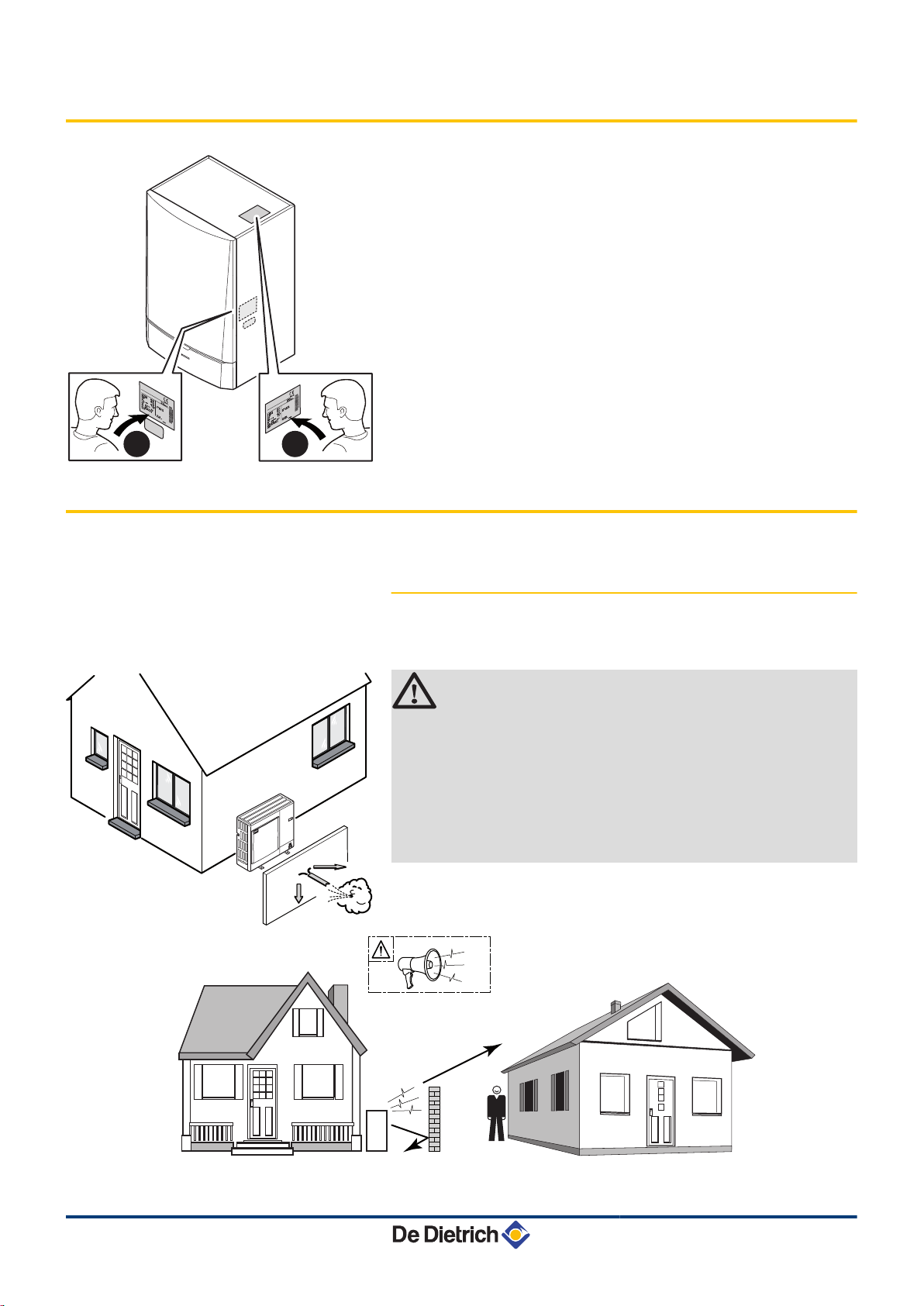
Ensure that the outside module is optimally positioned in relation to
neighbours as it is a source of noise.
CAUTION
4 There must be no obstacles hindering the free
circulation of air around the outdoor module (intake
and output).
4 No not locate the outside unit close to where people
sleep.
4 Do not locate the unit opposite a wall with windows.
4 Avoid placing it close to a terrace, etc..
Choose a location away from prevailing winds.
19
24/09/2012 - 300027606-001-01
Page 21
M00 1439-A
A
B
2
1
C
AWHP MIT-IN iSystem 4. Installation
In some cases, additional precautions are necessary owing to the
fact, for example, of too short a distance between you and your
neighbours.
When installing a noise reduction screen, respect the following
recommendations:
4 Locate the noise reduction screen as close as possible to the noise
source whilst allowing for the free circulation of air in the
exchanger on the outside unit and maintenance work.
Place the outside unit on a base (concrete base frame, sill,
concrete blocks, etc.) with no rigid connection with the building
served in order to prevent any transmission of vibrations. Ensure
sufficient above ground elevation (100 to 150 mm) to keep it above
water.
For regions where heavy snowfalls occur, raise this above ground
protection by at least 200 mm compared with the average depth of
the covering of snow.
CAUTION
If the outside temperatures become negative, take the
necessary precautions to prevent the risk of freezing in the
evacuation pipes.
Prevent any risk of the condensates freezing in an area
through which they flow.
The heating cord keeps the condensates from freezing:
See EH113 leaflet.
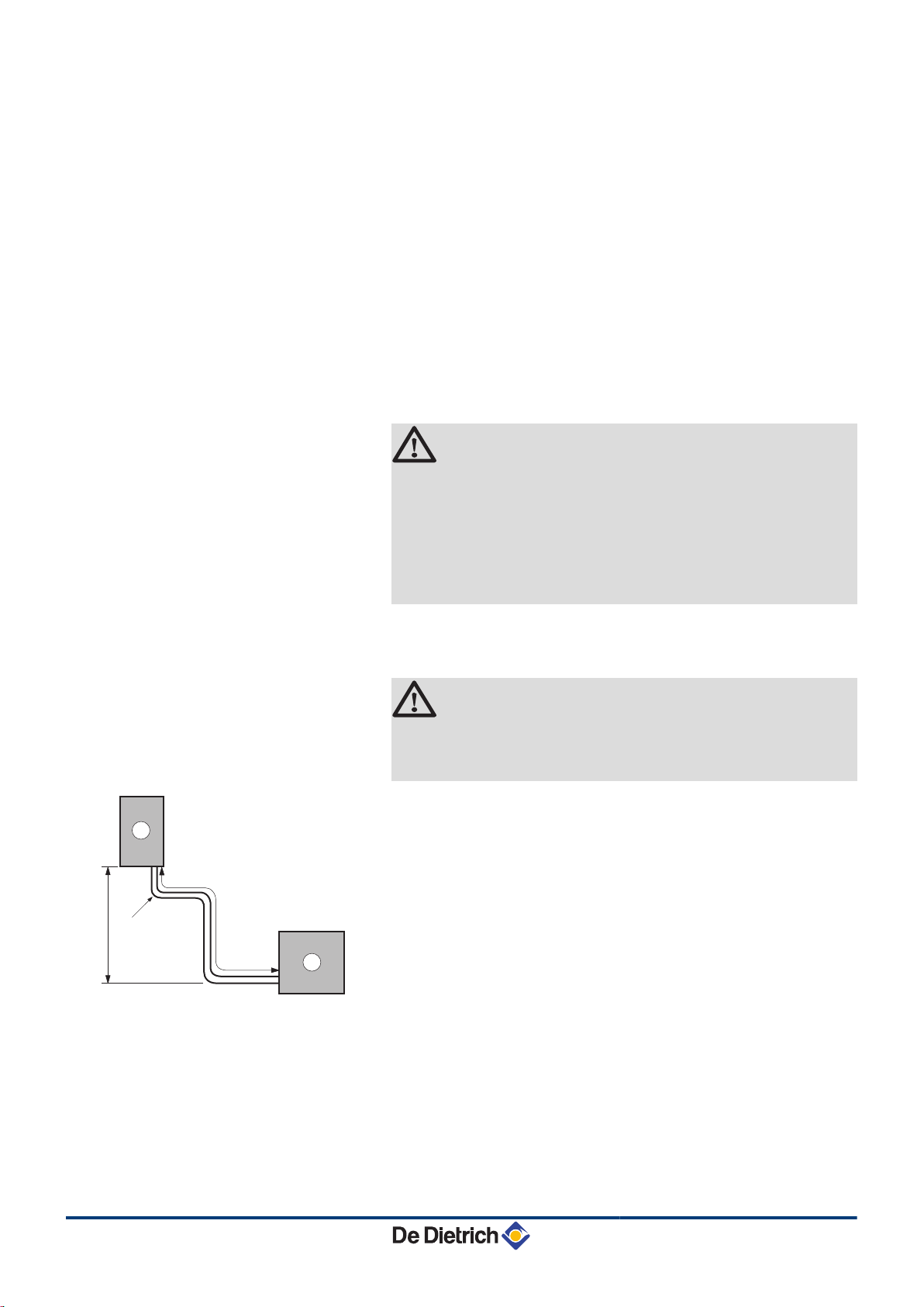
Distances to be observed
n
WARNING
To ensure that the heat pump functions correctly, respect
the minimum and maximum connection lengths between
the heat pump and the indoor module.
A
Z
A
Outside module
Indoor module
Minimum length 5 m
Maximum length: 50 m for AWHP 6-8 MR,
75 m for AWHP 11-14-16 MR/TR,
20 m for AWHP 22-27 TR.
B
C
Max height difference 30 m
Max number of elbows: 15
Respect the minimum curve radii of 100 to 150 mm
24/09/2012 - 300027606-001-01
20
Page 22
M001450-B
G
F
F
G
A
C
B
B
C
E
A
1000
D
Max. 500
Max. 500
4. Installation AWHP MIT-IN iSystem
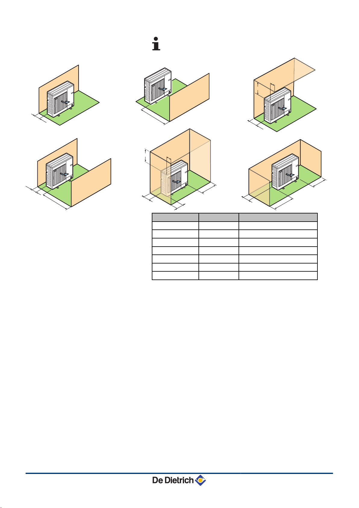
¼ See chapter: "Installing the pipes", page 30.
Dimension (mm) AWHP 6-8 MR AWHP 11-14-16-22-27 MR-TR
A
B
C
D
E
F
G
100 150
500 1000
200 300
1000 1500
300 500
150 250
100 200
21
24/09/2012 - 300027606-001-01
Page 23
M002199-A
150 500
800
887
300
183
155
365
600
40
10
23
69
18
90
5
6
AWHP MIT-IN iSystem 4. Installation
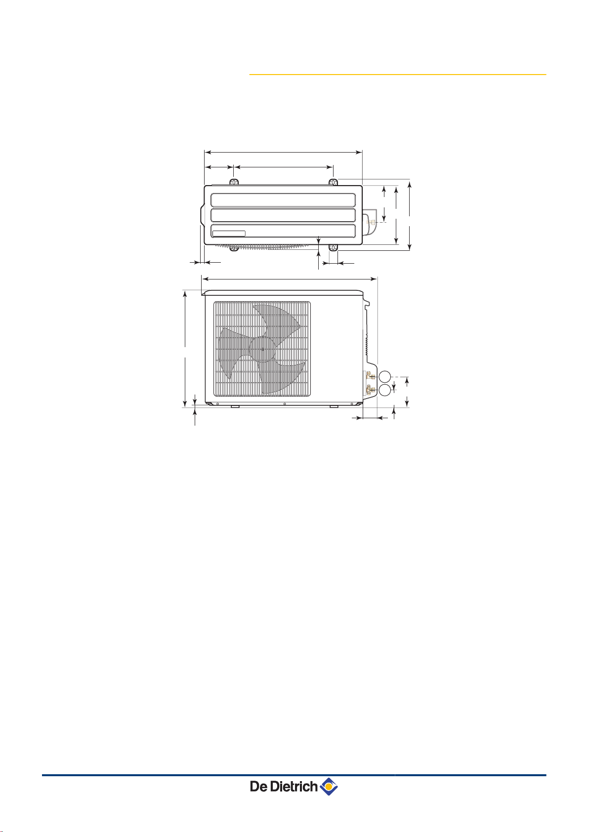
4.4.2. Main dimensions
AWHP 6 MR
n
T
Y
1/4" flare refrigerant fitting
1/2" flare refrigerant gas fitting
24/09/2012 - 300027606-001-01
22
Page 24
943
950
45
56
53 28
19
23
417
175
330
370
30
443
447
175
65 42
6
5
6
M001442-C
5
4. Installation AWHP MIT-IN iSystem
AWHP 8 MR
n
T
Y
3/8" flare refrigerant fitting
5/8" flare refrigerant gas fitting
23
24/09/2012 - 300027606-001-01
Page 25
M002394-C
1350
950
45
56
53 28
19
23
417
175 600
330
370
30
443
447
175
65 42
6
5
6
5
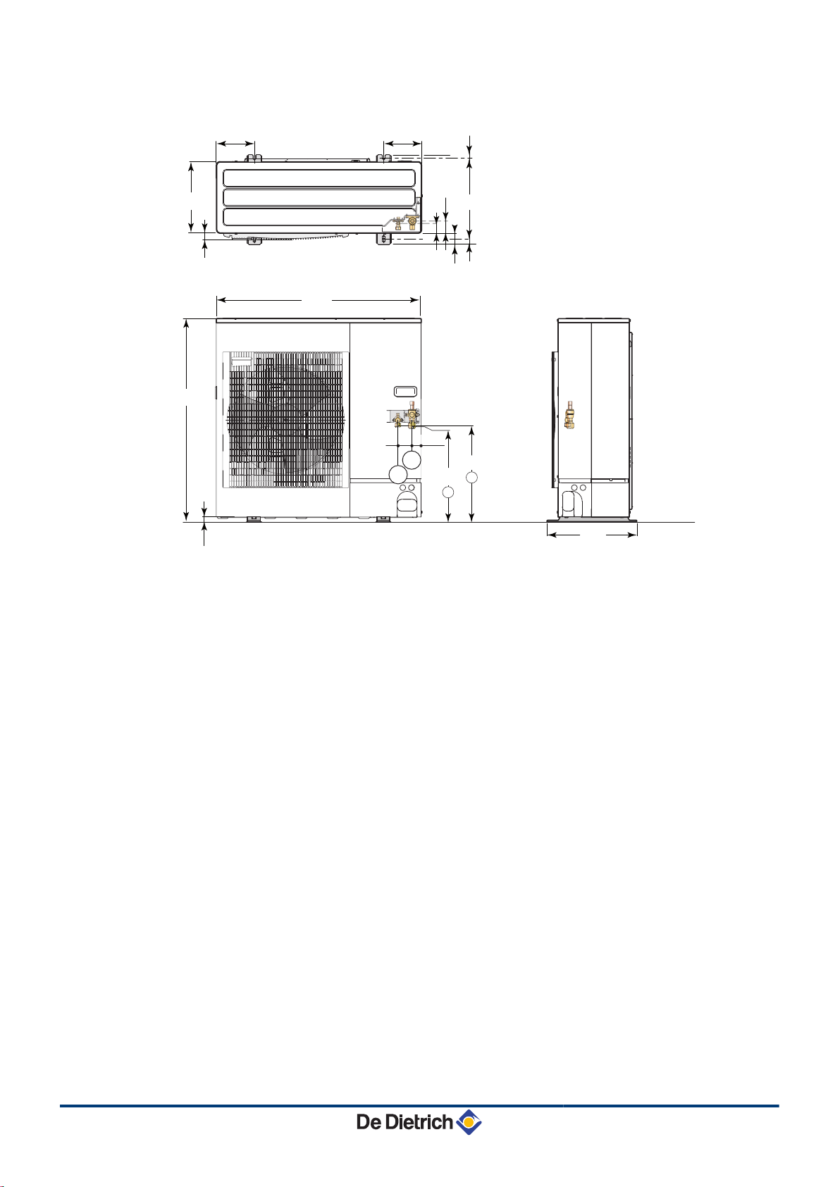
AWHP MIT-IN iSystem 4. Installation
AWHP 11 to 16
n
T
Y
3/8" flare refrigerant fitting
5/8" flare refrigerant gas fitting
24/09/2012 - 300027606-001-01
24
Page 26
M002629-A
1338
1050
40
56
26
342
A
225
330
370
417
30
600 225
19
28
60
42
5
6
6
5
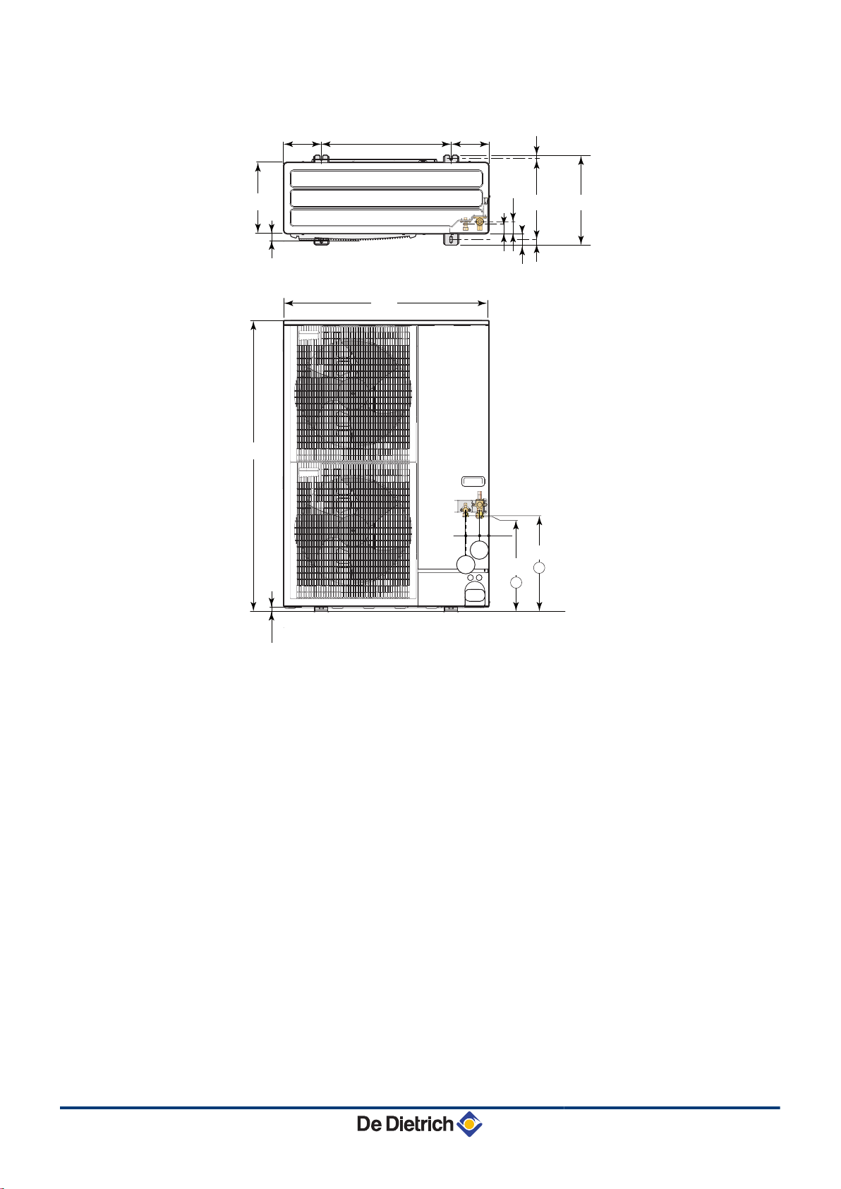
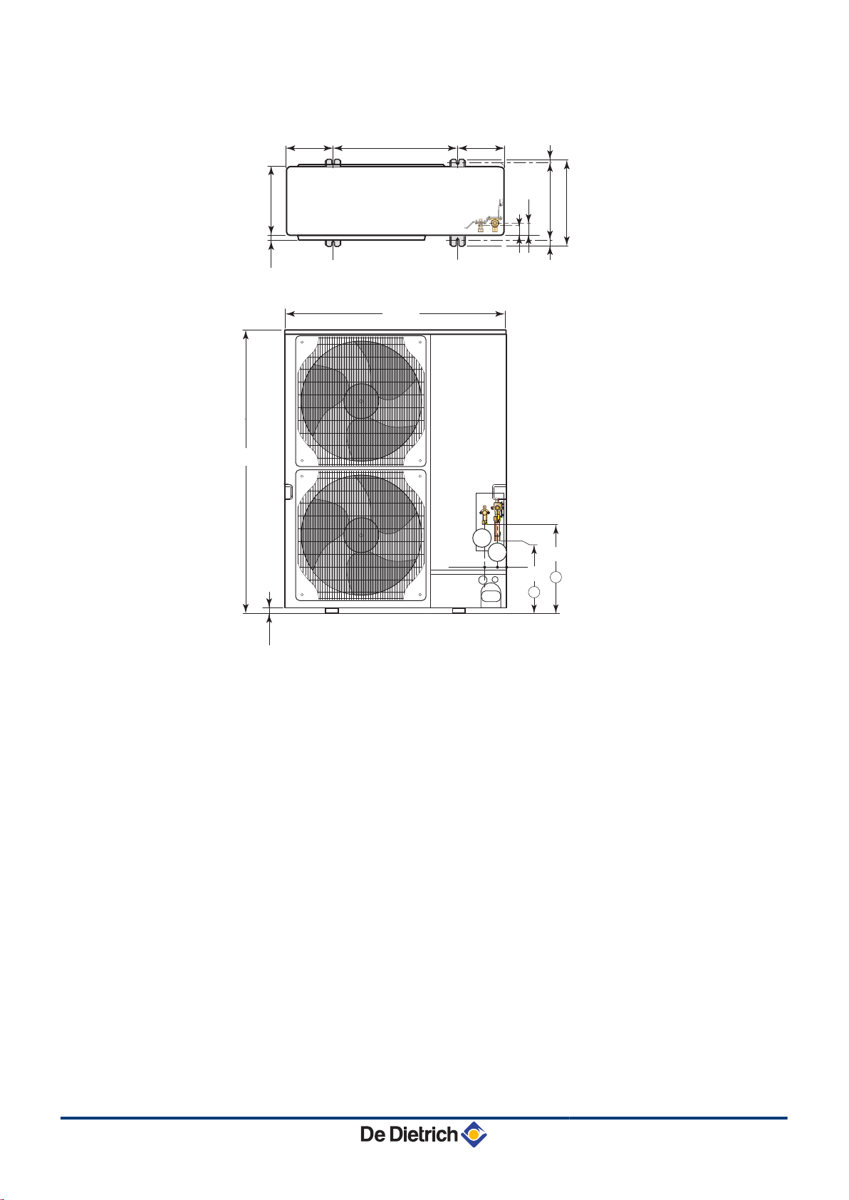
4. Installation AWHP MIT-IN iSystem
AWHP 22 to 27
n
A
T
AWHP 22 : 450
AWHP 27 : 424
3/8" flare refrigerant fitting (AWHP 22)
1/2" flare refrigerant fitting (AWHP 27)
Y
3/4" flare refrigerant gas fitting
25
24/09/2012 - 300027606-001-01
Page 27
>45°
M001456-A
200
1
2
3
M001452-A
AWHP MIT-IN iSystem 4. Installation
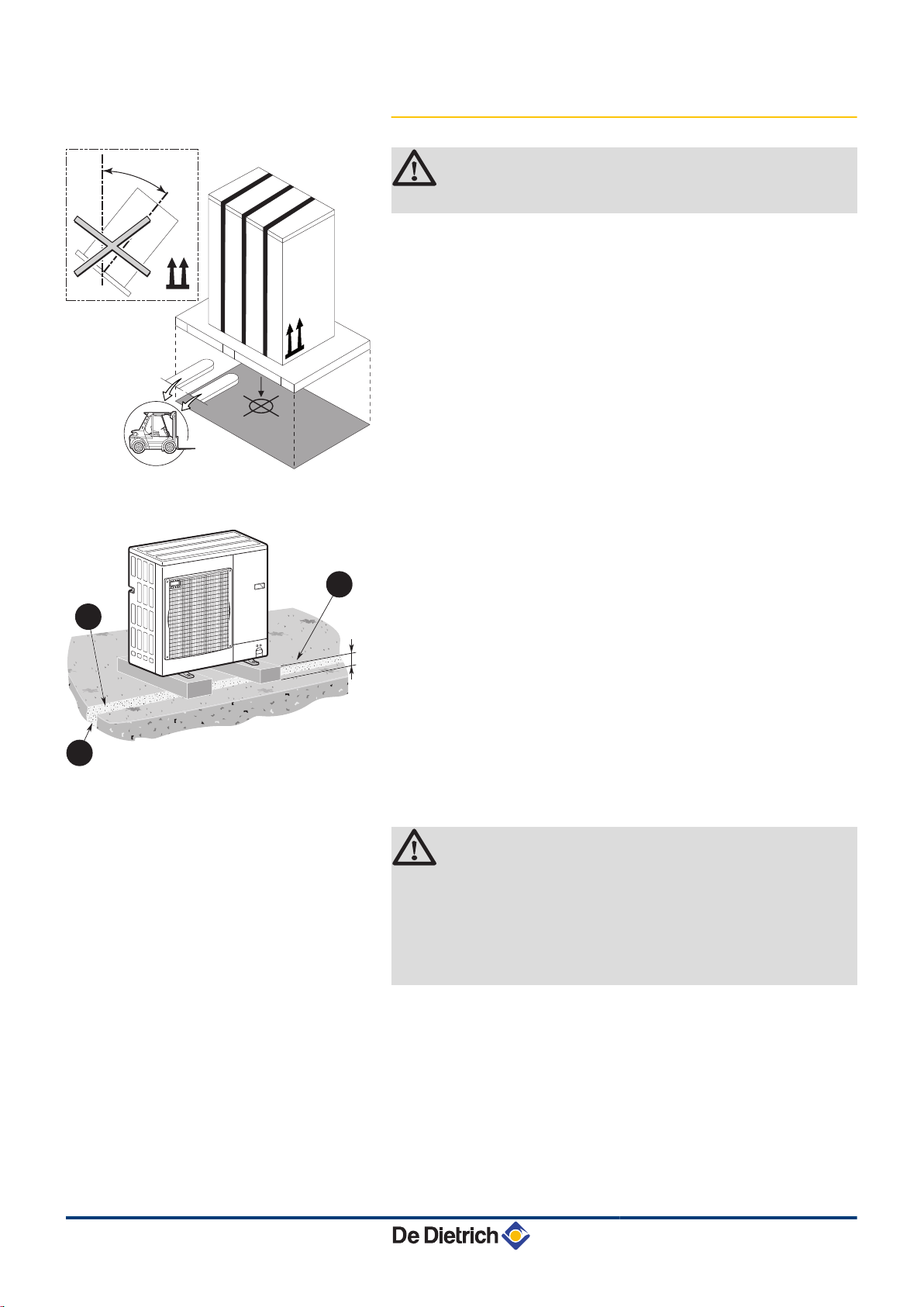
4.4.3. Locating the outside module
CAUTION
Keep the appliance vertical during transport.
Installation on the ground
n
1
2
3
Concrete base frame
Condensates run-off
Install a run-off channel with pebble bed
4 Use the ground installation base kit available as optional
equipment: Package EH112.
4 Install the appliance on a solid, stable structure able to bear its
weight.
Condensates discharge
n
CAUTION
If the outside temperatures become negative, take the
necessary precautions to prevent the risk of freezing in the
evacuation pipes. Use package EH113 (Electrical resistor
for the condensate receiver tank).
Prevent any risk of the condensates freezing in an area
through which they flow.
24/09/2012 - 300027606-001-01
26
Page 28
T001898-C
600
min.1000
500
min.
250
min.
250
900
M002497-B
122
192
262
332
402
472
542
49 48
900
600
498
1234567
8
4. Installation AWHP MIT-IN iSystem
4.5 Installing the indoor module
4.5.1. Location of the appliance
CAUTION
4 Install the appliance in frost-free premises.
4 Fix the appliance to a solid wall capable of bearing
the weight of the appliance when full of water and fully
equipped.
4.5.2. Main dimensions
A
Z
E
R
T
Y
U
I
G
3-way valve circuit return (Option) - G1"
3-way valve circuit outlet (Option) - G1"
Return direct circuit - G1"
Direct circuit flow - G1"
Back-up boiler inlet - G1"
Only MIT-IN/H
Return to the back-up boiler - G1"
Only MIT-IN/H
Gas line
AWHP 6-16: 5/8" flare connection
AWHP 22-27: 3/4" flare connection
Liquid line
AWHP 6-16: 3/8" flare connection
AWHP 22-27: 1/2" flare connection
Exterior cylindrical threading, sealed by sheet gasket
27
24/09/2012 - 300027606-001-01
Page 29
1
2
3
3
M002380-B
458
61
11
558
Ø10
M002381-C
AWHP MIT-IN iSystem 4. Installation
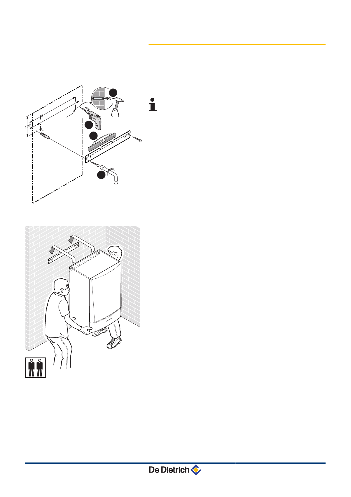
4.5.3. Assembly of the MIT indoor module
Fitting the mounting rail
n
1. Drill 2 holes with a Ø of 10 mm.
Additional holes are provided in case one or other of the
standard locating holes prevents the correct location of the
plugs.
2. Put the plugs in place.
3. Fix the mounting rail to the wall using the hexagonal head screws
provided for this purpose. Set the level using a spirit level.
Fixing to the wall
n
1. Present the indoor module above the mounting rail until it rests
firmly against it.
2. Gently lower the indoor module.
24/09/2012 - 300027606-001-01
28
Page 30
8800N001-C
8800N002-C
4. Installation
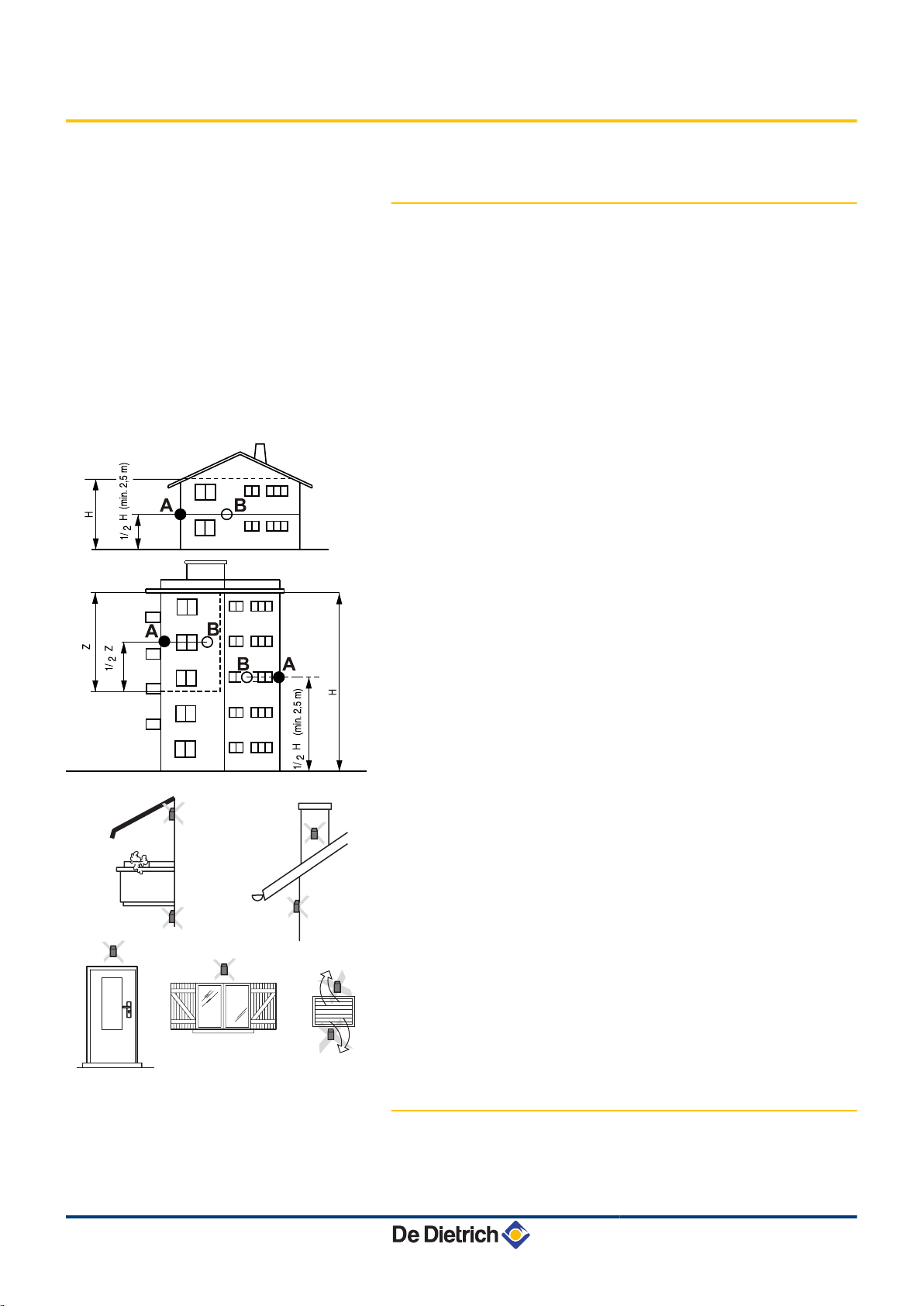
4.6 Installing the outside sensor
4.6.1. Choice of the location
It is important to select a place that allows the sensor to measure the
outside conditions correctly and effectively.
Advised positions:
4 on one face of the area to be heated, on the north if possible
4 half way up the wall in the room to be heated
4 under the influence of meteorological variations
4 protected from direct sunlight
4 easy to access
AWHP MIT-IN iSystem
A
B
H
Z
Recommended position
Possible position
Inhabited height controlled by the sensor
Inhabited area controlled by the sensor
Positions to be avoided:
4 masked by a building element (balcony, roof, etc.)
4 close to a disruptive heat source (sun, chimney, ventilation grid,
etc.)
29
4.6.2. Connecting the outside sensor
Mount the sensor using the screws and dowels provided.
24/09/2012 - 300027606-001-01
Page 31

8800N003-C
2
AWHP MIT-IN iSystem
4. Installation
A
Z
Inserts
Ø4 wood screw
¼ For the connection of the outside temperature sensor, refer to
the chapter "Electrical Connections".
4.7 Combination with a DHW tank
In order to optimise domestic hot water production, the recommended
combinations of heat pumps and DHW tanks are:.
BL150 X X X
BL200 X X X X X
BL300
AWHP 6MR AWHP 8MR AWHP 11MR-TR AWHP 14MR-TR AWHP 16MR-TR AWHP 22TR AWHP 27TR
X X X X X
WARNING
4.8 Refrigeration connection
An incorrect DHW tank/heat pump combination may
adversely affect user comfort.
An incorrect combination may lead to overconsumption
subsequent to the repeated tripping of the back-ups.
4.8.1. Installing the pipes
DANGER
Only a qualified professional may carry out the installation
in conformity with in force legislation and standards.
4 Install the frigorific connection pipes between the inside and
outside modules.
4 Respect the minimum curve radii of 100 to 150 mm.
4 Respect the minimum and maximum lengths. ¼ See
chapter: "Location of the appliance", page 19.
If the frigorific connection between the outside module and the
inside module is less than 5 m, the following disruptions may
occur:
- Functional disruptions caused by a fluid overload
- Noise pollution caused by the circulation of the refrigerant
In this case, fit a refrigerant connection of at least 5 m by making
1 or 2 horizontal loops, as necessary, in order to limit such
annoyance and oil traps.
24/09/2012 - 300027606-001-01
30
Page 32

L000276-A
M002395-B
1
M002396-B
OK
Pfffff...
2
4. Installation
AWHP MIT-IN iSystem
If the refrigeration connection pipes are more than 30 metres long,
refrigerant R410A must be added.
Add refrigerant via the refrigerant shut off valve using a safety loader.
Model Quantity of refrigerant to be added
31 to 40 m 41 to 50 m 51 to 60 m 61 to 75 m
AWHP 6 MR 0.2 kg 0.4 kg / /
AWHP 8 MR 0.6 kg 1.2 kg / /
AWHP 11-14-16 MR-TR0.6 kg 1.2 kg 1.8 kg 2.4 kg
AWHP 22 TR 0.9 kg 1.8 kg 2.7 kg 3.6 kg
AWHP 27 TR / / / /
4 Cut the pipes with a pipe cutter and deburr them, point the opening
in the pipe downwards to prevent the introduction of particles.
4 Prevent oil traps.
WARNING
If the pipes are not to be connected immediately, they
should be plugged to prevent the infiltration of humidity.
Use a flat spanner to hold the hoses during the various
operations.
1. Partially unscrew the 5/8" or 3/4" "gas" nut, depending on the
model.
2. A release noise should be heard, which is proof that the exchanger
is watertight.
31
24/09/2012 - 300027606-001-01
Page 33

M002397-C
3
M002498-A
4
M002398-D
6MR
5
M002399-D
22TR
5
M002207-B
6
7
AWHP MIT-IN iSystem
3. Unscrew the screws.
CAUTION
Keep the frigorific connection in place on the MIT with a
spanner so as not to twist the internal pipe.
4. Remove and discard the gates.
Only for the 6MR model
5.
Fit the 1/4" to 3/8" and 1/2" to 5/8" adapter fittings (Package
EH146).
Use the copper gaskets.
Use a dynamometric spanner.
See "torque" table (step 9).
¼
Only for the 22TR model
Fit a 3/8" to 1/2" adapter to the liquid connection.
Use the copper gaskets.
Use a dynamometric spanner.
See "torque" table (step 9).
¼
4. Installation
CAUTION
Keep the frigorific connection in place on the MIT with a
spanner so as not to twist the internal pipe.
Models 8 to 16
6.
Slip the nuts onto the pipes.
6MR
Slip the nuts provided with the adapters onto the pipes.
7. Bead the pipes.
24/09/2012 - 300027606-001-01
32
Page 34

M002400-B
8
22TR - 27TR
M002714-B
9
9
A B
10
10
M002402-A
4. Installation AWHP MIT-IN iSystem
Models 22TR to 27TR
8.
Slip the nut onto the pipe. Bead the pipes.
9.
A
Only for 6 MR models
B
For all models except 6 MR - 22 TR - 27 TR
Apply refrigerant oil to the beaded parts to facilitate tightening and
improve watertightness.
Connect the pipes and tighten the nuts with a dynamometric
spanner.
CAUTION
Keep the frigorific connection in place on the MIT with a
spanner so as not to twist the internal pipe.
External diameter of the
pipe (mm-inch)
6.35 - 1/4 17 14 - 18
9.52 - 3/8 22 34 - 42
12.7 - 1/2 26 49 - 61
15.88 - 5/8 29 69 - 82
19.05 - 3/4
External diameter of
the cone connection
(mm)
Torque load (Nm)
100 - 120
10.Remove the protective side panels from the outdoor module.
33
24/09/2012 - 300027606-001-01
Page 35

M002403-A
11
12
13
M002404-A
14
A
B
B
M002406-A
14
A
B
B
22TR - 27TR
AWHP MIT-IN iSystem 4. Installation
11.Unscrew the nuts on the shut off valves.
12.Slip the nuts onto the pipes.
13.Bead the pipes.
14.Apply refrigerant oil to the beaded parts to facilitate tightening and
improve watertightness.
Connect the pipes and tighten the nuts with a dynamometric
spanner.
A Do not use a spanner on this part of the valve, danger of the
refrigerant leaking.
B Recommended position of the spanners for tightening the nut.
CAUTION
Tighten the nuts using a dynamometric spanner.
External diameter of the
pipe (mm-inch)
6.35 - 1/4 17 14 - 18
9.52 - 3/8 22 34 - 42
12.7 - 1/2 26 49 - 61
15.88 - 5/8 29 69 - 82
19.05 - 3/4
External diameter of
the cone connection
(mm)
Torque load (Nm)
100 - 120
24/09/2012 - 300027606-001-01
34
Page 36

M002297-A
A
B
C
35 bar
M001470-B
M002297-A
A
B
C
M002499-B
M002295-B
A
B
D
D
4. Installation
AWHP MIT-IN iSystem
4.8.2. Water tightness test
1. Check that the shut off valves A and B are closed.
2. Connect the pressure gauge valve and the nitrogen cylinder to the
operating connection C on the shut off valve A.
3. Progressively pressurise the refrigerant connection pipes and the
indoor module in steps of 5 bar until you reach 35 bar.
4. Check the watertightness of the connections with a "leak detector"
spray. If leaks occur, redo and recheck tightness.
5. Release the pressure and release the nitrogen.
4.8.3. Evacuation
1. Check that the shut off valves A and B are closed.
2. Connect the vacuum gauge and the vaccuum pump to the
operating connection C and the shut off valve A.
3. Produce a vacuum in the indoor module and the refrigerant
connection pipes.
4. Check the pressure according to the recommendations table
below:
Outside temperature (°C)
Pressure to be reached (Pa) 1000 600 250 200
Draw-off evacuation time after reaching the
pressure (h)
10 0 - 10
20
ª
1 1 2 3
5. Close the valve between the vacuum gauge/vaccuum pump and
the shut off valve A.
6. After shutting off the vaccuum pump, immediately open the valves.
4.8.4. Opening the valves
1. Remove the cap D on the refrigerant off valve A.
2. Open the valve with a hexagonal spanner by turning anticlockwise until it stops.
3. Put the cap back in place.
4. Remove the cap D on the refrigerant gas shut off valve B.
5. Open the valve with a pair of pliers, turning it anticlockwise by a
quarter turn.
6. Put the cap back in place.
7. Disconnect the vacuum gauge and the vaccuum pump. Put the
cap back in place.
35
24/09/2012 - 300027606-001-01
Page 37

AWHP MIT-IN iSystem
4. Installation
8. Tighten the caps with a dynamometric spanner with a torque load
of 20 to 25 N·m.
9. Check the watertightness of the connections using a leak detector.
4.8.5. Adding refrigerant
If the refrigeration connection pipes are more than 30 metres long,
refrigerant R410A must be added. See table below.
Add refrigerant via the refrigerant shut off valve using a safety loader.
4.9 Hydraulic connections
Model (Outside
module)
AWHP 6 MR 0.2 kg 0.4 kg / /
AWHP 8 MR 0.6 kg 1.2 kg / /
AWHP 11-14-16 MR-TR0.6 kg 1.2 kg 1.8 kg 2.4 kg
AWHP 22 TR 0.9 kg 1.8 kg 2.7 kg 3.6 kg
AWHP 27 TR / / / /
Quantity of refrigerant to be added
31 to 40 m 41 to 50 m 51 to 60 m 61 to 75 m
¼ See chapter: "Main dimensions", page 27
4.9.1. Flushing the system
Installation must be carried out in accordance with the prevailing
regulations, the codes of practice and the recommendations in these
instructions.
Fitting the appliance to new installations
n
24/09/2012 - 300027606-001-01
4 Clean the installation with a universal cleaner to eliminate debris
from the appliance (copper, hemp, flux).
4 Thoroughly flush the installation until the water runs clear and
shows no impurities.
Fitting the appliance to existing installations
n
4 Remove sludge from the installation.
4 Flush the installation.
4 Clean the installation with a universal cleaner to eliminate debris
from the appliance (copper, hemp, flux).
4 Thoroughly flush the installation until the water runs clear and
shows no impurities.
36
Page 38

M002537-A
1 2
M002500-D
AWHP
230V
50Hz
BUS
21
51
230V
50Hz
EA63
9
11b
10
27
9
°C
°C
EA61
65
115
23
52
52
64
64
51
51
EA59
44
9
°C
27
°C
9
11a
MIT-IN H
HK22
4. Installation AWHP MIT-IN iSystem
4.9.2. Connection of the heating circuit
1. Connect the heating water return pipe to the heating return
connection.
: Screw-on connection ∅ 1"
z
2. Connect the heating water outlet pipe to the heating flow
connection.
: Screw-on connection ∅ 1"
{
4 The device is factory-fitted with a safety valve.
CAUTION
4 The heating pipe must be mounted in accordance
with prevailing provisions.
4.9.3. Hydraulic connection diagrams
CAUTION
The maximum volume scheduled for the installation is
215 litres. If this volume is exceeded in relation to the
internal expansion vessel, add an external expansion
vessel.
Example of connecting a system with MIT-IN/H
n
37
24/09/2012 - 300027606-001-01
Page 39

M002501-D
AWHP
230V
50Hz
230V
50Hz
BUS
21
65
115
23
64
51
44
HK23
HK21
MIT-IN E
A
B
A/B
AWHP MIT-IN iSystem 4. Installation
Example of connecting a system with MIT-IN/E
n
3
4
7
9
11a
3-bar safety valve
Pressure gauge
Automatic air vent
Isolating valve
Automatically regulated electronic pump for direct heating
circuit
11b
16
17
18
21
22
23
24
25
26
27
Pump for heating circuit with mixing valve
Closed expansion vessel
Drain cock
Filling the heating circuit
Exterior temperature sensor
Boiler temperature sensor
Mixing valve outlet temperature sensor
DHW calorifier exchanger primary inlet
DHW calorifier heat exchanger primary outlet
DHW load pump
Non-return valve
24/09/2012 - 300027606-001-01
28
29
Domestic cold water inlet
Pressure reducer if supply pressure exceeds 80 % of the
safety valve pressure setting
30
33
Calibrated and sealed safety unit
Domestic hot water temperature sensor
38
Page 40

4. Installation AWHP MIT-IN iSystem
4.10 Filling the heating system
34
44
50
51
52
56
57
64
65
89
115
Primary pump
Safety thermostat
Disconnector
Thermostat valve
Differential valve
Domestic hot water circulation loop return
Domestic hot water outlet
Direct heating circuit
Heating circuit with mixing valve
Heat transfer fluid container
Thermostatic distribution valve for each zone
4.10.1. Water treatment in the heating circuit
In a number of cases, the heat pump and the central heating system
can be filled with normal tap water and no water treatment is
necessary.
WARNING
4 Do not add chemical products to the central heating
water without first consulting a water treatment
professional. For example: antifreeze, water
softeners, products to increase or reduce the pH
value, chemical additives and/or inhibitors. Chemical
products may cause malfunctions on the heat pump
and damage the heat exchanger.
4 Do not use hydrochloric acid-based cleaning or
descaling products.
CAUTION
4 Check the compatibility of the product with the
materials used in the installation.
4 Check the compatibility of the product with stainless
steel and copper.
4 Respect the manufacturer's instructions (use, dose,
etc.) to obviate any hazards (corporal, material,
environmental).
4 An uncleaned installation or an installation using
water of unsuitable quality may bring about the
cancellation of the warranty.
39
24/09/2012 - 300027606-001-01
Page 41

AWHP MIT-IN iSystem
4. Installation
4 Rinse the central heating installation with at least 3x
the volume of the central heating installation.
4 Flush the DHW pipes with at least 20 times the volume
of the pipes.
For an optimum functioning of the boiler, the water of the installation
must comply with following characteristics:
Acidity (pH)
Conductivity at 25°C µS/cm 10 to 500
Chlorides mg/l < 50
Other components mg/l < 1
Hardness of the water of the installation °f 7- 15
°dH 4- 8.5
Output ≤ 70 kW
7.5 - 9
4.10.2. Filling the system
If a water treatment is necessary, De Dietrich
Thermique recommends the following manufacturers:
4 Cillit
4 Climalife
4 Fernox
4 Permo
4 Sentinel
CAUTION
Do not use glycol.
The heat pump components are not designed to be used
with glycol.
The use of glycol in the heating circuit invalidates the
warranty.
4 Fill the installation until a pressure of 1.5 to 2 bars is reached.
Water pressure display: See chapter: ¼ "Reading out
measured values", page 88.
4 Check for any water leaks.
4 Completely vent the indoor module and the installation for
optimum functioning.
24/09/2012 - 300027606-001-01
40
Page 42

4. Installation AWHP MIT-IN iSystem
4.11 Electrical connections
4.11.1. Recommendations
WARNING
4 Only qualified professionnals may carry out electrical
connections, always with the power off.
4 Earth the appliance before making any electrical
connections.
Make the electrical connections of the appliance according to:
4 The instructions of the prevailing standards,
4 The instructions on the circuit diagrams provided with the
appliance,
4 The recommendations in the instructions.
The earthing shall comply with local standards.
CAUTION
4 Separate the sensor cables from the 230/400 V
circuit cables.
4 The installation must be fitted with a circuit breaker
disconnecting switch.
4 Three phase models must always be fitted with
neutral.
Power the appliance via a circuit which includes a remote omnipolar
switch with a gap of more than 3 mm.
4 Single phase models: 230 V AC (+6%/-10%) 50 Hz
4 Three phase models: 400 V AC (+6%/-10%) 50 Hz
When making electrical connections to the mains, respect the
following polarities:
4 Brown wire: Live
4 Blue wire: Neutral
4 Green/yellow wire: Earth
41
WARNING
Secure the cable with the cable clamp provided.
Be careful that you do not invert the wires.
24/09/2012 - 300027606-001-01
Page 43

AWHP MIT-IN iSystem 4. Installation
4.11.2. Recommended cable cross section
The electrical characteristics of the mains power supply available
must correspond to the values given on the rating plate.
The cable will be carefully chosen according to the following
information:
4 Maximum intensity of the outdoor module. See table below.
4 Distance of the appliance from the original power supply.
4 Upstream protection.
4 Neutral operating conditions.
Appliance
AWHP
6 MR 8 MR 11 MR 11 TR 14 MR 14 TR 16 MR 16 TR 22 TR 27 TR
MIT-IN
Outside
module
Absorbed
electrical
kW 1.50 2.10 2.59 2.59 3.45 3.45 4.03 4.03 5.6 6.9
power
Nominal
A 6.8 9.34 11.2 3.98 14.8 5.37 17.7 5.99 13.9 17.2
amperage
Maximal
A 13 19 28 13 28 13 29 13 19 21
amperage
(1)
Type
Power supply
S-C
(2)
Curve D
(3)
DJ
Indoor
Power supply
module
Cable BUS
(1) 1 ~ : Single phase, 3 ~ : Three-phase
(2) Cable cross section (mm²)
(3) Circuit breaker
(4) Connection cable between outdoor and indoor module
(4)
(2)
S-C
Curve C
(3)
DJ
(2)
S-C
1 ~ 1 ~ 1 ~ 3 ~ 1 ~ 3 ~ 1 ~ 3 ~ 3 ~ 3 ~
3 x 2.5 3 x 4 3 x 6 5 x 2.5 3 x 6 5 x 2.5 3 x 10 5 x 2.5 5 x 4 5 x 6
16 A 25 A 32 A 16 A 32 A 16 A 40 A 16 A 25 A 32 A
3 x 1.5 3 x 1.5 3 x 1.5 3 x 1.5 3 x 1.5 3 x 1.5 3 x 1.5 3 x 1.5 3 x 1.5 3 x 1.5
10 A 10 A 10 A 10 A 10 A 10 A 10 A 10 A 10 A 10 A
3 x 1.5 3 x 1.5 3 x 1.5 3 x 1.5 3 x 1.5 3 x 1.5 3 x 1.5 3 x 1.5 3 x 1.5 3 x 1.5
Connecting the electrical back-up
n
Type
S-C
(1)
Curve C DJ
Single phase 3 x 6 32 A
Three-phase 5 x 4 25 A
(1) Cable cross section (mm²)
(2) Circuit breaker
24/09/2012 - 300027606-001-01
(2)
42
Page 44

M002382-B
1
2
M002383-B
3
3
4
M002491-A
5
5
6
4. Installation AWHP MIT-IN iSystem
4.11.3. Accessing the connection terminal blocks
To access the connection terminal blocks, proceed as follows:
1. Unscrew the 2 screws under the front panel by a quarter turn.
2. Remove the front panel.
3. Open the holding clips located on the sides.
4. Tilt the control panel forward.
5. Lift the clip located in front of the control panel.
6. Lift the control panel cover.
43
24/09/2012 - 300027606-001-01
Page 45

On/off
OT BL S ECS
BUS
A B 0VS EXT
2
3
1
TS + B AB
0-10V
S AMB C
4 3 2 1 2 1
+ -
S AMB B
2 1
S AMB A
2 1
S SYST + TA -
S ECS S EXT S DEP C
2 12 12 12 1 2 1
S DEP B
2 1
TS + C AUXC
SCU
PCU
M002490-B
PCU
SCU
M002492-A
7
AWHP MIT-IN iSystem 4. Installation
7. Unclip the PCB cover.
4.11.4. Position of the PCBs
24/09/2012 - 300027606-001-01
Do not connect anything to the terminal block.
Optional PCB (Package AD249)
Do not connect anything to the terminal block.
A
Z
E
44
Page 46

M001478-B
N
L
L N S1 S2 S3
L1 L2 L3 N
L2L1 L3 N S1 S2 S3
1 2
M002494-B
PCU
1
2
4. Installation AWHP MIT-IN iSystem
4.11.5. Location of the fuse
A
Z
F1 6,3 AT fuse 250 V AC
Spare fuse
4.11.6. Connecting the outdoor module
A
Z
Single phase power supply
Three-phase power supply
4.11.7. Connecting the communication cable
between the inside and outside modules
Communication cable liaison: 3 x 1.5 mm
Cable to be supplied by the installer.
2
45
24/09/2012 - 300027606-001-01
Page 47

M002407-B
L N S1 S2 S3
S2 S3
S2S3
1
2
S2 S3
M002410-B
1
S2 S3
AWHP MIT-IN iSystem 4. Installation
WARNING
Be careful that you do not invert the wires.
1 Connect to terminals S2, S3 and *.
2 Connect to terminals S2, S3 and *. (Outside module)
4.11.8. Description of the terminal block on the
inside module
MIT-IN/H
n
A
Bus for communication with the outside module
24/09/2012 - 300027606-001-01
46
Page 48

M002408-D
S2 S3
BUS<>HPBUS<>HP
L1 L2 L3 N L N
1 2
C3
Configuration
C2 C1 L1
Alim appoint électriqueAlim appoint électrique
L2 L3 CN
S2 S3
BUS<>HPBUS<>HP
C3
Configuration
C2 C1 L1
Alim appoint électriqueAlim appoint électrique
L2 L3 CN
M002409-B
C3
Configuration
C2 C1 L1
Alim appoint électriqueAlim appoint électrique
L2 L3 CN
1 2 3
S2 S3
M002489-B
1
2
3
PCU
X1
4. Installation AWHP MIT-IN iSystem
MIT-IN/E
n
A
Z
E
Ouput configuration of electric back-ups
Auxiliary electrical power supply
Bus for communication with the outside module
4.11.9. Connecting the mains supply to the inside
module
A
Z
E * (Earth: Green/yellow wire)
X1
L (Live: Brown)
N (Neutral: Blue)
Input
CAUTION
The earth conductor must be longer than the live and
neutral conductors.
CAUTION
Use the cable clamps provided in the instructions bag.
4.11.10. Connecting the electrical back-up to the
inside module (MIT-IN/E only)
47
A
Three-phase power supply: 400 V AC
24/09/2012 - 300027606-001-01
Page 49

M002393-E
S2 S3
BUS<>HPBUS<>HP
1 2
C3
Configuration
C2 C1 L1
Alim appoint électriqueAlim appoint électrique
L2 L3 CN
S2 S3
BUS<>HPBUS<>HP
C3
Configuration
C2 C1 L1
Alim appoint électriqueAlim appoint électrique
L2 L3 CN
* *
AWHP MIT-IN iSystem 4. Installation
Z
Single phase power supply: 230 V AC
CAUTION
The earth conductor must be longer than the live and
neutral conductors.
Fitting the jumpers and bridges
n
A
Z
*
Three-phase
Single phase
For the various options for setting the bridge, see the
paragraph below, "Setting the output".
CAUTION
Check that the clips are correctly connected to the tab as
poor contact may lead to the connection overheating.
Output control
n
¼ For setting the BACKUP TYPE parameter, see: "Professional
settings", page 91
Type
Single phase
BACKUP TYPE
setting
/E2
/E1
Back-up Output Bridge
Stage1 2 kW between C2 and
Stage2 4 kW
C1
Stage1 + 2 6 kW
Stage1 2 kW
24/09/2012 - 300027606-001-01
48
Page 50

M002423-B
LN 21
1
2
PCU
4. Installation AWHP MIT-IN iSystem
Type BACKUP TYPE
setting
Three-phase
/E2
/E1
Back-up Output Bridge
Stage1 4 kW between C3 and
Stage2 8 kW
Stage1 + 2 12 kW
Stage1 8 kW between C2 and
Stage2 4 kW
Stage1 + 2 12 kW
Stage1 4 kW Remove bridge
Stage2 4 kW
Stage1 + 2 8 kW
Stage1 8 kW between C2 and
4 kW Remove bridge
C2
C1
C1
4.11.11. Connecting the hydraulic auxilary on the
inside module (MIT-IN/H only)
WARNING
Respect the polaritie of the terminals: Live (P), neutral
(N), and earth (*).
A
Z
Back-up pump
Burner (Volt free contact)
49
24/09/2012 - 300027606-001-01
Page 51

M002541-F
AWHP
BUS
EA63
°C
°C
EA61
EA59
°C
°C
MIT-IN H
HK22
On/off
OT BL S ECS
BUS
A B 0V
S EXT
TS + B AB
0-10V
S AMB C
4 3 2 1 2 1
+ -
S AMB B
2 1
S AMB A
2 1
S SYST + TA -
S ECS S EXT S DEP C
2 12 12 12 1 2 1
S DEP B
2 1
SCU
PCU
1 2
3
8
9
E.TEL
TAM /
K
5 6
7
4
10
12
N L
NL
11
AWHP MIT-IN iSystem 4. Installation
4.11.12. Example of connecting a system with MIT-
IN/H
Boiler fitted with a control panel with a TAM and/or
n
I.TEL: input
A
Z
E
R
T
Y
Not used: Do not connect anything to the terminal block.
CAUTION
Do not connect anything to the DHW pump
outlet.
Connect the outside temperature sensor.
Connect the heating pump (Circuit A).
Connect the 3-way valve motor (Circuit B).
Connect the heating pump (Circuit B).
24/09/2012 - 300027606-001-01
50
Page 52

4. Installation
AWHP MIT-IN iSystem
U
Connect a safety thermostat if the heating circuit is for
underfloor heating: Remove the bridge. Connect the wires
from the safety thermostat to the connector.
I
O
Not used: Do not connect anything to the terminal block.
Connect the BUS cable between the outside module and
the terminal block on the inside module.
P
a
Connect the outlet AD 199 sensor (Circuit B).
Connect the heating pump and the K relays to the AL1
connector on the PCU PCB.
z
Connect the boiler's room thermostat to the AL2
connector on the PCU PCB.
Settings to be made on the inside module for this type of installation
Parameters Access Settings to be made See chapter
INSTALLATION
O.PUMP A
CIRC. A:
PUMP MIT/MHR
CIRC. B:
CIRC.CURVE A
CIRC.CURVE B
HP BUS
BACKUP TYPE
(1) The parameter is only displayed if INSTALLATION parameter is set to EXTENDED
(1)
(1)
Installer level
#SYSTEM menu
(1)
Installer level
#SYSTEM menu
Installer level
#SYSTEM menu
Installer level
#SYSTEM menu
Installer level
#SYSTEM menu
Installer level
#SECONDARY INSTAL.P menu
Installer level
#SECONDARY INSTAL.P menu
Installer level
#PRIMARY INSTAL.P menu
Installer level
#PRIMARY INSTAL.P menu
EXTENDED
CH.PUMP A
DIRECT
CIRC. A:
3WV
1.5
0.7
TOR
/H
¼ "Displaying the parameters in extended
mode", page 78
¼ "Setting the parameters specific to the
installation", page 78
¼ "Setting the parameters specific to the
installation", page 78
¼ "Setting the parameters specific to the
installation", page 78
¼ "Setting the parameters specific to the
installation", page 78
¼ "Professional settings", page 91
¼ "Professional settings", page 91
¼ "Professional settings", page 91
¼ "Professional settings", page 91
51
Setting the back-up boiler
The setting of the back-up boiler depends on its type of control panel.
4 Diematic 3
Set the following installer settings on the boiler control panel:
- I.TEL:: THERM A
- HCZP D / HCZP N: same value as the parameter HEAP
MAX: on the Diematic iSystem control panel on the MIT.
- CIRC.CURVE A: 0.0
- OUT.ANTIFREEZE: -8 °C
Access to parameters:
- Press the - key for 5 seconds.
- Press the ( key 2 times.
- Use key ' to select the desired parameter.
4 SVmatic
Heating temperature setting = HEAP MAX:.
4 B control panel
24/09/2012 - 300027606-001-01
Page 53

M002806-A
AWHP
BUS
EA63
°C
°C
EA61
EA59
°C
°C
MIT-IN H
HK22
On/off
OT BL S ECS
BUS
A B 0V
S EXT
TS + B AB
0-10V
S AMB C
4 3 2 1 2 1
+ -
S AMB B
2 1
S AMB A
2 1
S SYST + TA -
S ECS S EXT S DEP C
2 12 12 12 1 2 1
S DEP B
2 1
SCU
PCU
1 2
3
8
9
5 6
7
4
10
N L
NL
11
CS
12
AWHP MIT-IN iSystem 4. Installation
Set the boiler thermostat to the same value as HEAP MAX:.
4 Other
Heating temperature setting = HEAP MAX:.
Operating principle
4 No back-up requested:
The boiler continues to provide DHW. Contacts AL1 and AL2 are
both open.
4 Back-up requested:
The AL2 contact closes.
The AL1 outlet is powered up: If the boiler is in domestic hot water
mode, the back-up pump is not tripped as the K relay is open. The
back-up pump is tripped when the domestic hot water load pump
stops.
Boiler fitted with a control panel without TAM input
n
24/09/2012 - 300027606-001-01
A
Not used: Do not connect anything to the terminal block.
52
Page 54

4. Installation
AWHP MIT-IN iSystem
Z
E
R
T
Y
U
I
O
P
a
z
CAUTION
Do not connect anything to the DHW pump
outlet.
Connect the outside temperature sensor.
Connect the heating pump (Circuit A).
Connect the 3-way valve motor (Circuit B).
Connect the heating pump (Circuit B).
Connect a safety thermostat if the heating circuit is for
underfloor heating: Remove the bridge. Connect the wires
from the safety thermostat to the connector.
Not used: Do not connect anything to the terminal block.
Connect the BUS cable between the outside module and
the terminal block on the inside module.
Connect the outlet AD 199 sensor (Circuit B).
Connect the heating pump and the K relays to the AL1
connector on the PCU PCB.
Connect the boiler's inlet CS to the AL2 connector on the
PCU PCB.
Settings to be made on the inside module for this type of installation
Parameters Access Settings to be made See chapter
INSTALLATION
O.PUMP A
CIRC. A:
PUMP MIT/MHR
CIRC. B:
CIRC.CURVE A
CIRC.CURVE B
HP BUS
BACKUP TYPE
(1) The parameter is only displayed if INSTALLATION parameter is set to EXTENDED
(1)
(1)
Installer level
#SYSTEM menu
(1)
Installer level
#SYSTEM menu
Installer level
#SYSTEM menu
Installer level
#SYSTEM menu
Installer level
#SYSTEM menu
Installer level
#SECONDARY INSTAL.P menu
Installer level
#SECONDARY INSTAL.P menu
Installer level
#PRIMARY INSTAL.P menu
Installer level
#PRIMARY INSTAL.P menu
EXTENDED
CH.PUMP A
DIRECT
CIRC. A:
3WV
1.5
0.7
TOR
/H
¼ "Displaying the parameters in extended
mode", page 78
¼ "Setting the parameters specific to the
installation", page 78
¼ "Setting the parameters specific to the
installation", page 78
¼ "Setting the parameters specific to the
installation", page 78
¼ "Setting the parameters specific to the
installation", page 78
¼ "Professional settings", page 91
¼ "Professional settings", page 91
¼ "Professional settings", page 91
¼ "Professional settings", page 91
53
Setting the back-up boiler
4 Switch the boiler control system to 24h/24 comfort mode.
4 Heating temperature setting = HEAP MAX:.
Operating principle
4 In DHW production:
The relay K closes the contact CS to enable the burner to start up.
24/09/2012 - 300027606-001-01
Page 55

M002540-E
AWHP
BUS
MIT-IN E
HK23
HK21
On/off
OT BL S ECS
BUS
A B 0V
S EXT
TS + B AB
0-10V
S AMB C
4 3 2 1 2 1
+ -
S AMB B
2 1
S AMB A
2 1
S SYST + TA -
S ECS S EXT S DEP C
2 12 12 12 1 2 1
S DEP B
2 1
SCU
PCU
1 2
3
9
12
5 6
8
7
4
3 4
10
11
A
B
A/B
AWHP MIT-IN iSystem 4. Installation
4 In auxiliary heater mode:
The MIT module controls input CS on the boiler and the back-up
pump.
When back-up is requested, the boiler continues to handle DHW
priority.
After the back-up is shut down, the back-up pump continues to run
during the timed period POST P.BOOSTER which can be
adjusted in the #HEAT PUMP menu.
4.11.13. Example of connecting a system with MIT-
IN/E
A
Not used: Do not connect anything to the terminal block.
24/09/2012 - 300027606-001-01
Z
CAUTION
Do not connect anything to the DHW pump
outlet as the reversal valve is connected to the
PCU PCB in the boiler.
54
Page 56

4. Installation AWHP MIT-IN iSystem
E
R
T
Y
U
I
O
P
Connect the outside temperature sensor.
Connect the 3-way valve motor (circuit B) and the circuit
B flow sensor.
Connect the heating pump (Circuit B).
Connect a safety thermostat if the heating circuit is for
underfloor heating: Remove the bridge. Connect the wires
from the safety thermostat to the connector.
Connect the DHW sensor (Package AD212).
Connect the DHW tank anode.
CAUTION
4 If the tank is fitted with a Titan Active
System® impressed current anode,
connect the anode to the inlet (+ TA on the
anode, - on the tank).
4 If the tank is not fitted with an impressed
current anode, put the simulation
connector in place (delivered with the DHW
sensor - package AD212).
Not used: Do not connect anything to the terminal block.
Connect the motor on the DHW reversal valve.
a
Connect the domestic hot water looping pump to the M
outlet.
z
Connect the BUS cable between the outside module and
the terminal block on the inside module.
See chapter: ¼ "Connecting the communication
cable between the inside and outside modules", page
45.
Settings to be made for this type of installation
Parameters Access Settings to be made See chapter
INSTALLATION
O.PUMP A
CIRC. A:
PUMP MIT/MHR
CIRC. B:
CIRC.CURVE A
CIRC.CURVE B
(1) The parameter is only displayed if INSTALLATION parameter is set to EXTENDED
(1)
(1)
Installer level
#SYSTEM menu
(1)
Installer level
#SYSTEM menu
Installer level
#SYSTEM menu
Installer level
#SYSTEM menu
Installer level
#SYSTEM menu
Installer level
#SECONDARY INSTAL.P menu
Installer level
#SECONDARY INSTAL.P menu
EXTENDED
DHW LOOP
DIRECT
CIRC. A:
3WV
1.5
0.7
¼ "Displaying the parameters in extended
mode", page 78
¼ "Setting the parameters specific to the
installation", page 78
¼ "Setting the parameters specific to the
installation", page 78
¼ "Setting the parameters specific to the
installation", page 78
¼ "Setting the parameters specific to the
installation", page 78
¼ "Professional settings", page 91
¼ "Professional settings", page 91
55
24/09/2012 - 300027606-001-01
Page 57

M002703-B
AWHP
BUS
MIT-IN E
HK23
HK21
On/off
OT BL S ECS
BUS
A B 0V
S EXT
TS + B AB
0-10V
S AMB C
4 3 2 1 2 1
+ -
S AMB B
2 1
S AMB A
2 1
S SYST + TA -
S ECS S EXT S DEP C
2 12 12 12 1 2 1
S DEP B
2 1
SCU
PCU
1 2
3
9
12
5 6
8
7
4
3 4
10 13 14
11
A
B
A/B
K
230V
50Hz
230V / 400V
50Hz
AWHP MIT-IN iSystem 4. Installation
Settings to be made for this type of installation
Parameters Access Settings to be made See chapter
HP BUS
Installer level
#PRIMARY INSTAL.P menu
BACKUP TYPE
Installer level
#PRIMARY INSTAL.P menu
DHW TYPE
Installer level
#PRIMARY INSTAL.P menu
(1) The parameter is only displayed if INSTALLATION parameter is set to EXTENDED
TOR
/E1 (Stage1)
/E2 (Stage2)
SECONDARY
¼ "Professional settings", page 91
¼ "Professional settings", page 91
¼ "Professional settings", page 91
4.11.14. Connection example in cooling mode
A
Not used: Do not connect anything to the terminal block.
24/09/2012 - 300027606-001-01
Z
CAUTION
Do not connect anything to the DHW pump
outlet as the reversal valve is connected to the
PCU PCB in the boiler.
56
Page 58

4. Installation AWHP MIT-IN iSystem
E
R
T
Y
U
I
O
P
a
Connect the outside temperature sensor.
Connect the 3-way valve motor (circuit B) and the circuit
B flow sensor.
Connect the heating pump (Circuit B).
Connect a safety thermostat if the heating circuit is for
underfloor heating: Remove the bridge. Connect the wires
from the safety thermostat to the connector.
Connect the DHW sensor (Package AD212).
Connect the DHW tank anode.
CAUTION
4 If the tank is fitted with a Titan Active
System® impressed current anode,
connect the anode to the inlet (+ TA on the
anode, - on the tank).
4 If the tank is not fitted with an impressed
current anode, put the simulation
connector in place (delivered with the DHW
sensor - package AD212).
Not used: Do not connect anything to the terminal block.
Connect the motor on the DHW reversal valve.
Connect the domestic hot water looping pump to the
MA outlet.
z
Connect the BUS cable between the outside module and
the terminal block on the inside module.
See chapter: ¼ "Connecting the communication
cable between the inside and outside modules", page
45.
e
Connect the relay command on the tank heating resistor
to the ELEC ECS terminal block.
r
Connect the condensation detector (Option).
The condensation detector shuts down cooling if
there is a risk of condensation.
CAUTION
We strongly recommend installing the cold
mode insulation kit (package HK24) to prevent
any risk of condensation in the inside module.
Settings to be made for this type of installation
Parameters Access Settings to be made See chapter
INSTALLATION
O.PUMP A
CIRC. A:
(1) The parameter is only displayed if INSTALLATION parameter is set to EXTENDED
(1)
(1)
Installer level
#SYSTEM menu
Installer level
#SYSTEM menu
Installer level
#SYSTEM menu
EXTENDED
DHW LOOP
FAN CONVECTOR
¼ "Displaying the parameters in
extended mode", page 78
¼ "Setting the parameters specific to
the installation", page 78
¼ "Setting the parameters specific to
the installation", page 78
57
24/09/2012 - 300027606-001-01
Page 59

M002712-B
On/off
OT BL S ECS
BUS
A B 0V
S EXT
PCU
6
1
3
5
2
TS + B AB
0-10V
S AMB C
4 3 2 1 2 1
+ -
S AMB B
2 1
S AMB A
2 1
S SYST + TA -
S ECS S EXT S DEP C
2 12 12 12 1 2 1
S DEP B
2 1
SCU
4
AWHP MIT-IN iSystem 4. Installation
Settings to be made for this type of installation
Parameters Access Settings to be made See chapter
PUMP MIT/MHR
Installer level
#SYSTEM menu
CIRC. B:
(1)
Installer level
#SYSTEM menu
COOLING
Installer level
#PRIMARY INSTAL.P menu
WWE ZUSATZHEIZ
Installer level
#PRIMARY INSTAL.P menu
DHW TYPE
Installer level
#PRIMARY INSTAL.P menu
MINI COOLING A
Installer level
#SECONDARY INSTAL.P menu
MINI COOLING B
Installer level
#SECONDARY INSTAL.P menu
(1) The parameter is only displayed if INSTALLATION parameter is set to EXTENDED
CIRC. A:
3WV
ON+DHW
MIT/D.COOL
SECONDARY
7 °C
10 °C
¼ "Setting the parameters specific to
the installation", page 78
¼ "Setting the parameters specific to
the installation", page 78
¼ "Professional settings", page 91
¼ "Professional settings", page 91
¼ "Professional settings", page 91
¼ "Professional settings", page 91
¼ "Professional settings", page 91
4.11.15. Pool connection
24/09/2012 - 300027606-001-01
A
Z
E
R
Connect the secondary swimming pool pump.
Connect the swimming pool sensor.
Plate heat exchanger.
Pool heating cut-off control
When the parameter I.TEL: is on 0/1 B, the
swimming pool is no longer heated when the
contact is open (factory setting), only the
antifreeze continues to be active.
The contact direction can still be adjusted by the
parameter CT.TEL.
58
Page 60

4. Installation
AWHP MIT-IN iSystem
T
Y
Settings to be made for this type of installation
Parameters Access Settings to be made See
INSTALLATION
CIRC. B:
If I.TEL: is used
I.TEL:
MAX. CIRC. B
Installer level
Menu #SYSTEM
Installer level
Menu #SYSTEM
Installer level
Menu #SYSTEM
Installer level
Menu #SECONDARY LIMITS
EXTENDED
SWIM.P.
0/1 B
Set the value of MAX.CIRC.B to
the temperature corresponding to
the needs of the exchanger
Controlling the pool circuit
n
Connect the primary swimming pool pump.
Do not connect anything to the terminal block.
¼ "Displaying the parameters in
extended mode", page 78
¼ "Setting the parameters
specific to the installation", page
78
¼ "Professional settings", page
91
The control system can be used to manage a swimming pool circuit
in both cases:
Case 1: The control system regulates the primary circuit (boiler/
exchanger) and the secondary circuit (exchanger/pool).
4 Connect the primary circuit pump (boiler/exchanger) to the MB
outlet on the connection terminal block. The temperature MAX.
CIRC. B is then guaranteed during comfort periods on programme
B in summer and winter alike.
4 Connect the swimming pool sensor (package AD212) to the S
DEP B inlet on the connection terminal block.
4 Set the set point of the pool sensor using key C in the range 5 -
39°C.
Case 2: The pool has already a regulation system that is to be
kept. The control system only regulates the primary circuit
(boiler/exchanger).
4 Connect the primary circuit pump (boiler/exchanger) to the MB
outlet on the connection terminal block.
The temperature MAX. CIRC. B is then guaranteed during comfort
periods on programme B in summer and winter alike.
The swimming pool can also be connected to circuit C by
adding the AD249 option:
4 Make the connection to the terminal blocks marked
C.
4 Set the parameters for circuit C.
59
Hourly programming of the secondary circuit pump
n
The secondary pump operates during programme B comfort periods
in summer and winter alike.
24/09/2012 - 300027606-001-01
Page 61

M002713-B
V
PRG
TELCOM 2
ALP
AL2
AL1
3
2
1
SET
#09
V
8
7
65
4321
On/off
OT BL S ECS
BUS
A B 0V
S EXT
PCU
9
7
1
5
TS + B AB
0-10V
S AMB C
4 3 2 1 2 1
+ -
S AMB B
2 1
S AMB A
2 1
S SYST + TA -
S ECS S EXT S DEP C
2 12 12 12 1 2 1
S DEP B
2 1
TS + C AUXC
SCU
3
4
2
8
6
MODE
r
x
0 2 4 6 8 10 12 14 16 18 22 2420
c
MODE
r
x
0 2 4 6 8 10 12 14 16 18 22 2420
c
AWHP MIT-IN iSystem 4. Installation
Stopping
n
To prepare your pool for winter, consult your pool specialist.
4.11.16. Connecting the options
A
Z
E
R
T
Y
U
I
O
Do not connect anything to the terminal block.
Connect the load pump of the second tank.
Second domestic hot water tank
Connect the DHW sensor of the second tank.
Alarm indicator
Connect the TELCOM remote vocal monitoring module
(depending on its availability in your country).
Connecting the BUS cascade, VM
Connect the remote control (Package AD254/FM52).
Do not connect anything to the terminal block.
24/09/2012 - 300027606-001-01
60
Page 62

BUS
AWHP
230V ou 400V 50Hz
MIT-IN/E
EH 114
BUS
BUS
AWHP
230V ou 400V 50Hz
MIT-IN/E
EH 114
M002704-B
1
2
3
4
5
6
7
°C °C °C °C
4
°C °C °C °C
4. Installation AWHP MIT-IN iSystem
Settings to be made for this type of installation
Parameters Access Settings to be made See chapter
INSTALLATION
Installer level
#SYSTEM menu
O.PUMP A
(1)
Installer level
#SYSTEM menu
If second tank connected:
S.AUX:
(1) The parameter is only displayed if INSTALLATION parameter is set to EXTENDED
(1)
Installer level
#SYSTEM menu
EXTENDED
FAILURE
DHW
¼ "Displaying the parameters in extended
mode", page 78
¼ "Setting the parameters specific to the
installation", page 78
4.11.17. Connection in cascade
A
Z
E
R
T
Y
MIT master module
MIT slave module
Reversal valve (Package HK23)
Connect the DHW sensor (Package AD212).
BUS cable
Low loss header
61
24/09/2012 - 300027606-001-01
Page 63

AWHP MIT-IN iSystem 4. Installation
U
Cascade outlet sensor
Connect the sensor to the S SYST terminal block on the
master appliance.
CAUTION
The "cooling" function is impossible with a connection in
cascade.
Settings to be made for this type of installation: MIT master module
Parameters Access Settings to be made See chapter
INSTALLATION
Installer level
Menu #SYSTEM
CASCADE:
(1)
Installer level
Menu #NETWORK
(1)
MASTER CONTROLLER
Installer level
Menu #NETWORK
SYSTEM NETWORK
(1)
Installer level
Menu #NETWORK
(1) The parameter is only displayed if INSTALLATION parameter is set to EXTENDED
Settings to be made for this type of installation: MIT slave module
Parameters Access Settings to be made See chapter
INSTALLATION
Installer level
Menu #SYSTEM
CASCADE:
(1)
Installer level
Menu #NETWORK
MASTER
CONTROLLER
(1)
SLAVE NUMBER
(1)
Installer level
Menu #NETWORK
Installer level
Menu #NETWORK
(1) The parameter is only displayed if INSTALLATION parameter is set to EXTENDED
EXTENDED
ON
ON
Enlist generators or VMs in
cascade mode.
EXTENDED
ON
OFF
2, 3, ...
¼ "Displaying the parameters in
extended mode", page 78
¼ "Configuring the network", page
99
¼ "Displaying the parameters in extended
mode", page 78
¼ "Configuring the network", page 99
24/09/2012 - 300027606-001-01
62
Page 64

M002705-B
AWHP
BUS
B...T B...
MIT-IN E
On/off
OT BL S ECS
BUS
A B 0V
S EXT
TS + B AB
0-10V
S AMB C
4 3 2 1 2 1
+ -
S AMB B
2 1
S AMB A
2 1
S SYST + TA -
S ECS S EXT S DEP C
2 12 12 12 1 2 1
S DEP B
2 1
SCU
EVU
PCU
1 2
3
9
12
5 6
8
7
4
3 4
10
11
A
B
A/B
A
B
A/B
4. Installation AWHP MIT-IN iSystem
4.11.18. Connection example in power cut off EVU
A
Z
Not used: Do not connect anything to the terminal block.
CAUTION
Do not connect anything to the DHW pump
outlet as the reversal valve is connected to the
PCU PCB in the boiler.
E
R
T
Y
Connect the outside temperature sensor.
Connect the 3-way valve motor (circuit B) and the circuit
B flow sensor.
Connect the heating pump (Circuit B).
Connect a safety thermostat if the heating circuit is for
underfloor heating: Remove the bridge. Connect the wires
from the safety thermostat to the connector.
63
U
Connect the DHW sensor (Package AD212).
24/09/2012 - 300027606-001-01
Page 65

AWHP MIT-IN iSystem 4. Installation
I
O
P
a
z
Connect the DHW tank anode.
CAUTION
4 If the tank is fitted with a Titan Active
System® impressed current anode,
connect the anode to the inlet (+ TA on the
anode, - on the tank).
4 If the tank is not fitted with an impressed
current anode, put the simulation
connector in place (delivered with the DHW
sensor - package AD212).
Not used: Do not connect anything to the terminal block.
Connect the motor on the DHW reversal valve.
Connect the EVU contact to the 1-2 terminals on the
TEL connector.
Connect the BUS cable between the outside module and
the terminal block on the inside module.
See chapter: ¼ "Connecting the communication
cable between the inside and outside modules", page
45.
Settings to be made for this type of installation
Parameters Access Settings to be made See chapter
INSTALLATION
CIRC. A:
PUMP MIT/MHR
CIRC. B:
CT.TEL
I.TEL:
DHW TYPE
BACKUP TYPE
HP BUS
CIRC.CURVE A
(1) The parameter is only displayed if INSTALLATION parameter is set to EXTENDED
(1)
(1)
Installer level
#SYSTEM menu
Installer level
#SYSTEM menu
Installer level
#SYSTEM menu
Installer level
#SYSTEM menu
Installer level
#SYSTEM menu
Installer level
#SYSTEM menu
Installer level
#PRIMARY INSTAL.P menu
Installer level
#PRIMARY INSTAL.P menu
Installer level
#PRIMARY INSTAL.P menu
Installer level
#SECONDARY INSTAL.P menu
EXTENDED
DIRECT
CIRC. A:
3WV
CLOSE
0/1 EVU
SECONDARY
/E1: Stage1
/E2: Stage2
TOR
0.7
¼ "Displaying the parameters in
extended mode", page 78
¼ "Setting the parameters specific
to the installation", page 78
¼ "Setting the parameters specific
to the installation", page 78
¼ "Setting the parameters specific
to the installation", page 78
¼ "Setting the parameters specific
to the installation", page 78
¼ "Setting the parameters specific
to the installation", page 78
¼ "Professional settings", page
91
¼ "Professional settings", page
91
¼ "Professional settings", page
91
¼ "Professional settings", page
91
24/09/2012 - 300027606-001-01
64
Page 66

4. Installation AWHP MIT-IN iSystem
Settings to be made for this type of installation
Parameters Access Settings to be made See chapter
CIRC.CURVE B
OFFSET EVU
EVU TIMER PROG.
(1) The parameter is only displayed if INSTALLATION parameter is set to EXTENDED
Installer level
#SECONDARY INSTAL.P menu
Installer level
#SECONDARY INSTAL.P menu
User level
Menu #TIME PROGRAM
0.7
7 °C
Set the timer programme
according to the power cut
off hours EVU.
¼ "Professional settings", page
91
¼ "Professional settings", page
91
¼ Refer to the user instructions.
65
24/09/2012 - 300027606-001-01
Page 67

PRINCIPLE DIAGRAM INVERTER ELECTRIC
L N
T
S2
S3
1
5
7
9
TB142
11 13
2 4 6 8
10
12
14
3
RL1
11
14
A2
A1
RL1
RL3
11
14
A2
A1
RL2
11
14
A2
A1
RL3
3
CNX3
1
SENSOR FTC LIQUID PIPE
TARGET TEMPERATURE
SENSOR FTC
1
2CN 21
θ°
C
XA
1
2CN 20
θ°
C
INTERFACE BOARD
+
-
X27
2
1
2
2
3
2
1
3
Main Input
X3
PCU-194
FLOW TEMP
PROBE
2
3
3
2
1
1
3
CH PUMP
2
N
L
0V
5V
S
1
L
N
PE
2
θ
°C
1
2
OT BL S EXT S ECS
X11
1
2
3
4
5
X2
6
X12
5
4
X28
1
5V
S 0V
X29
X8
X25
3
1
X30
2
Mano.
1
2
ZG
3
4
HP PUMP
X23
2
3
1
S1
6
1
5
3
X31
4
7
2
9 10
8
11
1
CNX2
3
CNX4
1
3
CN2A
0V
5V
1
PE
L
L'N
X1
4
X33
X21
1 2
X34
2
1
1
2
3
1
3
2
TB6
X24
1 2
X32_B
2 3
RL2
θ
θθ
θ
B3
A3
θ
θθ
θ
B2
A2
θ
θθ
θ
B1
A1
T
J7
2
J7
1
RL-V3VALIM
SCU D4
3
4
0-10 V
N
SONDE
ECS
θ°C
1
J2
1
2
3
4
5
6
SONDE
EXT
θ°
C
SONDE
AMB A
SONDE
DEP C
θ°C
SONDE
DEP B
θ°
C
SONDE
AMB C
SONDE
AMB B
θ°C
SONDE
SYST
T.A
RL-PA
RL-ECSRL-V3VOF
J10
J6
J5
RL-PB
3
Res
L1
L2
L3
N
C
XA
TS
S2
S3
PWM
DRIVING
PWM
DRIVING
C1
C2 C3
*
* : 230V AC Main power supply
Heating resistor power supply
AWHP MIT-IN iSystem 4. Installation
4.12 Electrical principle diagram
24/09/2012 - 300027606-001-01
66
Page 68

PRINCIPLE DIAGRAM INVERTER HYDRAULIC
L N T
S2
S3 1
5
7
9
TB142
11
13
2
4
6 8
10
12 14
3
3
CNX3
1
SENSOR FTC LIQUID PIPE
TARGET TEMPERATURE
SENSOR FTC
1
2CN 21
θ°
C
XA
1
2CN 20
θ°
C
INTERFACE BOARD
+
-
X27
2 1
2
2
3
2
1
3
Main Input
X3
PCU-194
FLOW TEMP
PROBE
2
3
3
2
1
1
3
CH PUMP
2
N
L
0V
5V
S
1
L
N
PE
2
θ°C
1
2
OT BL S EXT S ECS
X11
1
2
3
4
5
X2
6
X12
5
4
X28
1
5V
S 0V
X29
X8
X25
3
1
X30
2
Mano.
1 2
ZG
3
4
HP PUMP
X23
2 3
1
S1
6
1
5 3
X31
4
7
2
9
10
8
11
1
CNX2
3
CNX4
1
3
CN2A
0V
5V
1
PE
L
L'
N
X1
4
X33
X21
1
2
X34
2
1
1
2
3
1
3
2
TB6
T
J7
2
J7
1
RL-V3VALIM
SCU D4
3
4
0-10 V
N
SONDE
ECS
θ
°C
1
J2
1
2
3
4
5
6
SONDE
EXT
θ°
C
SONDE
AMB A
SONDE
DEP C
θ°
C
SONDE
DEP B
θ°C
SONDE
AMB C
SONDE
AMB B
θ°C
SONDE
SYST
T.A
RL-PA
RL-ECSRL-V3VOF
J10
J6
J5
RL-PB
3
S2 S3
PWM
DRIVING
PWM
DRIVING
*
* : 230V AC Main power supply
4. Installation AWHP MIT-IN iSystem
67
0-10 V
M A, B
AL1 M,
AL2
C1, C2,
C3
CN21
Input
Baffle, Circuit A, B
Hydraulic additional heating
Homologation
Cooling sensor
24/09/2012 - 300027606-001-01
Page 69

AWHP MIT-IN iSystem 4. Installation
CN20
CN2A
CNX2
CNX4
CNX3
ECS
F6.3AT
HMI
J-
L
L1, L2,
L3, D3,
N
N
PCU
Res
RL.
S2, S3
Heating sensor
HP setpoint
Machine fault
Defrosting
Compressor - ON
Electrical back-up - Domestic hot water
6.3A fuse
Display
PCB connector
Live
Auxiliary electrical power supply
Neutral
Primary control unit
Resistance
Relay
bus
SONDE
ECS
SONDE
SYST
SONDE
AMB A,
B, C
SONDE
DEP B,
C
SONDE
EXT
TA
TB6,
TB142
TS
V3V
X-
X25
Domestic hot water sensor
System sensor
Room sensor A, B, C
Outlet sensor B, C
Outside sensor
Titan Active System
Terminal block interface board
Safety thermostat
3-way valve
PCB connector - PCU
HP pump
24/09/2012 - 300027606-001-01
X28
X29
X30
XA
SCU
ZG
<
Outlet sensor
Flowmeter
Pressure gauge
Through-feed terminal unit
DIEMATIC iSystem control panel PCB
General switch
DHW circuit reversal valve
68
Page 70

4. Installation AWHP MIT-IN iSystem
69
24/09/2012 - 300027606-001-01
Page 71

M002616-A
bar
STD
0 2 4 6 8 10 12 14 16 18 22 2420
b
v
AUTO
g
A
B
C
D
E
F
w
1
1
2
AWHP MIT-IN iSystem 5. Commissioning
5 Commissioning
5.1 Control panel
5.1.1. Description of the keys
A
B
C
D
E
Temperature setting key (heating, DHW, swimming pool)
Operating mode selection key
DHW override key
Key to access the parameters reserved for the installer
Keys on which the function varies as and when selections
are made
¼ See: "Key functions", page 71
F
Rotary setting button:
4 Turn the rotary button to scroll through the menus or
modify a value
4 Press the rotary button to access the selected menu
or confirm a value modification
24/09/2012 - 300027606-001-01
70
Page 72

L000200-A
L000201-A
L000198-A
L000199-A
bar
r
STD
(
'
t
0 2 4 6 8 10 12 14 16 18 22 2420
C002696-A
p
b
AUTO
x
c
r
j
L
g
m
bar
STD
t
0 2 4 6 8 10 12 14 16 18 22 2420
L000197-A
p
b
AUTO
x
c
r
j
M
g
m
bar
1
1
2
c
STD
t
v
0 2 4 6 8 10 12 14 16 18 22 2420
M002620-A
p
b
w
AUTO
x
c
r
j
M
g
m
5. Commissioning AWHP MIT-IN iSystem
5.1.2. Description of the display
Key functions
n
>
(
'
?
f
STD
b
Access to the various menus
Used to scroll through the menus
Used to scroll through the parameters
The symbol is displayed when help is available
Used to display the curve of the parameter selected
Reset of the time programmes
Selection of comfort mode or selection of the days to be
programmed
v
Selection of reduced mode or deselection of the days to
be programmed
j
ESC
Back to the previous level
Back to the previous level without saving the
modifications made
t
Solar (If connected)
n
u
Manual reset
The solar load pump is running
The top part of the tank is reheated to the tank set point
71
The entire tank is reheated to the tank set point
The entire tank is reheated to the solar tank set point
The tank is not loaded - Presence of the solar control
system
Operating modes
n
p
Summer mode: Cooling is possible. Domestic hot water
continues to be produced.
b
w + p
w
WINTER mode: Heating and domestic hot water working.
Forced cooling mode.
Cooling mode: Heating according to the time programme.
24/09/2012 - 300027606-001-01
Page 73

bar
STD
t
0 2 4 6 8 10 12 14 16 18 22 2420
C002698-B
p
b
AUTO
x
c
r
j
M
g
m
bar
STD
t
0 2 4 6 8 10 12 14 16 18 22 2420
C002708-A
p
b
AUTO
x
c
r
j
M
g
m
bar
STD
t
0 2 4 6 8 10 12 14 16 18 22 2420
C002707-A
p
b
AUTO
x
c
r
j
M
g
m
AWHP MIT-IN iSystem 5. Commissioning
AUTO
Operation in automatic mode according to the timer
programme.
x
Comfort mode: The symbol is displayed when a DAY
override (comfort) is activated.
4 Flashing symbol: Temporary override
4 Steady symbol: Permanent override
m
Reduced mode: The symbol is displayed when a NIGHT
override (reduced) is activated.
4 Flashing symbol: Temporary override
4 Steady symbol: Permanent override
g
Holiday mode: The symbol is displayed when a HOLIDAY
override (antifreeze) is activated.
4 Flashing symbol: Holiday mode programmed
4 Steady symbol: Holiday mode active
m
System pressure
n
Manual mode
bar
Pressure indicator: The symbol is displayed when a water
pressure sensor is connected.
4 Flashing symbol: The water pressure is insufficient.
4 Steady symbol: The water pressure is sufficient.
l
Water pressure level
4 R : 0,9 to 1,1 bar
4 E : 1,2 to 1,5 bar
4 Z : 1,6 to 1,9 bar
4 A : 2,0 to 2,3 bar
4 l : > 2,4 bar
Domestic Hot Water override
n
A bar is displayed when a DHW override is activated:
4 Flashing bar: Temporary override
4 Steady bar: Permanent override
24/09/2012 - 300027606-001-01
72
Page 74

bar
1
1
2
c
STD
t
v
0 2 4 6 8 10 12 14 16 18 22 2420
M002630-A
p
b
w
AUTO
x
c
r
j
M
g
m
bar
1
1
2
c
STD
t
v
0 2 4 6 8 10 12 14 16 18 22 2420
M002632-A
p
b
w
AUTO
x
c
r
j
M
g
m
bar
1
1
2
c
STD
t
v
0 2 4 6 8 10 12 14 16 18 22 2420
M002631-A
p
b
w
AUTO
x
c
r
j
M
g
m
bar
STD
t
0 2 4 6 8 10 12 14 16 18 22 2420
C002699-B
p
b
AUTO
x
c
r
j
M
g
m
5. Commissioning AWHP MIT-IN iSystem
Electrical back-up
n
G
The symbol 1 or 2 lights up, depending on whether stage
1 or 2 on the electrical back-up is commanded.
Hydraulic additional heating
n
y
4 Steady symbol: The burner and the heating pump on
the back-up boiler are commanded.
4 Flashing symbol: The heating pump on the back-up
boiler is commanded.
Status of the compressor
n
v
4 Steady symbol: The compressor is running.
4 Flashing symbol: The heat pump is required but the
compressor is off.
Other information
n
r
The symbol is displayed when domestic hot water
production is running.
w
Valve indicator: The symbol is displayed when a 3-way
valve is connected.
4 x : 3-way valve opens
4 c : 3-way valve closes
M
The symbol is displayed when the pump is operating.
Name of the circuit for which the parameters are
displayed.
73
24/09/2012 - 300027606-001-01
Page 75

bar
1
1
2
2
r
c
STD
(
'
t
v
0 2 4 6 8 10 12 14 16 18 22 2420
p
b
AUTO
x
c
r
j
M
g
m
SUNDAY 11:45
C002219-D-04
bar
1
1
2
2
r
c
STD
(
'
t
v
0 2 4 6 8 10 12 14 16 18 22 2420
p
b
AUTO
x
c
r
j
M
g
m
SUNDAY 11:45
C002219-D-04
1
1
2
2
r
c
STD
(
'
t
v
0 2 4 6 8 10 12 14 16 18 22 2420
p
b
AUTO
x
c
r
j
M
g
m
SUNDAY 11:45
TEMP.: 68°
C002271-F-04
AWHP MIT-IN iSystem 5. Commissioning
5.1.3. Access to the various browsing levels
User level
n
The information and settings in the User level can be accessed by
everyone.
1. Press the > key.
Installer level
n
The information and settings in the Installer level can be accessed by
experienced people.
1. Press the > key.
2. Press the - key.
It is also possible to access the installer level by pressing
only the - key for around 5 seconds.
24/09/2012 - 300027606-001-01
74
Page 76

bar
1
1
2
2
r
c
STD
(
'
t
v
0 2 4 6 8 10 12 14 16 18 22 2420
p
b
AUTO
x
c
r
j
M
g
m
SUNDAY 11:45
C002219-D-04
1
1
2
2
r
c
STD
(
'
t
v
0 2 4 6 8 10 12 14 16 18 22 2420
p
b
AUTO
x
c
r
j
M
g
m
SUNDAY 11:45
5
"
TEMP.: 68°
C002235-F-04
bar
1
1
2
2
r
c
STD
(
'
t
v
0 2 4 6 8 10 12 14 16 18 22 2420
p
b
AUTO
x
c
r
j
L
g
m
#MEASURES
#CHOICE TIME PROG.
#TIME PROGRAM
#SETTING
#TIME .DAY
a
C002220-B-04
bar
1
1
2
2
r
c
STD
(
'
t
v
0 2 4 6 8 10 12 14 16 18 22 2420
p
b
AUTO
x
c
r
j
L
g
m
CURRENT PROG.B
CURRENT PROG.C
P2
P3
a
C002221-C-04
5. Commissioning
AWHP MIT-IN iSystem
After Sales level
n
The After Sales Service information and settings can be accessed by
the professional providing the After Sales Service.
1. Press the > key.
2. Press key - for around 5 seconds.
It is also possible to access the After Sales level by
pressing only the - key for around 10 seconds.
5.1.4. Browsing in the menus
1. To select the desired menu, turn the rotary button.
2. To access the menu, press the rotary button.
To go back to the previous display, press the key j.
3. To select the desired parameter, turn the rotary button.
4. To modify the parameter, press the rotary button.
To go back to the previous display, press the key j.
75
24/09/2012 - 300027606-001-01
Page 77

bar
1
1
2
2
r
c
STD
(
'
t
v
0 2 4 6 8 10 12 14 16 18 22 2420
p
b
AUTO
x
c
r
j
L
g
m
CURRENT PROG.C
"Choice of the timeprogram
applied C"
P4
a
C002222-C-04
bar
1
1
2
2
r
c
STD
(
'
t
v
0 2 4 6 8 10 12 14 16 18 22 2420
p
b
AUTO
x
c
r
j
M
g
m
LUNDI 11:45
C002224-D-04
2x
AWHP MIT-IN iSystem
5. To modify the parameter, turn the rotary button.
6. To confirm, press the rotary button.
To cancel, press key h.
7. To go back to the main display, press key j2 times.
It is possible to use the ( and ' keys instead of the rotary
button.
5.2 Check points before commissioning
5. Commissioning
5.2.1. Hydraulic connections
4 Hoses correctly connected to the heat pump.
4 Fill the installation with water and check hydraulic tightness.
4 Vent the installation with the on/off cycles. Be sure to open all
valves on the heating circuit and the thermostatic valves on the
radiators.
4 After venting, check that the filters are not clogged. Clean the
filters.
4 Raise the pressure to 1.5 / 2 bar.
5.2.2. Electrical connection
Check the electrical connections, particularly the earth:
4 HP: Mains supply connected
4 MIT-IN/E and MIT-IN/H: Mains supply connected.
4 MIT-IN/E: Connecting the electrical back-up.
4 HP connected by BUS cable to the terminal block on the inside
module.
24/09/2012 - 300027606-001-01
76
Page 78

C002366-B
Français - Deutsch - English Italiano - Espanol - Nederlands
- Pycck - Polski - Türk -
bar
1
1
2
2
r
c
STD
(
'
t
v
0 2 4 6 8 10 12 14 16 18 22 2420
p
b
x
c
r
g
m
ÿ
LANGUE FRANCAIS
C002286-C
5. Commissioning AWHP MIT-IN iSystem
5.3 Putting the appliance into operation
1. Switch on the power by throwing the on/off switch on the inside
module.
2. The first time the boiler is powered up, the LANGUAGE menu is
displayed. Select the desired language by turning the rotary
button.
3. To confirm, press the rotary button.
4. The parameter TYPE} displays. Select the type of thermodynamic
unit by turning the rotary button.
Indoor module
MIT-IN/E
MIT-IN/H
TYPE
MIT AWHP E FR
MIT AWHP H FR
Error during the start-up procedure:
4 No information is shown on the display:
- Check the mains supply voltage.
- Check the fuse (See chapter: ¼ "Location of the fuse",
page 45).
- Check the connection of the power cable to the connector on
the PCU PCB (See chapter: ¼ "Connecting the mains
supply to the inside module", page 47).
4 If there is a problem, the error is displayed on the screen.
¼ See chapter: "Messages", page 108.
77
24/09/2012 - 300027606-001-01
Page 79

1
1
2
2
r
c
STD
(
'
t
v
0 2 4 6 8 10 12 14 16 18 22 2420
p
b
AUTO
x
c
r
j
M
g
m
SUNDAY 11:45
5
"
TEMP.: 68°
C002235-F-04
1
1
2
2
r
c
STD
(
'
t
v
0 2 4 6 8 10 12 14 16 18 22 2420
p
b
AUTO
x
c
r
j
M
g
m
SUNDAY 11:45
5
"
TEMP.: 68°
C002235-F-04
AWHP MIT-IN iSystem
5.4 Checks and adjustments after commissioning
5.4.1. Displaying the parameters in extended
mode
The display mode on the control panel is set as standard in such a
way as only to show the conventional parameters. It is possible to
switch to extended mode by proceeding as follows:
1. Access the installer level: Press key - for around 5 seconds.
2. Select the menu #SYSTEM.
4 Turn the rotary button to scroll through the menus or
modify a value.
4 Press the rotary button to access the selected menu
or confirm a value modification.
For a detailed explanation of menu browsing, refer
¼
to the chapter: "Browsing in the menus", page 75
5. Commissioning
3. Set parameter INSTALLATION to EXTENDED.
Installer level - Menu #SYSTEM
Parameter Adjustment range Description Factory setting Customer setting
INSTALLATION CLASSIC
Displays the parameters of a conventional
CLASSIC
installation
EXTENDED
Displays all parameters
Regardless of what is done to the keys, the regulator
switches back to CLASSIC mode after 30 minutes.
5.4.2. Setting the parameters specific to the
installation
1. Access the installer level: Press key - for around 5 seconds.
2. Select the menu #SYSTEM.
4
Turn the rotary button to scroll through the menus or
modify a value.
4 Press the rotary button to access the selected menu
or confirm a value modification.
For a detailed explanation of menu browsing, refer
¼
to the chapter: "Browsing in the menus", page 75
24/09/2012 - 300027606-001-01
3. Set the following parameters according to the connections made
to the PCBs:
78
Page 80

5. Commissioning AWHP MIT-IN iSystem
Installer level - Menu #SYSTEM
Parameter Adjustment range Description Factory setting Customer
setting
CIRC. A:
(1) (2)
DIRECT
Use as a direct heating circuit (Radiator).
DIRECT
Cooling is not possible.
HEATING FL.
Use as direct circuit on underfloor heating.
Cooling is possible.
PROGRAM.
H.TEMP
Use as an independent programmable outlet.
Enables operation of circuit A in summer despite
manual or automatic summer shutdown.
FAN CONVECTOR
Use as fan coil unit circuit.
Cooling is possible.
DHW
DHW ELEC
Connection of a second domestic hot water tank.
Used to control the electrical resistor according to
the timer programme on circuit A in summer mode.
O.PUMP A
(1) (2)
DISAB.
CH.PUMP A
No data for circuit A is displayed.
Heating pump circuit A: The PUMP A outlet is used
CH.PUMP A
to control the pump on circuit A.
CIRC.AUX
Used to resume the functions of the S.AUX
parameter without adding the PCB + sensor
option (Package AD249).
DHW LOOP
Used to control the domestic hot water looping
pump according to the DHW timer programme and
force its operation during an override.
PRIMARY PUMP
The outlet PUMP A is active if a heating demand
is present on the secondary pump.
FAILURE
PUMP MIT/MHR ALL
CIRC. A:
CIRC. B:
(1)
3WV
The outlet PUMP A is active if an fault is detected.
Runs if a circuit is required.
Runs if A is required.
Connecting a circuit with 3-way valve (For
ALL
3WV
example: Underfloor heating).
CIRC. C:
(1)
SWIM.P.
FAN CONVECTOR
3WV
Using the circuit for pool management.
Use as fan coil unit circuit.
Connecting a circuit with 3-way valve (For
3WV
example: Underfloor heating).
P.DHW:
S.AUX:
(1)
(1) (3)
SWIM.P.
FAN CONVECTOR
PUMP
RV
DHW LOOP
PROGRAM.
PRIMARY PUMP
Using the circuit for pool management.
Use as fan coil unit circuit.
Not used.
Not used.
Use as a domestic loop pump.
Use as an independent programmable outlet.
The outlet AUX PUMP is active if a heating
RV
DHW LOOP
demand is present on the secondary pump.
DHW
FAILURE
Use of primary circuit of second DHW tank.
The outlet AUX PUMP is active if a fault is
detected.
DHW ELEC
Used to control the electrical resistor according to
the timer programme on circuit AUX in summer
mode.
(1) The parameter is only displayed if INSTALLATION is set to EXTENDED
(2) If the pump incorporated in the boiler is used for circuit A (parameter CIRC. A: set to DIRECT), the O.PUMP A outlet is free
(3) The parameter is only displayed if the parameter O.PUMP A is set to CIRC.AUX or the 3-way valve PCB option is connected
(4) The parameter is only displayed if a sensor is connected to the S.SYST inlet
79
24/09/2012 - 300027606-001-01
Page 81

AWHP MIT-IN iSystem 5. Commissioning
Installer level - Menu #SYSTEM
Parameter Adjustment range Description Factory setting Customer
setting
I.SYST
(1) (4)
SYSTEM
The inlet sensor is used to connect the common
SYSTEM
flow sensor of a cascade system.
STORAGE TANK
DHW STRAT
Hot water storage tank affected to heating only.
Using the DHW tank with 2 sensors (top and
bottom).
ST.TANK+DHW
Hot water storage tank affected to heating and
domestic hot water.
O. TEL:
(1)
DISAB.
FAILURE
Not used.
The telephone outlet is closed in the event of
FAILURE
failure.
REVISION
The telephone outlet is closed in the event of
revision display.
DEF+REV
The telephone outlet is closed in the event of
failure or revision display.
CT.TEL
(1)
CLOSE
See table below.
CLOSE
OPEN
I.TEL:
(1)
ANTIFR
0/1 A
Start anti-freeze in boiler command.
ON or OFF contact: I.TEL: can be used as an
ANTIFR
antifreeze activation inlet on circuit A.
0/1 B
ON or OFF contact: I.TEL: can be used as an
antifreeze activation inlet on circuit B.
0/1 C
ON or OFF contact: I.TEL: can be used as an
antifreeze activation inlet on circuit C.
0/1 DHW
ON or OFF contact: I.TEL: can be used as an
antifreeze activation inlet on circuit ECS.
0/1 AUX
ON or OFF contact: I.TEL: can be used as an
antifreeze activation inlet on circuit AUX (S.AUX:
if the AD 249 option is connected or the parameter
O.PUMP A is set to CIRC.AUX).
When I.TEL: is not activated, the auxiliary circuit
(AUX) follows the maximum temperature of the
inside module (parameter MAX MIT).
0/1 EVU
ON or OFF contact: Enables you to use I.TEL: as
an EVU power cut off inlet.
(1) The parameter is only displayed if INSTALLATION is set to EXTENDED
(2) If the pump incorporated in the boiler is used for circuit A (parameter CIRC. A: set to DIRECT), the O.PUMP A outlet is free
(3) The parameter is only displayed if the parameter O.PUMP A is set to CIRC.AUX or the 3-way valve PCB option is connected
(4) The parameter is only displayed if a sensor is connected to the S.SYST inlet
24/09/2012 - 300027606-001-01
80
Page 82

5. Commissioning AWHP MIT-IN iSystem
Influence of the parameter setting CT.TEL on the I.TEL: contact
CT.TEL I.TEL: I.TEL: contact closed I.TEL: contact open
CLOSE ANTIFR
The antifreeze mode is active on all circuits.
The mode selected on the inside module is active.
The heating system is off.
0/1 A
The mode selected on the circuit is active. The antifreeze mode is active on the circuit
concerned.
0/1 B
The mode selected on the circuit is active. The antifreeze mode is active on the circuit
concerned.
0/1 C
The mode selected on the circuit is active. The antifreeze mode is active on the circuit
concerned.
0/1 DHW
0/1 AUX
0/1 EVU
The mode selected on the DHW circuit is active. The antifreeze mode is active for the DHW circuit.
4 The MAUX outlet on the connection terminal
block is active.
4 The device operates with a set point temperature
equal to MAX MIT.
4 The MAUX outlet on the connection terminal
block is not active.
4 The device operates with a set point temperature
dependent on the outside temperature.
No EVU power cut off The heat pump and back-ups are cut off. The buffer
tank meets the heating needs.
OPEN ANTIFR
The mode selected on the inside module is active. The antifreeze mode is active on all circuits.
The heating system is off.
0/1 A
The antifreeze mode is active on the circuit
The mode selected on the circuit is active.
concerned.
0/1 B
The antifreeze mode is active on the circuit
The mode selected on the circuit is active.
concerned.
0/1 C
The antifreeze mode is active on the circuit
The mode selected on the circuit is active.
concerned.
0/1 DHW
0/1 AUX
0/1 EVU
The antifreeze mode is active for the DHW circuit. The mode selected on the DHW circuit is active.
4 The MAUX outlet on the connection terminal
block is not active.
4 The device operates with a set point temperature
dependent on the outside temperature.
The heat pump and back-ups are cut off. The buffer
4 The MAUX outlet on the connection terminal
block is active.
4 The device operates with a set point temperature
equal to MAX MIT.
No EVU power cut off
tank meets the heating needs.
81
24/09/2012 - 300027606-001-01
Page 83

M002702-A
1
2
3
4
5
6
A B
EVU
C A
AWHP MIT-IN iSystem
Power cut off (EVU)
n
5. Commissioning
A
Z
E
R
T
Y
A
B
C
EVU
Phase A
Normal operation according to the DHW and ECO / COMFORT timer
programme.
Phase B
Start-up of the EVU timer programme. The set point temperature on
the inside module is increased by the value shown in the OFFSET
EVU parameter as long as the EVU timer programme is active and
the EVU signal is absent (the EVU contact is closed). Domestic hot
water production can only be handled if the tank has an electrical
resistor.
Circulator MIT
EVU power cut off timer program
Compressor
Outside temperature
Temperature set point MIT
Temperature OFFSET EVU (0 to 20 K)
Phase A ( ¼ See below)
Phase B ( ¼ See below)
Phase C ( ¼ See below)
EVU function
24/09/2012 - 300027606-001-01
Phase C
Presence of the EVU signal (the EVU contact is open). The outside
module, the back-ups and the heating pumps on the inside module
are powered down. The secondary pumps continue to run as long as
the circuits concerned are required. No DHW production enabled.
82
Page 84

1
1
2
2
r
c
STD
(
'
t
v
0 2 4 6 8 10 12 14 16 18 22 2420
p
b
AUTO
x
c
r
j
M
g
m
SUNDAY 11:45
5
"
TEMP.: 68°
C002235-F-04
bar
1
1
2
2
r
c
STD
(
'
t
v
0 2 4 6 8 10 12 14 16 18 22 2420
p
b
AUTO
x
c
r
j
L
g
m
CIRC.B I
"Personalize the nameof this circuit B"
a
E
F
G
H
.
.
.
C002344-E-04
I
bar
1
1
2
2
r
c
STD
(
'
t
v
0 2 4 6 8 10 12 14 16 18 22 2420
p
b
AUTO
x
c
r
j
L
g
m
CIRC.B FLOOR1
"Personalize the nameof this circuit B"
a
X
Y
Z
.
.
.
C002345-D-04
5. Commissioning AWHP MIT-IN iSystem
5.4.3. Naming the circuits and generators
1. Access the installer level: Press key - for around 5 seconds.
2. Select the menu #NAMES OF THE CIRCUITS.
4 Turn the rotary button to scroll through the menus or
modify a value.
4 Press the rotary button to access the selected menu
or confirm a value modification.
For a detailed explanation of menu browsing, refer
¼
to the chapter: "Browsing in the menus", page 75
3. Select the circuit or generator you wish to rename.
Installer level - Menu #NAMES OF THE CIRCUITS
Parameter Description Name given by the customer
CIRC. A:
CIRC. B:
CIRC. C:
CIRC.AUX
CIRC.DHW
GENE
Circuit A
Circuit B
Circuit C
Auxiliary circuit
Domestic hot water circuit
Generator
83
4. Turn the rotary button to choose the first character from the list.
To confirm, press the rotary button.
5. Then press again to enter a second character or turn the rotary
button to leave an empty space.
6. Choose the other characters in the same way. The input zone may
contain up to 6 characters.
To move from one character to another, turn the rotary
button. To exit without modifications, press key h.
7. To confirm the name, press the rotary button and then turn the
button slightly anti-clockwise. When the symbol U appears, press
the rotary button. The name is confirmed.
If the name reaches 6 characters, it is automatically
confirmed when the last character is confirmed.
24/09/2012 - 300027606-001-01
Page 85

1
1
2
2
r
c
STD
(
'
t
v
0 2 4 6 8 10 12 14 16 18 22 2420
p
b
AUTO
x
c
r
j
M
g
m
SUNDAY 11:45
5
"
TEMP.: 68°
C002235-F-04
bar
1
1
2
2
r
c
STD
(
'
t
v
0 2 4 6 8 10 12 14 16 18 22 2420
p
b
AUTO
x
c
r
j
M
g
m
BUILD.INERTIA
CIRC.CURVE B
CIRC.CURVE C
SCREED DRYING
3
2.0
0.7
No
a
C002316-E-04
bar
1
1
2
2
r
c
STD
(
'
t
v
0 2 4 6 8 10 12 14 16 18 22 2420
p
b
AUTO
x
c
r
j
M
g
m
CIRC.CURVE B
"Slope of the heatcurve of the
circuit B"
2.0
C002317-D-04
bar
1
1
2
2
r
c
STD
(
'
t
v
0 2 4 6 8 10 12 14 16 18 22 2420
p
b
AUTO
x
c
r
j
M
g
m
75
64
50
020 -15
C002318-B-04
0,7
0.7
AWHP MIT-IN iSystem 5. Commissioning
5.4.4. Setting the heating curve
1. Access the installer level: Press key - for around 5 seconds.
2. Select the menu #SECONDARY INSTAL.P.
4 Turn the rotary button to scroll through the menus or
modify a value.
4 Press the rotary button to access the selected menu
or confirm a value modification.
For a detailed explanation of menu browsing, refer
¼
to the chapter: "Browsing in the menus", page 75.
3. Select the parameter CIRC. CURVE ....
4. To modify the value directly, turn the rotary button.
To modify the value by displaying the curve, press key f.
5. To modify the curve, turn the rotary button.
6. To confirm, press the rotary button.
To cancel, press key h.
0.7 = Heating curve set.
24/09/2012 - 300027606-001-01
84
Page 86

20 0 -16
50
75
C°
C°
1.5
C002319-B
1
2
3
4
5
20 0 -15
64
50
75
C°
C°
0.7
C002320-B
1
2
X
3
4
5
5. Commissioning AWHP MIT-IN iSystem
Heating curve without BCT
n
A
Z
E
R
T
Heating curve with BCT
n
The BCT (Base heat Curve Temperature) parameter allows a
minimum operating temperature to be imposed on the heating circuit
(this temperature may be constant if the circuit gradient is nil).
A
Z
Maximum temperature of the circuit
Water temperature in the circuit for an outside
temperature of 0°C
DAY set point on the circuit
Outside temperature for which the maximum water
temperature in the circuit is reached
Value of the heating curve
Select the parameter CIRC. CURVE ...
When you modify the heating curve, Z and R are
recalculated and repositioned automatically.
Maximum temperature of the circuit
Water temperature in the circuit for an outside
temperature of 0°C
E
R
T
x
DAY set point on the circuit
Outside temperature for which the maximum water
temperature in the circuit is reached
Value of the heating curve
Select the parameter CIRC. CURVE ...
Value set to the parameter HCZP D
When you modify the heating curve, Z and R are
recalculated and repositioned automatically.
85
24/09/2012 - 300027606-001-01
Page 87

1
1
2
2
r
c
STD
(
'
t
v
0 2 4 6 8 10 12 14 16 18 22 2420
p
b
AUTO
x
c
r
j
M
g
m
SUNDAY 11:45
5
"
TEMP.: 68°
C002235-F-04
1
1
2
2
r
c
STD
(
'
t
v
0 2 4 6 8 10 12 14 16 18 22 2420
p
b
AUTO
x
c
r
j
M
g
m
SUNDAY 11:45
5
"
TEMP.: 68°
C002235-F-04
AWHP MIT-IN iSystem 5. Commissioning
5.4.5. Setting the heating pump speed on the heat
pump
The setting is used to select the speed of the primary pump located
between the condenser and the tank; it is important to guarantee
optimal performance of the heat pump.
1. Access the installer level: Press key - for around 5 seconds.
2. Select the menu (#PRIMARY LIMITS):
4 Turn the rotary button to scroll through the menus or
modify a value.
4 Press the rotary button to access the selected menu
or confirm a value modification.
For a detailed explanation of menu browsing, refer
¼
to the chapter: "Browsing in the menus", page 75.
Installer level - Menu (#PRIMARY LIMITS)
Parameter Adjustment range Description Factory setting Customer setting
(1)
MHR.PUMP SPEED
1 - 5 Speed of the heat pump heating pump 3 AWHP 6: 1
AWHP 8, 11: 2
AWHP 14: 3
AWHP 16: 4
AWHP 22, 27: 5
(1) The menu is displayed only if the INSTALLATION parameter is set to EXTENDED
5.4.6. Setting the speed of the heating pump on
the inside module
The setting is used to select the speed of heating pump A, located on
the secondary tank circuit. The speed must be selected in such a way
as to have a temperature differential between the flow and the return
of 5 to 10 K when running at nominal output.
1. Access the installer level: Press key - for around 5 seconds.
2. Select the menu (#PRIMARY LIMITS):
4
Turn the rotary button to scroll through the menus or
modify a value.
4 Press the rotary button to access the selected menu
or confirm a value modification.
For a detailed explanation of menu browsing, refer
¼
to the chapter: "Browsing in the menus", page 75.
Installer level - Menu (#PRIMARY LIMITS)
Parameter Adjustment range Description Factory setting Customer setting
PERCENT PUMP MIT
(1) The menu is displayed only if the INSTALLATION parameter is set to EXTENDED
24/09/2012 - 300027606-001-01
(1)
1 - 5 Inside module pump speed 3
86
Page 88

1
1
2
2
r
c
STD
(
'
t
v
0 2 4 6 8 10 12 14 16 18 22 2420
p
b
AUTO
x
c
r
j
M
g
m
SUNDAY 11:45
5
"
TEMP.: 68°
C002235-F-04
5. Commissioning AWHP MIT-IN iSystem
CAUTION
The integrated filter must be cleaned after one hour's
operation on commissioning.
¼ "Cleaning the 400 µm filter", page 104.
5.4.7. Setting the flow rate threshold
Setting the flow rate threshold is used to select the threshold below
which the heat pump goes into safety shutdown. The flow rate
threshold must be chosen according to the type of outside module
(See table below).
1. Access the installer level: Press key - for around 5 seconds.
2. Select the menu #PRIMARY INSTAL.P:
4 Turn the rotary button to scroll through the menus or
modify a value.
4 Press the rotary button to access the selected menu
or confirm a value modification.
For a detailed explanation of menu browsing, refer
¼
to the chapter: "Browsing in the menus", page 75.
Installer level - Menu #PRIMARY INSTAL.P
(1)
Parameter Adjustment range Description Factory setting Customer setting
MIN.MES.FLOW.
OFF / 5 - 60 Flow rate limit below which a message is
25 l/mim.
displayed indicating that the flow rate is low.
¼ See chapter: "Messages", page
108.
MIN.STOP.FLOW.
(1) The menu is displayed only if the INSTALLATION parameter is set to EXTENDED
OFF / 5 - 60 Flow rate limit below which the heat pump goes
into default.
Type of group MIN.MES.FLOW. MIN.STOP.FLOW.
l/min l/min
AWHP 6MR 12 8
AWHP 8MR 16 13
AWHP 11MR/TR 19 13
AWHP 14MR/TR 25 17
AWHP 16MR/TR 28 19
AWHP 22TR 35 30
AWHP 27TR 35 30
17 l/mim.
87
24/09/2012 - 300027606-001-01
Page 89

bar
1
1
2
2
r
c
STD
(
'
t
v
0 2 4 6 8 10 12 14 16 18 22 2420
p
b
AUTO
x
c
r
j
M
g
m
SUNDAY 11:45
C002219-D-04
AWHP MIT-IN iSystem 5. Commissioning
CAUTION
Check the water flow rate in the system, which must be
higher by at least 4 to 5 l/min than the MIN.MES.FLOW.
value. Check the parameter FLOWMETER.
¼ See chapter: "Reading out measured values", page
88.
If the flow rate is too low, clean the filter upstream of the
plate heat exchanger.
¼ See chapter: "Cleaning the 400 µm filter", page
104.
5.5 Reading out measured values
The various values measured by the appliance are displayed in the
#MEASURES menu.
1. To access user level: Press the > key.
2. Select the menu #MEASURES.
4 Turn the rotary button to scroll through the menus or
modify a value.
4 Press the rotary button to access the selected menu
or confirm a value modification.
For a detailed explanation of menu browsing, refer
¼
to the chapter: "Browsing in the menus", page 75.
User level - Menu #MEASURES
Parameter Description Unit
OUTSIDE TEMP.
ROOMTEMP. A
ROOMTEMP. B
ROOMTEMP. C
TEMP.MIT
PRESSURE
WATER TEMP.
STOR.TANK.TEMP
(1)
SWIMMING P.T.B
(1)
SWIMMING P.T.C
(1)
OUTLET TEMP. B
(1)
OUTLET TEMP. C
(1)
SYSTEM TEMP.
T.DHW BOTTOM
(1)
(1) The parameter is only displayed for the options, circuits or sensors actually connected.
24/09/2012 - 300027606-001-01
Outside temperature °C
(1)
Room temperature of circuit A °C
(1)
Room temperature of circuit B °C
(1)
Room temperature of circuit C °C
Inside module flow sensor measurement °C
Water pressure in the installation bar
(1)
Water temperature in the DHW tank °C
Water temperature in the storage tank °C
Water temperature of the swimming pool on circuit B °C
Water temperature of the swimming pool on circuit C °C
Temperature of the flow water in circuit B °C
Temperature of the flow water in circuit C °C
(1)
Temperature of the system flow water if multi-generator °C
Water temperature in the bottom of the DHW tank °C
88
Page 90

1
1
2
2
r
c
STD
(
'
t
v
0 2 4 6 8 10 12 14 16 18 22 2420
p
b
AUTO
x
c
r
j
M
g
m
SUNDAY 11:45
5
"
TEMP.: 68°
C002235-F-04
5. Commissioning AWHP MIT-IN iSystem
User level - Menu #MEASURES
Parameter Description Unit
TEMP.TANK AUX
(1)
DHW A TEMP.
TEMP.SOL.TANK
(1)
SOLAR.COLL.T.
SOLA.ENERGY
FLOWMETER
NB IMPULS.COMP
RUNTIME HP
IN 0-10V
(1)
SEQUENCE
CTRL Software control number (SCU)
(1) The parameter is only displayed for the options, circuits or sensors actually connected.
Water temperature in the second DHW tank connected to the AUX circuit °C
(1)
Water temperature in the second DHW tank connected to circuit A °C
Temperature of the hot water produced by solar power (TS) °C
(1)
Solar panel temperature (TC) °C
(1)
Solar energy accumulated in the tank kWh
Plate exchanger flow rate l/min
Number of heat pump start-ups
Number of hours' operation of the heat pump compressor h
Voltage at input 0-10 V V
Control system sequence
5.6 Changing the settings
The heat pump control panel is set for the most common heating
installations. With these settings, practically all heating systems
operate correctly. The user or installer can optimise the parameters
according to own preferences.
¼ For the user settings, refer to the user instructions.
5.6.1. Language selection
1. Access the installer level: Press key - for around 5 seconds.
2. Select the menu #LANGUAGE.
Turn the rotary button to scroll through the menus or
4
modify a value.
4 Press the rotary button to access the selected menu
or confirm a value modification.
For a detailed explanation of menu browsing, refer
¼
to the chapter: "Browsing in the menus", page 75
Installer level - Menu #LANGUAGE
Adjustment range Description
FRANCAIS Display in French
DEUTSCH Display in German
ENGLISH Display in English
ITALIANO Display in Italian
ESPANOL Display in Spanish
NEDERLANDS Display in Dutch
POLSKI Display in Polish
PУCCKИЙ Display in Russian
TÜRK Display in Turkish
89
24/09/2012 - 300027606-001-01
Page 91

bar
1
1
2
2
r
c
STD
(
'
t
v
0 2 4 6 8 10 12 14 16 18 22 2420
p
b
AUTO
x
c
r
j
M
g
m
SUNDAY 11:45
C002219-D-04
AWHP MIT-IN iSystem 5. Commissioning
5.6.2. Calibrating the sensors
1. To access user level: Press the > key.
2. Select the menu #SETTING.
4 Turn the rotary button to scroll through the menus or
modify a value.
4 Press the rotary button to access the selected menu
or confirm a value modification.
For a detailed explanation of menu browsing, refer
¼
to the chapter: "Browsing in the menus", page 75
3. Set the following parameters:
User level - Menu #SETTING
Parameter Adjustment range Description Factory setting Customer
setting
SUM/WIN 15 to 30 °C Used to set the outside temperature above
which heating will be shut down.
4 The heating pumps are shut down.
4 The heat pump only starts up for
domestic hot water needs.
4 In this case the letter E and symbol p
are displayed.
CALIBR. OUT
NO
Heating is never shut down automatically
Outside sensor calibration: Used to correct
the outside temperature
CALIBR. ROOM A
(1)
Calibration of the room sensor on circuit A
Make this setting 2 hours after switching on,
when the room temperature has stabilised
OFFSET ROOM A
(2)
-5.0 to +5.0 °C Room offset on circuit A: Is used to set a
room offset
Make this setting 2 hours after switching on,
when the room temperature has stabilised
ANTIFR. ROOM A 0.5 to 20 °C Room temperature antifreeze activation on
circuit A
CALIBR. ROOM B
(1) (3)
Calibration of the room sensor on circuit B
Make this setting 2 hours after switching on,
when the room temperature has stabilised
OFFSET ROOM B
(2) (3)
-5.0 to +5.0 °C Room offset on circuit B: Is used to set a
room offset
Make this setting 2 hours after switching on,
when the room temperature has stabilised
(3)
ANTIFR. ROOM B
0.5 to 20 °C Room temperature at which the antifreeze
mode is activated on circuit B
CALIBR. ROOM C
(1) (3)
Calibration of the room sensor on circuit C
Make this setting 2 hours after switching on,
when the room temperature has stabilised
OFFSET ROOM C
(2) (3)
-5.0 to +5.0 °C Room offset on circuit C: Is used to set a
room offset
Make this setting 2 hours after switching on,
when the room temperature has stabilised
(3)
ANTIFR. ROOM C
(1) The parameter is only displayed if a room sensor is connected to the circuit concerned
(2) The parameter is only displayed if no room sensor is connected to the circuit concerned or the sensor has no influence
(3) The parameter is only displayed if the circuit concerned is actually connected
24/09/2012 - 300027606-001-01
0.5 to 20 °C Room temperature antifreeze activation on
circuit C
22 °C
Outside
temperature
Room temperature
of circuit A
0.0
6 °C
Room temperature
of circuit B
0.0
6 °C
Room temperature
of circuit C
0.0
6 °C
90
Page 92

1
1
2
2
r
c
STD
(
'
t
v
0 2 4 6 8 10 12 14 16 18 22 2420
p
b
AUTO
x
c
r
j
M
g
m
SUNDAY 11:45
5
"
TEMP.: 68°
C002235-F-04
5. Commissioning AWHP MIT-IN iSystem
5.6.3. Professional settings
1. Access the installer level: Press key - for around 5 seconds.
2. Set the following parameters:
4 Turn the rotary button to scroll through the menus or
modify a value.
4 Press the rotary button to access the selected menu
or confirm a value modification.
For a detailed explanation of menu browsing, refer
¼
to the chapter: "Browsing in the menus", page 75.
Installer level - Menu (#PRIMARY LIMITS)
Parameter Adjustment range Description Factory setting Customer setting
MAX MIT
MAX HP
(1)
PERCENT PUMP MIT
(1)
MHR.PUMP SPEED
(1)
STOP HP:
(1)
DEFROST MIN.T.
BIVALENCE.TEMP
(1)
(1) The parameter is only displayed if INSTALLATION} is set to EXTENDED
20 to 79 °C Maximum temperature of the MIT 60 °C
20 to 79 °C Maximum heat pump temperature 60 °C
¼ See chapter: "Setting the speed of the heating pump on the inside module", page 86
¼ See chapter: "Setting the heating pump speed on the heat pump", page 86
-20 to +5 °C Heat pump shutdown temperature -15 °C
(1)
25 to 40 °C Minimum defrosting temperature 30 °C
-10 to +20 °C Temperature at the bivalence point 10 °C
Installer level - Menu #SECONDARY LIMITS
Parameter Adjustment range Description Factory setting
MAX.CIRC.A
20 to 95 °C Maximum temperature (Circuit A)
75 °C
¼ "MAX.CIRC...", page 96
MAX.CIRC.B
20 to 95 °C Maximum temperature (Circuit B)
50 °C
¼ "MAX.CIRC...", page 96
MAX.CIRC.C
20 to 95 °C Maximum temperature (Circuit C)
50 °C
¼ "MAX.CIRC...", page 96
OUT.ANTIFREEZE
HCZP D A
HCZP N A
HCZP D B
HCZP N B
(1) The parameter is only displayed if INSTALLATION is set to EXTENDED
(2) The parameter can be set to the heating curve by pressing key f.
(1) (2)
(1) (2)
(1) (2)
(1) (2)
OFF, -8 to +10 °C Outside temperature at which the installation's antifreeze protection
is activated.
Below this temperature the pumps are permanently on and the
minimum temperatures for each circuit are respected.
When NIGHT :STOP is set, the reduced temperature is maintained
in each circuit (Menu #SECONDARY INSTAL.P).
OFF: Antifreeze protection is not activated
OFF, 20 to 90 °C Curve base temperature in Daytime mode (Circuit A)
OFF, 20 to 90 °C Curve base temperature in Nighttime mode (Circuit A)
OFF, 20 to 90 °C Curve base temperature in Daytime mode (Circuit B)
OFF, 20 to 90 °C Curve base temperature in Nighttime mode (Circuit B)
+3 °C
OFF
OFF
OFF
OFF
91
24/09/2012 - 300027606-001-01
Page 93

AWHP MIT-IN iSystem 5. Commissioning
Installer level - Menu #SECONDARY LIMITS
Parameter Adjustment range Description Factory setting
HCZP D C
HCZP N C
(1) (2)
(1) (2)
PRIM.TEMP.DHW
(1)
(1) The parameter is only displayed if INSTALLATION is set to EXTENDED
(2) The parameter can be set to the heating curve by pressing key f.
OFF, 20 to 90 °C Curve base temperature in Daytime mode (Circuit C)
OFF, 20 to 90 °C Curve base temperature in Nighttime mode (Circuit C)
50 to 79 °C Boiler temperature setting if producing domestic hot water 65 °C
OFF
OFF
Installer level - Menu #PRIMARY INSTAL.P
(1)
Parameter Adjustment range Description Factory setting Customer
setting
HP BUS ROE
OO/ROE+
Type of communication with the heat
pump
TOR
Keep the
factory setting.
ROI+
TOR
COOLING
SUM/WIN BAND
(2)
OFF / ON / ON+DHW Cooling
2 to 10 °C Neutral band in which the inside module
OFF
4°C
is on standby
REVERS.TIMING
(2)
SUM/WIN 15 to 30 °C Used to set the outside temperature
10 to 48 hours Hot/Cold time delay reversal 24 hours
22 °C
above which heating will be shut down.
4 The heating pumps are shut down.
4 The heat pump only starts up for
domestic hot water needs.
4 In this case the letter E and symbol
p are displayed.
NO
Heating is never shut down
automatically
HP PUMP DELAY
0 to 30 min Post-operating time of the heating
1 mn
pump on the heat pump
DIFF.HP
MINI STOP HP
E. BL
1 to 10 °C Set point differential on the heat pump 5°C
3 to 30 min Anti-short cycle time 3 mn
COMPLETE
(3)
Total shutdown of the installation. Frost
1: PARTIAL
protection not guaranteed.
PARTIAL
(3)
Shutdown - Frost protection of the
installation
USER RESET
BACK-UP MIT
(4)
(4)
User reset
Power cut off of the back-ups on the
inside module
(4)
AUCUN-APP+PAC
Power cut off of the back-ups on the
inside module + Power cut off of the
DHW tank back-ups + HP power cut off.
The installation is stopped. Frost
protection not guaranteed.
COMPRESSOR
(4)
BACK-UP MIT DHW
HP power cut off
(4)
Power cut off of the back-ups on the
inside module + Power cut off of the
DHW tank back-ups
(4)
WWE ZUSATZHEIZ
WWE.KOMP ZUSATZ.
(4)
(1) The menu is displayed only if the INSTALLATION parameter is set to EXTENDED
(2) The parameter is only displayed if the COOLING parameter is not set to OFF.
(3) Active when the BL contact is opened.
(4) Active when the BL contact is closed.
Power cut off of the DHW tank back-ups
Power cut off of the DHW tank back-
ups + HP power cut off
24/09/2012 - 300027606-001-01
92
Page 94

5. Commissioning AWHP MIT-IN iSystem
Installer level - Menu #PRIMARY INSTAL.P
Parameter Adjustment range Description Factory setting Customer
MIT.PUMP.DELAY
BACKUP TYPE /E1
INDVIDUAL.RELIEVE
BACKUP PUMP DEL.
TPO.APPOINT.SUP
TPO.APPOINT/ALLURE
WWE ZUSATZHEIZ TANK
BOOSTER START DHW
BOOSTER TIMER DHW
DHW TYPE PRIMARY
HW. PUMP DELAY
DIF.COLD DHW
DHW PRODUCT DELAY
DELAY BETWEEN ECS
BOOST DHW
(1) The menu is displayed only if the INSTALLATION parameter is set to EXTENDED
(2) The parameter is only displayed if the COOLING parameter is not set to OFF.
(3) Active when the BL contact is opened.
(4) Active when the BL contact is closed.
0 to 99 min Post-operation time delay MIT pump 3 mn
/E2
/H
OFF / ON Generator power cut off
0 to 15 min Post-operation time back-up pump 4 mn
0 to 50 min Additional time delay on tripping the
0 to 10 min Time delay between stages or time
MIT
MIT/D.COOL
0 to 50 min DHW back-up trip time delay 5 mn
0 to 10 min DHW back-up stages trip time delay 5 mn
SECONDARY
1 to 99 min Post-operation time delay ECS pump 3 mn
5 to 30 °C DHW temperature differential to
0 to 4 hours Maximum duration of DHW production 2 hours
0 to 4 hours Minimum time between two DHW
OFF / ON Acceleration of DHW production
(1)
Nature of back-ups
/E1: 1 stage electrical back-up
/E2: 2 stage electrical back-up
/H: Hydraulic additional heating
back-ups
delay on tripping the back-ups
Use of the electrical resistor in the tank
for DHW back-up
Use of the inside module back-ups for
DHW
Heating mode: Use of the inside module
back-ups for DHW
Cooling mode: Use of the electrical
resistor in the tank for DHW back-up
Choice of the type of installation on the
DHW circuit
activate the heat pump
production runs
systematically using the back-ups
OFF
20 mn
4 mn
MIT
SECONDARY
15°C
2 hours
OFF
setting
93
24/09/2012 - 300027606-001-01
Page 95

AWHP MIT-IN iSystem 5. Commissioning
Installer level - Menu #SECONDARY INSTAL.P
Parameter Adjustment range Description Factory setting Customer
setting
BUILD. INERTIA
0 (10 hours) to 10
(50 hours)
Characterisation of building's inertia:
0 for a building with low thermal inertia.
3 (22 hours)
(1)
3 for a building with normal thermal
inertia.
10 for a building with high thermal
inertia.
Modification of the factory setting is
only useful in exceptional cases.
CIRC.CURVE A
0 to 4 Heating curve of the circuit A
1.5
(2)
¼ "CIRC. CURVE ...", page
96
ROOM INFL. A
(2)
0 to 10 Influence of room sensor A
3
¼ "ROOM S.INFL", page
97
MINI COOLING A
CIRC.CURVE B
OFF, 7 to 22 °C Flow set point for the circuit 10°C
(2)
0 to 4 Heating curve of the circuit B
0.7
(3)
¼ "CIRC. CURVE ...", page
96
ROOM INFL. B
(2)
0 to 10 Influence of room sensor B
3
¼ "ROOM S.INFL", page
97
MINI COOLING B
CIRC.CURVE C
OFF, 7 to 22 °C Flow set point for the circuit 10°C
(2)
0 to 4 Heating curve of the circuit C
0.7
(3)
¼ "CIRC. CURVE ...", page
96
ROOM INFL. C
(2)
0 to 10 Influence of room sensor C
3
¼ "ROOM S.INFL", page
97
MINI COOLING C
BAND WIDTH
(1)
OFF, 7 to 22 °C Flow set point for the circuit 10°C
4 to 16 K Control unit bandwidth for the 3-way
12 K
(3)
valves.
Option of increasing the bandwidth if
the valves are rapid or of reducing it if
they are slow.
BOIL/3WV SHIFT
0 to 16 K Minimum temperature divergence
4 K
between the heat pump and the valves
SCREED DRYING NO, B, C, B+C
Drying the floor
NO
¼ "SCREED DRYING", page
96
START DRYING
(4)
TEMP
STOP DRYING TEMP
(4)
NB DAYS DRYING
(1) The menu is displayed only if the INSTALLATION parameter is set to EXTENDED.
(2) The parameter can be set to the heating curve by pressing key f.
(3) The parameter is only displayed if the circuit is configured to 3WV or FAN CONVECTOR and the COOLING parameter is other than OFF.
(4) The parameter is only displayed if SCREED DRYING is other than OFF.
(5) The parameter is only displayed if the IN 0-10V parameter is not set to NO.
(6) The parameter is only displayed if a room sensor is connected.
20 to 50 °C Screed drying start temperature 20 °C
20 to 50 °C Screed drying stop temperature 20 °C
(4)
0 to 99
0
24/09/2012 - 300027606-001-01
94
Page 96

5. Commissioning AWHP MIT-IN iSystem
Installer level - Menu #SECONDARY INSTAL.P
Parameter Adjustment range Description Factory setting Customer
setting
NIGHT DEC.
The lower temperature is maintained
DEC.
(Night mode)
¼ "NIGHT", page 97
STOP
The boiler is stopped (Night mode)
¼ "NIGHT", page 97
IN 0-10V
(1)
OFF / TEMPERATURE /
POWER %
Activating the control at 0-10 V
¼ "Function 0-10 V", page
OFF
98
(1) (5)
VMIN/OFF 0-10V
0 to 10 V Voltage corresponding to the
instruction set minimum
VMAX 0-10V
(1) (5)
0 to 10 V Voltage corresponding to the
instruction set maximum
(1)
CONS.MIN 0-10V
(5)
CONS.MAX 0-10V
(5)
H. PUMP DELAY
0 to 100 Minimum set point temperature or
output
(1)
5 to 100 Maximum set point temperature or
output
0 to 15 minutes Timing of the shutdown of the heating
pumps.
The timed heating pump shutdown
prevents the heat pump overheating.
ADAPT
(6)
ON
Automatic adaptation of the heating
curves for each circuit with a room
sensor with an influence of >0.
OFF
The heating curves can only be
modified manually.
LEG PROTEC
The anti legionella function acts to
prevent the development of legionella
in the dhw tank, these bacteria are
responsible for legionellosis.
OFF
DAILY
Anti-legionella function not activated
The tank is overheated every day from
4:00 o'clock to 5:00 o'clock
WEEKLY
The tank is overheated every Saturday
from 4:00 o'clock to 5:00 o'clock
OFFSET EVU
(1) The menu is displayed only if the INSTALLATION parameter is set to EXTENDED.
(2) The parameter can be set to the heating curve by pressing key f.
(3) The parameter is only displayed if the circuit is configured to 3WV or FAN CONVECTOR and the COOLING parameter is other than OFF.
(4) The parameter is only displayed if SCREED DRYING is other than OFF.
(5) The parameter is only displayed if the IN 0-10V parameter is not set to NO.
(6) The parameter is only displayed if a room sensor is connected.
0 to 20 °C Overheating flow temperature 7 °C
0.5 V
10 V
5
100
4 minutes
ON
OFF
95
24/09/2012 - 300027606-001-01
Page 97

M001678-B
1
AWHP MIT-IN iSystem
5. Commissioning
Installer level - Menu #SOLAR
Parameter Adjustment range Description Factory
DEC.SOLAR DHW
REFERENCE DT
MAX.T.COLLECTOR
MAX TPS PUMP
MIN.PUMP SPEED
TUBULAR COLLECTOR
MAX FLOW
(1)
setting
0 to 30 °C Maximum drop in the DHW set point when
the solar pump is running at 100%
10 to 20 °C Temperature difference that the solar
pump tries to maintain between the solar
DHW sensor and the panel
100 to 125 °C Temperature of the panel above which
the solar pump starts up.
The pump does not operate if the
temperature of the solar tank is higher
than 80°C
1 to 5 min Minimum operating duration of the solar
pump at 100% on start-up
50 to 100 % Minimum speed of the solar pump 50%
YES / NO Set to YES if tubular collectors are used
0 to 20 l/min Maximum flow rate of the solar pump
5°C
10°C
100°C
1 minute
NO
6.7 l/mim.
Customer
setting
¼ "MAX FLOW", page 98
(1) The menu is only displayed if the solar control system is connected and the INSTALLATION parameter is set to EXTENDED
MAX.CIRC...
n
WARNING
If using underfloor heating, do not modify the factory
setting (50 °C). To install this, please consult existing
legislation.
4 In the case of a direct circuit, connect a safety thermostat to the
BL contact.
4 In the case of a 3-way valve circuit (B or C), connect a safety
thermostat to the TS contact.
CIRC. CURVE ...
n
Heating curve circuit A, B or C
x
y
A
Outside temperature (°C)
Water flow temperature (°C)
Maximum temperature of the circuit B - C
SCREED DRYING
n
Used to force a constant flow temperature or a train to accelerate
screed drying on underfloor heating.
The setting for these temperatures must follow the screed-layer's
recommendations.
24/09/2012 - 300027606-001-01
96
Page 98

2
3
4
1
6
5
C002768-A
00:00 00:00 00:00
2
10 9 8 7 6 5 4 3 2 1
23
20
26
29
32
35
38
41
44
47
4
4
5
1
6
C002769-A
00:00 00:00 00:00
5. Commissioning
AWHP MIT-IN iSystem
The activation of this parameter (setting other than OFF) forces the
permanent display of SCREED DRYING and deactivates all other
functions on the control unit.
When floor drying is active on a circuit, all other circuits (e.g. DHW)
are shut down. The use of this function is only possible on circuits B
and C.
A
Z
E
R
T
Y
A
Z
R
T
Y
STOP DRYING TEMP
START DRYING TEMP
Today
NB DAYS DRYING
Normal regulation (End of drying)
Heating temperature setting (°C)
For example
STOP DRYING TEMP: 47 °C
START DRYING TEMP: 20 °C
NB DAYS DRYING
Normal regulation (End of drying)
Heating temperature setting (°C)
Every day at midnight (00:00): the set point (START
DRYING TEMP) is recalculated and the remaining number
of days (NB DAYS DRYING) is decremented.
97
ROOM S.INFL
n
Used to adjust the influence of the room sensor on the water
temperature for the circuit concerned.
0
No influence (remote control fitted in a location with no influence)
1
Slight influence
3
Average influence (recommended)
10
Room thermostat type operation
NIGHT
n
This parameter is displayed if at least one circuit does not
include a room sensor.
For circuits without a room sensor:
4 NIGHT :DEC. (Reduced): The reduced temperature is maintained
during reduced periods. The circuit pump operates constantly.
24/09/2012 - 300027606-001-01
Page 99

M001679-A
5
1
4
3 6 2 7 8
AWHP MIT-IN iSystem
5. Commissioning
4 NIGHT :STOP (Stop): Heating is shut down during reduced
periods. When installation antifreeze is active, the reduced
temperature is maintained during reduced periods.
For circuits with a room sensor:
4 When the room temperature is lower than the room sensor set
point: The reduced temperature is maintained during reduced
periods. The circuit pump operates constantly.
4 When the room temperature is higher than the room sensor set
point: Heating is shut down during reduced periods. When
installation antifreeze is active, the reduced temperature is
maintained during reduced periods.
Function 0-10 V
n
This function is used to command the heat pump through an external
system comprising a 0-10 V outlet connected to the 0-10 V inlet on
the SCU PCB. This command imposes a set point temperature on the
heat pump. It will be necessary to ensure that the parameter MAX
MIT is higher than CONS.MAX 0-10V.
1
2
3
4 CONS.MIN 0-10V
5 CONS.MAX 0-10V
6 VMIN/OFF 0-10V
7 VMAX 0-10V
8
x
y
If the input voltage is less than VMIN/OFF 0-10V, the heat pump is
off.
The heat pump set point temperature corresponds strictly to the
0-10 V inlet. The secondary circuits on the heat pump continue to run
but have no effect on the heat pump's water temperature. If using the
0-10 V inlet and a secondary circuit on the heat pump, the external
regulator supplying this 0-10 V voltage must always request a
temperature at least equal to the needs of the secondary circuit.
Instruction set outlet temperature (°C)
Power input signal (V) - DC
0 V
10 V
Voltage at input
Temperature of the heat pump
24/09/2012 - 300027606-001-01
MAX FLOW
n
In order for the regulator to calculate the quantity of heat produced by
the installation (parameter kWh), input parameter MAX FLOW. The
parameter MAX FLOW is equal to the flow in litres per minute in the
solar circuit.
Establish the MAX FLOW value with the help of the table below,
according to the configuration of the installation and the number or
surface area of collectors.
When the flow is input incorrectly, the display kWh will also be
incorrect.
98
Page 100

1
1
2
2
r
c
STD
(
'
t
v
0 2 4 6 8 10 12 14 16 18 22 2420
p
b
AUTO
x
c
r
j
M
g
m
SUNDAY 11:45
5
"
TEMP.: 68°
C002235-F-04
5. Commissioning AWHP MIT-IN iSystem
The quantity of heat (kWh value) can only be used for
checks carried out for personal reasons.
Flat solar panels
Solar panel
installation
Area (m2)
Number of
panels
Flow rate
(l/h)
Flow rate
(l/min)
3...5 1 or 2 400 6,7
6...8 3 or 4 300 5,0
8...10 4 or 5 250 4,1
8...10 2x2 750 12,5
12...15 2x3 670 11,2
16...20 2x4 450 7,5
12...15 3x2 850 14,2
18...23 3x3 800 13,4
24...30 3x4 650 10,9
16...20 4x2 1200 20,0
24...30 4x3 850 14,2
5.6.4. Configuring the network
1. Access the installer level: Press key - for around 5 seconds.
2. Select the menu #NETWORK.
4
Turn the rotary button to scroll through the menus or
modify a value.
4 Press the rotary button to access the selected menu
or confirm a value modification.
For a detailed explanation of menu browsing, refer
¼
to the chapter: "Browsing in the menus", page 75
3. Set the following parameters:
Installer level - Menu #NETWORK
Parameter Adjustment range Description Factory setting Customer setting
CASCADE:
VM NETWORK
(2)
(1)
ON / NO ON: System in cascade
Specific menu: Enlist VMs in cascade
mode
NO
¼ See chapter: "Connecting
VM iSystem in cascade", page
101
MASTER CONTROLLER
(3)
SYSTEM NETWORK
(4)
ON / NO Configure this control system as
master on the bus
Specific menu: Enlist generators or
VMs in cascade mode
ON
¼ See chapter: "Connecting
VM iSystem in cascade", page
(1) The menu is displayed only if the INSTALLATION parameter is set to EXTENDED
(2) The parameter is only displayed if CASCADE: is set to NO
(3) The parameter is only displayed if CASCADE: is set to ON
(4) The parameter is only displayed if MASTER CONTROLLER is set to ON
(5) The parameter is only displayed if FUNCT is set to PARALLEL
(6) The parameter is only displayed if MASTER CONTROLLER is set to OFF
101
99
24/09/2012 - 300027606-001-01
 Loading...