

DeDietrich AWHP 8MR–EMC 24/28 MI HYBRIDE, AWHP 4.5MR–EMC 34/39 MI HYBRIDE, AWHP 4.5MR–EMC 24/28 MI HYBRIDE, AWHP 6MR–EMC 24/28 MI HYBRIDE, AWHP 8MR–EMC 34/39 MI HYBRIDE User Manual
...Page 1
EASYLIFE
S U S T A I N A B L E C O M F O R T
®
MW-8200013-4
en
User Guide
Hybrid heat pump
Alezio G hybrid
AWHP 4.5MR–EMC 24/28 MI HYBRIDE
AWHP 4.5MR–EMC 34/39 MI HYBRIDE
AWHP 6MR–EMC 24/28 MI HYBRIDE
AWHP 6MR–EMC 34/39 MI HYBRIDE
AWHP 8MR–EMC 24/28 MI HYBRIDE
AWHP 8MR–EMC 34/39 MI HYBRIDE
Page 2

Dear Customer,
Thank you very much for buying this appliance.
Please read through the manual carefully before using the product, and keep it in a safe place for later reference. In order to
ensure continued safe and efficient operation we recommend that the product is serviced regularly. Our service and customer
service organisation can assist with this.
We hope you enjoy years of problem-free operation with the product.
Page 3

Contents
7611444 - v06 - 04032019 3
Contents
1 Safety . . . . . . . . . . . . . . . . . . . . . . . . . . . . . . . . . . . . . . . . . . . . . . . . . . . . . . . . . . . . . . . . . . . . . . . . . . . . . . . . . . . . . . . . . . . . 5
1.1 General safety instructions . . . . . . . . . . . . . . . . . . . . . . . . . . . . . . . . . . . . . . . . . . . . . . . . . . . . . . . . . . . . . . . . . . . . . . . 5
1.2 Recommendations . . . . . . . . . . . . . . . . . . . . . . . . . . . . . . . . . . . . . . . . . . . . . . . . . . . . . . . . . . . . . . . . . . . . . . . . . . . . . 8
1.3 Specific safety instructions . . . . . . . . . . . . . . . . . . . . . . . . . . . . . . . . . . . . . . . . . . . . . . . . . . . . . . . . . . . . . . . . . . . . . . . 9
1.3.1 Refrigerant fluid R410A . . . . . . . . . . . . . . . . . . . . . . . . . . . . . . . . . . . . . . . . . . . . . . . . . . . . . . . . . . . . . . . . . . 9
1.4 Liabilities . . . . . . . . . . . . . . . . . . . . . . . . . . . . . . . . . . . . . . . . . . . . . . . . . . . . . . . . . . . . . . . . . . . . . . . . . . . . . . . . . . . . 12
1.4.1 User's liability . . . . . . . . . . . . . . . . . . . . . . . . . . . . . . . . . . . . . . . . . . . . . . . . . . . . . . . . . . . . . . . . . . . . . . . . .12
1.4.2 Installer's liability . . . . . . . . . . . . . . . . . . . . . . . . . . . . . . . . . . . . . . . . . . . . . . . . . . . . . . . . . . . . . . . . . . . . . . 12
1.4.3 Manufacturer's liability . . . . . . . . . . . . . . . . . . . . . . . . . . . . . . . . . . . . . . . . . . . . . . . . . . . . . . . . . . . . . . . . . . 13
2 About this manual . . . . . . . . . . . . . . . . . . . . . . . . . . . . . . . . . . . . . . . . . . . . . . . . . . . . . . . . . . . . . . . . . . . . . . . . . . . . . . . . . . 14
2.1 General . . . . . . . . . . . . . . . . . . . . . . . . . . . . . . . . . . . . . . . . . . . . . . . . . . . . . . . . . . . . . . . . . . . . . . . . . . . . . . . . . . . . . 14
2.2 Additional documentation . . . . . . . . . . . . . . . . . . . . . . . . . . . . . . . . . . . . . . . . . . . . . . . . . . . . . . . . . . . . . . . . . . . . . . . 14
2.3 Symbols used . . . . . . . . . . . . . . . . . . . . . . . . . . . . . . . . . . . . . . . . . . . . . . . . . . . . . . . . . . . . . . . . . . . . . . . . . . . . . . . . 14
2.3.1 Symbols used in the manual . . . . . . . . . . . . . . . . . . . . . . . . . . . . . . . . . . . . . . . . . . . . . . . . . . . . . . . . . . . . . 14
2.3.2 Symbols used on the appliance . . . . . . . . . . . . . . . . . . . . . . . . . . . . . . . . . . . . . . . . . . . . . . . . . . . . . . . . . . .14
3 Technical specifications . . . . . . . . . . . . . . . . . . . . . . . . . . . . . . . . . . . . . . . . . . . . . . . . . . . . . . . . . . . . . . . . . . . . . . . . . . . . . 15
3.1 Homologations . . . . . . . . . . . . . . . . . . . . . . . . . . . . . . . . . . . . . . . . . . . . . . . . . . . . . . . . . . . . . . . . . . . . . . . . . . . . . . . 15
3.1.1 Directives . . . . . . . . . . . . . . . . . . . . . . . . . . . . . . . . . . . . . . . . . . . . . . . . . . . . . . . . . . . . . . . . . . . . . . . . . . . .15
3.1.2 Certifications . . . . . . . . . . . . . . . . . . . . . . . . . . . . . . . . . . . . . . . . . . . . . . . . . . . . . . . . . . . . . . . . . . . . . . . . . 15
3.1.3 Unit categories . . . . . . . . . . . . . . . . . . . . . . . . . . . . . . . . . . . . . . . . . . . . . . . . . . . . . . . . . . . . . . . . . . . . . . . .15
3.1.4 Factory test . . . . . . . . . . . . . . . . . . . . . . . . . . . . . . . . . . . . . . . . . . . . . . . . . . . . . . . . . . . . . . . . . . . . . . . . . . 16
3.2 Technical data . . . . . . . . . . . . . . . . . . . . . . . . . . . . . . . . . . . . . . . . . . . . . . . . . . . . . . . . . . . . . . . . . . . . . . . . . . . . . . . .17
3.2.1 Boiler specifications . . . . . . . . . . . . . . . . . . . . . . . . . . . . . . . . . . . . . . . . . . . . . . . . . . . . . . . . . . . . . . . . . . . .17
3.2.2 Heat pump . . . . . . . . . . . . . . . . . . . . . . . . . . . . . . . . . . . . . . . . . . . . . . . . . . . . . . . . . . . . . . . . . . . . . . . . . . . 18
3.2.3 Weight . . . . . . . . . . . . . . . . . . . . . . . . . . . . . . . . . . . . . . . . . . . . . . . . . . . . . . . . . . . . . . . . . . . . . . . . . . . . . . 19
3.2.4 Technical data - Low-temperature heat pump combination heaters . . . . . . . . . . . . . . . . . . . . . . . . . . . . . . . 20
3.2.5 Hydraulic module circulating pump . . . . . . . . . . . . . . . . . . . . . . . . . . . . . . . . . . . . . . . . . . . . . . . . . . . . . . . . 21
4 Description of the product . . . . . . . . . . . . . . . . . . . . . . . . . . . . . . . . . . . . . . . . . . . . . . . . . . . . . . . . . . . . . . . . . . . . . . . . . . . . 22
4.1 General description . . . . . . . . . . . . . . . . . . . . . . . . . . . . . . . . . . . . . . . . . . . . . . . . . . . . . . . . . . . . . . . . . . . . . . . . . . . .22
4.2 Operating principle . . . . . . . . . . . . . . . . . . . . . . . . . . . . . . . . . . . . . . . . . . . . . . . . . . . . . . . . . . . . . . . . . . . . . . . . . . . . 22
4.3 Main components . . . . . . . . . . . . . . . . . . . . . . . . . . . . . . . . . . . . . . . . . . . . . . . . . . . . . . . . . . . . . . . . . . . . . . . . . . . . . 23
4.3.1 Main boiler components . . . . . . . . . . . . . . . . . . . . . . . . . . . . . . . . . . . . . . . . . . . . . . . . . . . . . . . . . . . . . . . . .23
4.3.2 Main components of the hydraulic module . . . . . . . . . . . . . . . . . . . . . . . . . . . . . . . . . . . . . . . . . . . . . . . . . . 24
4.4 Control panel description . . . . . . . . . . . . . . . . . . . . . . . . . . . . . . . . . . . . . . . . . . . . . . . . . . . . . . . . . . . . . . . . . . . . . . . 24
4.4.1 Description of the keys . . . . . . . . . . . . . . . . . . . . . . . . . . . . . . . . . . . . . . . . . . . . . . . . . . . . . . . . . . . . . . . . . 24
4.4.2 Description of the display . . . . . . . . . . . . . . . . . . . . . . . . . . . . . . . . . . . . . . . . . . . . . . . . . . . . . . . . . . . . . . . .25
5 Operation . . . . . . . . . . . . . . . . . . . . . . . . . . . . . . . . . . . . . . . . . . . . . . . . . . . . . . . . . . . . . . . . . . . . . . . . . . . . . . . . . . . . . . . . .28
5.1 Use of the control panel . . . . . . . . . . . . . . . . . . . . . . . . . . . . . . . . . . . . . . . . . . . . . . . . . . . . . . . . . . . . . . . . . . . . . . . . 28
5.1.1 Browsing in the menus . . . . . . . . . . . . . . . . . . . . . . . . . . . . . . . . . . . . . . . . . . . . . . . . . . . . . . . . . . . . . . . . . 28
5.2 Start-up . . . . . . . . . . . . . . . . . . . . . . . . . . . . . . . . . . . . . . . . . . . . . . . . . . . . . . . . . . . . . . . . . . . . . . . . . . . . . . . . . . . . . 28
5.3 Shutdown . . . . . . . . . . . . . . . . . . . . . . . . . . . . . . . . . . . . . . . . . . . . . . . . . . . . . . . . . . . . . . . . . . . . . . . . . . . . . . . . . . . 29
5.3.1 Switching off the heating . . . . . . . . . . . . . . . . . . . . . . . . . . . . . . . . . . . . . . . . . . . . . . . . . . . . . . . . . . . . . . . . 29
5.3.2 Stopping domestic hot water production . . . . . . . . . . . . . . . . . . . . . . . . . . . . . . . . . . . . . . . . . . . . . . . . . . . . 30
5.3.3 Shutting down the cooling function . . . . . . . . . . . . . . . . . . . . . . . . . . . . . . . . . . . . . . . . . . . . . . . . . . . . . . . . 30
5.4 Frost Protection . . . . . . . . . . . . . . . . . . . . . . . . . . . . . . . . . . . . . . . . . . . . . . . . . . . . . . . . . . . . . . . . . . . . . . . . . . . . . . .30
6 Settings . . . . . . . . . . . . . . . . . . . . . . . . . . . . . . . . . . . . . . . . . . . . . . . . . . . . . . . . . . . . . . . . . . . . . . . . . . . . . . . . . . . . . . . . . . 32
6.1 Modifying the User parameters . . . . . . . . . . . . . . . . . . . . . . . . . . . . . . . . . . . . . . . . . . . . . . . . . . . . . . . . . . . . . . . . . 32
6.2 User menu . . . . . . . . . . . . . . . . . . . . . . . . . . . . . . . . . . . . . . . . . . . . . . . . . . . . . . . . . . . . . . . . . . . . . . . . . . . . . . . . . 32
6.2.1 User \CIRCA and CIRCB menu . . . . . . . . . . . . . . . . . . . . . . . . . . . . . . . . . . . . . . . . . . . . . . . . . . . . . . . . . .32
6.2.2 User \DHW menu . . . . . . . . . . . . . . . . . . . . . . . . . . . . . . . . . . . . . . . . . . . . . . . . . . . . . . . . . . . . . . . . . . . . 34
6.2.3 User \EHC–04 menu . . . . . . . . . . . . . . . . . . . . . . . . . . . . . . . . . . . . . . . . . . . . . . . . . . . . . . . . . . . . . . . . . . 34
6.2.4 User \HMI menu . . . . . . . . . . . . . . . . . . . . . . . . . . . . . . . . . . . . . . . . . . . . . . . . . . . . . . . . . . . . . . . . . . . . . 35
6.2.5 HP parameters in the User menu . . . . . . . . . . . . . . . . . . . . . . . . . . . . . . . . . . . . . . . . . . . . . . . . . . . . . . . .35
6.3 COUNTERS /TIME PROG / CLOCK menus . . . . . . . . . . . . . . . . . . . . . . . . . . . . . . . . . . . . . . . . . . . . . . . . . . . . . . 36
6.3.1 COUNTERS, TIME PROG, CLOCK \CNT menus . . . . . . . . . . . . . . . . . . . . . . . . . . . . . . . . . . . . . . . . . . . 36
6.3.2 COUNTERS, TIME PROG, CLOCK \CIRCA, CIRCB and DHW menus . . . . . . . . . . . . . . . . . . . . . . . . . . 37
6.3.3 COUNTERS, TIME PROG, CLOCK \CLK menus . . . . . . . . . . . . . . . . . . . . . . . . . . . . . . . . . . . . . . . . . . . 37
Page 4

Contents
4 7611444 - v06 - 04032019
6.4 Setting the parameters . . . . . . . . . . . . . . . . . . . . . . . . . . . . . . . . . . . . . . . . . . . . . . . . . . . . . . . . . . . . . . . . . . . . . . . . . 38
6.4.1 Setting the room temperature set point in comfort mode . . . . . . . . . . . . . . . . . . . . . . . . . . . . . . . . . . . . . . . .38
6.4.2 Setting the domestic hot water temperature . . . . . . . . . . . . . . . . . . . . . . . . . . . . . . . . . . . . . . . . . . . . . . 38
6.4.3 Activating Forcing of the cooling function . . . . . . . . . . . . . . . . . . . . . . . . . . . . . . . . . . . . . . . . . . . . . . . . . . . 38
6.4.4 Activating Manual Forcing for heating . . . . . . . . . . . . . . . . . . . . . . . . . . . . . . . . . . . . . . . . . . . . . . . . . . . . 39
6.4.5 Setting the timer programming . . . . . . . . . . . . . . . . . . . . . . . . . . . . . . . . . . . . . . . . . . . . . . . . . . . . . . . . . 40
7 Reading out measured values . . . . . . . . . . . . . . . . . . . . . . . . . . . . . . . . . . . . . . . . . . . . . . . . . . . . . . . . . . . . . . . . . . . . . . 42
7.1 Reading out hybrid measured values . . . . . . . . . . . . . . . . . . . . . . . . . . . . . . . . . . . . . . . . . . . . . . . . . . . . . . . . . . . .43
7.2 Control system sequence . . . . . . . . . . . . . . . . . . . . . . . . . . . . . . . . . . . . . . . . . . . . . . . . . . . . . . . . . . . . . . . . . . . . . . . 44
8 Maintenance . . . . . . . . . . . . . . . . . . . . . . . . . . . . . . . . . . . . . . . . . . . . . . . . . . . . . . . . . . . . . . . . . . . . . . . . . . . . . . . . . . . . . . 49
8.1 General . . . . . . . . . . . . . . . . . . . . . . . . . . . . . . . . . . . . . . . . . . . . . . . . . . . . . . . . . . . . . . . . . . . . . . . . . . . . . . . . . . . . . 49
8.1.1 Troubleshooting . . . . . . . . . . . . . . . . . . . . . . . . . . . . . . . . . . . . . . . . . . . . . . . . . . . . . . . . . . . . . . . . . . . . . . .49
8.2 Standard inspection and maintenance operations . . . . . . . . . . . . . . . . . . . . . . . . . . . . . . . . . . . . . . . . . . . . . . . . . . . . 49
8.2.1 Checking the water pressure . . . . . . . . . . . . . . . . . . . . . . . . . . . . . . . . . . . . . . . . . . . . . . . . . . . . . . . . . . . . .50
8.3 Cleaning the casing . . . . . . . . . . . . . . . . . . . . . . . . . . . . . . . . . . . . . . . . . . . . . . . . . . . . . . . . . . . . . . . . . . . . . . . . . . . 50
8.4 Venting the system . . . . . . . . . . . . . . . . . . . . . . . . . . . . . . . . . . . . . . . . . . . . . . . . . . . . . . . . . . . . . . . . . . . . . . . . . . . . 50
9 Troubleshooting . . . . . . . . . . . . . . . . . . . . . . . . . . . . . . . . . . . . . . . . . . . . . . . . . . . . . . . . . . . . . . . . . . . . . . . . . . . . . . . . . . . .51
9.1 Error codes . . . . . . . . . . . . . . . . . . . . . . . . . . . . . . . . . . . . . . . . . . . . . . . . . . . . . . . . . . . . . . . . . . . . . . . . . . . . . . . . . . 51
9.1.1 Error codes . . . . . . . . . . . . . . . . . . . . . . . . . . . . . . . . . . . . . . . . . . . . . . . . . . . . . . . . . . . . . . . . . . . . . . . . . . 51
9.1.2 Fault codes . . . . . . . . . . . . . . . . . . . . . . . . . . . . . . . . . . . . . . . . . . . . . . . . . . . . . . . . . . . . . . . . . . . . . . . . . . 52
9.1.3 Alarm codes . . . . . . . . . . . . . . . . . . . . . . . . . . . . . . . . . . . . . . . . . . . . . . . . . . . . . . . . . . . . . . . . . . . . . . . . . .52
9.1.4 Blocking of the boiler . . . . . . . . . . . . . . . . . . . . . . . . . . . . . . . . . . . . . . . . . . . . . . . . . . . . . . . . . . . . . . . . . . . 53
9.1.5 Locking of the boiler . . . . . . . . . . . . . . . . . . . . . . . . . . . . . . . . . . . . . . . . . . . . . . . . . . . . . . . . . . . . . . . . . . . .53
9.2 Accessing the error memory . . . . . . . . . . . . . . . . . . . . . . . . . . . . . . . . . . . . . . . . . . . . . . . . . . . . . . . . . . . . . . . . . . 54
9.3 Fault finding . . . . . . . . . . . . . . . . . . . . . . . . . . . . . . . . . . . . . . . . . . . . . . . . . . . . . . . . . . . . . . . . . . . . . . . . . . . . . . . . . .55
10 Decommissioning and disposal . . . . . . . . . . . . . . . . . . . . . . . . . . . . . . . . . . . . . . . . . . . . . . . . . . . . . . . . . . . . . . . . . . . . . . . .57
10.1 Decommissioning procedure . . . . . . . . . . . . . . . . . . . . . . . . . . . . . . . . . . . . . . . . . . . . . . . . . . . . . . . . . . . . . . . . . . . . .57
10.2 Disposal and recycling . . . . . . . . . . . . . . . . . . . . . . . . . . . . . . . . . . . . . . . . . . . . . . . . . . . . . . . . . . . . . . . . . . . . . . . . . 57
11 Environmental . . . . . . . . . . . . . . . . . . . . . . . . . . . . . . . . . . . . . . . . . . . . . . . . . . . . . . . . . . . . . . . . . . . . . . . . . . . . . . . . . . . . . 58
11.1 Energy savings . . . . . . . . . . . . . . . . . . . . . . . . . . . . . . . . . . . . . . . . . . . . . . . . . . . . . . . . . . . . . . . . . . . . . . . . . . . . . . . 58
12 Appendix . . . . . . . . . . . . . . . . . . . . . . . . . . . . . . . . . . . . . . . . . . . . . . . . . . . . . . . . . . . . . . . . . . . . . . . . . . . . . . . . . . . . . . . . . 59
12.1 Product fiche . . . . . . . . . . . . . . . . . . . . . . . . . . . . . . . . . . . . . . . . . . . . . . . . . . . . . . . . . . . . . . . . . . . . . . . . . . . . . . . . . 59
12.2 Product fiche - Temperature Controls . . . . . . . . . . . . . . . . . . . . . . . . . . . . . . . . . . . . . . . . . . . . . . . . . . . . . . . . . . . . . .59
12.3 Package fiche . . . . . . . . . . . . . . . . . . . . . . . . . . . . . . . . . . . . . . . . . . . . . . . . . . . . . . . . . . . . . . . . . . . . . . . . . . . . . . . . 60
Page 5
1 Safety
7611444 - v06 - 04032019 5
1.1 General safety instructions
1 Safety
Danger
This appliance can be used by children aged from
8 years and above and persons with reduced
physical, sensory or mental capabilities or lack of
experience and knowledge if they have been
given supervision or instruction concerning use of
the appliance in a safe way and understand the
hazards involved. Children shall not play with the
appliance. Cleaning and user maintenance shall
not be made by children without supervision.
Danger
In the event of a refrigerant leakage:
1. Switch off the appliance.
2. Open the windows.
3. Do not use a naked flame, do not smoke, do
not operate electrical contacts.
4. Avoid contact with the refrigerant. Danger of
frost injuries.
5. Evacuate the property.
6. Contact a qualified professional.
Danger
If you smell gas:
1. Do not use naked flames, do not smoke and
do not operate electrical contacts or switches
(doorbell, lighting, motor, lift etc.).
2. Shut off the gas supply.
3. Open the windows.
4. Evacuate the property.
5. Contact a qualified installer.
Danger
If you smell flue gases:
1. Switch the boiler off.
2. Open the windows.
3. Evacuate the property.
4. Contact a qualified installer.
Danger of electric shock
Before any work, switch off the mains supply to
the heat pump.
Page 6
1 Safety
6 7611444 - v06 - 04032019
Caution
Installation of the heat pump must be done by a
qualified professional in accordance with
prevailing local and national regulations.
Warning
Do not touch the refrigeration connection pipes
with your bare hands while the heat pump is
running. Danger of burn or frost injury.
Warning
Do not touch the radiators for long periods.
Depending on the heat pump settings, the
temperature of the radiators may exceed 60°C.
Warning
In order to limit the risk of being scalded, the
installation of a thermostatic mixing valve on the
domestic hot water flow pipes is obligatory.
Take precautions with the domestic hot water.
Depending on the heat pump settings, the
domestic hot water temperature may exceed
65°C.
Important
Respect the minimum and maximum water inlet
pressure to ensure correct operation of the heat
pump: refer to the chapter Technical
Specifications.
Caution
Only genuine spare parts may be used.
Warning
Only qualified professionals are authorised to
work on the heat pump and the heating system.
Important
Insulate the pipes to reduce heat losses to a
minimum.
Warning
Do not touch the flue gas pipes. Depending on
the boiler settings, the temperature of the flue gas
pipes can rise to over 60°C.
Important
Regularly check for the presence of water and
pressure in the heating installation.
Page 7

Caution
7611444 - v06 - 04032019 7
The system must satisfy each point in the rules
(DTU, EN and others, etc.) that govern works and
interventions in individual homes, blocks of flats
or other buildings.
Important
Heating water and domestic water must not come
into contact with each other.
Electrical connection
Caution
The heat pump must always be connected to
the protective earthing.
Earthing must comply with the prevailing
installation standards.
Earth the appliance before making any electrical
connections.
1 Safety
For the type and calibre of the protective
equipment: refer to the chapter Recommended
Cable Cross-sections in the Installation and
Service Manual.
Caution
A disconnection method must be allowed in the
fixed pipes in accordance with the rules on
installation in force in the country.
Caution
If a power cord comes with the appliance and it
turns out to be damaged, it must be replaced by
the manufacturer, its after sales service or
persons with similar qualifications in order to
obviate any danger.
Caution
In order to prevent any danger owing to the
unexpected reset of the thermal circuit breaker,
this appliance must not be powered through an
external switch, such as a timer, or be connected
to a circuit which is regularly switched on and off
by the electricity provider.
Important
This manual can also be found on our internet
site.
Page 8
1 Safety
8 7611444 - v06 - 04032019
1.2 Recommendations
Caution
Install the hydraulic module and the boiler for the
hybrid system in a location protected from
freezing.
Caution
If the home is unoccupied for a long period and
there is a risk of frost, drain the hybrid system.
Important
Keep the hybrid system accessible at all times.
Important
Never remove or cover labels and data plates
affixed to the appliances. Labels and data plates
must be legible throughout the entire lifetime of
the appliance.
Immediately replace damaged or illegible
instructions and warning stickers.
Important
Remove the casing only to perform maintenance
and repair work. Put the casing back in place
after maintenance and repair work.
Warning
Only qualified persons are authorised to
assemble, install and maintain the installation.
Warning
The hybrid heat pump (heat pump and boiler)
must be disassembled and disposed of by a
qualified installer in accordance with local and
national regulations.
Warning
If the mains lead is damaged, it must be replaced
by the original manufacturer, the manufacturer's
dealer or another suitably skilled person to
prevent hazardous situations from arising.
Caution
The hybrid system should be in Summer or Frost
Protection mode rather than switched off to
guarantee the following functions:
Anti blocking of pumps
Frost Protection
Page 9

1 Safety
7611444 - v06 - 04032019 9
Important
Keep this document close to the place where the
appliance is installed.
Caution
Do not make any modifications to the hybrid
system without the written consent of the
manufacturer.
Warning
In accordance with the NFC 15.100 electrical
safety standard, only qualified professionals are
permitted access to the inside of the appliance.
Caution
Do not neglect to service the hybrid system.
Contact a qualified professional or take out a
maintenance contract for the annual servicing of
the hybrid system.
1.3
Specific safety instructions
Warning
Refrigerant fluid and pipes:
Use only R410A refrigerant fluid to fill the
installation.
Use tools and pipe components especially
designed for use with
R410A refrigerant fluid.
Use copper pipes deoxidised with phosphorus
to carry the refrigerant fluid.
Store the refrigerant connection pipes away
from dust and humidity (risk of damage to the
compressor).
Do not use a load cylinder.
Protect the heat pump components, including
the insulation and structural elements. Do not
overheat the pipes as brazed components may
cause damage.
Contact between the refrigerant fluid and a
flame may result in emissions of toxic gases.
1.3.1
Refrigerant fluid R410A
Product identification
Emergency call: Anti-poison Centre INRS/ORFILA +33
0145425959
Hazard identification
Effects harmful to health:
Page 10

1 Safety
10 7611444 - v06 - 04032019
The vapours are heavier than air and may lead to
asphyxia owing to reduced oxygen levels.
Liquefied gas: contact with the liquid may cause
serious frost burn and eye injuries.
Product classification: this product is not classified as
a "hazardous preparation" according to European
Union regulations.
If the R410A refrigerant is mixed with air, it may cause
pressure surges in the refrigeration pipes and lead to an
explosion and other hazards.
Composition of / Information on the ingredients
Chemical nature: R-410A is composed of
Difluoromethane R32 and Pentafluoroethane R125
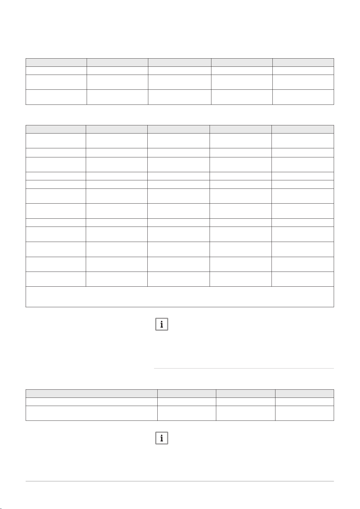
Tab.1 Composition of R-410A fluid
Name Proportion Number CE Number CAS
Difluoromethane R32 50% 200–839–4 75-10-5
Pentafluoroethane
R125
50% 206-557-8 354-33-6
The Global Warming Potential of R410A gas is 2088.
Page 11

Tab.2 Precautions for use
7611444 - v06 - 04032019 11
First aid If inhaled:
Evacuate the subject from the contaminated area and take him into
the open air.
If feeling unwell: call a doctor.
In the event of contact with the skin:
Treat frost injuries like burns. Rinse with copious amounts of tepid
water, do not remove clothing (risk of adhesion to the skin).
If skin burns appear, call a doctor immediately.
In the event of contact with the eyes:
Rinse immediately with water, holding the eyelids well apart (for at
least 15 minutes).
Consult an ophthalmologist immediately.
1 Safety
Fire prevention meas
ures
In the event of acci
dental spillage
Appropriate extinguishing agents: All extinguishing agents can be
used.
Inappropriate extinguishing agents: none to our knowledge. In the
event of fire nearby, use the appropriate extinguishing agents.
Specific hazards:
Rise in pressure: in the presence of air, an inflammable mixture
may form under certain temperature and pressure conditions.
Toxic and corrosive vapours may be released by the effect of the
heat.
Special intervention methods: cool the volumes exposed to heat with
water spray.
Protection of the firemen:
Full self-contained breathing apparatus.
Complete body protection.
Individual precautions:
Avoid contact with the skin and eyes.
Do not intervene without appropriate protective equipment.
Do not inhale the vapours.
Evacuate the hazardous area.
Stop the leakage.
Eradicate all sources of ignition.
Ventilate the spillage area mechanically.
Cleaning / decontamination: allow any residual product to evaporate.
In the event of contact with the eyes: Rinse immediately with water,
holding the eyelids well apart (for at least 15 minutes). Consult an oph
thalmologist immediately.
Handling Technical measures: ventilation
Precautions to be taken:
No smoking.
Prevent the build-up of electrostatic charges.
Work in a well ventilated place.
Page 12

1 Safety
12 7611444 - v06 - 04032019
Personal protection Respiratory protection:
If ventilation is insufficient: AX type cartridge mask.
In confined spaces: self-contained breathing apparatus.
Hand protection: protective gloves in leather or nitrile rubber.
Eye protection: safety glasses with side protection.
Skin protection: clothing made principally of cotton
Industrial hygiene: do not drink, eat or smoke at the place of work.
Considerations on dis
posal
Regulation
1.4
Liabilities
Important
Disposal must be done in compliance with prevailing lo
cal and national regulations.
Product waste: consult the manufacturer or the supplier for informa
tion on recovery or recycling.
Soiled packaging: reuse or recycle after decontamination. Destroy in
authorised installations.
Regulation (EU) No. 517/2014 of the European Parliament and of the
Council of 16 April 2014 on fluorinated greenhouse gases and re
pealing Regulation (EC) No. 842/2006.
ICPE Classified installations France No. 1185
1.4.1
To guarantee optimum operation of the system, you
must abide by the following instructions:
User's liability
Read and follow the instructions given in the manuals
provided with the appliance.
Call on a qualified professional to carry out installation
and initial commissioning.
Get your installer to explain your installation to you.
Have the required inspections and maintenance
carried out by a qualified installer.
Keep the instruction manuals in good condition close
to the appliance.
1.4.2
The installer is responsible for the installation and initial
commissioning of the appliance. The installer must
observe the following instructions:
Read and follow the instructions given in the manuals
provided with the appliance.
Install the appliance in compliance with prevailing
legislation and standards.
Carry out initial commissioning and any checks
necessary.
Explain the installation to the user.
Installer's liability
Page 13

1 Safety
7611444 - v06 - 04032019 13
If maintenance is necessary, warn the user of the
obligation to check the appliance and keep it in good
working order.
Give all the instruction manuals to the user.
1.4.3 Manufacturer's liability
Our products are manufactured in compliance with the
requirements of the various Directives applicable. They
are therefore delivered with the
documents necessary. In the interests of the quality of
our products, we strive constantly to improve them. We
therefore reserve the right to modify the specifications
given in this document.
Our liability as manufacturer may not be invoked in the
following cases:
Failure to abide by the instructions on installing and
maintaining the appliance.
Failure to abide by the instructions on using the
appliance.
Faulty or insufficient maintenance of the appliance.
marking and any
Page 14
MW-6000066-3
1 2
1
2
MW-6000691-1
2 About this manual
14 7611444 - v06 - 04032019
2 About this manual
2.1 General
This manual is intended for the user of a Alezio G hybrid hybrid heat
pump.
2.2
2.3
Additional documentation
Symbols used
These instructions contain information on the indoor module for the hybrid
heat pump (hydraulic module + boiler), and some information on the
outdoor unit.
For additional information on the outdoor unit, refer to the manual provided
with that unit.
2.3.1
This manual uses various danger levels to draw attention to special
instructions. We do this to improve user safety, to prevent problems and to
guarantee correct operation of the appliance.
Symbols used in the manual
Danger
Risk of dangerous situations that may result in serious personal
injury.
Danger of electric shock
Risk of electric shock.
Warning
Risk of dangerous situations that may result in minor personal
injury.
Fig.1 Symbols used on the appliance
Fig.2 Symbols used on the data plate
Caution
Risk of material damage.
Important
Please note: important information.
See
Reference to other manuals or pages in this manual.
2.3.2 Symbols used on the appliance
1 Alternating current
2 Protective earthing
1 Before installing and commissioning the appliance, carefully read
the instruction manuals provided
2 Dispose of used products in an appropriate recovery and recycling
structure
Page 15

3 Technical specifications
7611444 - v06 - 04032019 15
3.1 Homologations
3 Technical specifications
3.1.1 Directives
This product has been manufactured and put into circulation in
accordance with the requirements and standards of the following
European Directives:
Gas Appliances Regulation (EU) (2016/426)
Pressure Equipment Directive 2014/68/EU
Electromagnetic Compatibility Directive (2014/30/EU).
Low Voltage Directive (2014/35/EU).
Efficiency Directive (92/42/EEC)
European Ecodesign Directive (2009/125/EC)
EU Regulation (813/2013)
Energy Labelling Framework Regulation (EU) (2017/1369)
EU Regulation (811/2013)
Apart from the legal provisions and Directives, the additional Directives
described in these instructions must also be observed.
For all provisions and Directives referred to in these instructions, it is
agreed that all addenda or subsequent provisions will apply at the time of
installation.
3.1.2 Certifications
Tab.3 Certifications
CE identification number PIN 0063CM3019
Class NOx
(1)
Type of connection B23, B
(1) EN 15502–1
6
C
13(X)
C
(10)3(X)
23P
, C
33(X)
, C
, B
(12)3(X)
33
, C
43P
, C
53(X)
, C
63(X)
, C
Additional information
Heating boiler with efficiency class no. III in compliance with the
recommendations ATG B 84.
3.1.3 Unit categories
Tab.4 Unit categories
Country Category Gas type Connection pressure (mbar)
Austria II
Bulgaria II
Cyprus I
Czech Republic II
Algeria II
Estonia II
2H3B/P
2H3B/P
3B/P
2H3B/P
2H3P
2H3P
G20 (H gas)
G30/G31 (butane/propane)
G20 (H gas)
G30/G31 (butane/propane)
20
50
20
30
G30/G31 (butane/propane) 30-50
G20 (H gas)
G30/G31 (butane/propane)
20
30-50
G20 (H gas)
G31 (propane)
20
30
93(X)
,
Page 16

3 Technical specifications
16 7611444 - v06 - 04032019
Country Category Gas type Connection pressure (mbar)
Spain II
Finland II
France II
Greece II
Hungary II
Ireland II
Italy II
Lithuania II
Luxembourg II
Latvia I
Morocco II
Norway II
Poland II
Portugal II
Romania II
Serbia II
Slovenia II
Slovakia II
Tunisia II
Turkey II
Ukraine I
2H3B/P
2H3B/P
2Esi3B/P
2H3B/P
, I
2H3B/P
2H3B/P
2HM3B/P
2H3B/P
2H3P
2H
2H3P
2H3B/P
2ELwLs3B/P
2H3B/P
2H3P
2H3B/P
2H3B/P
2H3B/P
2H3P
2H3B/P
2H
2S
G20 (H gas)
G30/G31 (butane/propane)
G20 (H gas)
G30/G31 (butane/propane)
G20 (H gas)
G25 (L gas)
G30/G31 (butane/propane)
G20 (H gas)
G30/G31 (butane/propane)
G20 (H gas)
G30/G31 (butane/propane)
G25.1 (S gas)
G20 (H gas)
G30/G31 (butane/propane)
G20 (H gas)
G30/G31 (butane/propane)
G230 (Aria Propanata)
G20 (H gas)
G30/G31 (butane/propane)
G20 (H gas)
G31 (propane)
20
30-50
20
30
20
25
30-50
20
30-50
25
30-50
25
20
30
20
30
20
20
30
20
50
G20 (H gas) 20
G20 (H gas)
G30/G31 (butane/propane)
G20 (H gas)
G30/G31 (butane/propane)
G27 (Lw gas)
G2.350 (Ls gas)
G20 (H gas)
G30/G31 (butane/propane)
G20 (H gas)
G31 (propane)
G20 (H-gas)
G31 (Propane)
G20 (H gas)
G30/G31 (butane/propane)
G20 (H gas)
G30/G31 (butane/propane)
20
30
20
36
20
13
20
30-50
20
50
20
50
20
30
20
30-50
G20 (H gas)
G30/G31 (butane/propane)
20
30
G20 (H gas) 20
3.1.4 Factory test
Before leaving the factory, each indoor module is tested on the following
items:
Tightness of the heating circuit
Electrical safety
Tightness of the refrigerant circuit
Tightness of the domestic hot water circuit
Page 17

3 Technical specifications
7611444 - v06 - 04032019 17
3.2 Technical data
3.2.1 Boiler specifications
Tab.5 General
Alezio G hybrid 24/28 MI 34/39 MI
Nominal heat output (Pn)
Central heating operation (80 °C/60 °C)
Nominal heat output (Pn)
DHW operation
(1) Factory setting
Tab.6 Details of gas and flue gas
Alezio G hybrid 24/28 MI 34/39 MI
Gas consumption G20 (H gas) min–max
Gas consumption G25 (L gas) min–max
Gas consumption G31 (propane) min–max
NOx annual emissions G20 (H gas)
EN297: O2 = 0%
Central heating chimney efficiency (Hi)
(80/60°C) at 20 °C amb.
Central heating chimney losses (Hi)
(80/60°C) at 20 °C amb.
min–max
(1)
min–max
(1)
kW 5.5 - 23.8
19.8
kW 5.5 - 27.5
27.5
m3/h
m3/h
m3/h
0.59 - 2.98 0.83 - 4.13
0.69 - 3.47 0.96 - 4.80
0.29 - 1.15 0.41 - 1.47
7.7 - 34.7
29.8
7.7 - 37.8
37.8
ppm 45 56
% 97.2 97.0
% 2.8 3.0
Tab.7 Central heating circuit data
Alezio G hybrid 24/28 MI 34/39 MI
Water content l 1.6 1.7
Water operating pressure (MOP) max bar 3.0 3.0
Water temperature max °C 110.0 110.0
Operating temperature max °C 90.0 90.0
Tab.8 Domestic hot water circuit data
Alezio G hybrid 24/28 MI 34/39 MI
Specific hot water flow rate D (60 °C) l/min 7.5 10.5
Specific hot water flow rate D (40 °C) l/min 13 18.3
Flow rate threshold
(1)
min l/min 1.2 1.2
Operating pressure (Pmw) bar 8 8
(1) Minimum amount of water that comes out of the tap to make the boiler start.
Tab.9 Electrical data
Alezio G hybrid 24/28 MI 34/39 MI
Supply voltage VAC 230 230
Power consumption – full load
(1) Factory setting
max
(1)
W 90
78
127
106
Page 18

3 Technical specifications
18 7611444 - v06 - 04032019
Tab.10 Other data
Alezio G hybrid 24/28 MI 34/39 MI
Boiler weight (empty) kg 26 28.5
Average acoustic level
from the boiler
(1)
at a distance of one metre
Central heating
operation
dB(A) 38
42
42
46
DHW operation
(1) Maximum
3.2.2 Heat pump
Maximum operating pressure: 0.3 MPa (3 bar)
Tab.11 Conditions of use
AWHP 4.5 MR AWHP 6 MR-3 AWHP 8 MR-2
Limit water operating
temperatures in heating
mode
Outdoor air operating
temperature limits in
heating mode
Water operating temper
ature limits in cooling
mode
Outdoor air operating
temperature limits in
cooling mode
+18 °C/+55 °C +18 °C/+60 °C +18 °C/+60 °C
-15° C/+35 °C -15° C/+35 °C -20° C/+35 °C
+7°C / +25°C +7°C / +25°C +7°C / +25°C
+7 °C/ +46 °C +7 °C/ +46 °C +7 °C/ +46 °C
Tab.12 Heating mode: outside air temperature +7°C, water temperature at the outlet +35°C. Performances in accordance with
EN 14511-2.
Measurement type Unit AWHP 4.5 MR AWHP 6 MR-3 AWHP 8 MR-2
Heat output kW 4.6 5.82 7.90
Coefficient of perform
5.11 4.22 4.34
ance (COP)
Absorbed electrical
kWe 0.90 1.38 1.82
power
Nominal water flow rate
m3/hour
0.80 1.00 1.36
(ΔT = 5 K)
Tab.13 Heating mode: outside air temperature +2 °C, water temperature at the outlet +35 °C. Performances in accordance
with EN 14511-2.
Measurement type Unit AWHP 4.5 MR AWHP 6 MR-3 AWHP 8 MR-2
Heat output kW 3.47 3.74 6.80
Coefficient of perform
3.94 3.37 3.30
ance (COP)
Absorbed electrical
kWe 0.88 1.11 2.06
power
Page 19
3 Technical specifications
7611444 - v06 - 04032019 19
Tab.14 Cooling mode: outside air temperature +35 °C, water temperature at the outlet +18 °C. Performances in accordance
with EN 14511-2.
Measurement type Unit AWHP 4.5 MR AWHP 6 MR-3 AWHP 8 MR-2
Cooling output kW 3.80 4.69 7.90
Energy efficiency ratio
4.28 4.09 3.99
(EER)
Absorbed electrical
kWe 0.89 1.15 2.00
power
Tab.15 Common specifications
Measurement type Unit AWHP 4.5 MR AWHP 6 MR-3 AWHP 8 MR-2
Total dynamic head at
kPa 65 63 44
nominal flow rate
Nominal air flow rate
Power voltage of the
m3/hour
V~ 230 230 230
2680 2700 3300
outdoor unit
Start-up amperage A 5 5 5
Maximal amperage A 12 13 19
Acoustic power - In
(1)
side
Acoustic power - Out
(1)
side
dB(A) 41.6 41.6 41.6
dB(A) 61.0 64.8 66.7
Refrigerant fluid R410A kg 1.3 1.4 3.2
R410A refrigerant flu
(2)
id
.
Refrigerant connection
tCO2e 2.714 4.384 2.923
inch 1/4 - 1/2 1/4 - 1/2 3/8 - 5/8
(Liquid - Gas)
Max. pre-charged
m 7 10 10
length
Electrical protection
IP X2D IP X2D IP X2D
rating
(1) Noise radiated by the casing - Test run in accordance with the NF EN 12102 standard, temperature conditions: air 7 °C, water 55 °C
(45 °C for model AWHP 4.5 MR)
(2) Quantity of refrigerant fluid calculated in tonnes of CO2 equivalent
Important
The values in tonnes of CO2 equivalent are calculated using the
following formula: quantity (in kg) of refrigerant fluid x GWP /
1000.
The Global-Warming Potential (GWP) of R410A gas is 2088.
3.2.3 Weight
Tab.16 Hydraulic module
24/28 MI 34/39 MI
Weight of the hydraulic module (empty) kg 22 22
Total weight of the module with boiler, filled with wa
ter
kg 62 65
Important
For the weight of the boiler, refer to the Other Data table in the
Boiler technical characteristics section.
Page 20

3 Technical specifications
20 7611444 - v06 - 04032019
Tab.17 Outdoor unit
Weight (empty) Unit AWHP 4.5 MR AWHP 6 MR-3 AWHP 8 MR-2
Outdoor unit kg 54 42 75
3.2.4 Technical data - Low-temperature heat pump combination heaters
Tab.18 Technical parameters for heat pump combination heaters (parameters declared for medium-temperature application)
Product name AWHP 4.5MR–
EMC 24/28 MI
HYBRIDE
Air-to-water heat pump Yes Yes Yes
Water-to-water heat pump No No No
Brine-to-water heat pump No No No
Low-temperature heat pump No No No
Equipped with a supplementary heater Yes Yes Yes
Heat pump combination heater Yes Yes Yes
Rated heat output under average conditions
Rated heat output under colder conditions
Rated heat output under warmer conditions
(1)
(1)
Declared capacity for heating for part load at an
Prated
Prated
Prated
kW 8 8 11
kW 6 6 9
kW 4 5 6
(1)
indoor temperature of 20 °C and outdoor temper
ature
T
j
T
= -7°C
j
T
= +2 °C
j
T
= +7 °C
j
T
= +12 °C
j
T
= bivalent temperature
j
T
= operation limit temperature
j
Bivalent temperature
Degradation co-efficient
(2)
Seasonal space heating energy efficiency under
Pdh
Pdh
Pdh
Pdh
Pdh
Pdh
T
biv
Cdh
ƞ
s
kW 3.8 3.5 5.6
kW 4.3 4.5 6.1
kW 4.5 4.8 6.4
kW 5.5 5.2 6.5
kW 4.3 4.5 6.1
kW 3.9 3.6 5.6
°C 2 2 2
— 1.0 1.0 1.0
% 136 133 135
average conditions
Seasonal space heating energy efficiency under
ƞ
s
% 122 122 125
colder conditions
Seasonal space heating energy efficiency under
ƞ
s
% 172 166 169
warmer conditions
Declared coefficient of performance or primary
energy ratio for part load at an indoor tempera
ture of 20 °C and outdoor temperature
T
= -7°C
j
T
j
COPd
-
1.64 1.86 1.95
or
%
T
= +2 °C
j
COPd
-
3.46 3.40 3.49
or
%
T
= +7 °C
j
COPd
-
4.96 4.52 4.57
or
%
T
= +12 °C
j
COPd
-
7.35 6.70 6.33
or
%
AWHP 6MR3–
EMC 24/28 MI
HYBRIDE
AWHP 8MR–
EMC 24/28 MI
HYBRIDE
Page 21

3 Technical specifications
7611444 - v06 - 04032019 21
Product name AWHP 4.5MR–
EMC 24/28 MI
HYBRIDE
T
= bivalent temperature
j
COPd
-
3.46 3.40 3.49
AWHP 6MR3–
EMC 24/28 MI
HYBRIDE
AWHP 8MR–
EMC 24/28 MI
HYBRIDE
or
%
T
= operation limit temperature
j
COPd
-
1.84 1.52 1.63
or
%
Operation limit temperature for air-to-water
TOL
°C -10 -10 -10
heat pumps
Heating water operating limit temperature
WTOL
°C 80 80 80
Electrical power consumption
Off mode
Thermostat-off mode
Stand-by
Crankcase heater mode
P
P
P
P
OFF
TO
SB
CK
kW 0.009 0.009 0.009
kW 0.049 0.049 0.049
kW 0.012 0.018 0.018
kW 0.055 0.055 0.055
Supplementary heater
Rated heat output
(1)
Psup
kW 4.0 4.8 5.8
Type of energy input Gas Gas Gas
Other specifications
Capacity control Variable Variable Variable
Sound power level, indoors - outdoors
Annual energy consumption under average
conditions
Annual energy consumption under colder con
ditions
Annual energy consumption under warmer
conditions
Rated air flow rate, outdoors for air-to-water
L
Q
Q
Q
—
WA
HE
HE
HE
dB 42 – 61 41 – 63 41 – 64
kWh
GJ
kWh
GJ
kWh
GJ
m3/h
4045
6
4564
3
1299
0
4312
7
4236
3
1544
0
5859
8
6548
5
1904
0
2100 2100 3300
heat pumps
Declared load profile XL XL XL
Daily electricity consumption
Annual electricity consumption
Water heating energy efficiency
Daily fuel consumption
Annual fuel consumption
(1) The rated heat output
Psup
is equal to the supplementary capacity for heating
(2) If
Cdh
is not determined by measurement then the default degradation coefficient is
Prated
is equal to the design load for heating
Q
elec
AEC
ƞ
wh
Q
fuel
AFC
sup(Tj).
kWh 0.177 0.177 0.177
kWh 38 38 38
% 86.00 86.00 86.00
kWh 0.000 0.000 0.000
GJ 17 17 17
Pdesignh
, and the rated heat output of a supplementary heater
Cdh
= 0.9.
See
The back cover for contact details.
3.2.5 Hydraulic module circulating pump
Important
The benchmark for the most efficient circulating pumps is EEI ≤
0.20.
Page 22

4 Description of the product
22 7611444 - v06 - 04032019
4 Description of the product
4.1 General description
The hybrid heat pump comprises:
an indoor module for controlling the heating circuit water
a reversible outdoor unit for the production of energy in heating mode
and in cooling mode.
The indoor module comprises:
a hydraulic module, which integrates the functions for the heat pump's
indoor module
a wall-mounted condensing gas boiler and a connection kit, installed on
the front of the hydraulic module
The indoor module and the outdoor unit are connected by means of
refrigerant and electrical connections.
The system offers the following advantages:
An extremely compact solution which can be easily integrated into the
most confined areas of any residence.
A single control system to manage the entire system (heat pump and
boiler).
Choose the type of energy according to cost or CO2 emissions.
The heating circuit is housed in the insulated volume within the home.
Thanks to the DC inverter system, the hybrid heat pump modulates its
output to adapt to the needs of the residence.
The control system uses the outside sensor to adjust the temperature of
the heating circuit according to the outside temperature.
The outer casing of the hydraulic module is made of painted steel
sheeting.
4.2 Operating principle
Heat pumps in the Alezio G hybrid range extract heat from the air and
return it to the heating circuit via the refrigerant fluid. The efficiency of a
heat pump is expressed in the form of a coefficient of performance (COP),
defined as the ratio between the heat provided and the power consumed.
The heat pump comprises an evaporator, a compressor, a condenser and
an expansion valve. The indoor module includes the condenser. The other
components (evaporator, compressor and expansion valve) are located in
the outdoor unit.
1. The refrigerant fluid in the circuit is converted from the liquid state to
the gaseous state in the evaporator, making it possible to recover heat
from the air.
2. The compressor increases the fluid pressure, which thus increases
the temperature.
3. In the condenser, the fluid transfers the heat to the heating circuit
while converting to the liquid state.
4. The refrigerant passes through the thermostatic expansion valve and
returns to the initial state at low pressure and low temperature before
returning to the evaporator.
Page 23

Fig.3 General operating principle
5
2
1
3
6
4
7
8
MW-5000395-1
AD-0000918-01
3
5
6
7
9
8
13
12
14
15
11
10
1
2
4
7611444 - v06 - 04032019 23
4 Description of the product
1 Evaporator (fin battery in the outdoor unit)
2 Compressor
3 Condenser (plate exchanger in the indoor module)
4 Electronic expansion valve
4.3 Main components
Fig.4 Alezio G hybrid 24/28 MI - 34/39 MI
5 Electrical energy
6 Heating water
7 Energy flow
8 Heat recovered from the environment
4.3.1 Main boiler components
1
Flue gas outlet/air supply
2
Casing/air box
3
Flue gas measuring point
4
Ionisation/ignition electrode
5
Flue gas outlet
6
Gas/air system with fan, gas block and automatic burner unit
7
Air intake silencer
8
Plate heat exchanger (DHW)
9
Control panel
10
Siphon
11
Circulating pump
12
Three-way valve
13
Heat exchanger (CH)
14
Expansion vessel
15
Automatic air vent
Page 24

h
MW-2000124-4
8
1
5
6
7
4
3
2
11
12
13
14
15
16
9 10
MW-1000043-5
1 2 3 4
4 Description of the product
24 7611444 - v06 - 04032019
4.3.2 Main components of the hydraulic module
Fig.5 Main components of the hydraulic
module
1 Automatic air vent
2 Low-loss header
3 Electronic pressure gauge
4 Return from boiler back-up
5 Domestic hot water outlet (coming from the boiler)
6 Gas inlet (to the boiler)
7 Flow meter
8 EHC–04 PCB for controlling the heat pump hybrid system
9 Safety valve
10 Interface PCB for the outdoor unit
11 Plate heat exchanger
12 Flow to the heating back-up
13 Domestic cold water inlet (to the boiler)
14 Circulating pump
15 Refrigeration fluid connection (liquid)
16 Refrigeration fluid connection (gas)
4.4 Control panel description
Fig.6
4.4.1
1
2
3
4
Description of the keys
: back to the previous level without saving the modifications
made
: manual reset
: accessing the heating parameters
: lowering the value
: accessing the domestic hot water parameters
: raising the value
: MODE display
: accessing the menu selected or confirming the value
modification
Page 25

4.4.2 Description of the display
MW-1000669-2
MW-1000665-2
MW-5000012-3
MW-1000083-5
MW-5000037-4
MW-5000015-3
7611444 - v06 - 04032019 25
Hydraulic back-up
4 Description of the product
Fig.7
Fig.8
Fig.9
Hydraulic back-up in demand
Electrical back-up
Stage 1 of the electrical back-up
Stage 2 of the electrical back-up
Status of the Compressor
Steady symbol: compressing running
Operating modes
Fig.10
Fig.11
Fig.12
Steady symbol: heating function enabled
Flashing symbol: heating production running
Steady symbol: domestic hot water function enabled
Flashing symbol: domestic hot water production running
Heating or cooling function disabled
Domestic hot water function disabled
Hydraulic pressure in the system
The display alternates between the hydraulic pressure for the system and
the measured flow temperature.
Steady symbol: displayed when indicating the system's hydraulic
pressure value
Flashing symbol: pressure in the system too low
XXX Pressure value in the system (in bar) or flow temperature (in °C)
Cooling mode
Steady symbol: cooling mode on
Flashing symbol: cooling request pending
Page 26

MW-1000670-1
MW-1000754-2
...EHC / --04...
MW-1000687-1
...SCB / 04- / B...
MW-1000575-2
4 Description of the product
26 7611444 - v06 - 04032019
Menu display
Fig.13
Fig.14
Fig.15
Information menu: displays the measured values and the statuses
of the appliance
User menu: provides access to the User level setting parameters
Installer menu: provides access to the Installer level setting
parameters
Manual Forcing menu: the appliance runs at the set point
displayed, the pumps operate and the three-way valves are not
controlled.
Malfunction menu: the appliance has malfunctioned. This
information is signalled by an error code and a flashing display.
Sub-Menu COUNTERS
TIME PROG sub-menu: Timer programming dedicated to
heating and domestic hot water production
Sub-Menu CLOCK
PCB selection menu: access to information on the additional PCBs
connected
Display of PCB names
The name of the PCB for which the parameters are displayed is
scrolling across the screen on 3 characters.
Central unit EHC–04 PCB: direct circuit and domestic hot water
Fig.16
Fig.17
Additional SCB-04 PCB: second circuit
COUNTERS / TIME PROG / Sub-Menus CLOCK
COUNTERS sub-menu (CNT)
TIME PROG sub-menu: Timer programming dedicated to
heating and domestic hot water production (CIRC A, CIRC B,
ECS)
Timer program for Monday
Timer program for Tuesday
Timer program for Wednesday
Timer program for Thursday
Timer program for Friday
Timer program for Saturday
Timer program for Sunday
CLOCK sub-menu (CLK)
Page 27

Temperature sensors
MW-5000014-4
MW-5000038-4
7611444 - v06 - 04032019 27
4 Description of the product
Fig.18
Fig.19
Room temperature sensor connected:
fixed symbol for WINTER mode,
flashing symbol for SUMMER mode.
Outside temperature sensor connected:
fixed symbol for WINTER mode,
flashing symbol for SUMMER mode.
Other Information
Test Menu: forced operation in heating and cooling mode
Three-way valve connected
Three-way valve closed
Three-way valve open
Pump running
Page 28

MW-2000369-1
MW-1000576-2
MW-2000370-2
MW-2000371-1
5 Operation
28 7611444 - v06 - 04032019
5 Operation
5.1 Use of the control panel
Fig.20
5.1.1 Browsing in the menus
Press any key to turn on the backlight for the control panel screen.
If no key is pressed within 3 minutes, the control panel backlight will go
out.
Press the 2 right-hand keys together to access the different menus:
Tab.19 Menus available
Information menu
User menu
Installer menu
Manual Forcing menu
Malfunction menu
COUNTERS sub-menu
TIME PROG sub-menu
CLOCK sub-menu
PCB selection menu
Fig.21
Fig.22
Fig.23
Important
The icon is displayed only if an optional PCB has
been installed.
Important
The different menus are only accessible when the icons flash.
Press the key to:
access the next menu,
access the next sub-menu,
access the next parameter,
increase the value.
Press the key to:
access the previous menu,
access the previous sub-menu,
access the previous parameter
decrease the value.
Press the confirmation key to confirm:
a menu,
a sub-menu,
a parameter,
a value.
When the temperature is displayed, briefly pressing the back key h will
return to the time display.
5.2
Start-up
1. Switch on the outdoor unit and the indoor module.
2. The heat pump begins its start-up cycle.
If the start-up cycle runs normally, an automatic venting cycle is
initiated. Otherwise, an error message is displayed.
Page 29

5.3 Shutdown
MW-5000027-4
MW-5000133-3
MW-5000134-3
7611444 - v06 - 04032019 29
5 Operation
5.3.1 Switching off the heating
Important
Heating mode can be managed via the TIME PROG sub-menu
dedicated to timer programming.
Important
If the heating function is shut off, then the cooling will also be shut
off.
Fig.24
Fig.25
Fig.26
1. Go to stop mode by pressing the key.
2. Select the heating mode by pressing the key.
3. Confirm by pressing the key.
4. Select the heating shut-down pressing the key.
The screen displays: .
The frost protection function continues to run.
The heating and cooling have been shut down.
Important
Press the key to restart the appliance: the screen will
display .
5. Confirm by pressing the key.
6. Go back to the main display by pressing the h key.
Important
The display disappears after a few seconds of inactivity.
Page 30

MW-5000135-3
MW-5000136-3
MW-5000028-4
5 Operation
30 7611444 - v06 - 04032019
5.3.2 Stopping domestic hot water production
Important
Domestic hot water production can be managed via the TIME
PROG sub-menu dedicated to timer programming.
Fig.27
Fig.28
Fig.29
1. Go to stop mode by pressing the key.
2. Select domestic hot water production mode pressing the key.
3. Confirm by pressing the key.
4. Select domestic hot water production shut-down by pressing the
key.
The screen displays: .
The frost protection function continues to run.
Production of domestic hot water has been shut down.
Important
Press the key to restart the appliance: the screen will
display .
5. Confirm by pressing the key.
6. Go back to the main display by pressing the h key.
Important
The display disappears after a few seconds of inactivity.
5.3.3 Shutting down the cooling function
Important
If the heating function is shut off, then the cooling will also be shut
off.
1. Access the menu.
2. Confirm access by pressing the key.
3. Select CIRCA or CIRCB by pressing the or key.
4. Confirm the selection by pressing the key.
5. Select TP.C by pressing the or keys.
6. Confirm the selection by pressing the key.
7. Modify the timer program to stop cooling.
5.4
Frost Protection
If the temperature of the heating water in the heat pump falls too much,
the integrated protection device switches itself on. This device functions as
follows:
Page 31

5 Operation
7611444 - v06 - 04032019 31
If the water temperature is lower than 5°C, the circulating pump starts
up.
If the water temperature is lower than 3°C, the back-up starts up.
If the water temperature is higher than 10°C, the back-up shuts down
and the circulating pump continues to run for a short time.
The radiator valves in rooms where there is a risk of frost must be fully
open.
Page 32

1
2
MW-2000435-1
3
2
MW-5000008-2
MW-5000040-6
6 Settings
32 7611444 - v06 - 04032019
6 Settings
6.1 Modifying the User parameters
Caution
Altering the factory settings may impair operation of the appliance.
Fig.30
Fig.31
6.2 User menu
Fig.32
1 Sub-menu available
2 Name of the PCB or circuit
1. Go to the User menu.
2. Select the desired sub-menu by pressing the or key.
3. Confirm the selection by pressing the key.
4. Select the required parameter by pressing the or keys to scroll
through the list of adjustable parameters.
5. Confirm the selection by pressing the key.
6. Modify the value of the parameter using the or keys.
7. Confirm the new value of the parameter by pressing the key.
8. Go back to the main display by pressing the h key.
3 Setting parameters
Tab.20
Sub-menu Description Name of the PCB or circuit
CIRCA Main heating circuit EHC–04
CIRCB Additional heating circuit B SCB-04
ECS Domestic hot water circuit EHC–04
EHC–04 EHC–04 central unit PCB EHC–04
SCB-04 Additional PCB for circuit B SCB-04
HMI HMI control panel HMI
List of User sub-menus
6.2.1 User \CIRCA and CIRCB menu
CP : Circuits Parameters = Heating circuit parameters
Tab.21
Parameter Description Factory setting
CIRCA
CP010 Zone flow temperature setpoint, used when the zone is set to a fixed
flow setpoint.
CP080 Room setpoint temperature of the user zone activity
Can be set from 5 °C to 30 °C
CP081 Room setpoint temperature of the user zone activity in activity zone
2
Can be set from 5 °C to 30 °C
not available 50
16 16
20 20
Factory setting
CIRCB
Page 33

6 Settings
7611444 - v06 - 04032019 33
Parameter Description Factory setting
CIRCA
CP082 Room setpoint temperature of the user zone activity in activity zone
6 6
3
Can be set from 5 °C to 30 °C
CP083 Room setpoint temperature of the user zone activity in activity zone
21 21
4
Can be set from 5 °C to 30 °C
CP084 Room setpoint temperature of the user zone activity in activity zone
22 22
5
Can be set from 5 °C to 30 °C
CP085 Room setpoint temperature of the user zone activity in activity zone
23 20
6
Can be set from 5 °C to 30 °C
CP140 Setpoint of the room cooling temperature of the zone: cooling activity
30 30
zone 1
Can be set from 20 °C to 30 °C
CP141 Setpoint of the room cooling temperature of the zone: cooling activity
25 25
zone 2
Can be set from 20 °C to 30 °C
CP142 Setpoint of the room cooling temperature of the zone: cooling activity
25 25
zone 3
Can be set from 20 °C to 30 °C
CP143 Setpoint of the room cooling temperature of the zone: cooling activity
25 25
zone 4
Can be set from 20 °C to 30 °C
CP144 Setpoint of the room cooling temperature of the zone: cooling activity
25 25
zone 5
Can be set from 20 °C to 30 °C
CP145 Setpoint of the room cooling temperature of the zone: cooling activity
25 25
zone 6
Can be set from 20 °C to 30 °C
CP200 Manually setting the room temperature setpoint of the zone
20 20
Can be set from 5 °C to 30 °C
CP320 Operating mode of the zone
0 0
0 = timer programming
1 = manual mode
2 = frost protection mode
CP350 Comfort Domestic Hot Water Temperature Setpoint of zone
not available 55
Can be set from 40 °C to 80 °C
CP360 Reduced Domestic Hot Water Temperature Setpoint of zone
not available 10
Can be set from 10 °C to 60 °C
CP510 Temporary room setpoint per zone
20 20
Can be set from 5 °C to 30 °C
CP540 Setpoint of swimming pool when Zone is configured on Swimming
not available 20
Pool
Can be set from 0 °C to 39 °C
CP550 Fire Place mode is active
0 0
0 = off
1 = on
Factory setting
CIRCB
Page 34

6 Settings
34 7611444 - v06 - 04032019
Parameter Description Factory setting
CIRCA
CP570 Time Program of the zone selected by the user
0 = programme 1
1 = programme 2
2 = programme 3
CP660 Choice icon to display this zone
0 =None
1 =All
2 =Bedroom
3 =Livingroom
4 =Study
5 =Outdoor
6 =Kitchen
7 =Basement
8 =Swimming Pool
0 0
0 3
Factory setting
CIRCB
6.2.2 User \DHW menu
DP : Direct Hot Water Parameters = Domestic hot water tank parameters
Tab.22
Parameter Description Factory setting
DP060 Time program selected for DHW.
0 =Schedule 1
1 =Schedule 2
2 =Schedule 3
3 =Cooling
DP070 Comfort temperature setpoint from the Domestic Hot Water tank
Can be set from 40 °C to 65 °C
DP080 Reduced temperature setpoint from the Domestic Hot Water tank
Can be set from 10 °C to 60 °C
DP200 DHW primary mode current working setting
0 =Scheduling
1 =Manual
2 =Antifrost
3 =Temporary
DP337 Holiday temperature setpoint from the Domestic Hot Water tank
Can be set from 10 °C to 60 °C
0
54
10
1
10 °C
6.2.3 User \EHC–04 menu
AP : Appliance Parameters = Appliance parameters
Tab.23
Parameter Description Factory setting
AP015 Force manually the heat pump in cooling mode
0 =No
1 =Yes
AP016 Enable central heating heat demand processing
0= off (no heating or cooling)
1 = on
AP017 Enable domestic hot water heat demand processing
0 = off
1 = on
0
1
1
Page 35

6 Settings
7611444 - v06 - 04032019 35
Parameter Description Factory setting
AP073 Outdoor temperature: upper limit for heating
22
SUMMER / WINTER set point switch:
Can be set from 15 °C to 30.5 °C
AP074 The heating is stopped. Hot water is maintained. Force Summer Mode
0
SUMMER override:
0 = off
1 = on
AP082 Automatic change between summer and winter time
0
0 = Off
1 = On
HP : Heat-pump Parameters = Heat pump parameters
Tab.24
Parameter Description Factory setting
HP062 Energy cost in Hybrid electricity cost in high tarif
0.13 €/kWh
Can be set from 0.01 to 2.50 €/kWh
HP063 Energy cost in Hybrid electricity cost in low tarif
0.09 €/kWh
Can be set from 0.01 to 2.50 €/kWh
HP064 Cost of fossil energy (oil or gas) - price per litre or per m3
Cost of fossil energy (oil or gas) - price per litre or per m
3
0.90 €/kWh
Can be set from 0.01 to 2.50 €/kWh
6.2.4 User \HMI menu
Tab.25 AP : Appliance Parameters = Appliance parameters
Parameter Description Factory setting
AP067 BKL backlighting
0 = off after 3 minutes of inactivity on the control panel
1 = on
AP103 Setting the LANGUAGE:
0 = no language
FR = French
NL = Dutch
EN = English
DE = German
ES = Spanish
IT = Italian
PL = Polish
PT = Portuguese
AP104 Setting the CONTRAST:
Can be set from 0 to 3
AP105 Selecting the UNIT:
0 = °C
1 = °F
AP082 Changing the DLS summer/winter timer:
0 = off
1 = on
0
FR
3
0
0
6.2.5 HP parameters in the User menu
HP : Heat-pump Parameters = Heat pump parameters
Page 36

6 Settings
36 7611444 - v06 - 04032019
Tab.26
Parameter Description Factory setting
EHC–04
HP062 Hybrid electricity cost in high tarif
Can be set from 0.01 to 2.50 €/kWh
HP063 Hybrid electricity cost in low tarif
Can be set from 0.01 to 2.50 €/kWh
HP064 Cost of fossil energy (oil or gas) - price per litre or per m3
Cost of fossil energy (oil or gas) - price per litre or per m
Can be set from 0.01 to 2.50 €/kWh
3
0.13 €/kWh
0.09 €/kWh
0.90 €/kWh
6.3
Tab.27
Sub-menu Description
CNT COUNTERS
CIRCA Timer programming for the main heating circuit
CIRCB Timer programming for the additional heating circuit B
DHW Timer programming for the domestic hot water circuit
CLK Setting the clock and the date
COUNTERS /TIME PROG / CLOCK menus
List of sub-menus
6.3.1 COUNTERS, TIME PROG, CLOCK \CNT menus
Tab.28 Choosing the menu
Counters Selection
Circuit A counters Choose the EHC–04 menu
Circuit B counters Choose the SCB-04 menu
Counters connected to the opera
tion of the heat pump
Choose the EHC–04 menu
Tab.29 Available counters
Parameter Description Unit EHC–04 SCB-04
AC001 Number of hours that the appliance has been on
mains power
AC005 Energy consumed for central heating kWh X
AC006 Enegy consumed for domestic hot water Wh X
AC007 Energy consumed for cooling Wh X
AC008 Energy delivered for central heating kWh X
AC009 Energy delivered for domestic hot water kWh X
AC010 Energy delivered for cooling kWh X
AC013 Seasonal COP X
AC026 Counter that shows the number of pump running
hours
AC027 Counter that shows the number of pump starts - X
AC028 Total working time of the first stage of backup hours X
AC029 Total working time of the second stage of backup hours X
AC030 Total startings of the first stage of backup - X
AC031 Total startings of the second stage of backup - X
DC002 Numbers of Domestic Hot Water diverting valve
cycles
hours X X
hours X
- X
Page 37

6 Settings
7611444 - v06 - 04032019 37
Parameter Description Unit EHC–04 SCB-04
DC003 Number of hours during which the diverting valve
is in DHW position
DC004 Number of compressor start-ups during domestic
hot water production
DC005 Number of compressor start-ups X
PC003 Number of compressor operating hours hours X
CODE Enter the installer code to access the following pa
rameters.
AC002 Number of hours that the appliance has been
producing energy since last service
AC003 Number of hours since the previous servicing of
the appliance
AC004 Number of generator startings since the previous
servicing.
AC013 Seasonal coefficient of performance X
SERVICE Resetting the maintenance service
CLR: the AC002, AC003, and AC004 counters are
reset to zero.
hours X
X
X
hours X
hours X
X
X
6.3.2
COUNTERS, TIME PROG, CLOCK \CIRCA, CIRCB
and DHW menus
Tab.30
Menu Description
CIRCA TP.H: Timer programming for heating
06:00 - 23:00 ON
23:00 - 06:00 OFF
TP.C: Timer programming for cooling
14:00 - 23:00 ON
23:00 - 14:00 OFF
CIRCB TP.H: Timer programming for heating
06:00 - 23:00 ON
23:00 - 06:00 OFF
TP.C: Timer programming for cooling
14:00 - 23:00 ON
23:00 - 14:00 OFF
DHW Timer programming for domestic hot water
06:00 - 23:00 ON
23:00 - 06:00 OFF
6.3.3 COUNTERS, TIME PROG, CLOCK \CLK menus
Tab.31
CLK parameter Unit HMI
HOURS Can be set from 0 to 23 available
MINUTE Can be set from 0 to 59 available
DATE Can be set from 1 to 31 available
MONTH Can be set from 1 to 12 available
YEAR Can be set from 2000 to 2100 available
Page 38

MW-5000144-3
MW-3000249-4
MW-6000254-2
6 Settings
38 7611444 - v06 - 04032019
6.4 Setting the parameters
6.4.1 Setting the room temperature set point in comfort mode
Important
The room temperature set point can be managed via the TIME
PROG sub-menu dedicated to timer programming.
Important
To set the room set point temperature in reduced mode, it is
necessary to set the CP080 parameter available in the User
menu.
When the setting is made in a reduced mode range, this setting
shortcut is used only to set the set point temperature in comfort
mode corresponding to the CP081.
Fig.33
Fig.34
Fig.35
1. Access the heating parameters by pressing the key twice.
2. Display the parameters for the required circuit by pressing the or
key.
3. Confirm by pressing the key.
The name of the circuit and the heating water temperature set point
are displayed alternately.
4. Access setting of the heating water temperature set point by pressing
the key.
5. Set the heating water temperature set point by pressing the or
key.
6. Confirm the new temperature set point by pressing the key.
Important
Press the h key to cancel all inputs.
6.4.2 Setting the domestic hot water temperature
Important
Domestic hot water production can be managed via the TIME
PROG sub-menu dedicated to timer programming.
1. Access the domestic hot water production parameters by pressing the
key.
2. Modify the domestic hot water temperature set point by pressing the
or key.
Important
Press the h key to cancel all input.
3. Confirm the new temperature set point by pressing the key.
Go back to the main display by pressing the h key.
6.4.3 Activating Forcing of the cooling function
The cooling function can be managed via the PROG COOL sub-menu
dedicated to timer programming.
The set point flow temperature for cooling mode corresponds to the
CP270 parameter for underfloor heating and CP280 for a convection fan.
The CP270 and CP280 parameters can be accessed by the Installer.
Page 39

MW-5000401-2
MW-5000402-2
MW-5000403-2
MW-5000404-2
MW-5000010-4
6 Settings
7611444 - v06 - 04032019 39
Important
The heat pump switches to cooling automatically when the
outdoor temperature is +2 °C greater than the summer/winter
switching set point temperature (22 °C). The forced cooling
function is used to have cooling regardless of the outdoor
temperature.
Fig.36
Fig.37
Fig.38
1. Access Forcing of the cooling function by pressing the key.
Important
Forcing of the cooling function is possible only if the Installer
enabled the cooling function during Installation.
2. Access Forcing of the cooling function by pressing the key.
3. Activate Forcing of the cooling function by pressing the key.
Fig.39
Fig.40
4. Confirm Forcing of the cooling function by pressing the key.
5. Go back to the main display by pressing the h key.
6.4.4
Activating Manual Forcing for heating
The Manual Forcing menu is only used with the heating mode.
1. Access the Manual Forcing menu.
Page 40

MW-5000042-4
MW-5000044-4
MW-5000139-4
MW-5000486-1
MW-1000594-3
6 Settings
40 7611444 - v06 - 04032019
Fig.41
Fig.42
Fig.43
2. Set the value of the heating water temperature set point by pressing
the or key.
3. Confirm the new value of the heating water temperature set point by
pressing the
key.
4. Go back to the main display by pressing the h key.
Important
To force domestic hot water production, select the DP200
parameter available in the User menu.
6.4.5 Setting the timer programming
1. Access the COUNTERS/ TIME PROG / CLOCK menus.
Important
When using a programmable room thermostat, this menu is not
displayed.
2. Select the desired circuit by pressing the or key.
Fig.44
Fig.45
3. Confirm the selection by pressing the key. Select the timer
programming for the heating or the timer programming for the
cooling by pressing the or key.
4. Confirm the selection by pressing the key.
The icons dedicated to the days of the week all flash at the same
time: .
5. Select the desired day number by pressing the or key until the
icon dedicated to the desired day flashes.
Day selected Description
, , , , , , every day of the week
Monday
Tuesday
Wednesday
Thursday
Friday
Saturday
Sunday
Important
The key is used to move to the right.
The key is used to move to the left.
6. Confirm the selection by pressing the key.
Page 41

MW-5000142-2
MW-5000143-3
6 Settings
7611444 - v06 - 04032019 41
Fig.46
Fig.47
7. Set the start time for the period by pressing the or key.
Confirm the selection by pressing the key.
8.
9. Select the status that corresponds to the period by pressing
the or key.
Status
to for periods
Description
to
comfort mode
reduced mode
10. Confirm the selection by pressing the key.
11. Repeat steps 8 to 11 to define the comfort periods to and
the associated status to .
Important
No setting: 10 minutes
The setting determines the end.
Times
06:00-22:00 06:00 22:00
06:00-08:00
06:00 08:00 11:30 13:30
11:30-13:30
06:00-08:00
06:00 08:00 11:30 14:00 17:30 22:00
11:30-14:00
17:30-22:00
12. Go back to the main display by pressing the h key.
Example:
Page 42

7 Reading out measured values
42 7611444 - v06 - 04032019
7 Reading out measured values
The measured values are available in the Information menu of the
different PCBs.
Certain parameters are displayed:
according to certain system configurations,
according to the options, circuits or sensors actually connected.
Tab.32 Choosing the menu
Counters Selection
Measured values on circuit A Choose the EHC–04 menu
Measured values on circuit B Choose the SCB-04 menu
Measured values connected to the
operation of the heat pump
Tab.33 Values available (X) in the sub-menus EHC–04, SCB-04
Parameter Description Unit EHC–04 SCB-04
AM002 "Silent mode" status X
AM010 The current pump speed % X
AM012 Current main status of the appliance.
Choose the EHC–04 menu
X X
See
Control system sequence chapter
AM014 Current sub status of the appliance.
See
Control system sequence chapter
AM015 Is the pump running? X
AM016 Flow temperature of appliance. °C X
AM019 Water pressure of the primary circuit. bar X
AM027 Instantaneous outside temperature °C X X
AM040 Temperature used for hot water control algorithms. °C X
AM056 Wate flow rate in the system l/min X
AM091 Seasonal mode active (summer / winter)
0: Winter
1: Frost protection
2: Summer neutral band
3: Summer
AM101 Internal system flow temperature setpoint X
CM030 Measure of the room temperature of the zone °C X X
CM040 Measure Zone Flow Temperature or DHW
temperature
CM060 Current Pump speed of zone % X
CM120 Zone Current Mode:
0 = Scheduling
1 = Manual
2 =Antifrost
3 =Temporary
CM130 Current activity of the zone:
0 = Anti frost
1 =Reduced
2 =Comfort
3 =Anti legionella
CM190 Wished room temperature setpoint of the zone °C X X
CM210 Current outdoor temperature of the zone °C X X
°C X
X X
X X
X X
X X
Page 43

7 Reading out measured values
7611444 - v06 - 04032019 43
Parameter Description Unit EHC–04 SCB-04
DM001 Domestic Hot Water tank temperature (bottom sensor) °C X
DM006 Domestic Hot Water tank temperature (top sensor) X
DM009 Automatic/derogation status of Domestic Hot Water
mode:
0 =Scheduling
1 = Manual
2 =Antifrost
3 =Temporary
DM029 Domestic Hot Water temperature setpoint °C X
HM001 Heat pump flow temperature after condenser °C X
HM002 Heat pump return temperature after condenser. °C X
HM033 Flow temperature setpoint in cooling mode °C X
HM046 Heat pump 5V signal output setpoint V X
PM002 External winning Central Heating setpoint °C X
Fxx.xx Software version for the selected PCB X X
Pxx.xx Parameter version for the selected PCB X X
Tab.34 Values available (X) in the HMI sub-menu
Parameter Description EHC–04 SCB-04
Fxx.xx HMI software version X X
Pxx.xx HMI parameter version X X
°C X
7.1 Reading out hybrid measured values
The hybrid measured values are available in the Information menu of
the EHC–04 PCB.
Tab.35 Values available (X) in the EHC-04 sub-menus
Parameter Description Unit
HM034 Heat pump PCU backup flow temperature °C
HM035 Heat pump PCU backup return temperature °C
HM036 Heat pump PCU backup domestical hot water temperature °C
HM037 Heat pump PCU back up Internal Setpoint °C
HM038 Heat pump PCU back up status
HM039 Heat Pump PCU back up Sub Status
HM040 Heat Pump PCU back up Output power %
HM041 Heat pump PCU back up locking code
HM042 Heat pump PCU back up blocking code
Page 44

7 Reading out measured values
44 7611444 - v06 - 04032019
7.2 Control system sequence
Tab.36 List of statuses and sub-statuses
Status Appliance: AM012 parameter Appliance sub status: AM014 parameter
0 00= total system shut-down
1= heating / cooling / domestic hot water de
mand
3= operating in heating mode 30= normal operation
Heat Demand
00 = off
The set point is reached. The compressor can start up whenever necessary.
01= anti-short cycle
The heating set point has been reached. The compressor is not authorised to
restart.
02= reversal valve switch to heating position
03= power supply to the hybrid pump
04= pending start-up conditions on the heat pump and the back-ups
62= three-way valve switch to domestic hot water position
The compressor or the back-ups are running.
31= internal set point limited
If the heating set point on the heat pump differs from the system set point.
60= pump post-operation
Heat pump and back-up shut-down, system pump operation.
65= compressor bypass
The back-ups are operating.
66= the temperature exceeds the compressor's maximum operating tempera
ture
The compressor has stopped. The back-ups are operating.
67= the outside temperature is lower than the compressor's maximum operat
ing temperature
The compressor has stopped. The back-ups are operating.
68= the hybrid function requests compressor shut-down
The compressor has stopped. The back-ups are operating.
69= defrosting running
The compressor is running.
70= defrosting conditions not met
The compressor has stopped. The back-ups are operating.
71= defrosting running
The compressor and the back-ups are running.
88 = BL-Back-up limited
Back-ups shed
89 = BL-Heat pump limited
Compressor shed
90 = BL-Heat pump & back-up limited
Compressor and back-ups shed
91 = BL-Off-peak rate
Off-peak cost
92 = PV-with Heat pump
Photovoltaic powered by compressor only
93 = PV-with Heat pump & back-up
Photovoltaic powered by compressor and back-ups
94 = BL-Smart Grid
Smart Grid Ready function
Page 45

Status Appliance: AM012 parameter Appliance sub status: AM014 parameter
7611444 - v06 - 04032019 45
4= operating in domestic hot water mode 30= normal operation
The compressor or the back-ups are running.
31= internal set point limited
If the heating set point on the heat pump differs from the system set point.
60= pump post-operation
Heat pump and back-up shut-down, system pump operation.
65= compressor bypass
The back-ups are operating.
66= the temperature exceeds the compressor's maximum operating tempera
ture
The compressor has stopped. The back-ups are operating.
67= the outside temperature is lower than the compressor's maximum operat
ing temperature
The compressor has stopped. The back-ups are operating.
68= the hybrid function requests compressor shut-down
The compressor has stopped. The back-ups are operating.
69= defrosting running
The compressor is running.
70= defrosting conditions not met
The compressor has stopped. The back-ups are operating.
71= defrosting running
The compressor and the back-ups are running.
88 = BL-Back-up limited
Back-ups shed
89 = BL-Heat pump limited
Compressor shed
90 = BL-Heat pump & back-up limited
Compressor and back-ups shed
91 = BL-Off-peak rate
Off-peak cost
92 = PV-with Heat pump
Photovoltaic powered by compressor only
93 = PV-with Heat pump & back-up
Photovoltaic powered by compressor and back-ups
94 = BL-Smart Grid
Smart Grid Ready function
6 Pump Post Run
60= pump post-operation
Heat pump and back-up shut-down, system pump post-operation.
7 Cooling Active
30= normal operation
Cooling is active.
75= compressor shut-down owing to the condensation detector
78= correction of the temperature set point
Increase in the cooling set point owing to the condensation detector.
82= temperature lower than the minimum cooling temperature
Compressor shut-down.
7 Reading out measured values
Page 46

7 Reading out measured values
46 7611444 - v06 - 04032019
Status Appliance: AM012 parameter Appliance sub status: AM014 parameter
8= controlled compressor shut-down Controlled Stop
00= off: the heating or cooling set point has been reached
01= anti-short cycle
The heating set point has been reached. The compressor is not authorised to
restart.
60= pump post-operation
Heat pump and back-up shut-down, system pump post-operation.
67= the outside temperature is lower than the compressor's maximum operat
ing temperature
The compressor has stopped. The back-ups are operating.
68= the hybrid function requests compressor shut-down
The compressor has stopped. The back-ups are operating.
75= compressor shut-down owing to the condensation detector
76= compressor shut-down owing to the flow rate
79= compressor and back-up bypass in heating / domestic hot water mode
80= compressor and back-up bypass in cooling mode
82= temperature lower than the minimum cooling temperature
Compressor shut-down.
9 Blocking Mode
30= normal operation.
The compressor or the back-ups are running.
31= internal set point limited
If the heating set point on the heat pump differs from the system set point.
60= pump post-operation
Heat pump and back-up shut-down, system pump running.
65= compressor bypass
The back-ups are operating.
66= the temperature exceeds the compressor's maximum operating tempera
ture
The compressor has stopped. The back-ups are operating.
67= the outside temperature is lower than the compressor's maximum operat
ing temperature
The compressor has stopped. The back-ups are operating.
68= the hybrid function requests compressor shut-down
The compressor has stopped. The back-ups are operating.
69= defrosting running
The compressor is running.
70= defrosting conditions not met
The compressor has stopped. The back-ups are operating.
71= defrosting running.
The compressor and the back-ups are running.
88 = BL-Back-up limited
Back-ups shed
89 = BL-Heat pump limited
Compressor shed
90 = BL-Heat pump & back-up limited
Compressor and back-ups shed
91 = BL-Off-peak rate
Off-peak cost
92 = PV-with Heat pump
Photovoltaic powered by compressor only
93 = PV-with Heat pump & back-up
Photovoltaic powered by compressor and back-ups
94 = BL-Smart Grid
Smart Grid Ready function
10 Locking Mode
11 Load test min
Page 47

Status Appliance: AM012 parameter Appliance sub status: AM014 parameter
7611444 - v06 - 04032019 47
12 Load test CH max
30= normal operation. The compressor or the back-ups are running.
31= internal set point limited
If the heating set point on the heat pump differs from the system set point.
60= pump post-operation
Heat pump and back-up shut-down, system pump post-operation.
65= compressor bypass and back-ups running
66= the temperature exceeds the compressor's maximum operating tempera
ture
The compressor has stopped. The back-ups are operating.
67= the outside temperature is lower than the compressor's maximum operat
ing temperature
The compressor has stopped. The back-ups are operating.
68= the hybrid function requests compressor shut-down
The compressor has stopped. The back-ups are operating.
69= defrosting running
The compressor is running.
70= defrosting conditions not provided
The compressor has stopped. The back-ups are operating.
71= defrosting running.
The compressor and the back-ups are running.
7 Reading out measured values
Page 48

7 Reading out measured values
48 7611444 - v06 - 04032019
Status Appliance: AM012 parameter Appliance sub status: AM014 parameter
16 Frost protection
30= normal operation
The compressor or the back-ups are running.
31= internal set point limited
If the heating set point on the heat pump differs from the system set point.
60= pump post-operation
Heat pump and back-up shut-down, system pump post-operation.
65= compressor bypass and back-ups running
66= the temperature exceeds the compressor's maximum operating tempera
ture
The compressor has stopped. The back-ups are operating.
67= the outside temperature is lower than the compressor's maximum operat
ing temperature
The compressor has stopped. The back-ups are operating.
68= the hybrid function requests compressor shut-down
The compressor has stopped. The back-ups are operating.
69= defrosting running
The compressor is running.
70= defrosting conditions not met
The compressor has stopped. The back-ups are operating.
71= defrosting running.
The compressor and the back-ups are running.
17 DeAiration
30= normal operation
The compressor or the back-ups are running.
31= internal set point limited
If the heating set point on the heat pump differs from the system set point.
60= pump post-operation
Heat pump and back-up shut-down.
65= compressor bypass and back-ups running
66= the temperature exceeds the compressor's maximum operating tempera
ture
The compressor has stopped. The back-ups are operating.
67= the outside temperature is lower than the compressor's maximum operat
ing temperature
The compressor has stopped. The back-ups are operating.
68= the hybrid function requests compressor shut-down
The compressor has stopped. The back-ups are operating.
69= defrosting running
The compressor is running.
70= defrosting conditions not met
The compressor has stopped. The back-ups are operating.
71= defrosting running.
The compressor and the back-ups are running.
Page 49

8 Maintenance
7611444 - v06 - 04032019 49
8.1 General
8 Maintenance
Maintenance operations are important for the following reasons:
To guarantee optimum performance.
To extend the life of the equipment.
To provide an installation which offers the user optimum comfort over
time.
Caution
Only qualified professionals are authorised to carry out
maintenance work on the heat pump and the heating system.
Danger of electric shock
Before any work, switch off the mains electricity to the heat pump
and the hydraulic back-up if present.
Caution
Before working on the refrigeration circuit, switch off the appliance
and wait a few minutes. Certain items of equipment such as the
compressor and the pipes can reach temperatures in excess of
100°C and high pressures, which may cause serious injuries.
Caution
Do not drain the installation, except in cases of absolute
necessity. E.g.: several months' absence with the risk of
temperatures in the building falling below freezing.
8.1.1
Troubleshooting
Caution
All work on the refrigeration circuit must be done by a qualified
professional, according to prevailing codes of practice and safety
in the profession (recovery of the refrigerant, brazing under
nitrogen). All brazing work must be done by qualified welders.
Caution
This appliance is fitted with pressurised equipment, including the
refrigeration pipes.
Caution
Use only original parts to replace a defective refrigeration
component.
Caution
Use only dehydrated nitrogen for detecting leaks or for
pressurised tests.
Caution
Only a qualified professional is authorised to set, correct or
replace the safety devices.
8.2
Standard inspection and maintenance operations
An annual inspection with tightness check is obligatory. Schedule a
service by a qualified professional at a cold time of the year to check the
following points:
1. Operation of the installation.
2. Thermal output, by measuring the difference in temperature between
heating flow and return.
3. The setting for the safety thermostats.
Page 50

AD-3000484-B
87
A
C
B
6
5
4
3
2
1
2
3
4
1
11
8 Maintenance
50 7611444 - v06 - 04032019
8.2.1 Checking the water pressure
1. Check the water pressure.
The water pressure must be at least 0.8 bar.
2. If the water pressure is lower than 0.8 bar, top up the central heating
system.
8.3
Cleaning the casing
1. Clean the outside of the appliance using a damp cloth and a mild
detergent.
8.4 Venting the system
Fig.48 Venting the system
Any air in the boiler, the pipes or the valves must be removed in order to
prevent unwanted noises that may occur during heating or when tapping
water. Proceed as follows:
1. Open the valves of all the radiators connected to the system.
2. Set the room thermostat to the highest possible temperature.
3. Wait until the radiators are warm.
4. Ensure that the boiler is disconnected from the power supply.
5. Wait approximately ten minutes, until the radiators feel cold.
6. Vent the radiators. Work from the lowest to the highest.
7. Open the venting valve with the bleed key, keeping a cloth pressed
against the vent.
Warning
The water may still be hot.
8. Wait until water comes out of the venting valve and then close the
venting valve.
9. Turn the boiler on.
A four-minute venting cycle is performed automatically.
10. After venting, check that the water pressure in the system is still
adequate. If necessary, top up the central heating system.
11. Adjust the room thermostat or temperature control.
Page 51

9 Troubleshooting
7611444 - v06 - 04032019 51
9 Troubleshooting
9.1 Error codes
9.1.1 Error codes
An error code is a temporary status, resulting from the detection of a heat
pump anomaly. The control panel attempts automatic restart of the heat
pump until it switches on.
When one of the following codes is displayed and the heat pump cannot
restart automatically, contact a maintenance technician.
Tab.37 List of temporary error codes
Error
code
H00.17 DHW sensor Closed Domestic Hot Water tank temperature sensor is either shorted or measures a
H00.32 TOutside Open Outside temperature sensor is either removed or measures a temperature below range
H00.33 TOutside Closed Outside temperature sensor is either shorted or measures a temperature above range
H00.34 TOutside Missing Outside temperature sensor was expected but not detected
H00.47 HP flow sensor removed
H00.48 THp Flow Closed Heat pump flow temperature sensor is either shorted or measures a temperature
H00.51 THp Return Open Heat pump return temperature sensor is either removed or measures a temperature
H00.52 THp Return Closed Heat pump return temperature sensor is either shorted or measures a temperature
H00.57 T DHW Top Open Domestic Hot Water top temperature sensor is either removed or measures a
H00.58 T DHW Top Closed Domestic Hot Water top temperature sensor is either shorted or measures a
H02.00 Reset In Progress Reset In Progress
H02.02 Wait Config Number Waiting For Configuration Number
H02.03 Conf Error Configuration Error
H02.04 Parameter Error Parameter Error
H02.05 CSU CU mismatch CSU does not match CU type
H02.07 Water Press Error Water Pressure Error active
H02.09 Partial block Partial blocking of the device recognized
H02.10 Full Block Full blocking of the device recognized
H02.23 System flow error System water flow error active
H02.25 ACI error Titan Active System short circuited or on an open circuit
Message Description
temperature above range
Heat pump flow temperature sensor is either removed or measures a temperature
or below range
below range
above range
below range
above range
temperature below range
temperature above range
Check the hydraulic pressure in the heating circuit.
BL input on the central unit PCB terminal block open
BL input on the central unit PCB terminal block open
Flow problem
Insufficient flow: open a radiator valve.
The circuit is clogged:
Check that the filters are not obstructed and clean them if necessary.
Clean and flush the installation,
No circulation:
Check that the valves and thermostatic valves are open,
Check that the circulating pump is working,
Check the wiring,
Check the pump supply: if the pump does not work, replace it.
Page 52

9 Troubleshooting
52 7611444 - v06 - 04032019
Error
code
H02.36 Funct device lost Functional device has been disconnected
H02.37 Uncritic device lost Uncritical device has been disconnected
H02.60 Unsupported function The zone doesn't support the selected function
H06.01 HP Unit Failure Heat Pump Unit Failure occured
Tab.38 List of fault codes
Error
code
E00.00 TFlow Open Flow temperature sensor is either removed or measures a temperature below range
E00.01 Flow temp sensor
E02.13 Blocking Input Blocking Input of the Control Unit from device external environment
E02.24 System flow locking
Message Description
No communication between the central unit PCB and the additional circuit PCB
No communication between the central unit PCB and the additional circuit PCB
Heat pump outdoor unit fault
Message Description
Flow temperature sensor is either shorted or measures a temperature above range
shorted or above range
Input BL open.
System water flow locking active
active
Insufficient flow: open a radiator valve
The circuit is clogged:
Check that the filters are not obstructed and clean them if necessary.
Clean and flush the installation.
No circulation:
Check that the valves and thermostatic valves are open.
Check that the filters are not obstructed.
Check that the circulating pump is working.
Check the wiring.
Check the pump supply: if the pump does not work, replace it.
9.1.2
If a fault code is still present after several automatic start-up attempts, the
heat pump switches to error mode.
The heat pump will only resume normal operation once the causes of the
fault have been eliminated by the installer.
When one of the following codes is displayed and the heat pump cannot
restart automatically, contact a maintenance technician.
Fault codes
9.1.3
An alarm code is a temporary heat pump status, resulting from the
detection of an anomaly. If an alarm code still remains after several
automatic start-up attempts, the system goes into fault mode.
When one of the following codes is displayed and the hybrid system
cannot restart automatically, contact a maintenance technician.
Tab.39 List of alarm codes
Error code Message Description
A02.06 Water Press Warning Water Pressure Warning active
A02.22 System flow warning System water flow warning active
A02.55 Inval or miss SerNR Invalid or missing device serial number
Alarm codes
Page 53

9 Troubleshooting
7611444 - v06 - 04032019 53
9.1.4 Blocking of the boiler
A (temporary) blocking mode is a boiler status, resulting from an abnormal
state.
The blocking code for the boiler is accessed via the parameter HM042 in
the Information menu.
Important
The boiler automatically returns to operation once the cause of the
blocking has been removed.
When one of the codes below is displayed, contact the professional
responsible for maintenance of the boiler.
Tab.40 Blocking codes
Blocking code Description
0 Parameter error
1 Maximum flow temperature exceeded
2 Maximum increase of the flow temperature has been exceeded
7 Maximum difference between the flow and return temperature exceeded
10 Blocking input is active
11 Blocking input active or frost protection active
12 Communication error with the boiler PCB
13 Communication error with the PCB
14 Hydraulic pressure too low
15 Gas pressure too low
16
(1)
17
(1)
18
(1)
19
(1)
20
(1)
21 Communication error with the SU PCB
22 No flame during operation
25 Internal fault in the gas/air unit
(1) These lockouts are not stored in the error memory
Configuration error
Configuration error or default parameter table incorrect
Configuration error or PSU PCB not recognised
Configuration error or parameters dF and dU unknown
Configuration procedure active
9.1.5
Locking of the boiler
If the blocking conditions are still present after several start-up attempts,
the boiler becomes locked out (also called error mode). The boiler can
only start operating again once the causes of the lock-out have been
rectified and after pressing the button.
The locking code can be accessed via the parameter HM041 in the
Information menu.
When one of the codes below is displayed, contact the professional
responsible for maintenance of the boiler.
Tab.41 Error table with error codes
Error code Description
00 Parameter storage unit PSU not found
001 Safety parameters not OK
02 Flow temperature sensor short circuited
Page 54

h
MW-2000369-1
MW-5000011-3
MW-1000689-1
9 Troubleshooting
54 7611444 - v06 - 04032019
Error code Description
03 Flow temperature sensor open
04 Temperature of heat exchanger too low
05 Temperature of heat exchanger too high
06 Return temperature sensor short-circuited
07 Open circuit in return temperature sensor
08 Return temperature too low
09 Return temperature too high
10
11
Difference between the flow and return temperatures too high
12 Heat exchanger temperature outside of the normal range (STB safety thermostat)
14 Five failed burner starts
16 False flame signal
17 Defective gas valve
34 Defective fan
35 Flow and return reversed
36 5x flame loss
37 Communication fault
38 Communication error with the PCB
39 Blocking input in locked-out mode
40 If present: Test error in HRU/WTW unit
41 Maximum temperature of the control unit exceeded
9.2 Accessing the error memory
Fig.49
Fig.50
Fig.51
The error and fault codes are listed together in the memory.
1. Access the menus by pressing the two keys on the right
simultaneously.
2. Select the Malfunction menu by pressing the key.
3. Select the PCB by pressing the or key. The icon appears.
Confirm the PCB selection by pressing the
key: the PCB name
appears.
Important
The Er:xxx parameter flashes. 000 corresponds to the number of
stored errors.
4. Go to the error details by pressing the key.
5. Scroll through the errors by pressing the or key. When this menu
opens, the row of the error in the memory appears briefly. The PCB
name appears. Go back to the error list by pressing the
key.
Important
The errors are stored from the most recent to the oldest.
Page 55

MW-1000690-1
9 Troubleshooting
7611444 - v06 - 04032019 55
Fig.52
6. Go back to the Er:xxx display by pressing the h key. Press the
key: the CLR parameter flashes after the errors. 000 corresponds to
the PCB selected.
Clear the error memory by pressing the key.
7. Exit the Malfunctions menu by pressing the h key.
9.3 Fault finding
Problems Probable causes Corrections
The radiators are cold. The heating set point tem
perature is too low.
The heating mode is deac
tivated.
The radiator valves are
closed.
The heat pump is not op
erating.
The water pressure is too
low (< 1 bar).
There is no domestic
hot water.
The domestic hot water
set point temperature is
too low.
The domestic hot water
mode is deactivated.
The appliance is in re
duced domestic hot water
mode
The shower head is re
stricting the water flow.
The heat pump is not op
erating.
The water pressure is too
low (< 1 bar).
Significant variations in
Insufficient water supply Check the water pressure in the installation.
domestic hot water
temperature
The domestic hot water
hysteresis is too high
The heat pump does
not work.
The heating set point tem
perature is too low.
The heat pump is not op
erating.
The water pressure is too
low (< 1 bar).
An error code appears on
the display.
The heat pump runs
short-cycling in do
The temperature set point
is too low
mestic hot water mode
The water pressure is
too low (< 1 bar).
Not enough water in the
installation.
Water leak. Contact the professional responsible for maintenance of the heat pump.
Increase the value of the room temperature set point or, if a room ther
mostat is connected, increase the temperature on it.
Activate the heating mode.
Open the valves on all radiators connected to the heating system.
Check that the heat pump is switched on.
Check the fuses and switches on the electrical installation.
Top up the system with water.
Increase the domestic hot water set point temperature.
Activate the domestic hot water mode.
Check and modify the comfort and reduced time ranges for the domes
tic hot water.
Adapt the domestic hot water set point temperature.
Clean the shower head; replace it if necessary.
Check that the heat pump is switched on.
Check the fuses and switches on the electrical installation.
Top up the installation with water.
Open the valve.
Contact the professional responsible for maintenance of the heat pump.
Increase the value of the room temperature set point or, if a room ther
mostat is connected, increase the temperature on it.
Check that the heat pump is switched on.
Check the fuses and switches on the electrical installation.
Top up the system with water.
Correct the error if possible.
Increase the set point
Top up the system with water.
Page 56

9 Troubleshooting
56 7611444 - v06 - 04032019
Problems Probable causes Corrections
Clicking in the central
heating pipes
The central heating pipe
clamps are too tight.
There is air in the heating
pipes.
Slightly loosen the clamps.
Vent any air in the domestic hot water tank, the pipes and the taps to
prevent the annoying noises likely to be produced during heating or
when drawing off water.
The water is circulating too
Contact the professional responsible for maintenance of the heat pump.
quickly in the central heat
ing system.
Significant water leak
underneath or in the
vicinity of the heat
The pipes on the heat
pump or the central heat
ing are damaged.
Contact the professional responsible for maintenance of the heat pump.
pump.
Page 57

10 Decommissioning and disposal
MW-3000179-03
7611444 - v06 - 04032019 57
10.1 Decommissioning procedure
10 Decommissioning and disposal
To decommission the heat pump temporarily or permanently:
1. Contact the installer.
10.2
Fig.53
Disposal and recycling
Warning
Removal and disposal of the heat pump must be carried out by a
qualified professional in accordance with prevailing local and
national regulations.
Page 58

11 Environmental
58 7611444 - v06 - 04032019
11 Environmental
11.1 Energy savings
Energy-saving advice:
Do not block ventilation outlets.
Do not cover the radiators. Do not hang curtains in front of the radiators.
Install reflective panels behind the radiators to prevent heat losses.
Insulate the pipes in rooms that are not heated (cellars and lofts).
Close the radiators in rooms not in use.
Do not run hot (or cold) water pointlessly.
Install an energy-saving shower head, which can save up to 40 %
energy.
Take showers rather than baths. A bath consumes twice as much water
and energy.
Page 59

12 Appendix
A++A++A
++
AAA
7611444 - v06 - 04032019 59
12.1 Product fiche
Tab.42 Product sheet for heat pump combination heaters
AWHP
4.5MR–EMC
24/28 MI
HYBRIDE
Space heating - Temperature application No No No
Water heating - Declared load profile XL XL XL
Seasonal space heating energy efficiency class under average
climate conditions
Water heating energy efficiency class under average climate
conditions
Rated heat output under average climate conditions
(Prated or
kW 8 8 11
Psup)
Space heating - Annual energy consumption under average cli
mate conditions
Water heating - Annual energy consumption under average cli
mate conditions
Seasonal space heating energy efficiency under average cli
kWh
GJ
kWh
4045
6
38 38 38
GJ
% 136 133 135
mate conditions
Water heating energy efficiency under average climate condi
% 86.00 86.00 86.00
tions
Sound power level LWA indoors
(1)
Ability to off-peak hours functioning
(1)
dB 42 41 41
No No No
Rated heat output, under colder - warmer climate conditions kW 6 – 4 6 – 5 9 – 6
Space heating - Annual energy consumption, under colder warmer climate conditions
Water heating - Annual energy consumption, under colder warmer climate conditions
Seasonal space heating energy efficiency, under colder - warm
kWh
GJ
kWh
GJ
(2)
(3)
4564 – 1299
3 – 0
39 – 39
17 – 17
% 122 – 167172 122 – 166166 125 – 169
er climate conditions
Water heating energy efficiency, under colder - warmer climate
% 86.00 – 86.00 86.00 – 86.00 86.00 – 86.00
conditions
Sound power level LWA outdoors dB 61 63 64
(1) If applicable.
(2) Electricity
(3) Fuel
AWHP 6MR–
EMC 24/28 MI
HYBRIDE
/ AWHP
6MR3–EMC
24/28 MI
HYBRIDE
4312
7
4236 – 1544
3 – 0
38 – 39
17 – 1717
AWHP 8MR–
EMC 24/28 MI
HYBRIDE
5859
8
6548 – 1904
5 – 0
38 – 3939
17 – 17
12 Appendix
See
For specific precautions on assembly, installation and
maintenance: see the chapter on Safety Instructions.
12.2
Product fiche - Temperature Controls
Tab.43 Product fiche for the Temperature controls
IniControl 2
Class II
Contribution to space heating energy efficiency % 2
Page 60

AD-3000745-01
%
1
‘I’
2
%+
3
%( - ‘I’ ) x ‘II’ = ±
4
%(‘III’ x + ‘IV’ x ) x 0.45 x ( /100) x = +
(1)
A* = 0.95, A = 0.91,
B = 0.86, C = 0.83,
D - G = 0.81
<30%
G F E D C B A A
+
A
++
A
+++
5
%
%+ ‘VI’ =
5
%- ‘V’ =
5
from fi che of solar device
Solar contribution
The energy effi ciency of the package of products provided for in this fi che may not correspond to its actual energy effi ciency once installed
in a building, as this effi ciency is infl uenced by further factors such as heat loss in the distribution system and the dimensioning of the
products in relation to building size and characteristics.
Seasonal space heating energy effi ciency class of package under average climate
Seasonal space heating energy effi ciency of package under average climate
Tank rating
Collector effi ciency (in
%)
Tank volume (in m³) Collector size (in m²)
Seasonal space heating energy effi ciency (in %)
Supplementary boiler
Class I = 1%, Class II = 2%, Class III = 1.5%,
Class IV = 2%, Class V = 3%, Class VI = 4%,
Class VII = 3.5%, Class VIII = 5%
Temperature control
Seasonal space heating energy effi ciency of heat pump
(1) If tank rating is above A, use 0.95
from fi che of boiler
from fi che of temperature control
Colder: Warmer:
Seasonal space heating energy effi ciency under colder and warmer climate conditions
12 Appendix
60 7611444 - v06 - 04032019
12.3 Package fiche
Important
‘Medium-temperature application’ means an application where the
heat pump space heater or heat pump combination heater
delivers its declared capacity for heating at an indoor heat
exchanger outlet temperature of 55 °C.
Fig.54 Package fiche for medium-temperature heat pumps indicating the space heating energy efficiency of the package
I The value of the seasonal space heating energy efficiency of the
preferential space heater, expressed in %.
II The factor for weighting the heat output of preferential and
supplementary heaters of a package as set out in the following
table.
III The value of the mathematical expression: 294/(11 · Prated),
whereby "Prated" is related to the preferential space heater.
Page 61

IV The value of the mathematical expression 115/(11 · Prated),
7611444 - v06 - 04032019 61
whereby "Prated" is related to the preferential space heater.
V The value of the difference between the seasonal space heating
energy efficiencies under average and colder climate conditions,
expressed in %.
VI The value of the difference between the seasonal space heating
energy efficiencies under warmer and average climate conditions,
expressed in %.
Tab.44 Weighting of medium temperature heat pumps
Prated / (Prated + Psup)
(1)(2)
II, package without hot water storage tank II, package with hot water storage tank
0 1.00 1.00
0.1 0.70 0.63
0.2 0.45 0.30
0.3 0.25 0.15
0.4 0.15 0.06
0.5 0.05 0.02
0.6 0.02 0
≥ 0.7 0 0
(1) The intermediate values are calculated by linear interpolation between the two adjacent values.
(2) Prated is related to the preferential space heater or combination heater.
12 Appendix
Tab.45 Package efficiency (temperature regulator + heat pump)
AWHP
4.5MR–EMC
24/28 MI
HYBRIDE
AWHP 6MR–
EMC 24/28 MI
HYBRIDE
/AWHP
AWHP 8MR–
EMC 24/28 MI
HYBRIDE
6MR3–EMC
24/28 MI
HYBRIDE
IniControl 2 % 138 135 137
Page 62

12 Appendix
62 7611444 - v06 - 04032019
Page 63

© Copyright
All technical and technological information contained in these technical instructions, as well as any drawings and technical
descriptions supplied, remain our property and shall not be multiplied without our prior consent in writing. Subject to alterations.
Page 64

DE DIETRICH
FRANCE
NEUBERG S.A.
LU
DE DIETRICH SERVICE
AT
DE DIETRICH
CN
www.dedietrich-thermique.fr
www.neuberg.lu
www.dedietrich-heating.com
www.dedietrich-heating.com
www.dedietrich-heiztechnik.com
SERVICE CONSOMMATEURS
0 825 120 520
0,15 €
/ min
03 88 80 27 00
03 88 80 27 99
+352 (0)2 401 401
0800 / 201608 freecall
+86 (0)106 581 4017
+86 (0)106 581 4018
+86 (0)106 581 7056
+86 (0)106 581 4019
contactBJ@dedietrich.com.cn
Direction de la Marque
57, rue de la Gare - F-67580 Mertzwiller
VAN MARCKE
BE
www.vanmarcke.be
+32 (0)56/23 75 11
Weggevoerdenlaan 5
B- 8500 KORTRIJK
39 rue Jacques Stas - B.P.12
L- 2549 LUXEMBOURG
Room 512, Tower A, Kelun Building
12A Guanghua Rd, Chaoyang District
C-100020 BEIJING
DE DIETRICH THERMIQUE
I
beria S.L.U
ES
www.dedietrich-calefaccion.es
+34 935 475 850
info@dedietrich-calefaccion.es
C/Salvador Espriu, 11
08908 L’HOSPITALET de LLOBREGAT
BDR THERMEA C
zech Republic s.r.o
CZ
DE DIETRICH
Technika Grzewcza sp. z o.o.
PL
www.dedietrich.cz
www.facebook.com/DeDietrichPL
www.dedietrich.pl
+420 271 001 627
dedietrich@bdrthermea.cz
+48 71 71 27 400
biuro@dedietrich.pl
MEIER TOBLER AG
CH
www.meiertobler.ch
+41 (0) 44 806 41 41
info@meiertobler.ch
Bahnstrasse 24 - CH - 8603 SCHWERZENBACH
Serviceline
+41 (0)8 00 846 846
MEIER TOBLER SA
CH
www.meiertobler.ch
+41 (0) 21 943 02 22
info@meiertobler.ch
Chemin de la Veyre-d'En-Haut B6,
CH -1806 St-Légier-La-Chiésaz
Jeseniova 2770/56 - 130 00 Praha 3
ul. Północna 15-19, 54-105 Wrocław
Serviceline
+41 (0)8 00 846 846
000 «БДP T Pyc»
RU
www.dedietrich.ru
8 800 333-17-18
info@dedietrich.ru
129164, Россия, г. Москва
Зубарев переулок, д. 15 /1
Бизнес-центр «Чайка Плаза»,офис 309
DUEDI S.r.
l
IT
www.duediclima.it
+39 0171 85717 0
+39 0171 687875
info@duediclima.it
Distributore Uffi ciale Esclusivo
De Dietrich-Thermique Italia Via Passatore, 12
12010 San Defendente di Cervasca CUNEO
801 080 881
Infocentrala
7611444 - v06 - 04032019
7611444-001-06
 Loading...