

Page 1
en
User Guide
Reversible air / water "Split Inverter" heat pump
ALEZIO EVOLUTION
AWHP-2 MIV-3
Page 2

Dear customer,
Thank you for purchasing this appliance.
Please read this manual carefully before using the product and keep it in a safe place for future reference.
In order to ensure continued safe and efficient operation we recommend that the product is regularly maintained. Our Service
and After Sales organization can assist with this.
We hope you will receive many years of satisfactory service.
Page 3

Contents
1 Safety . . . . . . . . . . . . . . . . . . . . . . . . . . . . . . . . . . . . . . . . . . . . . . . . . . . . . . . . . . . . . . . . . . . . . . . . . . 5
1.1 General safety instructions . . . . . . . . . . . . . . . . . . . . . . . . . . . . . . . . . . . . . . . . . . . . . . . . . . . . . . 5
1.2 Recommendations . . . . . . . . . . . . . . . . . . . . . . . . . . . . . . . . . . . . . . . . . . . . . . . . . . . . . . . . . . . . 7
1.3 Liabilities . . . . . . . . . . . . . . . . . . . . . . . . . . . . . . . . . . . . . . . . . . . . . . . . . . . . . . . . . . . . . . . . . . . . 7
1.3.1 Manufacturer's liability . . . . . . . . . . . . . . . . . . . . . . . . . . . . . . . . . . . . . . . . . . . . . . . . . . . 7
1.3.2 Installer's liability . . . . . . . . . . . . . . . . . . . . . . . . . . . . . . . . . . . . . . . . . . . . . . . . . . . . . . . .8
1.3.3 User's liability . . . . . . . . . . . . . . . . . . . . . . . . . . . . . . . . . . . . . . . . . . . . . . . . . . . . . . . . . . 8
1.4 Refrigerant fluid R410A . . . . . . . . . . . . . . . . . . . . . . . . . . . . . . . . . . . . . . . . . . . . . . . . . . . . . . . . .8
2 About this manual . . . . . . . . . . . . . . . . . . . . . . . . . . . . . . . . . . . . . . . . . . . . . . . . . . . . . . . . . . . . . . . . . . . . . . . . . . . . . . . . . . 11
2.1 General . . . . . . . . . . . . . . . . . . . . . . . . . . . . . . . . . . . . . . . . . . . . . . . . . . . . . . . . . . . . . . . . . . . . . . . . . . . . . . . . . . . . . 11
2.2 Symbols used . . . . . . . . . . . . . . . . . . . . . . . . . . . . . . . . . . . . . . . . . . . . . . . . . . . . . . . . . . . . . . . . . . . . . . . . . . . . . . . . 11
2.2.1 Symbols used in the manual . . . . . . . . . . . . . . . . . . . . . . . . . . . . . . . . . . . . . . . . . . . . . . . . . . . . . . . . . . . . . 11
2.2.2 Symbols used on the appliance . . . . . . . . . . . . . . . . . . . . . . . . . . . . . . . . . . . . . . . . . . . . . . . . . . . . . . . . . . .11
3 Technical specifications . . . . . . . . . . . . . . . . . . . . . . . . . . . . . . . . . . . . . . . . . . . . . . . . . . . . . . . . . . . . . . . . . . . . . . . . . . . . . 12
3.1 Heat pump . . . . . . . . . . . . . . . . . . . . . . . . . . . . . . . . . . . . . . . . . . . . . . . . . . . . . . . . . . . . . . . . . . . . . . . . . . . . . . . . . . .12
3.1.1 Other technical parameters . . . . . . . . . . . . . . . . . . . . . . . . . . . . . . . . . . . . . . . . . . . . . . . . . . . . . . . . . . . . . . 13
3.2 Sensor characteristics . . . . . . . . . . . . . . . . . . . . . . . . . . . . . . . . . . . . . . . . . . . . . . . . . . . . . . . . . . . . . . . . . . . . . . . . . .16
4 Description of the product . . . . . . . . . . . . . . . . . . . . . . . . . . . . . . . . . . . . . . . . . . . . . . . . . . . . . . . . . . . . . . . . . . . . . . . . . . . . 17
4.1 General description . . . . . . . . . . . . . . . . . . . . . . . . . . . . . . . . . . . . . . . . . . . . . . . . . . . . . . . . . . . . . . . . . . . . . . . . . . . .17
4.2 Operating principle . . . . . . . . . . . . . . . . . . . . . . . . . . . . . . . . . . . . . . . . . . . . . . . . . . . . . . . . . . . . . . . . . . . . . . . . . . . . 17
4.2.1 Circulation pump . . . . . . . . . . . . . . . . . . . . . . . . . . . . . . . . . . . . . . . . . . . . . . . . . . . . . . . . . . . . . . . . . . . . . . 17
4.2.2 Hybrid operating mode . . . . . . . . . . . . . . . . . . . . . . . . . . . . . . . . . . . . . . . . . . . . . . . . . . . . . . . . . . . . . . . . . 17
4.3 Control panel description . . . . . . . . . . . . . . . . . . . . . . . . . . . . . . . . . . . . . . . . . . . . . . . . . . . . . . . . . . . . . . . . . . . . . . . 18
4.3.1 Description of the keys . . . . . . . . . . . . . . . . . . . . . . . . . . . . . . . . . . . . . . . . . . . . . . . . . . . . . . . . . . . . . . . . . 18
4.3.2 Description of the display . . . . . . . . . . . . . . . . . . . . . . . . . . . . . . . . . . . . . . . . . . . . . . . . . . . . . . . . . . . . . . . .18
5 Operation . . . . . . . . . . . . . . . . . . . . . . . . . . . . . . . . . . . . . . . . . . . . . . . . . . . . . . . . . . . . . . . . . . . . . . . . . . . . . . . . . . . . . . . . .19
5.1 Use of the control panel . . . . . . . . . . . . . . . . . . . . . . . . . . . . . . . . . . . . . . . . . . . . . . . . . . . . . . . . . . . . . . . . . . . . . . . . 19
5.2 Starting the heat pump . . . . . . . . . . . . . . . . . . . . . . . . . . . . . . . . . . . . . . . . . . . . . . . . . . . . . . . . . . . . . . . . . . . . . . . . . 19
5.3 Switching off the central heating . . . . . . . . . . . . . . . . . . . . . . . . . . . . . . . . . . . . . . . . . . . . . . . . . . . . . . . . . . . . . . . . . .19
5.4 Frost Protection . . . . . . . . . . . . . . . . . . . . . . . . . . . . . . . . . . . . . . . . . . . . . . . . . . . . . . . . . . . . . . . . . . . . . . . . . . . . . . .19
6 Settings . . . . . . . . . . . . . . . . . . . . . . . . . . . . . . . . . . . . . . . . . . . . . . . . . . . . . . . . . . . . . . . . . . . . . . . . . . . . . . . . . . . . . . . . . . 21
6.1 List of parameters . . . . . . . . . . . . . . . . . . . . . . . . . . . . . . . . . . . . . . . . . . . . . . . . . . . . . . . . . . . . . . . . . . . . . . . . . . . . . 21
6.1.1 Choosing the hybrid operating mode . . . . . . . . . . . . . . . . . . . . . . . . . . . . . . . . . . . . . . . . . . . . . . . . . . . . . . .21
6.1.2 Energy cost parameters . . . . . . . . . . . . . . . . . . . . . . . . . . . . . . . . . . . . . . . . . . . . . . . . . . . . . . . . . . . . . . . . .21
6.2 User settings . . . . . . . . . . . . . . . . . . . . . . . . . . . . . . . . . . . . . . . . . . . . . . . . . . . . . . . . . . . . . . . . . . . . . . . . . . . . . . . . .22
6.2.1 Changing the operating mode . . . . . . . . . . . . . . . . . . . . . . . . . . . . . . . . . . . . . . . . . . . . . . . . . . . . . . . . . . . . 22
6.2.2 Forcing the back-up . . . . . . . . . . . . . . . . . . . . . . . . . . . . . . . . . . . . . . . . . . . . . . . . . . . . . . . . . . . . . . . . . . . .23
6.2.3 Modifying the room temperature set point . . . . . . . . . . . . . . . . . . . . . . . . . . . . . . . . . . . . . . . . . . . . . . . . . . . 23
6.2.4 Configuring the hybrid operating mode . . . . . . . . . . . . . . . . . . . . . . . . . . . . . . . . . . . . . . . . . . . . . . . . . . . . . 24
6.2.5 Modifying the domestic hot water temperature . . . . . . . . . . . . . . . . . . . . . . . . . . . . . . . . . . . . . . . . . . . . . . . 24
6.3 Reading out measured values . . . . . . . . . . . . . . . . . . . . . . . . . . . . . . . . . . . . . . . . . . . . . . . . . . . . . . . . . . . . . . . . . . . 25
6.3.1 Displaying the measured values . . . . . . . . . . . . . . . . . . . . . . . . . . . . . . . . . . . . . . . . . . . . . . . . . . . . . . . . . . 25
6.3.2 Energy consumption display . . . . . . . . . . . . . . . . . . . . . . . . . . . . . . . . . . . . . . . . . . . . . . . . . . . . . . . . . . . . . 26
7 Maintenance . . . . . . . . . . . . . . . . . . . . . . . . . . . . . . . . . . . . . . . . . . . . . . . . . . . . . . . . . . . . . . . . . . . . . . . . . . . . . . . . . . . . . . 28
7.1 General instructions . . . . . . . . . . . . . . . . . . . . . . . . . . . . . . . . . . . . . . . . . . . . . . . . . . . . . . . . . . . . . . . . . . . . . . . . . . . 28
7.2 Maintenance instructions . . . . . . . . . . . . . . . . . . . . . . . . . . . . . . . . . . . . . . . . . . . . . . . . . . . . . . . . . . . . . . . . . . . . . . . 28
7.3 Topping up the installation with water . . . . . . . . . . . . . . . . . . . . . . . . . . . . . . . . . . . . . . . . . . . . . . . . . . . . . . . . . . . . . .28
7.4 Venting the heating system . . . . . . . . . . . . . . . . . . . . . . . . . . . . . . . . . . . . . . . . . . . . . . . . . . . . . . . . . . . . . . . . . . . . . .28
7.4.1 Manual venting . . . . . . . . . . . . . . . . . . . . . . . . . . . . . . . . . . . . . . . . . . . . . . . . . . . . . . . . . . . . . . . . . . . . . . . 28
7.4.2 Automatic venting . . . . . . . . . . . . . . . . . . . . . . . . . . . . . . . . . . . . . . . . . . . . . . . . . . . . . . . . . . . . . . . . . . . . . 29
8 Troubleshooting . . . . . . . . . . . . . . . . . . . . . . . . . . . . . . . . . . . . . . . . . . . . . . . . . . . . . . . . . . . . . . . . . . . . . . . . . . . . . . . . . . . .30
8.1 Error codes . . . . . . . . . . . . . . . . . . . . . . . . . . . . . . . . . . . . . . . . . . . . . . . . . . . . . . . . . . . . . . . . . . . . . . . . . . . . . . . . . . 30
8.2 Troubleshooting . . . . . . . . . . . . . . . . . . . . . . . . . . . . . . . . . . . . . . . . . . . . . . . . . . . . . . . . . . . . . . . . . . . . . . . . . . . . . . 31
9 Decommissioning procedure . . . . . . . . . . . . . . . . . . . . . . . . . . . . . . . . . . . . . . . . . . . . . . . . . . . . . . . . . . . . . . . . . . . . . . . . . .32
Contents
7611973 - v04 - 07032016 AWHP-2 MIV-3 3
Page 4

10 Environmental . . . . . . . . . . . . . . . . . . . . . . . . . . . . . . . . . . . . . . . . . . . . . . . . . . . . . . . . . . . . . . . . . . . . . . . . . . . . . . . . . . . . . 33
10.1 Energy savings . . . . . . . . . . . . . . . . . . . . . . . . . . . . . . . . . . . . . . . . . . . . . . . . . . . . . . . . . . . . . . . . . . . . . . . . . . . . . . . 33
10.2 Room thermostat and settings . . . . . . . . . . . . . . . . . . . . . . . . . . . . . . . . . . . . . . . . . . . . . . . . . . . . . . . . . . . . . . . . . . . 33
11 Disposal/recycling . . . . . . . . . . . . . . . . . . . . . . . . . . . . . . . . . . . . . . . . . . . . . . . . . . . . . . . . . . . . . . . . . . . . . . . . . . . . . . . . . . 34
11.1 Disposal and Recycling . . . . . . . . . . . . . . . . . . . . . . . . . . . . . . . . . . . . . . . . . . . . . . . . . . . . . . . . . . . . . . . . . . . . . . . . .34
12 Warranty . . . . . . . . . . . . . . . . . . . . . . . . . . . . . . . . . . . . . . . . . . . . . . . . . . . . . . . . . . . . . . . . . . . . . . . . . . . . . . . . . . . . . . . . . 35
12.1 General . . . . . . . . . . . . . . . . . . . . . . . . . . . . . . . . . . . . . . . . . . . . . . . . . . . . . . . . . . . . . . . . . . . . . . . . . . . . . . . . . . . . . 35
12.2 Terms of warranty . . . . . . . . . . . . . . . . . . . . . . . . . . . . . . . . . . . . . . . . . . . . . . . . . . . . . . . . . . . . . . . . . . . . . . . . . . . . . 35
13 Appendix . . . . . . . . . . . . . . . . . . . . . . . . . . . . . . . . . . . . . . . . . . . . . . . . . . . . . . . . . . . . . . . . . . . . . . . . . . . . . . . . . . . . . . . . . 36
13.1 Product fiche . . . . . . . . . . . . . . . . . . . . . . . . . . . . . . . . . . . . . . . . . . . . . . . . . . . . . . . . . . . . . . . . . . . . . . . . . . . . . . . . . 36
13.2 Product fiche - Temperature Controls . . . . . . . . . . . . . . . . . . . . . . . . . . . . . . . . . . . . . . . . . . . . . . . . . . . . . . . . . . . . . .36
13.3 Package fiche - Medium-temperature heat pumps . . . . . . . . . . . . . . . . . . . . . . . . . . . . . . . . . . . . . . . . . . . . . . . . . . . . 37
Contents
4 AWHP-2 MIV-3 7611973 - v04 - 07032016
Page 5
1 Safety
1.1 General safety instructions
Danger
This appliance can be used by children aged from 8
years and above and persons with reduced physical,
sensory or mental capabilities or lack of experience
and knowledge if they have been given supervision or
instruction concerning use of the appliance in a safe
way and understand the hazards involved. Children
shall not play with the appliance. Cleaning and user
maintenance shall not be made by children without
supervision.
Danger
In the event of a refrigerant leakage:
1. Switch off the appliance.
2. Open the windows.
3. Do not use a naked flame, do not smoke, do not
operate electrical contacts.
4. Avoid contact with the refrigerant. Danger of frost
injuries.
5. Evacuate the property.
6. Contact a qualified professional.
Danger of electric shock
Before any work, switch off the mains supply to the
heat pump.
Caution
Installation of the heat pump must be done by a quali
fied professional in accordance with prevailing local
and national regulations.
Warning
Do not touch the refrigeration connection pipes with
your bare hands while the heat pump is running. Dan
ger of burn or frost injury.
Warning
Do not touch the radiators for long periods. Depending
on the heat pump settings, the temperature of the ra
diators may exceed 60°C.
Warning
In order to limit the risk of being scalded, the installa
tion of a thermostatic mixing valve on the domestic hot
water flow pipes is obligatory.
Take precautions with the domestic hot water. De
pending on the heat pump settings, the domestic hot
water temperature may exceed 65°C.
1 Safety
7611973 - v04 - 07032016 AWHP-2 MIV-3 5
Page 6
Note
Respect the minimum and maximum water inlet pres
sure to ensure correct operation of the heat pump: re
fer to the chapter Technical Specifications.
Caution
Only genuine spare parts may be used.
Warning
Only qualified professionals are authorised to work on
the heat pump and the heating installation.
Note
Insulate the pipes to reduce heat losses to the mini
mum.
Caution
The system must satisfy each point in the rules in
force in the country that govern works and interven
tions in individual homes, blocks of flats or other build
ings.
Note
Heating water and domestic water must not come into
contact with each other.
Electrical connection
Caution
The heat pump must always be connected to the
protective earthing.
Earthing must comply with the prevailing installation
standards.
Earth the appliance before making any electrical
connections.
For the type and calibre of the protective equipment:
refer to the chapter Recommended Cable Cross-sec
tions in the Installation and Service Manual.
Caution
A disconnection method must be allowed in the fixed
pipes in accordance with the rules on installation in
force in the country.
Caution
If a power cord comes with the appliance and it turns
out to be damaged, it must be replaced by the manu
facturer, its after sales service or persons with similar
qualifications in order to obviate any danger.
Caution
In order to prevent any danger owing to the unexpec
ted reset of the thermal circuit breaker, this appliance
must not be powered through an external switch, such
as a timer, or be connected to a circuit which is regu
larly switched on and off by the electricity provider.
1 Safety
6 AWHP-2 MIV-3 7611973 - v04 - 07032016
Page 7
Note
This manual can also be found on our internet site.
1.2 Recommendations
Caution
If the home is unoccupied for a long period and there
is a risk of frost, drain the heat pump and the heating
system.
Note
Keep the heat pump accessible at all times.
Note
Never remove or cover labels and data plates affixed
to the appliances. Labels and data plates must be
legible throughout the entire lifetime of the appliance.
Immediately replace damaged or illegible instructions
and warning stickers.
Note
Remove the casing only to perform maintenance and
repair work. Put the casing back in place after mainte
nance and repair work.
Caution
The system should be in Summer or Frost Protection
mode rather than switched off to guarantee the follow
ing functions:
Anti blocking of pumps
Frost Protection
Note
Regularly check the presence of water and pressure
in the heating installation.
Note
Keep this document close to the place where the ap
pliance is installed.
Caution
Do not make any modifications to the heat pump with
out the written consent of the manufacturer.
Caution
Do not neglect to service the heat pump. Contact a
qualified professional or subscribe to a maintenance
contract for the annual servicing of the heat pump.
1.3 Liabilities
1.3.1 Manufacturer's liability
Our products are manufactured in compliance with the re
quirements of the various Directives applicable. They are
1 Safety
7611973 - v04 - 07032016 AWHP-2 MIV-3 7
Page 8

therefore delivered with the marking and any documents
necessary. In the interests of the quality of our products, we
strive constantly to improve them. We therefore reserve the
right to modify the specifications given in this document.
Our liability as manufacturer may not be invoked in the fol
lowing cases:
Failure to abide by the instructions on installing the appli
ance.
Failure to abide by the instructions on using the appliance.
Faulty or insufficient maintenance of the appliance.
1.3.2 Installer's liability
The installer is responsible for the installation and initial com
missioning of the appliance. The installer must abide by the
following instructions:
Read and follow the instructions given in the manuals pro
vided with the appliance.
Install the appliance in compliance with prevailing legisla
tion and standards.
Carry out initial commissioning and any checks necessary.
Explain the installation to the user.
If maintenance is necessary, warn the user of the obliga
tion to check the appliance and keep it in good working or
der.
Give all the instruction manuals to the user.
1.3.3 User's liability
To guarantee optimum operation of the system, you must
abide by the following instructions:
Read and follow the instructions given in the manuals pro
vided with the appliance.
Call on a qualified professional to carry out installation and
initial commissioning.
Get your installer to explain your installation to you.
Have the required inspections and maintenance carried out
by a qualified installer.
Keep the instruction manuals in good condition close to the
appliance.
1.4
Refrigerant fluid R410A
Hazard identification
Effects harmful to health:
The vapours are heavier than air and may lead to asphyxia
owing to reduced oxygen levels.
Liquefied gas: contact with the liquid may cause serious
frost burn and eye injuries.
Product classification: this product is not classified as a
"hazardous preparation" according to European Union reg
ulations.
1 Safety
8 AWHP-2 MIV-3 7611973 - v04 - 07032016
Page 9
If the R410A refrigerant is mixed with air, it may cause pres
sure surges in the refrigeration pipes and lead to an explo
sion and other hazards.
Composition of / Information on the ingredients
Chemical nature: R-410A is composed of Difluoromethane
R32 and Pentafluoroethane R125
Tab.1 Composition of R-410A fluid
Name Proportion Number CE Number CAS
Difluoromethane R32 50% 200–839–4 75-10-5
Pentafluoroethane R125 50% 206-557-8 354-33-6
The Global-Warming Potential of R410A gas is 2087.5.
Tab.2 Precautions for use
First aid
If inhaled:
Evacuate the subject from the contaminated area and take him into the
open air.
If feeling unwell: call a doctor.
In the event of contact with the skin:
Treat frost injuries like burns. Rinse with copious amounts of tepid water,
do not remove clothing (risk of adhesion to the skin).
If skin burns appear, call a doctor immediately.
In the event of contact with the eyes:
Rinse immediately with water, holding the eyelids well apart (for at least 15
minutes).
Consult an ophthalmologist immediately.
Fire prevention meas
ures
Appropriate extinguishing agents: All extinguishing agents can be used.
Inappropriate extinguishing agents: none to our knowledge. In the event of
fire nearby, use the appropriate extinguishing agents.
Specific hazards:
Rise in pressure: in the presence of air, an inflammable mixture may form
under certain temperature and pressure conditions.
Toxic and corrosive vapours may be released by the effect of the heat.
Special intervention methods: cool the volumes exposed to heat with water
spray.
Protection of the firemen:
Full self-contained breathing apparatus.
Complete body protection.
In the event of acciden
tal spillage
Individual precautions:
Avoid contact with the skin and eyes.
Do not intervene without appropriate protective equipment.
Do not inhale the vapours.
Evacuate the hazardous area.
Stop the leakage.
Eradicate all sources of ignition.
Ventilate the spillage area mechanically.
Cleaning / decontamination: allow any residual product to evaporate.
In the event of contact with the eyes: Rinse immediately with water, holding
the eyelids well apart (for at least 15 minutes). Consult an ophthalmologist
immediately.
1 Safety
7611973 - v04 - 07032016 AWHP-2 MIV-3 9
Page 10
Handling Technical measures: ventilation
Precautions to be taken:
No smoking.
Prevent the build-up of electrostatic charges.
Work in a well ventilated place.
Personal protection Respiratory protection:
If ventilation is insufficient: AX type cartridge mask.
In confined spaces: self-contained breathing apparatus.
Hand protection: protective gloves in leather or nitrile rubber.
Eye protection: safety glasses with side protection.
Skin protection: clothing made principally of cotton
Industrial hygiene: do not drink, eat or smoke at the place of work.
Considerations on dis
posal
Note
Disposal must be done in compliance with prevailing local
and national regulations.
Product waste: consult the manufacturer or the supplier for information on
recovery or recycling.
Soiled packaging: reuse or recycle after decontamination. Destroy in au
thorised installations.
Regulation European Regulation No. EC 842/2006: fluorinated greenhouse gases un
der the Kyoto Protocol.
1 Safety
10 AWHP-2 MIV-3 7611973 - v04 - 07032016
Page 11
2 About this manual
2.1 General
This manual is intended for the user of a AWHP-2 MIV-3 heat pump. This
manual can also be found on our internet site.
2.2
Symbols used
2.2.1 Symbols used in the manual
This manual uses various danger levels to draw attention to special in
structions. We do this to improve user safety, to prevent problems and to
guarantee correct operation of the appliance.
Danger
Risk of dangerous situations that may result in serious personal
injury.
Danger of electric shock
Risk of electric shock.
Warning
Risk of dangerous situations that may result in minor personal in
jury.
Caution
Risk of material damage.
Note
Please note: important information.
See
Reference to other manuals or pages in this manual.
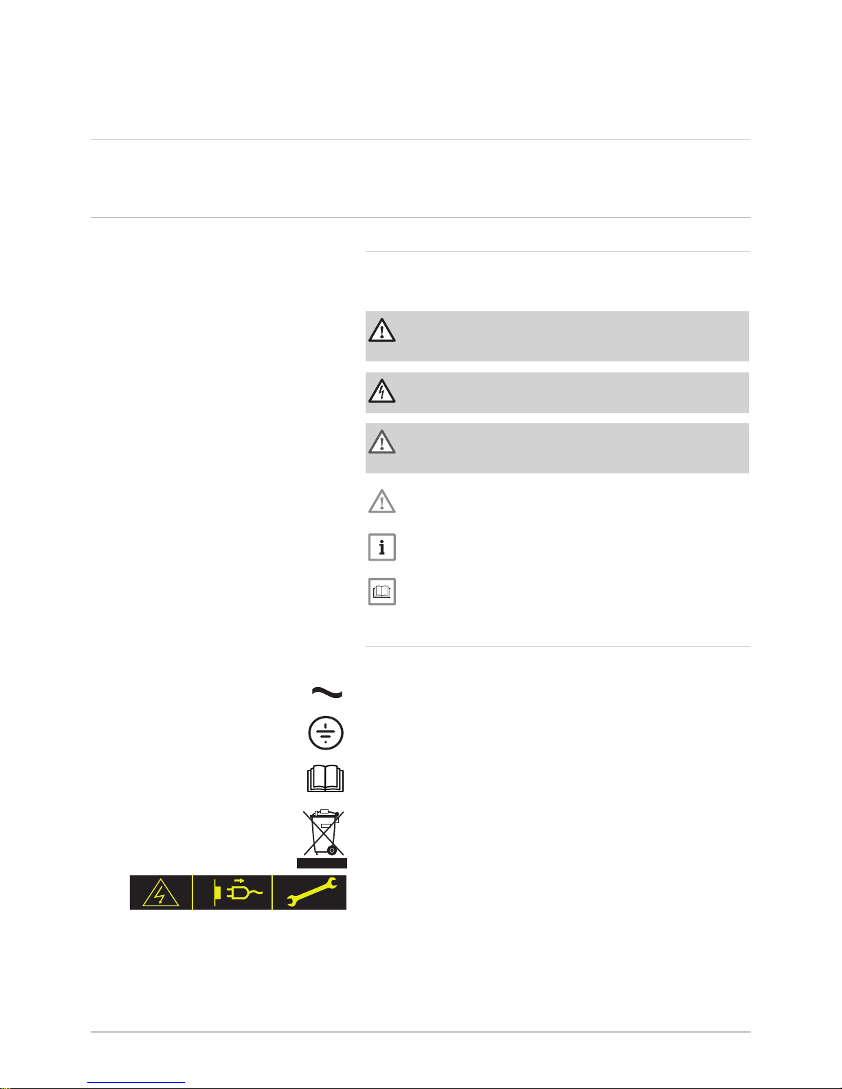
2.2.2 Symbols used on the appliance
1 Alternating current.
2 Protective earthing.
3 Before installing and commissioning the appliance, carefully read
the instruction manuals provided.
4 Dispose of used products through an appropriate recovery and re
cycling structure.
5 Caution: danger of electric shock, live parts. Disconnect the mains
power prior to carrying out any work.
Fig.1 Symbols used on the appliance
1 2
MW-2000068-1
1
2
3
4
5
2 About this manual
7611973 - v04 - 07032016 AWHP-2 MIV-3 11
Page 12

3 Technical specifications
3.1 Heat pump
Maximum operating pressure: 3 bar
Tab.3 Conditions of use
Water (°C) Outside air (°C)
Limit operating temperatures in Heating
mode
+18 / +60 AWHP 4 MR, AWHP 6 MR-2 : -15 / +35
Other models: -20 / +35
Limit operating temperatures in Cooling
mode (MIV-3/EM, MIV-3/ET, MIV-3/H)
+18 / +25 +7 / +40
Limit operating temperatures in Cooling
mode (MIV-3/EMI, MIV-3/ETI, MIV-3/HI)
+7 / +25 +7 / +40
Tab.4 Heating mode: outside air temperature +7°C, water temperature at the outlet +35°C. Performances in accordance with
EN 14511-2.
Measurement type Unit AWHP
4 MR
AWHP 6
MR-2
AWHP 8
MR-2
AWHP 11
MR-2
AWHP 11
TR-2
AWHP 16
MR-2
AWHP 16
TR-2
Heat output kW 3.94 5.73 8.26 11.39 11.39 14.65 14.65
Coefficient of per
formance (COP)
4.53 4.04 4.27 4.65 4.65 4.22 4.22
Absorbed electrical
power
kWe 0.87 1.42 1.93 2.45 2.45 3.47 3.47
Nominal amperage A 4.11 6.57 8.99 11.41 3.8 16.17 5.39
Nominal water flow
rate (ΔT = 5K)
m3/hour
0.68 0.99 1.42 1.96 1.96 2.53 2.53
Tab.5 Heating mode: outside air temperature +2 °C, water temperature at the outlet +35°C. Performances in accordance with
EN 14511-2.
Measurement
type
Unit AWHP 4 MRAWHP 6
MR-2
AWHP 8
MR-2
AWHP 11
MR-2
AWHP 11
TR-2
AWHP 16
MR-2
AWHP 16
TR-2
Heat output kW 3.76 3.65 5.30 10.19 10.19 12.90 12.90
Coefficient of
performance
(COP)
3.32 3.22 3.46 3.20 3.20 3.27 3.27
Absorbed elec
trical power
kWe 1.13 1.16 1.53 3.19 3.19 3.94 3.94
Tab.6 Cooling mode: outside air temperature +35°C, water temperature at the outlet +18°C. Performances in accordance with
EN 14511-2.
Measurement
type
Unit AWHP 4 MRAWHP 6
MR-2
AWHP 8
MR-2
AWHP 11
MR-2
AWHP 11
TR-2
AWHP 16
MR-2
AWHP 16
TR-2
Cooling output kW 3.84 4.69 7.90 11.16 11.16 14.46 14.46
Energy efficien
cy ratio
4.83 4.09 3.99 4.75 4.75 3.96 3.96
Absorbed elec
trical power
kWe 0.72 1.15 2.00 2.35 2.35 3.65 3.65
Nominal am
perage
A 3.40 5.43 9.40 11.05 3.68 17.15 5.71
3 Technical specifications
12 AWHP-2 MIV-3 7611973 - v04 - 07032016
Page 13

Tab.7 Common specifications
Measurement
type
Unit AWHP 4 MRAWHP 6
MR-2
AWHP 8
MR-2
AWHP 11
MR-2
AWHP 11
TR-2
AWHP 16
MR-2
AWHP 16
TR-2
Total dynamic
head at nominal
flow rate
kPa 58 49 29 11 11 – –
Nominal air flow
rate
m3/hour
2100 2100 3300 6000 6000 6000 6000
Power voltage of
the outdoor unit
V 230 230 230 230 400 230 400
Start-up amper
age
A 5 5 5 5 3 6 3
Maximal amper
age
A 13 13 19 29.5 13 29.5 13
Acoustic power Inside
(1)
dB(A) 52.9 52.9 53.3 53.3 53.3 53.3 53.3
Acoustic power Outside
(1)
dB(A) 62.4 64.8 65.2 68.8 68.8 68.5 68.5
Acoustic pres
sure
(2)
dB(A) 41.7 41.7 43.2 43.4 43.4 47.4 47.4
Standby output W 16.4 15 18 21.1 21.1 21.1 21.1
Refrigerant fluid
R410A
kg 2.1 2.1 3.2 4.6 4.6 4.6 4.6
Refrigerant fluid
R410A
equiv. kg
CO
2
4384 4384 6680 9603 9603 9603 9603
Refrigeration
connection (Liq
uid/Gas)
inch 1/4 - 1/2 1/4 - 1/2 3/8 – 5/8 3/8 – 5/8 3/8 – 5/8 3/8 – 5/8 3/8 – 5/8
Max. pre-loaded
length
m 10 10 10 10 10 10 10
Weight (empty) Outdoor unit
kg 42 42 75 118 118 130 130
Weight (empty) Indoor module
kg 52 52 52 55 55 55 55
(1) Noise radiated by the envelope - Test run in accordance with the NF EN 12102 standard, temperature conditions: air 7°C, water 55°C
(2) at 5 m from the appliance, free field
3.1.1 Other technical parameters
Tab.8 Technical parameters for heat pump space heaters (parameters declared for medium-temperature application)
AWHP-2 MIV-3 AWHP 4 MR AWHP 6 MR-2 AWHP 8 MR-2
Air-to-water heat pump Yes Yes Yes
Water-to-water heat pump No No No
Brine-to-water heat pump No No No
Low-temperature heat pump No No No
Equipped with a supplementary heater Yes Yes Yes
Heat pump combination heater No No No
Rated heat output under average conditions
(1)
Prated
kW 2 4 6
Rated heat output under colder conditions
Prated
kW 2 4 6
Rated heat output under warmer conditions
Prated
kW 3 5 6
3 Technical specifications
7611973 - v04 - 07032016 AWHP-2 MIV-3 13
Page 14

AWHP-2 MIV-3 AWHP 4 MR AWHP 6 MR-2 AWHP 8 MR-2
Declared capacity for heating for part load at in
door temperature 20 °C and outdoor temperature
T
j
T
j
= -7 °C
Pdh
kW 2.4 3.5 5.6
T
j
= +2 °C
Pdh
kW 3.4 4.5 6.1
T
j
= +7 °C
Pdh
kW 4.0 4.8 6.4
T
j
= +12 °C
Pdh
kW 4.2 5.2 6.7
T
j
= bivalent temperature
Pdh
kW 2.0 3.6 5.6
Bivalent temperature
T
biv
°C -10 -10 -10
Degradation coefficient
(2)
Cdh
— 1.0 1.0 1.0
Seasonal space heating energy efficiency under
average conditions
ƞ
s
% 131 137 136
Seasonal space heating energy efficiency under
colder conditions
ƞ
s
% 109 116 119
Seasonal space heating energy efficiency under
warmer conditions
ƞ
s
% 167 172 169
Declared coefficient of performance or primary
energy ratio for part load at indoor temperature
20 °C and outdoor temperature
T
j
T
j
= -7 °C
COPd
- 1.80 1.89 1.95
T
j
= +2 °C
COPd
- 3.47 3.53 3.49
T
j
= +7 °C
COPd
- 4.70 4.74 4.57
T
j
= +12 °C
COPd
- 7.03 7.08 6.33
T
j
= bivalent temperature
COPd
- 1.45 1.52 1.63
Heating water operating limit temperature
WTOL
°C 60 60 60
Electrical power consumption
Off mode
P
OFF
kW 0.009 0.009 0.009
Thermostat-off mode
P
TO
kW 0.049 0.049 0.049
Stand-by
P
SB
kW 0.013 0.013 0.013
Crankcase heater mode
P
CK
kW 0.055 0.055 0.055
Supplementary heater
Rated heat output
(1)
Psup
kW 0.0 0.0 0.0
Type of energy input Electricity Electricity Electricity
Other characteristics
Capacity control Variable Variable Variable
Sound power level, indoors - outdoors
L
WA
dB (A) 53 - 64 53 - 65 53 - 65
Annual energy consumption under average
conditions
Q
HE
kWh
GJ
1228 2124 3316
Annual energy consumption under colder con
ditions
Q
HE
kWh
GJ
1965 3721 4621
Annual energy consumption under warmer
conditions
Q
HE
kWh
GJ
970 1492 1904
(1) The rated heat output
Prated
is equal to the design load for heating
Pdesignh
, and the rated heat output of a supplementary heater
Psup
is equal to the supplementary capacity for heating
sup(Tj).
(2) If
Cdh
is not determined by measurement, the default degradation coefficient is
Cdh
= 0.9.
3 Technical specifications
14 AWHP-2 MIV-3 7611973 - v04 - 07032016
Page 15

Tab.9 Technical parameters for heat pump space heaters (parameters declared for medium-temperature application)
AWHP-2 MIV-3 AWHP 11 MR-2
AWHP 11 TR-2
AWHP 16 MR-2
AWHP 16 TR-2
Air-to-water heat pump Yes Yes
Water-to-water heat pump No No
Brine-to-water heat pump No No
Low-temperature heat pump No No
Equipped with a supplementary heater Yes Yes
Heat pump combination heater No No
Rated heat output under average conditions
(1)
Prated
kW 6 8
Rated heat output under colder conditions
Prated
kW 4 7
Rated heat output under warmer conditions
Prated
kW 8 13
Declared capacity for heating for part load at indoor tem
perature 20 °C and outdoor temperature
T
j
T
j
= -7 °C
Pdh
kW 6.8 9.0
T
j
= +2 °C
Pdh
kW 8.2 11.9
T
j
= +7 °C
Pdh
kW 9.0 12.9
T
j
= +12 °C
Pdh
kW 10.1 15.4
T
j
= bivalent temperature
Pdh
kW 6.2 8.3
Bivalent temperature
T
biv
°C -10 -10
Degradation coefficient
(2)
Cdh
— 1.0 1.0
Seasonal space heating energy efficiency under average
conditions
ƞ
s
% 132 130
Seasonal space heating energy efficiency under colder
conditions
ƞ
s
% 113 113
Seasonal space heating energy efficiency under warmer
conditions
ƞ
s
% 167 161
Declared coefficient of performance or primary energy ra
tio for part load at indoor temperature 20 °C and outdoor
temperature
T
j
T
j
= -7 °C
COPd
- 1.82 1.88
T
j
= +2 °C
COPd
- 3.43 3.33
T
j
= +7 °C
COPd
- 4.54 4.34
T
j
= +12 °C
COPd
- 6.24 5.82
T
j
= bivalent temperature
COPd
- 1.45 1.54
Heating water operating limit temperature
WTOL
°C 60 60
Electrical power consumption
Off mode
P
OFF
kW 0.009 0.009
Thermostat-off mode
P
TO
kW 0.049 0.049
Stand-by
P
SB
kW 0.013 0.013
Crankcase heater mode
P
CK
kW 0.055 0.055
Supplementary heater
Rated heat output
(1)
Psup
kW 0.0 0.0
Type of energy input Electricity Electricity
Other characteristics
Capacity control Variable Variable
3 Technical specifications
7611973 - v04 - 07032016 AWHP-2 MIV-3 15
Page 16

AWHP-2 MIV-3 AWHP 11 MR-2
AWHP 11 TR-2
AWHP 16 MR-2
AWHP 16 TR-2
Sound power level, indoors - outdoors
L
WA
dB (A) 53 - 69 53 - 69
Annual energy consumption under average conditions
Q
HE
kWh
GJ
3783 5184
Annual energy consumption under colder conditions
Q
HE
kWh
GJ
3804 5684
Annual energy consumption under warmer conditions
Q
HE
kWh
GJ
2580 4120
(1) The rated heat output
Prated
is equal to the design load for heating
Pdesignh
, and the rated heat output of a supplementary heater
Psup
is equal to the supplementary capacity for heating
sup(Tj).
(2) If
Cdh
is not determined by measurement, the default degradation coefficient is
Cdh
= 0.9.
3.2
Sensor characteristics
Tab.10 Outside temperature sensor
Temperature in °C -20 -16 -12 -8 -4 0 4 8 12 16 20 24
Resistance in Ω 2392 2088 1811 1562 1342 1149 984 842 720 616 528 454
Tab.11 Domestic hot water sensor, flow sensor
Temperature in °C 0 10 20 25 30 40 50 60 70 80 90
Resistance in Ω 32014 19691 12474 10000 8080 5372 3661 2535 1794 1290 941
3 Technical specifications
16 AWHP-2 MIV-3 7611973 - v04 - 07032016
Page 17

4 Description of the product
4.1 General description
The ALEZIO EVOLUTION heat pump comprises:
An outdoor unit for energy production in heating mode only when it is
combined with an uninsulated indoor module.
A reversible outdoor unit for energy production in heating or cooling
mode when it is combined with an insulated indoor module.
An indoor module with a control panel to handle the heat exchange be
tween the R410A fluid and the hydraulic circuit.
Both units are connected by means of refrigeration and electrical connec
tions.
The system offers the following advantages:
The heating circuit is housed in the insulated volume within the home.
Thanks to the DC inverter system, the heat pump modulates its output
to adapt to the needs of the home.
The control panel uses the outside sensor to adjust the temperature of
the heating circuit according to the outside temperature.
4.2
Operating principle
4.2.1 Circulation pump
Note
The benchmark for the most efficient circulators is EEI ≤ 0.20.
4.2.2 Hybrid operating mode
Note
The hybrid operating mode is only available for appliances with
hydraulic back-up.
The appliance offers a choice between several hybrid operating modes.
The modes available offer either optimised energy consumption according
to energy cost, or optimised energy consumption according to primary en
ergy consumption. Both hybrid operating modes are available via the pa
rameter .
In optimised primary energy consumption mode, the control system
chooses the generator that consumes the least primary energy.
In optimised energy cost mode, the control system chooses the cheap
est generator according to the coefficient of performance of the heat
pump and according to energy cost.
4 Description of the product
7611973 - v04 - 07032016 AWHP-2 MIV-3 17
Page 18

4.3 Control panel description
4.3.1 Description of the keys
Fig.2 Control panel
MW-M002226-1
1
7
6 5 4
2 3
9
8
1 Display
2 On/Off switch
3 Pressure gauge
4 Confirm key or
5 Domestic hot water temperature key or
6 Heating temperature key or
7 [Escape] key
8 Back-up forcing key
9 Menu key
4.3.2 Description of the display
The display shows the operating status of the heat pump, the heating flow
temperature and any error codes.
1 Menus:
: Information menu display
: User menu
: Installer settings
2 Operating modes:
: Domestic hot water mode
: Cooling mode (only for the reversible versions)
: Shut-down/Frost Protection mode
: Heating mode
: Compressor on
: Back-up on, stage 1-2
3 Forced back-up:
+ : Heating
+ : Domestic hot water
+ + : Heating + domestic hot water
Other Information:
: Fault active
: Adjusting the set point temperatures
: A manual venting cycle is running / Permanent display of
the information menu / The screed drying function is active.
Fig.3 Display
MW-M002227-1
1
3
2
4 Description of the product
18 AWHP-2 MIV-3 7611973 - v04 - 07032016
Page 19

5 Operation
5.1 Use of the control panel
1. Use the key to select the various menus. Press the key the num
ber of times necessary to access the desired menu:
1 X Information menu
2 X User menu
3 X Installer Menu
2. Confirm by pressing the key.
3. Exit the menu by pressing the key.
5.2
Starting the heat pump
1. Start the heat pump to produce heating, domestic hot water or cool
ing (cooling mode: only for the reversible versions).
Caution
Only qualified professionals may carry out initial commissioning or
a start-up when the heat pump has completely stopped.
2. To restart a heat pump in shut-down/frost protection mode, change
the operating mode.
For more information, see
Changing the operating mode, page 22
5.3 Switching off the central heating
It is possible to shut down the central heating and select an operating
mode suited to the situation and the desired comfort level:
In summer, for the sake of comfort, it is possible to operate cooling
(only for the reversible versions).
In the event of a prolonged absence (weekend, holiday), it is possible to
switch to shut-down/frost protection mode.
It is possible to produce domestic hot water all year round.
Caution
It is recommended that the heat pump never be completely shut
down. Frost protection is no longer automatically guaranteed if the
mains supply is switched off.
For more information, see
User settings, page 22
5.4
Frost Protection
When the outside temperature drops too low, the appliance's protection
system starts up. Frost protection is handled by the back-up. The back-up
is tripped automatically to handle frost protection under the following con
ditions:
Fig.4 Shut-down/Frost Protection mode
MW-M002239-1
5 Operation
7611973 - v04 - 07032016 AWHP-2 MIV-3 19
Page 20

Tab.12 Frost protection conditions
Frost protection Conditions
Heating circuit Outside temperature: < 3°C
Heating flow temperature: < 6°C
Protection of the domestic hot wa
ter tank
Outside temperature: < 3°C
Domestic hot water temperature: < 4°C
5 Operation
20 AWHP-2 MIV-3 7611973 - v04 - 07032016
Page 21

6 Settings
6.1 List of parameters
6.1.1 Choosing the hybrid operating mode
Parameter Description Adjustment range Increment Factory set
ting
(1)
Hybrid operating mode 0 to 2
0 = Deactivated
1 = Optimisation of primary energy consump
tion
2 = Optimisation according to energy cost
1 0
(1) Only available if = 0
Note
It is imperative that you input the energy cost parameters ,
and to use the hybrid operating mode optimised according
to energy cost
6.1.2 Energy cost parameters
Caution
The currency for parameters , and must be the
same. Example: in euro per kWh and in euro per litre.
Note
The parameters , and are available only if = 2.
Tab.13 Energy cost parameter
Parameter Description Adjustment
range
Increment Factory setting
(1)
Tariff per kWh of electricity
For a standard electricity tariff, input the parame
ter .
0.01 to 2.00 0.01 0.13
Tariff per kWh of electricity (off-peak hours)
For a Peak Hours / Off-peak Hours electricity tar
iff, input the parameters for the Peak Hours
tariff and for the Off-peak Hours tariff.
0.01 to 2.00 0.01 0.09
Fossil energy tariff for the hydraulic back-up
Gas boiler: Tariff per m3 of gas. Example: €/m
3
Oil boiler: Tariff per litre of oil. Example: €/litre
0.01 to 2.50 0.01 0.9
(1) Only available if = 0
6 Settings
7611973 - v04 - 07032016 AWHP-2 MIV-3 21
Page 22

6.2 User settings
Note
If no keys are pressed, the settings menus are exited automatical
ly after 10 seconds without saving the parameters.
6.2.1 Changing the operating mode
1. Press the key twice to modify the operating mode.
2. When the symbol flashes on the display, press the key.
3. Press the and keys to modify the operating mode.
Operating mode Value Screen display
Heating and domestic hot water 1 +
Heating 2
Domestic hot water 3
Cooling and domestic hot water 4 + +
Cooling 5 +
Shut-down/Frost Protection mode 6
Swimming pool 7
Swimming pool and domestic hot water 8 +
4. Press the key to confirm and exit the menu.
Fig.5 Enter the user menu
MW-M002249-1
2x
Fig.6 Confirming access to the user menu
M002250-B
Fig.7 Modifying the value
M002251-B
6 Settings
22 AWHP-2 MIV-3 7611973 - v04 - 07032016
Page 23

6.2.2 Forcing the back-up
Note
It is impossible to force the back-up when the shut-down/frost pro
tection mode is selected.
It is possible to force use of the back-up to complement the heat pump. To
force use of the back-up, perform the following operations:
1. Press the and keys simultaneously.
2. Hold the key down and press the key successively to choose
the forcing desired.
Display Back-up
+ Forcing the back-up for heating
+ Forcing the back-up for domes
tic hot water
+ + Forcing the back-up for heating
and domestic hot water
The symbol disappears from
the display.
Back-up forcing deactivated
6.2.3
Modifying the room temperature set point
1. Press the key.
2. Use the or keys to modify the value.
Tab.14 Room temperature set point parameter
Temperature Adjustment
range
Increment Factory setting
Room temper
ature set point
from 15 to 30 °C1 °C 20°C
3. Press the key to confirm and exit the menu.
Note
When a room thermostat is connected, set it to a value 2 K higher
than the room temperature set point .
Fig.8 Accessing the forcing function
M002261-C
Fig.9 Forcing selection
M002264-D
Fig.10 Press the key
M002240-B
Fig.11 Modifying the value
M002241-B
6 Settings
7611973 - v04 - 07032016 AWHP-2 MIV-3 23
Page 24

6.2.4 Configuring the hybrid operating mode
1. Press the key three times.
2. The symbol flashes. Press the key.
3. Use the and keys to switch from one parameter to another.
4. Use the and keys to modify the parameter value.
5. Press the key to confirm the setting.
Note
To modify another parameter, repeat the procedure from step 3.
6. Press the key to exit the menu.
For more information, see
Choosing the hybrid operating mode, page 21
6.2.5 Modifying the domestic hot water temperature
1. Press the key.
2. Use the or keys to modify the value.
Tab.15 Domestic hot water temperature parameter
Temperature Adjustment
range
Increment Factory set
ting
Domestic hot wa
ter set point tem
perature
from 40 to
65°C
1 °C 50 °C
3. Press the key to confirm and exit the menu.
Fig.12 Go into the menu
M002253-B
3x
Fig.13 Navigating in the menu
MW-M003105-1
Fig.14 Press the key.
M002243-B
Fig.15 Modifying the value
M002244-B
6 Settings
24 AWHP-2 MIV-3 7611973 - v04 - 07032016
Page 25

6.3 Reading out measured values
6.3.1 Displaying the measured values
1.
Go to the information menu by pressing the key.
2. The symbol flashes. Confirm by pressing the key.
The wording flashes for 5 seconds.
Note
If no keys are pressed for 10 seconds, the screen goes back to
the main display. To stay in the Information menu, press the
key. The wording continues to be displayed and stops
flashing.
3. Scroll through the information using the and keys.
4. Exit the menu by pressing the key.
Information menu
Parameter Description Unit
In heating mode: Heating flow set point temperature
In domestic hot water mode: DHW set point temperature
In cooling mode: Cooling set point temperature
In swimming pool mode: Swimming pool set point temperature
°C
Measured flow temperature °C
Measured domestic hot water temperature °C
Measured outside temperature °C
Water flow rate litres/minute
Fig.16 Information menu
MW-M002246-1
Fig.17 Confirming
M002247-C
Fig.18 Wording
MW-M002278-1
Fig.19 Navigating in the menu
MW-M002248-1
6 Settings
7611973 - v04 - 07032016 AWHP-2 MIV-3 25
Page 26

Parameter Description Unit
Software version
6.3.2 Energy consumption display
Note
The energy consumption is displayed after the information menu
.
Tab.16 Parameters for estimated electrical energy consumption
Parameter Description Unit
Estimated electrical energy consumption in heating mode
(1)
kWh
Estimated electrical energy consumption in domestic hot water mode kWh
Estimated electrical energy consumption in cooling mode
(2)
.
kWh
(1) Display available if the estimated electrical energy consumption function is activated
(2) Cooling mode must be enabled.
Tab.17 Examples of energy consumption displays
Display example Description
Fig.20 Unit 1 kWh
MW-C004232-1
The displayed value is 123 kWh. The unit is 1 kWh.
Fig.21 Unit 10 kWh
C004233-B
The displayed value is 1230 kWh. The unit is 10 kWh. The first digit
indicates the scale x 10. Only the first 3 digits are displayed.
Fig.22 Unit 100 kWh
MW-C004234-1
The displayed value is 12300 kWh. The unit is 100 kWh. The first dig
it indicates the scale x 100. Only the first 3 digits are displayed.
6 Settings
26 AWHP-2 MIV-3 7611973 - v04 - 07032016
Page 27

Display example Description
Fig.23 Unit 1000 kWh
MW-C004235-1
The displayed value is 123000 kWh. The unit is 1000 kWh. The first
digit indicates the scale x 1000. Only the first 3 digits are displayed.
6 Settings
7611973 - v04 - 07032016 AWHP-2 MIV-3 27
Page 28

7 Maintenance
7.1 General instructions
Maintenance operations are important for the following reasons:
To guarantee optimum performance.
To extend the life of the equipment.
To provide an installation which offers the customer optimum comfort
over time.
Caution
An annual service of the heat pump is mandatory.
7.2
Maintenance instructions
1. Check the hydraulic pressure in the installation.
Note
If the water pressure is lower than 1 bar, more water should be
added. If necessary, top up the water level in the heating system
(recommended hydraulic pressure between 1.5 and 2.0 bar, or be
tween 0.15 and 0.2 MPa)..
2. Carry out a visual check for any water leaks.
3. Open and close the radiator valves several times a year.
This helps to prevent the valves from seizing up.
4. Clean the outside of the heat pump using a damp cloth and a mild
detergent.
Caution
Only qualified professionals are permitted to clean the inside of
the heat pump.
7.3
Topping up the installation with water
If necessary, top up the water level in the heating system (recommended
hydraulic pressure between 1.5 and 2 bar, or between 0.15 and 0.2 MPa).
1. Open the valves on all radiators connected to the heating system.
2. Set the room thermostat to as low a temperature as possible.
3. Put the heat pump in shut-down/frost protection mode.
4. Open the fill valve.
5. Close the fill valve when the pressure gauge shows a pressure of
1.5 bar (0.15 MPa).
6. Put the heat pump in heating mode.
7. When the pump has stopped, vent again and top up the water pres
sure.
Note
Filling and venting the installation twice a year should be sufficient
to obtain an adequate hydraulic pressure. If it is often necessary
to top up the installation with water, contact your installer.
7.4
Venting the heating system
It is essential that you vent any air in the domestic hot water tank, the
pipes and the taps to prevent the annoying noises likely to be produced
during heating or when drawing off water.
7.4.1 Manual venting
1. Open the valves on all radiators connected to the heating system.
2. Put the heat pump in shut-down/frost protection mode.
Fig.24 Beware of water leaks
AD-0001507-A
7 Maintenance
28 AWHP-2 MIV-3 7611973 - v04 - 07032016
Page 29

3. Vent the underfloor heating circuits and the radiators. First vent the
lower floors A and then the upper floors B.
Note
The heating pump stops 5 minutes after selection of the shutdown/frost protection mode. If the outside temperature is lower
than 3°C, the heating pump continues to run.
7.4.2
Automatic venting
If the parameter is set to 0, the heat pump runs an automatic vent
ing cycle when it is switched on.
If the parameter is set to 1, a domestic hot water tank is connected.
Automatic venting starts up only if the measured domestic hot water
temperature is lower than 25°C.
Automatic venting takes approximately one minute. It is possible to man
ually extend automatic venting to more than one minute.
1. When powering up, the word flashes. Press the key.
An automatic venting cycle begins. The word stops flashing.
2. Press the key to stop the venting cycle.
Caution
After venting, check whether the pressure in the installation is still
sufficient. Add more water to the installation if necessary.
Fig.25 Venting the floors
MW-M001495-1
AA
BB
7 Maintenance
7611973 - v04 - 07032016 AWHP-2 MIV-3 29
Page 30

8 Troubleshooting
8.1 Error codes
In the event of problems, the control panel displays the symbol and an
error code.
Caution
Make a note of the code displayed.
The error code is important for the correct and rapid diagnosis of
the type of malfunction and for any technical assistance from your
installer.
To go back to the main display, press the key.
The symbol continues to be displayed as long as the error is present.
Navigation is possible in all menus.
Error code Description Probable causes Checking / solution
Configuration error The control system mode is not
compatible with the configuration
of the installer parameters.
Contact the installer.
Flow sensor error.
The heat pump stops
and no control system
modes are available.
Bad connection
Sensor failure
Contact the installer.
Outside temperature
sensor error.
The control system
switches to downgraded
mode with a default out
side temperature of
-20°C.
Bad connection
Sensor failure
Contact the installer.
Domestic hot water sen
sor error.
Production of domestic
hot water is off
Bad connection
Sensor failure
Contact the installer.
Flow rate error The water pressure is too low
Heating water flow rate too low
Close the isolation valves and check
the water pressure with the pressure
gauge.
Too much air Completely vent the indoor module
and the installation for optimum run
ning.
Error on the outdoor unit.
The heat pump stops
and manual back-up
forcing is possible in
heating and domestic hot
water mode.
The outdoor unit stayed on, whilst
the indoor module was off.
Switch off the indoor and outdoor
modules for 3 minutes and then
switch them back on again simul
taneously.
Contact the installer.
Heat pump short-cycle The heat pump set point offset for
domestic hot water production has
not been configured.
Set the parameter .
For AWHP 4 MR and AWHP 6
MR-2, set 5°C.
For AWHP 8 MR-2, set 8°C.
For AWHP 11 MR-2 : set 10°C.
For AWHP 11 TR-2: set 10°C.
For AWHP 16 MR-2 : set to 13°C.
For AWHP 16 TR-2: set 13°C.
8 Troubleshooting
30 AWHP-2 MIV-3 7611973 - v04 - 07032016
Page 31

8.2 Troubleshooting
Problems Probable causes Corrections
The radiators are cold. The heating set point tem
perature is too low.
Increase the value of parameter or, if a room thermostat is connec
ted, increase the temperature on it.
The heating mode is deac
tivated.
Activate the heating mode.
The radiator valves are
closed.
Open the valves on all radiators connected to the heating system.
The heat pump is not op
erating.
Check that the heat pump is switched on.
Check the fuses and switches on the electrical installation.
The water pressure is too
low (< 1 bar).
Top up the installation with water.
There is no domestic
hot water.
The domestic hot water
set point temperature is
too low.
Increase the value of parameter .
The domestic hot water
mode is deactivated.
Activate the domestic hot water mode.
The energy-saving shower
head is restricting the wa
ter flow.
Clean the shower head; replace it if necessary.
The heat pump is not op
erating.
Check that the heat pump is switched on.
Check the fuses and switches on the electrical installation.
The water pressure is too
low (< 1 bar).
Top up the installation with water.
Significant variations in
domestic hot water
temperature
Insufficient water supply Check the water pressure in the installation.
Open the valve.
The heat pump does
not work.
The heating set point tem
perature is too low.
Increase the value of parameter or, if a room thermostat is connec
ted, increase the temperature on it.
The heat pump is not op
erating.
Check that the heat pump is switched on.
Check the fuses and switches on the electrical installation.
The water pressure is too
low (< 1 bar).
Top up the system with water.
An error code appears on
the display.
Correct the error if possible.
The water pressure is
too low (< 1 bar).
Not enough water in the
installation.
Top up the system with water.
Water leak. Contact the installer.
Clicking in the central
heating pipes
.
The central heating pipe
clamps are too tight.
Contact the installer.
There is air in the heating
pipes.
It is essential that you vent any air in the domestic hot water tank, the
pipes and the taps to prevent the annoying noises likely to be produced
during heating or when drawing off water.
The water is circulating too
quickly in the central heat
ing system.
Contact the installer.
Significant water leak
underneath or in the
vicinity of the heat
pump.
The pipes on the heat
pump or the central heat
ing are damaged.
Contact the installer.
8 Troubleshooting
7611973 - v04 - 07032016 AWHP-2 MIV-3 31
Page 32

9 Decommissioning procedure
To decommission the heat pump temporarily or permanently:
1. Contact the installer.
9 Decommissioning procedure
32 AWHP-2 MIV-3 7611973 - v04 - 07032016
Page 33

10 Environmental
10.1 Energy savings
Tips on saving energy:
Do not block ventilation outlets.
Do not cover the radiators. Do not hang curtains in front of the radiators.
Install reflective panels behind the radiators to prevent heat losses.
Insulate the pipes in rooms that are not heated (cellars and lofts).
Turn off the radiators in rooms not being used.
Do not run hot (or cold) water pointlessly.
Install a water-saving shower head to save up to 40% energy.
Take showers rather than baths. A bath consumes twice as much water
and energy.
10.2
Room thermostat and settings
Various models of room thermostat are available. The type of thermostat
used and the parameter selected impact total energy consumption.
A modulating regulator, which may be combined with thermostatic
valves, is eco-friendly in terms of energy and offers an excellent level of
comfort. This combination allows you to set the temperature separately
for each room. However, do not install thermostatic radiator valves in the
room in which the room thermostat is located.
Complete opening and closing of the thermostatic radiator valves cau
ses undesirable variations in temperature. Therefore, these must be
opened/closed progressively.
Set the room thermostat to a temperature of approximately 20°C to re
duce heating costs and energy consumption.
Lower the thermostat setting to approximately 16°C at night or when you
are not at home. This reduces heating costs and energy consumption.
Lower the thermostat setting well before airing the rooms.
Set the water temperature to a lower level in summer than in winter (e.g.
60°C and 80°C respectively) when an ON/OFF thermostat
is used.
When clock thermostats and programmable thermostats are to be set,
do not forget to take any holidays and days when no one is at home into
account.
10 Environmental
7611973 - v04 - 07032016 AWHP-2 MIV-3 33
Page 34

11 Disposal/recycling
11.1 Disposal and Recycling
Warning
Removal and disposal of the heat pump must be carried out by a
qualified professional in accordance with prevailing local and na
tional regulations.
Fig.26 Recycling
MW-3000179-03
11 Disposal/recycling
34 AWHP-2 MIV-3 7611973 - v04 - 07032016
Page 35

12 Warranty
12.1 General
We would like to thank you for buying one of our appliances and for your
trust in our product.
In order to ensure continued safe and efficient operation we recommend
that the product is regularly inspected and maintained.
Your installer and our service department can assist with this.
12.2
Terms of warranty
The following provisions do not affect the application, in favour of the buy
er, of the legal provisions with regard to hidden defects that are applicable
in the buyer's country.
This appliance comes with a warranty that covers all manufacturing faults;
the warranty period will commence on the date of purchase stated on the
installer's invoice.
The warranty period is stated in our price list.
As a manufacturer, we can by no means be held liable if the appliance is
used incorrectly, is poorly maintained or not maintained at all, or is not in
stalled correctly (it is your responsibility to ensure that installation is carried
out by a qualified installer).
In particular, we cannot be held liable for material damage, intangible los
ses or physical injury resulting from an installation that does not comply
with:
Legal or regulatory requirements or provisions laid down by the local au
thorities,
National or local regulations and special provisions relating to the instal
lation,
Our manuals and installation instructions, in particular in terms of regular
maintenance of the appliances,
Our warranty is limited to the replacement or repair of the parts found to
be defective by our technical services team, excluding labour, transfer and
transport costs.
Our warranty does not cover replacement or repair costs for parts that may
become defective due to normal wear, incorrect usage, the intervention of
unqualified third parties, inadequate or insufficient supervision or mainte
nance, a mains supply that is not appropriate or the use of unsuitable or
poor quality fuel.
Smaller parts, such as motors, pumps, electrical valves etc., are guaran
teed only if these parts have never been dismantled.
The rights established in European Directive 99/44/EEC, implemented by
legal decree No. 24 of 2 February 2002 and published in Official Journal
No. 57 of 8 March 2002, remain in force.
12 Warranty
7611973 - v04 - 07032016 AWHP-2 MIV-3 35
Page 36

13 Appendix
13.1 Product fiche
Tab.18 Product fiche for heat pump space heaters
AWHP 4 MR AWHP 6
MR-2
AWHP 8
MR-2
Space heating energy efficiency class under average climate
conditions
A++A++A
++
Rated heat output under average climate conditions
(Prated or
Psup)
kW 2 4 6
Seasonal space heating energy efficiency under average cli
mate conditions
% 131 137 136
Annual energy consumption kWh 1228 2124 3316
Sound power level LWA indoors
(1)
dB (A) 53 53 53
Rated heat output, under colder - warmer climate conditions kW 2 - 3 4 - 5 6 - 6
Seasonal space heating energy efficiency, under colder - warm
er climate conditions
% 109 - 167 116 - 172 119 - 169
Annual energy consumption colder - warmer kWh 1965 - 970 3721 - 1492 4621 - 1904
Sound power level LWA outdoors dB (A) 64 65 65
(1) If applicable
Tab.19 Product fiche for heat pump space heaters
AWHP 11 MR-2
AWHP 11 TR-2
AWHP 16 MR-2
AWHP 16 TR-2
Space heating energy efficiency class under average climate conditions
A++A
++
Rated heat output under average climate conditions
(Prated or Psup)
kW 6 8
Seasonal space heating energy efficiency under average climate condi
tions
% 132 130
Annual energy consumption kWh 3783 5184
Sound power level LWA indoors
(1)
dB (A) 53 53
Rated heat output, under colder - warmer climate conditions kW 4 - 8 7 - 13
Seasonal space heating energy efficiency, under colder - warmer climate
conditions
% 113 - 167 113 - 161
Annual energy consumption colder - warmer kWh 3804 - 2580 5684 - 4120
Sound power level LWA outdoors dB (A) 69 69
(1) If applicable.
See
For specific precautions about assembling, installing and main
taining: See Safety Instructions
13.2
Product fiche - Temperature Controls
Tab.20 Product fiche for the temperature controls
Regulator
Class II
Contribution to space heating energy efficiency % 2
13 Appendix
36 AWHP-2 MIV-3 7611973 - v04 - 07032016
Page 37

13.3 Package fiche - Medium-temperature heat pumps
Note
‘Medium-temperature application’ means an application where the
heat pump space heater or heat pump combination heater deliv
ers its declared capacity for heating at an indoor heat exchanger
outlet temperature of 55 °C.
Fig.27 Package fiche for medium-temperature heat pumps indicating the space heating energy efficiency of the package
AD-3000745-01
%
1
‘I’
2
%+
3
%( - ‘I’ ) x ‘II’ = ±
4
%(‘III’ x + ‘IV’ x ) x 0.45 x ( /100) x = +
(1)
A* = 0.95, A = 0.91,
B = 0.86, C = 0.83,
D - G = 0.81
<30%
G F E D C B A A
+
A
++
A
+++
5
%
%+ ‘VI’ =
5
%- ‘V’ =
5
from fi che of solar device
Solar contribution
The energy effi ciency of the package of products provided for in this fi che may not correspond to its actual energy effi ciency once installed
in a building, as this effi ciency is infl uenced by further factors such as heat loss in the distribution system and the dimensioning of the
products in relation to building size and characteristics.
Seasonal space heating energy effi ciency class of package under average climate
Seasonal space heating energy effi ciency of package under average climate
Tank rating
Collector effi ciency (in
%)
Tank volume (in m³) Collector size (in m²)
Seasonal space heating energy effi ciency (in %)
Supplementary boiler
Class I = 1%, Class II = 2%, Class III = 1.5%,
Class IV = 2%, Class V = 3%, Class VI = 4%,
Class VII = 3.5%, Class VIII = 5%
Temperature control
Seasonal space heating energy effi ciency of heat pump
(1) If tank rating is above A, use 0.95
from fi che of boiler
from fi che of temperature control
Colder: Warmer:
Seasonal space heating energy effi ciency under colder and warmer climate conditions
I The value of the seasonal space heating energy efficiency of the
preferential space heater, expressed in %.
II The factor for weighting the heat output of preferential and supple
mentary heaters of a package as set out in the following table.
III The value of the mathematical expression: 294/(11 · Prated),
whereby ‘Prated’ is related to the preferential space heater.
IV The value of the mathematical expression 115/(11 · Prated),
whereby ‘Prated’ is related to the preferential space heater.
13 Appendix
7611973 - v04 - 07032016 AWHP-2 MIV-3 37
Page 38

V The value of the difference between the seasonal space heating
energy efficiencies under average and colder climate conditions,
expressed in %.
VI The value of the difference between the seasonal space heating
energy efficiencies under warmer and average climate conditions,
expressed in %.
Tab.21 Weighting of medium temperature heat pumps
Prated / (Prated + Psup)
(1)(2)
II, package without hot water storage tank II, package with hot water storage tank
0 1.00 1.00
0.1 0.70 0.63
0.2 0.45 0.30
0.3 0.25 0.15
0.4 0.15 0.06
0.5 0.05 0.02
0.6 0.02 0
≥ 0.7 0 0
(1) The intermediate values are calculated by linear interpolation between the two adjacent values.
(2) Prated is related to the preferential space heater or combination heater.
Tab.22 Package efficiency
AWHP 4 MR AWHP 6 MR-2 AWHP 8 MR-2
Seasonal space heating energy efficiency % 150 137 136
Temperature control % + 2 + 2 + 2
Seasonal space heating energy efficiency of package % 152 139 138
Tab.23 Package efficiency
AWHP 11 MR-2
AWHP 11 TR-2
AWHP 16 MR-2
AWHP 16 TR-2
Seasonal space heating energy efficiency % 132 130
Temperature control % + 2 + 2
Seasonal space heating energy efficiency of package % 134 132
13 Appendix
38 AWHP-2 MIV-3 7611973 - v04 - 07032016
Page 39

© Copyright
All technical and technological information contained in these technical instructions, as well as any drawings and technical de
scriptions supplied, remain our property and shall not be multiplied without our prior consent in writing. Subject to alterations.
Page 40

DE DIETRICH THERMIQUE
57, rue de la Gare F- 67580 MERTZWILLER - BP 30
MW-8000005-7
DUEDI S.r.l.
DE DIETRICH SERVICE
BDR Thermea (Czech republic) s.r.o
www.duediclima.it
www.dedietrich.cz
Distributore Ufficiale Esclusivo
De Dietrich-Thermique Italia
www.dedietrich-heiztechnik.com
Freecall 0800 / 201608
Jeseniova 2770/56
130 00 Praha 3
+49 (0)25 72 / 9161-0
+49 (0)25 72 / 9161-102
info@remeha.de
Via Passatore, 12 - 12010
San Defendente di Cervasca
CUNEO
+39 0171 857170
+39 0171 687875
info@duediclima.it
+420 271 001 627
dedietrich@bdrthermea.cz
IT
DE DIETRICH THERMIQUE Iberia S.L.U.
www.dedietrich-calefaccion.es
C/Salvador Espriu, 11
08908 L’HOSPITALET de LLOBREGAT
+34 935 475 850
info@dedietrich-calefaccion.es
ES
129164, Россия, г. Москва
Зубарев переулок, д. 15/1
Бизнес-центр «Чайка Плаза»,
офис 309
+7 (495) 221-31-51
CZ
DE DIETRICH THERMIQUE S.A.S
info@dedietrich.ru
7611973 - v04 - 07032016
7611973-001-04
 Loading...