

Page 1
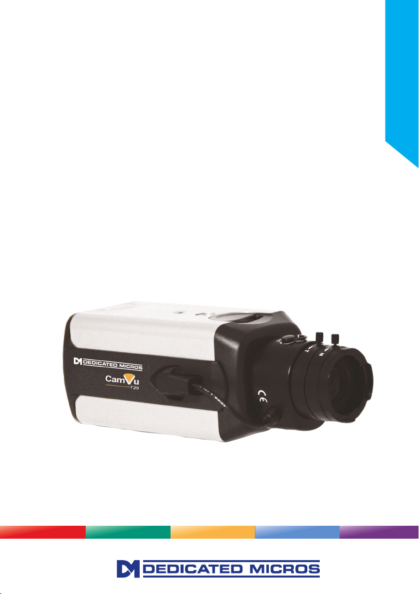
CamVu 720
Installation and
Conguration Manual
DM/CMVU720
DM/CMVU7200/N
Installation Guide
Page 2

Contents
Important Safeguards ....................................................................... 5
Mounting External Domes .............................................................. 14
Conguring the Unit ........................................................................ 19
System ........................................................................................... 22
Display ............................................................................................ 40
Camera ........................................................................................... 45
Dome Settings ................................................................................ 46
ICR Settings ................................................................................... 59
Schedule ........................................................................................ 71
Alarm Settings ...................................................................................... 76
Network Settings ............................................................................ 88
Diagnostics ................................................................................... 102
Unit Operation .............................................................................. 105
Operating the Viewer .................................................................... 106
Appendix A - Unit Specication .................................................... 124
Appendix B - Status Pages .......................................................... 126
Software Version 6.3 (12.0159) OCP1
WebPage Version wp8 1.0 (5984) ns PAL
2
CamVu 720
Page 3

Introduction
1.03
The CamVu720 Series are high denition IP Cameras offering up to 2 megapixel image streams
in a choice of compression formats. With advanced features such as ICR, analytics support and
direct conguration from associated Video Servers, the CamVu720 Series contains a powerful suite
of enterprise-scale capabilities. The CamVu720 Series is also designed for Dedicated Micros next
generation of video surveillance - Closed IPTV.
HIGH DEFINITION STREAMING & RECORDING
The CamVu720 provides high denition image streams up to 2 megapixel, with a congurable resolution
of up to 1280x720 (16:9) and 1600x1200 (4:3). The powerful suite of streaming features ensure exibility
in remote viewing of the camera whilst on-board storage and supported transmission protocols such as
AoE provide a wealth of local and remote recording options..
ANALYTICSCAPABLE
As part of our growing range of AnalyticsCapable products, the CamVu720 Series is able to contain the
latest analytics solutions from Dedicated Micros including Object Left/Removed Detection Tripwire and
Counting Tripwire, all locally hosted on the camera.
NETVU CONNECTED
With NetVu Connected products users can seamlessly integrate Video Servers, Cameras & Domes,
Management Systems, mobile viewing devices and video walls together without the costly impact of
signicant integration time. A shared user interface helps minimise operator training whilst powerful
features such as Direct conguration of PTZ Cameras and Domes from connected DVRs helps reduce
installation time providing benets to both end user and installer/integrator.
The incredible exibility of Dedicated Micros NetVu Connected platform enables multi-environment
security installations to be achieved with ease. Integration of Fixed and Mobile DVRs and Video Servers
alongside products such as FireVu (for Video Smoke Detection) enable large scale solutions with several
application requirements to be designed and built with ease.
Installation Guide
MULTIPLE, SIMULTANEOUS VIDEO STREAMS
Dedicated Micros’ unique Visual Signal Processor (ViSP) allows the CamVu720 Series to transmit multiple
simultaneous MPEG-4, H.264 and/ or JPEG images to any number of associated NetVu Connected
devices for image viewing. Each stream can be tailored to suit the viewer’s bandwidth requirements.
CLOSED IPTV
Dedicated Micros’ award winning Closed IPTV solution combines open standard IP protocols with patent
pending innovation to provide simple to install, safe and secure IP video solutions across new or existing
networks.
Automatically allocating IP addresses to IP cameras by physical port, a Closed IPTV system is completely
deterministic, creating rewalls and monitoring point-to-point IP connections so they cannot be hacked
or intercepted. Critical to the security of a Closed IPTV system is the unique implementation of Trusted
Endpoint technology; a secret signature, applied at lock down, enables endpoint devices such as IP
cameras to be secure, immediately triggering a security alert should any interference be detected.
This ground breaking solution provides a very simple and secure answer to IP video, meaning that no
prior knowledge of IP networking is required. Sophisticated and Dependable network security can be
achieved with a single click.
3
Page 4

Features
■ High denition IP Camera - up to 2MP resolution
■ Available in static camera, internal mini-dome or Vandal Resistant Mini-dome options
■ Integrated Camera Recording and full enterprise video server within camera
■ Can form part of a Closed IPTV system
■ Transmission of multiple, simultaneous video streams in MPEG-4, H.264 and JPEG format
enables multiple users to view video streams at the settings they require
■ AnalyticsCapable - enables analytics solutions to be deployed on your CCTV system
■ Works with any DM Video Server that supports IP Streaming & Recording
■ MultiMode Recording - Dynamically-switchable resolution, record-rate & compression
(MPEG-4/H.264/JPEG) settings
■ Web server for remote conguration of camera features
■ Power over Ethernet (PoE) / 12-24Vdc & 24Vac power options
■ Local analogue test monitor output for use when positioning and adjusting the camera’s eld
of view and focus
■ Can be used externally in a compatible housing such as a DM/2010
■ TransCoding - High quality recording and simultaneous video transmission using MPEG4,
JPEG or H.264 for playback
■ Uses the latest Chipwrights ViSP to minimise power consumption and heat build up
Benets
• The camera supports recording to local SD card and network attached storage using ATA
over Ethernet
• The latest technology provides low light performance superb image quality and colour delity
in variable and high contrast lighting conditions.
• Operates seamlessly within a NetVu Connected network.
• Remote conguration removes the need for multiple revisits
• Images recorded locally on the camera in JPEG format can be viewed over low bandwidth
networks using MPEG-4
• BNC Connector allows local lens adjustment and display of the unit’s network settings on a
service monitor
Models
DM/CMVU720 1/4”VGA DVIP Colour 12-24V/PoE CamVu720
DM/CMVU7200/N 1/4”VGA DVIP Colour 12-24V/PoE NTSC CamVu720 NTSC
4
CamVu 720
Page 5
2
2
3
4
1
3
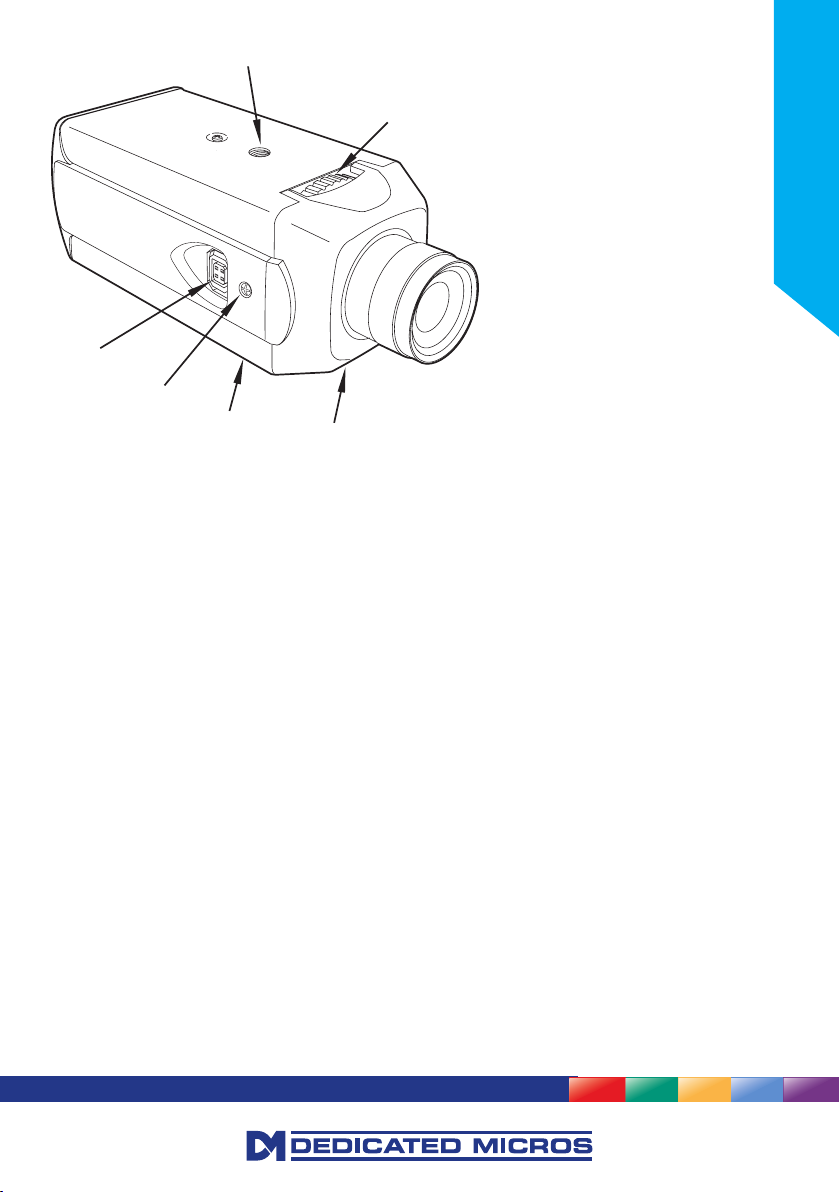
1. Back focus mechanism locking screw (both sides)
2. Back focus adjustment (Top & bottom)
3. Mounting bush (Top & bottom)
4. AI lens connector (DC & video)
Components Supplied
Before installing unit, please verify that all items listed below have been supplied:
1 x CamVu Camera
1 x POE Injector Cable
1 x User Guide
1 x CD containing information for use with the camera
Note: A PSU is not supplied with this camera. A suitable 12Vdc 0.5A PSU is required if powering the
unit from its DC input connector - VS-PSU15W-EXT can be purchased separately from Dedicated
Micros.
If the camera utilises Power Over Ethernet, a separate PSU is not necessary (if power is
available via the Ethernet connection).
Alternatively if powering the unit over PoE using the supplied injector, a 48Vdc PSU that can
supply 15W is required - DM/PSU/48V can be purchased separately from Dedicated Micros.
Installation Guide
5
Page 6

Important Safeguards
Read Instructions
All the safety and operating instructions should be read before the unit is operated and adhered to during
operation. These instructions should be retained with the unit, and all warnings and cautions contained
should be heeded.
Power Sources
This unit should be operated only from the type of power source indicated on the manufacturer’s label.
Power Over Ethernet
This product supports POE and when connected to a suitable switch, will not require an external PSU to
drive the device (Bridge and end-span compatible).
Servicing and Repair
Do not attempt to service this unit yourself as opening or removing covers may expose you to dangerous
voltage or other hazards.
Refer all servicing and repair to qualied service personnel.
Equipment
Use only attachments/accessories specied by the manufacturer.
Ventilation
Ensure unit is properly ventilated to protect from overheating.
Camera Care
In order to avoid damaging your camera, note the following points:
CAUTION
• The camera has threaded mounting points on the top and bottom of the case. Only use a
standard, photographic mounting bolt with a 1/4-20 UNC thread.
• Before tting the lens, make sure that its back will not touch the CMOS sensor or associated
components when screwed fully home.
• Do not touch the image surface of the sensor. If the sensor is accidentally touched, only
clean it using isopropanol.
• Do not expose the camera sensor to very bright light over a long period of time as this
may cause damage to the sensor. The camera and lens set-up must be correct to avoid
possible damage due to long term exposure to bright light. A lens with an automatic iris is
recommended under these conditions.
CE NOTICE (EUROPEAN UNION)
This section contains the regulatory declarations for the EU for the Unit Camera.
This product is marked with the CE symbol and indicates compliance with all applicable Directives. A
“Declaration of Conformity” is held at Dedicated Micros Ltd, 1200 Daresbury Park, Daresbury, Cheshire
WA4 4HS www.dedicatedmicros.com
6
CamVu 720
Page 7

Hereby, Dedicated Micros LTD, declares that this Unit Camera is in compliance with the essential
requirements and other relevant provisions of Directive 95/5/EC.
Marking by the symbol CE indicates compliance of this Dedicated Micros product to the Electromagnetic
Compatibility Directive 89/336/EEC, and the Low Voltage Directive 73/23/EEC of the European Union.
Such marking is indicative that this system meets the following technical standards
• EN 61000-6-3 EMC Standard Residential, Commercial and Light Industry.
• EN 62000-3-3 Limitations of voltage changes, uctuations and icker in public low-voltage
supply systems for equipment with rated current up to 16A.
• EN 61000-3-2 Limits for harmonic current emissions for equipment with rated current up to
16A.
• EN 50130-4 Immunity requirements for components of re, intruder and social alarm
systems.
• EN 60950 Safety of IT and similar equipment.
• EN 55022 Class A. Radiated Emissions Standard, suitable for Commercial or Residential use
Further details about these applicable standards can be obtained from Dedicated Micros Ltd., 1200
Daresbury Park, Daresbury, Cheshire WA4 4HS
1.01002
RF Interference warning
This is a class A product. In a domestic environment this product may cause radio frequency interference
, in which case the user may be required to take adequate measures.
1.01003
Canadian EMC statement
This product is compliant with Class A ICES-003
Note: This Class A product meets the requirements of the Canadian Interference causing equipment
regulations. Cet appareil numerique de la Classe A, respect toutes les exigencies du reglement
sur le materiel brouilleur du Canada.
Installation Guide
4.15
7
Page 8
Installation
1
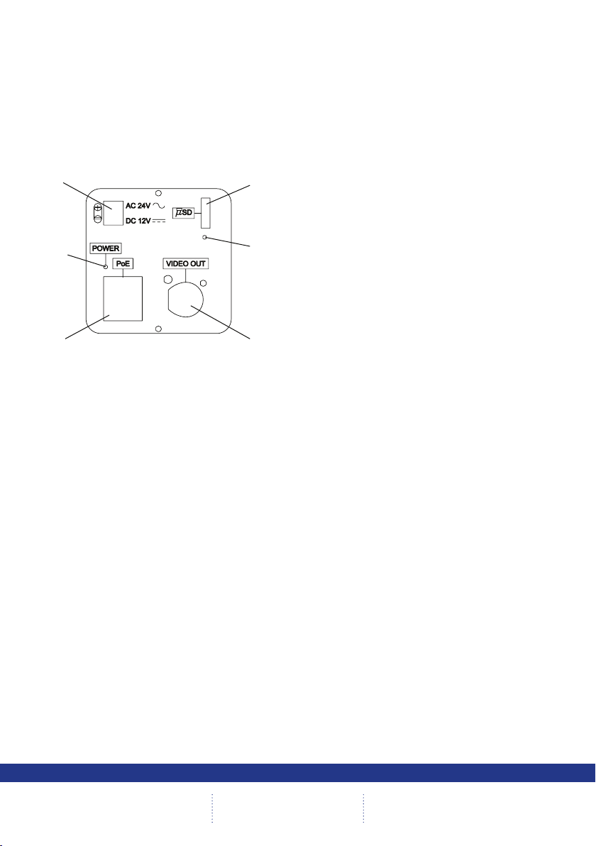
Rear Connections
The CamVu 720 features push t connectors which house connections for 12VDC power. There is also
a PoE capable RJ45 socket for connection to a suitable network point. The BNC video output connection
is used in conjunction with a local monitor to focus the camera during installation and can also be used to
display the camera’s current network settings.
Note: The BNC output only operates for 10 minutes after the camera is powered up.
6
2
3 4
DM/CMVU720
DM/CMVU720/N
1. Low voltage connector (12Vdc/24Vac 50/60Hz)
2. Power indicator LED
3. Power over Ethernet capable RJ45 socket
4. Composite video output BNC
5. MicroSD activity LED
6. MicroSD card slot
5
8
CamVu 720
Page 9

Connections
Power Connections
CamVu720 cameras are available in PoE plus AC/DC low voltage types. The voltage required to operate
the camera is clearly marked on the rear panel of the camera. The power LED on the rear panel indicates
that power is connected.
Power over Ethernet
The camera can be powered from any suitable PoE injector conforming to IEEE 802.3-2008. End span
and bridging injectors supported.
Auto-Switching Low Voltage Power Supply
The camera is tted with an automatic selecting power supply operate between 12 VDC and 24 VAC.
Connections and polarity are indicated beside the connector on the rear panel. The power supply must be
a class 2 isolated type.
Installation Guide
Network Connections
Connection to a 10/100 BaseT network is made via the RJ45 on the rear panel.
Video Connector
Connect a video coaxial cable terminated with a 75Ω BNC connector to the BNC socket marked VIDEO
OUT on the rear of the camera to align the camera.
Note: This video output is only active for 10 minutes after the unit is powered up.
9
Page 10
Lens Connections
C
A
B
Fixed and Manual iris lenses (for indoor use only) require no wiring connections.
Auto Iris Lens
Connect the auto iris lens to the four-pin connector located on the side of the camera. If the lens does
not have a DD plug tted then wire the lens to a suitable plug. Pin connections for the iris drive plug are
shown below.
PIN DIRECT DRIVE AUTO IRIS LENS
1 Control coil positive (+)
2 Control coil negative (-)
3 Drive coil negative (-)
4 Drive coil positive (+)
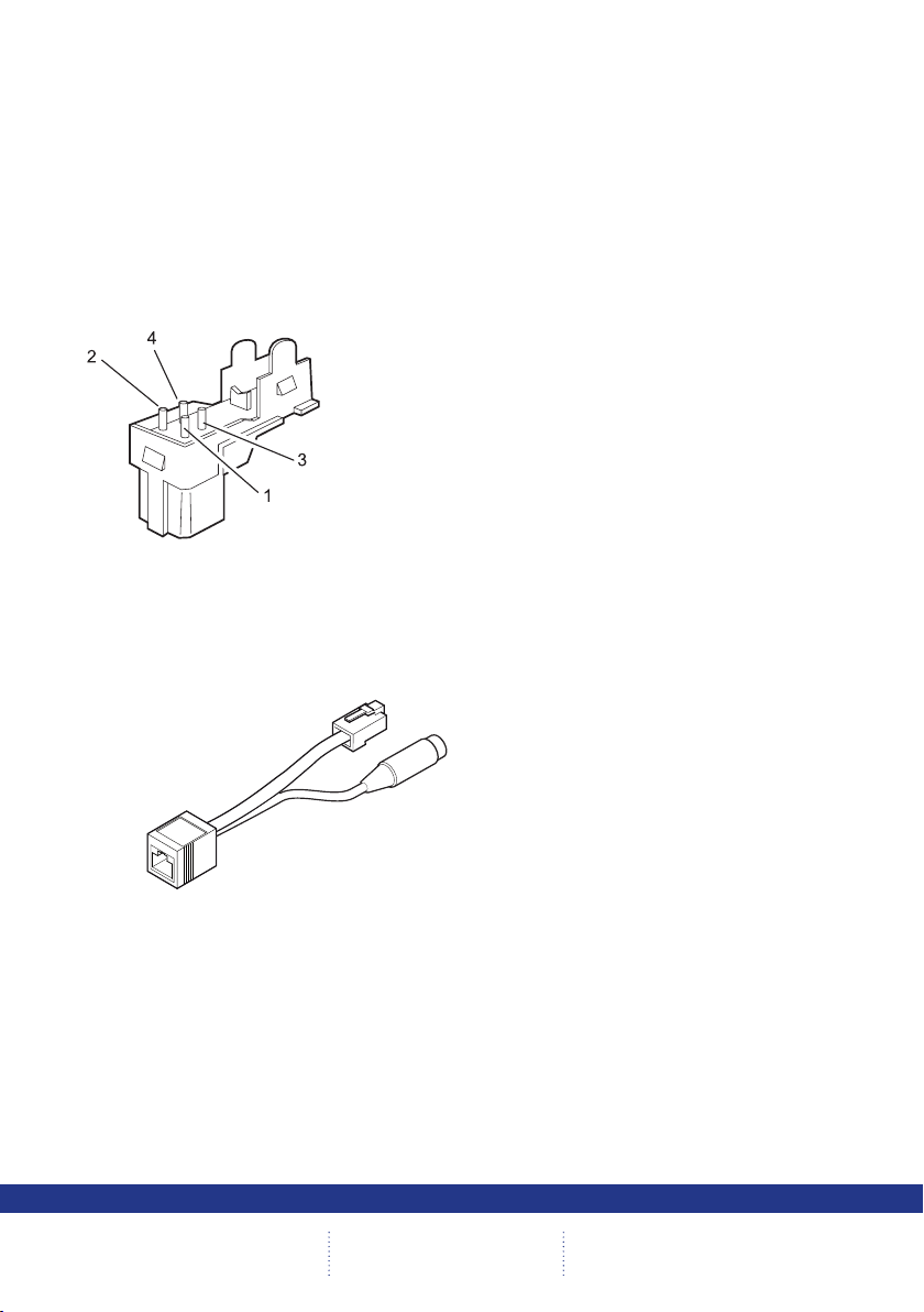
POE Injector Cable
The POE Injector cable is designed to enable the use of POE (Power over Ethernet) before a POE
capable switch has been installed. It is installed alongside a suitable 48Vdc PSU that can supply 15W is
required - DM/PSU/48V can be purchased separately from Dedicated Micros.
A Connection to DVR/NVR/Layer 3 Enhanced CCTV Switch
B Connection to suitable 48Vdc 15W PSU - (DM/PSU/48V)
C Ethernet cable connection to camera.
Important: 48V is supplied to connection C. There is no voltage at Connection A. Do NOT connect
POE Injector Power Supply specication
Adaptor socket - 5.5mm diameter with a 2.1mm central circular pin
+48V goes to the centre pin of the power connector - 0V to the outside barrel
an ethernet cable from connection C to the DVR/Layer 3 Enhanced CCTV Switch as this
could cause irreparable damage.
10
CamVu 720
Page 11

Lenses
Lens Setup Procedures
Back Focus Adjustment
The back focus adjustment is located at the front of the camera and is accessible from either the top or
bottom of the case.
To adjust the back focus:
1. Loosen the two back focus mechanism locking screws (top and bottom of the camera).
2. Turn the back focus ring anti-clockwise (when viewing the front of the camera) until the
CMOS sensor assembly is as far away from the back of the lens as possible.
3. Turn the back focus ring clockwise until focus is achieved.
4. When the back focus adjustment is satisfactory, tighten the locking screws. Do not over-turn
or force the back focus adjustment ring.
Note: Always turn the back focus ring such that during focusing, the CMOS sensor assembly is brought
towards the back of the lens (i.e. clockwise). If the point of best-focus is passed, repeat the back
focus procedure from step 2.
a
b
1
1. Back focus adjustment ring
a. Clockwise
b. Anticlockwise
Installation Guide
11
Page 12
Conguring the Unit
Using the Unit with Secure Closed IPTV
1) Connect the camera to a Closed IP Network switch using Cat5 network cable. The POE
version of this camera will draw power from with the DM/NSW/CPP model switch, or with
DM/NSW/CP model switch if connected to a POE injector and separate power supply.
2) Ensure that the Closed IP NVR or Console that the switch is connected to is in Conguration
mode to allow new cameras connect.
3) Power up the camera and wait for the on-screen acknowledgement on the monitor attached
to the Closed IP NVR or Console. Alternatively check the Camera Overview web page on the
Closed IP NVR or Console to determine out the camera status.
4) Once the camera has been detected and added, remember to secure the switch by moving
out of Conguration mode, failure to do this will leave the Closed IPTV system unsecured.
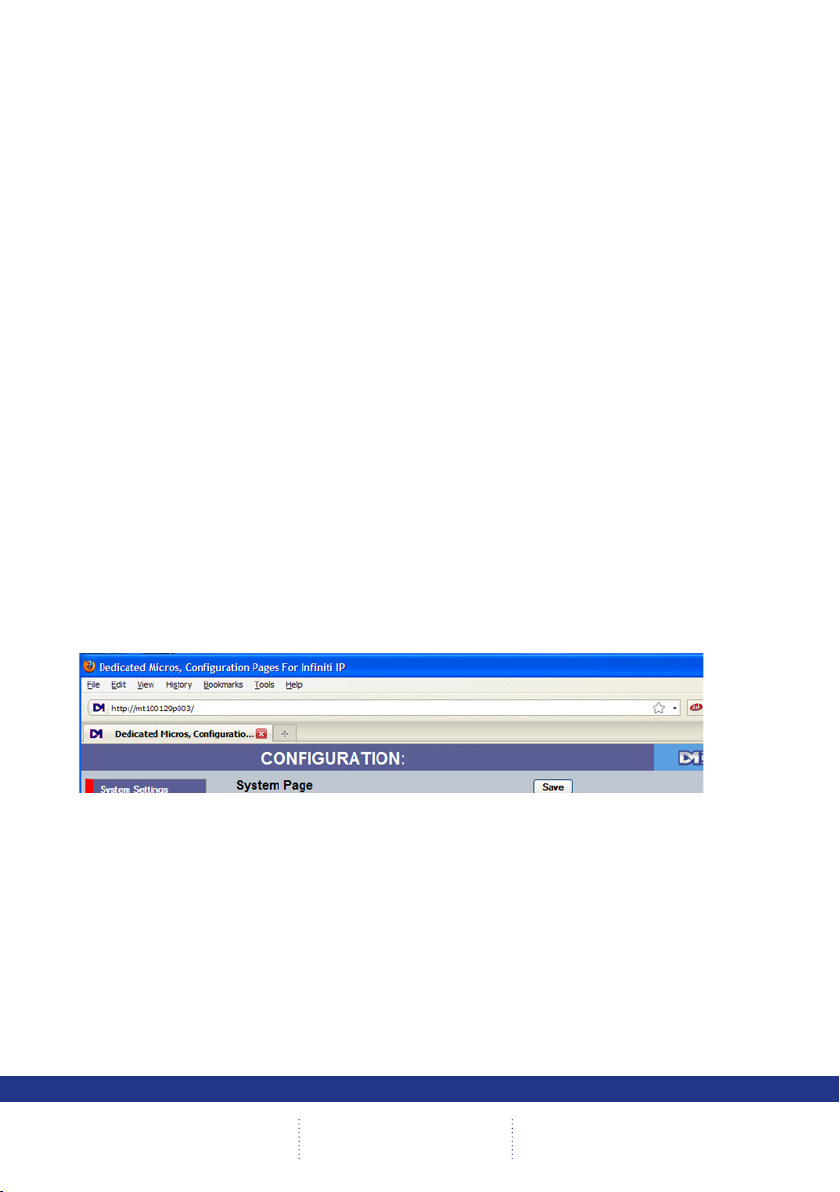
Locating the Unit IP address
The unit is congured using on-board webpages. This can be done remotely once the unit has been
installed in its chosen location, using the web browser on a PC in the same subnet as the unit.
The unit conguration pages can be accessed using the unit IP address or DNS name. The unit has
DHCP factory enabled. When the unit is connected to a DHCP network for the rst time, an IP address is
automatically assigned by the network switch or router it is connected to. Most routers will have the facility
to enable DHCP and DNS, if it is not available, contact your network administrator.
The default DNS address for each unit is factory set as the serial number. This address can be found on
the serial label on the unit or via the packaging the unit came in.
If DHCP and DNS are not available, the IP address can be found by connecting an analogue monitor to
the BNC connection of the camera. The unit IP address is displayed on the analogue video output for 10
minutes from powering the unit on.
The DNS or IP address can be typed directly into the address bar of a web browser.
12
Note: The unit’s DNS address can be changed subsequently to something more memorable or
meaningful than its serial number by editing the System name option in the System conguration
page.
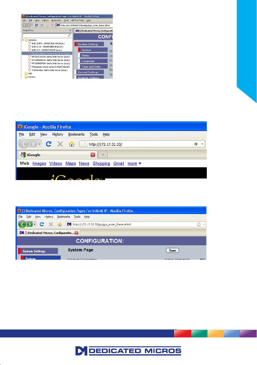
Zero_conf conguration
If a permanent IP address is not assigned to the unit, it will attempt to contact the DHCP server every
time it starts up, and periodically thereafter. The unit support zero-conguration networking (sometimes
known as Bonjour), this enables automatic discovery of computers, devices, and services on IP networks.
Zero-conguration uses industry standard IP protocols to allow devices to automatically discover each
other without the need to enter IP addresses or congure DNS servers. By loading a suitable free add-on
to your web browser such as Bonjour for Windows for Internet Explorer or BonjourFoxy for FireFox zero
conguration devices such as this unit can easily be discovered and accessed.
CamVu 720
Page 13
Accessing the Conguration Pages
The unit is congured using the on-board conguration pages. To access these:
6.12
6.13
1. Launch a web browser, preferably on a PC on the same subnet as the unit.
2.
Type the IP address (or DNS name if there is no xed IP address) of the unit into the address bar.
3. If prompted, enter a username and password. The default settings are;
username:dm and password:web.
4. The Main Menu page will be displayed.
Installation Guide
The conguration menus are accessible via the link on the left hand side of the page.
13
Page 14

System
The menus under the System heading allow the unit’s core settings to be viewed, changed and the
system software upgraded.
The Attributes option displays details about the unit including the IP address, unit serial number, MAC
address and software version.
The Status page displays information about the unit’s operating condition, shows how long the unit has
been operating and the reason for the last reset. It also shows the camera status.
The Language page allows the system language to be set. The language can also be changed for the
current session only.
The Time and Date page allows the unit time and date settings to be adjusted, including setting
the timezone.
The Features page allows control of the different features that are available within the software including
Email reporting and control of the display resolution.
The Maintain page allows the current conguration to be saved, and for previously saved settings to
be loaded.
The PowerScript management pages allows individual PowerScripts to be disabled if required.
14
CamVu 720
Page 15
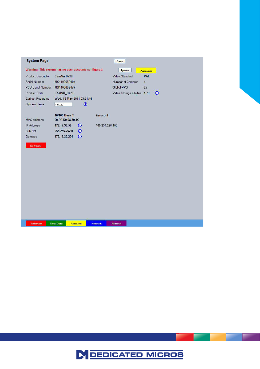
Attributes
This menu shows the general information about the unit including the version of software installed, the
unit’s serial number and the allocated DHCP IP address.
The system will display a warning if user accounts have not been set up. These can be eliminated by
setting up accounts in ‘Display->User Accounts’.
Installation Guide
Product Descriptor Details the product model.
Serial Number Identies the serial number of the specic unit.
PCB Serial Number Displays the PCB (Printed Circuit Board) serial number of the unit.
Product Code Displays a code identifying the unit’s specication.
Earliest Recording Displays the date/time of the earliest recording held on the unit.
System Name This eld can be edited to allocate a name to the unit, which can be
typed directly into a browser to access the conguration pages. This is
displayed when the unit is accessed via NetVu ObserVer and is sent
when transmitting information to a Remote Video Response
Centres (RVRC).
MAC Address This is the MAC address assigned to the unit.
IP Address These are the IP addresses allocated to the unit (zeroconf and interface
IP addresses are displayed in Closed IPTV operation)
Sub Net This is the subnet mask for the unit
Gateway This is the IP address of the default gateway (router) assigned by the
DHCP server.
15
Page 16
Number of Cameras Shows the number of camera channels on the unit i.e 1
Global PPS Details the unit Global PPS (Pictures Per Second) recording rate.
Video Storage Gbytes Highlights the available video storage capacity in Gigabytes.
Video Standard Displays the video standard adopted by the unit i.e. PAL, NTSC.
Software (Red) Links to the System Settings->Software details page
Time/Date (Green) Links to the System->Time and Date page
Accounts (Yellow) Links to the Viewer Settings->User Accounts details page
Network (Blue) Links to the Network Settings->Network details page
Refresh (Purple) Refreshes the current page
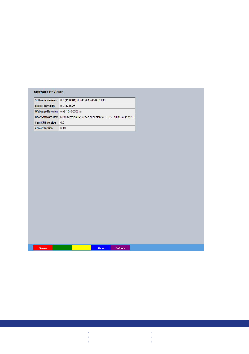
Software
This page details the installed software and may be needed if calling Technical Support.
16
System (Red) Links back to the System Setttings page
About (Blue) Opens the System->About page.
Refresh (Purple) Refreshes the current page
CamVu 720
Page 17
Status
Unit Status
This menu details information regarding the status of the unit, notably the total time the unit has been
operating and the time since its last reset.
Installation Guide
Time since last reset Details the time since the unit was last reset.
Total running time Details the total time the unit has been operational.
Reset code The last reset code used is displayed.
Restart reason The reason for the last restart is displayed i.e. Controlled
User Reset.
Refresh (Purple) Refreshes the current page
17
Page 18

About
This page provides quick links to the pages required to fault nd.
18
System Information Opens the System Settings->System page.
Software Revisions Opens the System Settings->Software page.
General Information Opens the General Information page (refer to ‘General Information’).
Record Details Opens the Record Details page (refer to ‘Record Details’).
Camcong Details Opens the Camcong Details page (refer to ‘Camcong Details’).
Capabilities Opens the Capabilities Details page (refer to ‘Capabilities Details’).
UI Information Opens the UI Information page (refer to ‘UI Information’).
Prole Record Tables Opens the Prole Record Tables page (refer to ‘Prole Record’).
Glossary Opens the Glossary page (refer to ‘Glossary’).
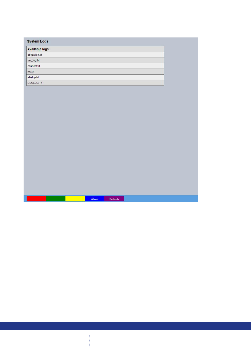
Logs
The log les stored in the unit can be accessed from this page. Selected logs are displayed on the page
below.
CamVu 720
Page 19
About (Blue) Select to open the System->Status->About page.
Refresh (Purple) Refreshes the information on the current page.
Installation Guide
19
Page 20
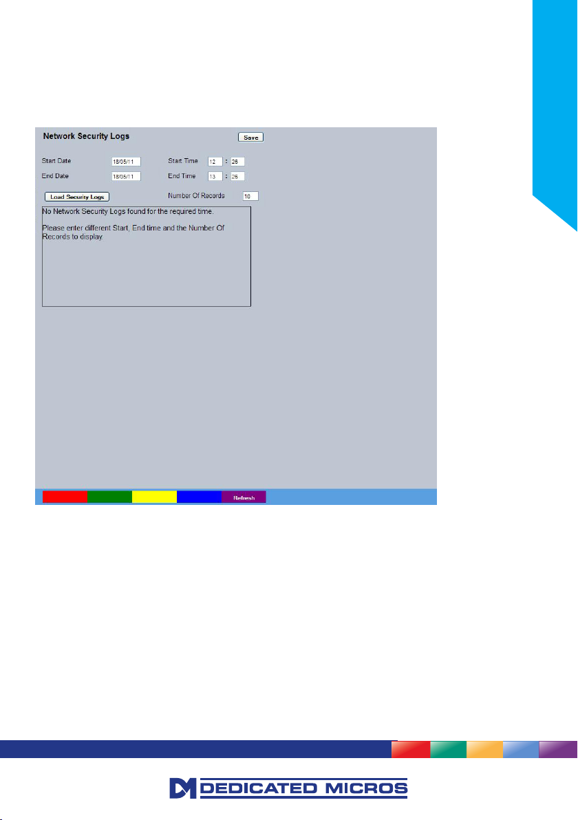
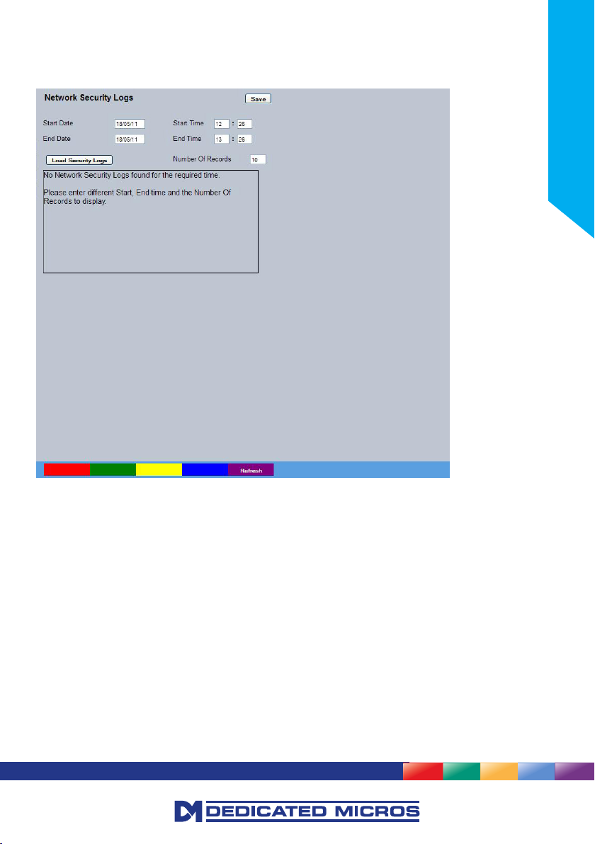
Network Security Logs
The log les stored in the camera can be accessed from this page. Selected logs are displayed on the
page below.
20
Start Date Enter a start date to lter the security log entries
Start Time Enter a start time to lter the security log entries
End Date Enter an end date to lter the security log entries
End Time Enter an end time date to lter the security log entries
Load Security logs Displays security events that were logged within the start and end
parameters
Refresh (Purple) Refreshes the current page
CamVu 720
Page 21
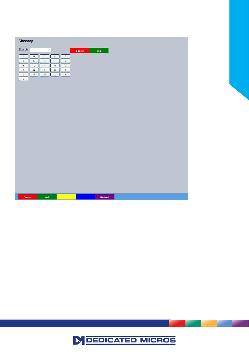
Glossary
This page provides quick reference to the technical terms used throughout the manuals and on the
conguration pages, and allows alphabetical indexing and free text searching.
Installation Guide
Search (Red) Enter text into the search box and then click this button to nd all
related terms.
A-Z (Green) Activates the letter selection buttons allowing all subjects within a
selected index letter to be displayed.
Refresh (Purple) Refreshes the current page
21
Page 22
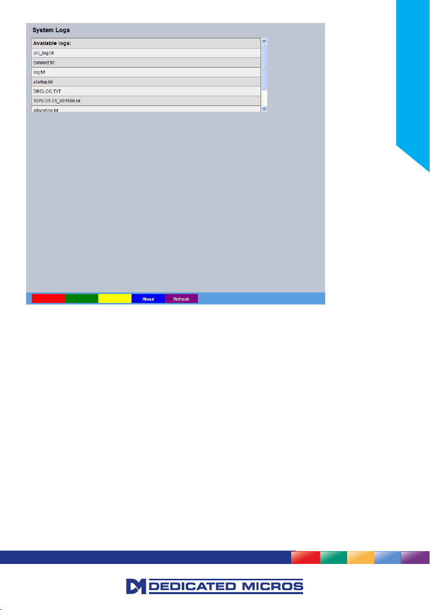
Logs
The log les stored in the camera can be accessed from this page. Selected logs are displayed on the
page below.
22
About (Blue) Opens the About page
Refresh (Purple) Refreshes the current page
CamVu 720
Page 23
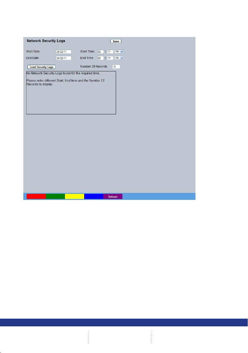
Security Logs
The network security logs, which show details of attempted intrusions over the network between the
congured dates and times, can be displayed on this page.
Installation Guide
Refresh (Purple) Refreshes the information on the current page.
23
Page 24
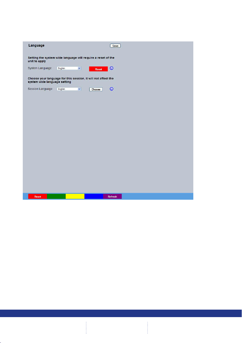
Language
This menu allows the system language to be set. Changing the System Language will effect all menu
pages. If required, the language can also be changed for the current session only.
24
System Language Select to change the system language setting.
Reset (Red) Select to reset the unit.
Note: The unit MUST be reset to implement system language changes, refer to
System Settings->Maintain for guidance on resetting the unit.
Session Language Select to change the language settings for the current
session only.
Choose Select to immediately activate session language changes.
Reset (Red) Select to cycle the power to the unit.
Refresh (Purple) Refreshes the information on the current page.
CamVu 720
Page 25
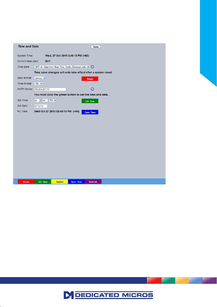
Time and Date
This menu allows the time and date to be set on the unit. Required timezone information can also be
established and the unit time synchronised to that of the PC being used to view the webpages.
IMPORTANT: Not all options will be available when the unit is operating in Analogue mode.
Installation Guide
System Time The current system time and date is displayed.
Current Time Zone Displays the currently selected time zone settings.
Time Format As default, the time displayed is in 12 hour format. This can be changed
to 24 hour if required.
Date Format As default, the date is entered dd/mm/yy. It can also be displayed as
mm/dd/yy or yy/mm/dd.
Set Time Enter a current time for the unit.
Set Date Enter a current date for the unit.
Set Time (Green) When current time/date as been entered, select this button to
implement changes.
Time Zone Select the relevant timezone offset from the accompanying drop down
menu.
SNTP Server A Simple Network Time Protocol (SNTP) server allows external devices
to connect and set their current date and time settings to that of the
SNTP. If required, enter the SNTP server IP address here.
25
Page 26

Note: It is recommended that an SNTP server is congured. Suitable networked SNTP servers can
be found here: http://support.ntp.org/bin/view/Servers/NTPPoolServers. Alternatively most
DHCP and DNS servers also run SNTP services. Contact your system administrator for further
assistance.
Note: The ‘SNTP Server’ option will not be available when the unit is operating in Analogue mode.
PC Time Displays the system time of the PC currently being used to view the
Sync Time (Blue) Use this button to synchronise the time of the unit to that of the PC
Note: The PC Time and Sync Time options will only be available if viewing the menu via
the webpages.
Reset (Red) Select to cycle the power to the unit.
Set Time (Green) When current time/date as been entered, select this button to
System (Yellow) Select to open the System->Attributes page.
Sync Time (Blue) Use this button to synchronise the time of the unit to that of the PC
Refresh (Purple) Refreshes the information on the current page.
webpages.
being used to view the webpages.
implement changes.
being used to view the webpages.
26
CamVu 720
Page 27
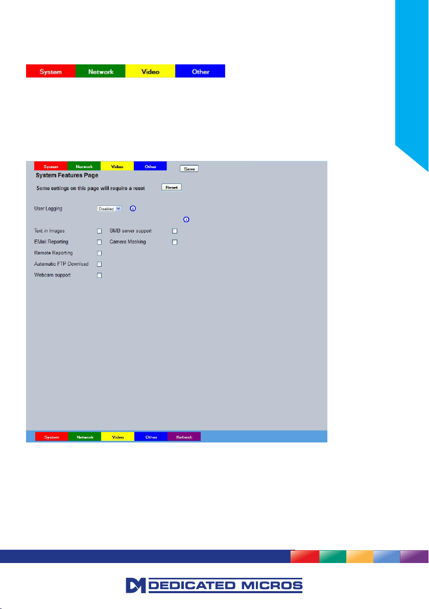
Features
This menu enables the activation of system features such as Email Reporting.
System (Red) Opens the System Features page
Network (Green) Opens the System Features Network page (below)
Video (Yellow) Opens the System Features Video page (below)
Other (Blue) Opens the System Features Other page (below)
Refresh (Purple) Refreshes the current page
System Features
Installation Guide
User Logging Enable this option to activate User Logging, refer to ‘Appendix A’ for
further information regarding the User Logging function.
Text in Images Select this option to activate the Text in Images function, refer to
‘Analytics & Text-Text In Image’ for more information.
Note: When de-selected here, the ‘Text in Image’ menu will no longer be displayed in the menu tree.
Email Reporting Select this option to activate the Email Reporting function, refer to
‘Network Settings-E-mail’ for more information.
Note: When de-selected here, the ‘Email Reporting’ menu will no longer be displayed in the menu tree.
Remote Reporting Select this option to activate the Remote Reporting function, refer to
27
Page 28

‘Network Settings-Remote Reporting’ for more information.
Note: When de-selected here, the ‘Remote Reporting’ menu will no longer be displayed in the menu
tree.
Automatic FTP Download Select this option to enable automatic FTP downloads to upgrade the
Note: When de-selected here, the ‘Automatic FTP Download’ menu will no longer be displayed in
the menu tree.
Webcam Support Select this option to activate the Webcam function. This allows the unit
Note: When de-selected here, the ‘Web Cam’ menu will no longer be displayed in the menu tree.
SMB Server Support Select this option to activate the SMB (Server Message Block) le
Camera Masking Select this option to activate the Camera Masking function, refer to
Note: When de-selected here, the ‘Masked Camera Detection’ menu will no longer be displayed in the
menu tree. Camera Masking
System (Red) Select to open the System->Features->System page
Network (Green) Select to open the System->Features->Network page
Video (Yellow) Select to open the System->Features->Video page
Other (Blue) Select to open the System->Features->Other page
Refresh (Purple) Refreshes the information on the current page.
unit and/or the webpages, refer to ‘Network->FTP Download’ for more
information.
to emulate a webcam and send image from one video feed in webcam
format, refer to ‘Network Settings->Web Cam’ for more information.
sharing function. When activated, the SMB protocol allows the unit
to access PCs operating the Windows operating system (and Linux
machines running Samba). This enables sharing of les and directories
to/from the unit. The name of the SMB Workgroup on the network
must be correctly entered in the SMB Workgroup option (see below).
It is important that the Server Name assigned to the unit via ‘Network
Settings->Server Name’ is unique within the workgroup being used.
To access the unit via a PC running SMB (and has access to the
same Workgroup); open My Network Places-Entire Network- Microsoft
Windows Network. The Workgroup containing the unit and PC(s)
should then be available. Files and folders can then be copied/added
as required.
‘Alarm Settings-Masked Cam Detection’ for more information.
28
CamVu 720
Page 29
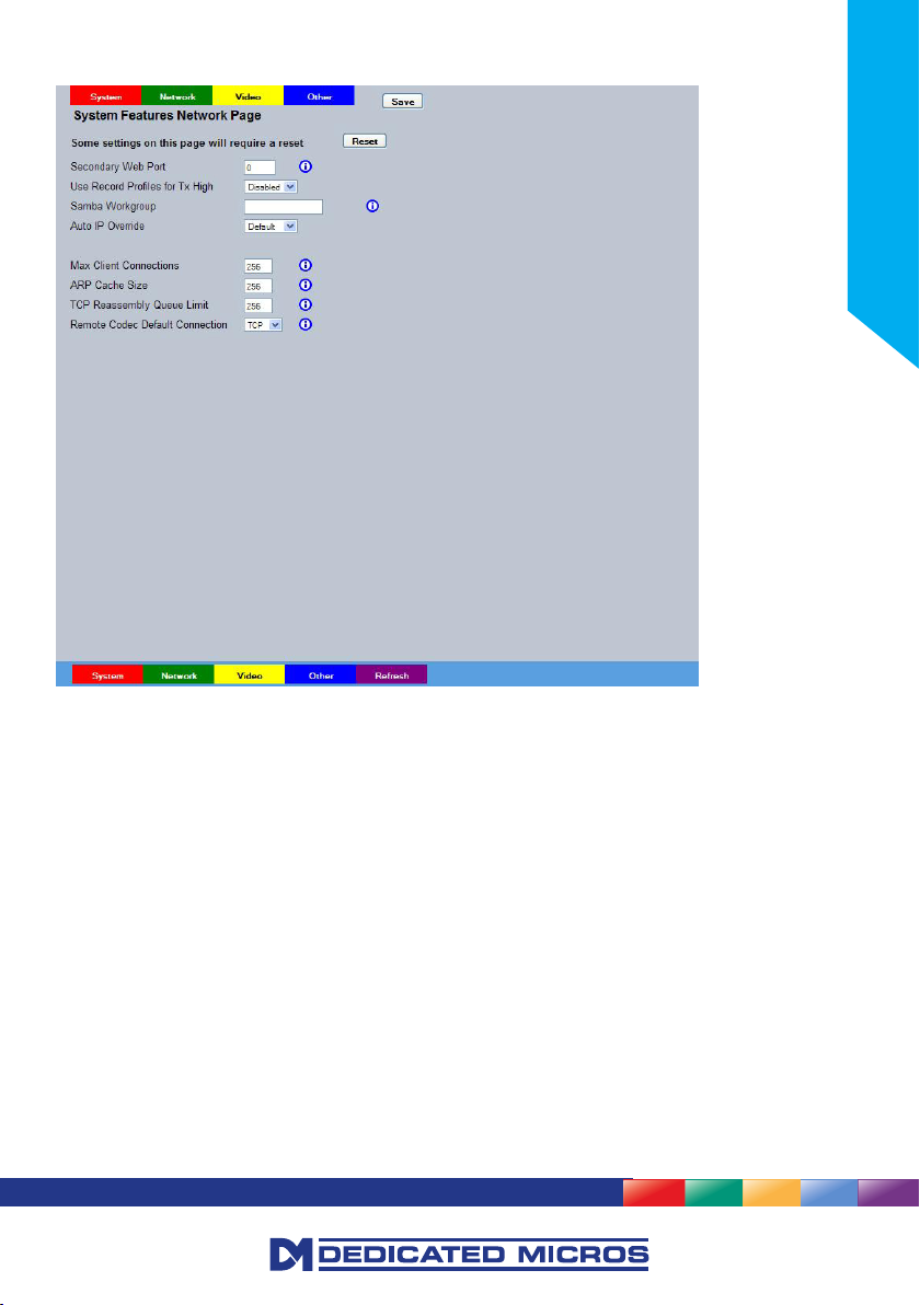
System Features Network
Installation Guide
Secondary Web Port If the default port setting for web serving has already been allocated,
it is possible to congure a second port number i.e. the secondary web
Use Record Proles for Tx High This option sets the Video Transmission prole for the ‘High’ setting
Auto IP Override This is defaulted to allow zero conguration at the factory. Select
Max Client Connections This setting limits the number of client connections to the server.
ARP Cache Size This setting limits the number of cache entries available in the ARP
TCP Reassembly Queue Limit This setting limits the maximum number of TCP segments allowed in
Remote Codec Default Connection
System (Red) Select to open the System->Features->System page
Network (Green) Select to open the System->Features->Network page
Video (Yellow) Select to open the System->Features->Video page
Other (Blue) Select to open the System->Features->Other page
port can be set to 8000 if the default web port (80) is blocked by the
network or rewall.
to be identical to the settings (rate/quality/resolution) that are being
recorded.
Disable to prevent Zero Cong address negotiation.
The default value is 256 but could be increased if there is heavy
network trafc.
table. The default setting of 256 is adequate for most instances
the reassembly queue, to protect against a common DoS attack.
This selects the initial connection type to use for an auto congured
remote codec camera, select from TCP or UDP
29
Page 30

Refresh (Purple) Refreshes the information on the current page.
System Features Video
30
Detected Video Standard
Analogue Output Resolution Allows selection of the resolution, options are 704 x 576, 704 x 512 and
Deinterlace Filter
3D Input Filter Advanced input ltering to the video codec, providing input signal
Segment Aspect Ratio This setting control how a 4:3 image is displayed in a multi-screen or
Network (Green) Select to open the System->Features->Network page
Video (Yellow) Select to open the System->Features->Video page
The unit automatically detects the video standard being used i.e. PAL/NTSC.
640 x 512
Select this option to improve display clarity and minimise the comb effect
that may be visible when recording high motion scenes in high resolution.
noise reduction. It’s primary purpose is to reduce noise observed when
viewing standard denition cameras or HD monitors. Options are Off,
Time Domain Filter, Spatial Filter, or Both.
wide screen format on the local viewer. The available display segment
changes depending on the number of multi screen images selected for
display. Stretch forces the image to ll the available display segment.
This may result in some distortion of the display image. Zoom Fit forces
the frame to ll the available segment completely and proportionally.
Consequently some of the image at the top and bottom of the frame
may be cropped. Frame Fit forces the frame to ll the available
segment proportionally, resulting in black bars left and right on some
multi display choices.
CamVu 720
Page 31

Other (Blue) Select to open the System->Features->Other page
Refresh (Purple) Refreshes the information on the current page.
System Features Other
Installation Guide
Auto Update Web Variables This is used to enable/disable the conguration webpage auto update
acceptance option which is displayed when the conguration webpage
version has been updated.
The default is to auto accept and update the conguration pages.
Enable Event Search Page Select to enable the Event Search option.
Note: When de-selected here, the ‘Event Search’ menu will no longer be displayed in the menu tree.
Enable RVRC page Select this option to activate the RVRC Remote Set/Unset/Override
function, refer to ‘Record Settings-RVRC’ for more information.
Note: When de-selected here, the ‘RVRC’ menu will no longer be displayed in the menu tree.
Network (Green) Select to open the System->Features->Network page
Video (Yellow) Select to open the System->Features->Video page
Other (Blue) Select to open the System->Features->Other page
Refresh (Purple) Refreshes the information on the current page.
31
Page 32

Maintain
This menu allows the unit to be reset and a software upgrade to be performed via an inserted CD-R/
DVD-R or a connected USB device. Current unit settings can also be saved for future use and previously
saved settings restored.
32
Conguration
Default (Green) Select to return the unit to its factory default settings.
Note: Selecting the Default button will cause the system to reboot.
Save (Purple) This button uses the select box and the to/from box. Select to save the
selected settings to the selected media.
Restore (Blue) This button uses the select box and the to/from box. Select to save the
selected settings to the selected media.
Note: Selecting the Restore button will cause the system to reboot.
select Select if the Cong or Licence les will be saved or restored.
To/From Select the relevant media device to save to or restore from i.e. USB or
CD-R/DVD-R.
Status A dynamic bar will indicate the progress made during any of the
conguration processes.
Export Logs
Export Logs (Yellow) Select to export all Logged data to a connected external device.
To Select the relevant media device to save to export to.
CamVu 720
Page 33

Server
Reset (Red) Select to cycle the power to the unit.
IMPORTANT: To upgrade the unit, insert a media device containing relevant software upgrades
and select ‘Reset‘.
Note: For the latest software upgrades, please refer to the Dedicated Micros website:
www.dedicatedmicros.com
Reset (Red) Select to cycle the power to the unit.
Default (Green) Select to return the unit to its factory default settings.
Export Logs (Yellow) Select to export all Logged data to a connected external device.
Restore (Blue) Select to restore previously saved settings from the selected media.
Save (Purple) Select to save current unit settings to the selected media.
Installation Guide
33
Page 34

PowerScript Mgmt
This menu enables installed PowerScripts to be activated/deactivated on start-up. Use the tickbox(es) to
select/deselect installed PowerScripts, then select Save (Green). A system reset will be required for the
changes to take affect.
34
Note: Changes this page will alter the ‘Default.C’ le. If you already have a custom PowerScript on your
unit which uses Default.C, please contact Dedicated Micros Technical Support for guidance Tel:
+44 (0) 845 600 9502 for further guidance.
Reset (Red) Select to cycle the power to the unit.
Save (Green) Updates the DEFAULT.C le on the NVR to enable selected scripts on
reboot.
Refresh (Purple) Refreshes the information on the current page.
CamVu 720
Page 35

Installation Guide
35
Page 36

Display
The Display menu allows settings for the local viewing client to be established and user access to the
system.
IMPORTANT: The Display menu will not be available when the unit is operating in Analogue mode.
The Viewer Defaults page allows the Viewer menu settings to be congured.
The User Accounts page helps protect conguration procedures by limiting access to specic users via
accounts and passwords.
36
CamVu 720
Page 37

Viewer Defaults
The units Viewer function allows remote users to simulate local operation over a network. This menu
allows conguration of settings for the Viewer function, refer to ‘Operating The Viewer’ for more
information regarding the Viewer.
Installation Guide
Default Image Format Images from cameras can be displayed in either JPEG or
MPEG format. Default settings can be congured for accessing the
Viewer function via a low bandwidth connection (WAN) or a higher
bandwidth connection (LAN).
Default Image Req Images displayed full screen in the Viewer menus can be shown
in either High Medium or Low resolution. Default settings can be
congured for accessing the Viewer function via a low bandwidth
connection (WAN) or a higher bandwidth connection (LAN).
37
Page 38

Applet Location The location of the unit’s Viewer menu applet is displayed. The default
Set Location Select the applet location. Choose from ‘Default location’ i.e. the
Reset (Red) This button will restart the unit.
Refresh (Purple) Refreshes the current page
location will always be the applet installed on the unit. If accessing
multiple units via a remote connection, all can be assigned the same
Viewer applet. This will lessen the load time required when accessing
different systems.
For example, if a local unit and a remote DVR are to be accessed, it is
possible to set the Applet location for both DVRs as the local unit.
If viewing the unit remotely, Dedicated Micros provide a remote applet
located on the Dedicated Micros website (www.dedicatedmicros.com/
software_release/windows/viewer-applet.jar). Due to possible bandwith
restrictions on the network the DVR is located, using this remote applet
may improve data transfer speeds.
applet installed on the unit; or the ‘Dedicated Micros website’
option i.e. the remote applet.
38
CamVu 720
Page 39

User Accounts
The unit can protect conguration, control FTP and viewing rights by limiting access via user names and
passwords.
Installation Guide
Account Types The available account types for which users and passwords can be
assigned privileges are:
• Admin FTP Assigning username and password
requirements for the Admin FTP function will
limit access to the unit via an FTP connection.
• Video FTP Assigning username and password
requirements for the Video FTP function will
limit access to the Video FTP archiving feature
(used with NetVu ObserVer).
• Telnet Assigning username and password
requirements for Telnet connections will limit
Telnet access to the unit (Telnet can be used to
upgrade the unit).
• Serial Assigning username and password
requirements for Serial connections will limit
access via a Serial link.
39
Page 40

• Menu Conguration Assigning Menu Conguration access privileges
• Local Users Assigning Local Users access privileges will
• Remote Users Assigning Remote Users access privileges will
When granting access privileges to Local and Remote Users, it is possible to limit access to specic
cameras. Using the Camera Selection segment of the Add New Account menu, enter those cameras
for which access will be permitted. Select the cameras in accordance with the input channel they’re
connected to on the rear of the unit. For example, if wanting to allow access to camera 1 to 3 inclusive,
enter: 1-3. If wanting to grant access to cameras 1,3 and 6, enter 1,3,6. If no camera data is entered,
access will be allowed to all connected cameras in both live and playback modes.
Note: There are no default usernames and passwords for any of the Account Types. If none are
assigned, access will be granted to all users and no request for a username and password will be
made.
Account List When an Account Type is highlighted, details of users with access will
be displayed.
Add Highlight an administration feature i.e. Serial and select ‘Add’. Enter the
new User Name and Password. That user’s name will now be displayed
in the account list.
Modify/Delete To modify or delete a user’s settings, highlight the user in the list and
press the relevant button to Modify or Delete.
IMPORTANT: If passwords are implemented and then forgotten, it is likely the unit will need to be
returned to Dedicated Micros for unlocking.
Add (Red) Highlight an administration feature i.e. Serial and select ‘Add’. Enter the
new User Name and Password. That user’s name will now be displayed
in the account list.
Modify (Green) To modify user setting, highlight the user in the list and press to Modify.
Delete (Yellow) To delete a user, highlight the user in the list and press to Delete.
Account Info (Blue) Select to display general information regarding the various
account types.
will limit access to the Conguration menus
when viewed locally. When implemented, the
user will be prompted for a username and
password before access to the Conguration
menus (via the main menu) will be granted.
limit access to the Viewer pages for local users.
When implemented, the local user will be
prompted for a username and password before
access to the Viewer pages (via the main
menu) will be granted.
limit access to the Viewer pages for remote
users. When implemented, the remote user
will be prompted for a username and password
before access to the Viewer pages (via the
main menu) will be granted.
40
CamVu 720
Page 41

Camera
The Camera menus allow conguration of the camera setup, refer to the individual menus for further
information.
The Setup page allows the quick conguration the camera setup.
The Iris Control page allows adjustments to settings of a DC drive lens when one is tted. This is to allow
for tolerances in manufacturers lenses.
Installation Guide
41
Page 42

Setup
This menu allows the conguration of local camera settings for the unit.
42
Camera Title This title can be edited to allocate a name to the unit. This is displayed
when the unit is accessed via NetVu ObserVer and is set when
transmitting information to a Remote Video Response
Centre (RVRC)
Lens Select Set the camera to support Manual Iris or DC Drive lens. Congure a
selected DC drive lens on the Iris Control page, refer to Camera->Iris
Control.
Exposure Time Exposure time defaults to 1/50 which prevents blurring of the recorded
image. For views containing high speed images, the setting can
be increased (to a max of 1/100 [PAL] or 1/120 [NTSC]). For views
containing static images, the setting can be decreased (to a min of 1)
Collection Res Setting the Max Collection Resolution limits the unit to record within the
selected maximum resolution. Lowering the resolution settings
will signicantly lessen the storage capacity requirements when
using Integrated Camera Recording. Available resolutions range
from CIF to UXGA.
Auto white balance Enables auto tracing white balance.
Electronic Iris Allows the camera to provide a electronic iris control if manual lens is
selected.
CamVu 720
Page 43

Exposure Level Sets the target exposure level that the electronic iris will try to attain.
This can be used to adjust the brightness of the image.
Flip Video Used to invert the image when the camera is mounted upside down.
Mirror Video Select to ‘mirror’ the camera image (horizontal ip).
Sharpness Manually adjust the image sharpness.
Decrement - (Green) Decrease sharpness
Increment + (Yellow) Increase Sharpness
Refresh (Purple) Refreshes the current page
Installation Guide
43
Page 44

Iris Control
This menu is for advanced use only. It is factory set and should not require any alteration.
Under normal operating conditions no adjustment is needed, however in certain circumstances benets
may be seen through minor adjustment for some DC drive lens.
44
Iris Response This will change the speed at which the Iris will respond to changes
in lighting conditions. The default is for a medium speed of response
however this can be set to react slower or faster to changes in the
scene as desirable to suit lens types and conditions.
Iris Offset Iris Offset is calibrated from the factory. However it may be necessary
to adjust this setting for different manufacturers lenses to allow for
differences in their specication. If the images from the camera are
pulsing in brightness, start by incrementing slowly until an improvement
is seen. If by doing this the pulsing is actually getting worse,decrement
instead to correct. If stability can not be reached then use the slower
Iris response setting.
Save (Red) Save the current settings.
Decrement - (Yellow) Use the button to reduce the zero crossing point setting by 1
Increment + (Blue) Use the button to increase the zero crossing point setting by 1
Refresh (Purple) Refreshes the current page
CamVu 720
Page 45

ICR Settings
The ICR Settings menus allow conguration of the unit’s record functions. ICR settings can be congured
for normal operation, on alarm, by schedule and for set holiday and weekend periods. Selected video data
can be saved and protected. Refer to the individual menus for further details.
IMPORTANT: The ICR Settings menu will not be available when the unit is operating in Analog mode.
The Default page allows the basic Recording settings to be edited.
The Prole Record page allows the recording conguration to be based on specic priorities. The record
rate and quality can be customised to respond appropriately to the alarms and time of day. A high degree
of control and exibility is possible using these options.
The Protect Video page allows previously recorded data to be protected and retained. If needed, all
recording can be halted and saved video deleted.
The AoE page allows conguration of the units ATA over Ethernet (AoE) function. AoE is a network
protocol designed for simple high-performance access of storage devices over Ethernet networks
Importantly the external storage device must be located on the same network as the unit.
The Video Storage page displays drives that are available for video recording and allows the formatting
and allocation of these devices.
Installation Guide
45
Page 46

Default
The unit has a range of pre-dened congurations available. As standard the unit can record at 5pps
MPEG4 and at a selected number of days. Alternatively the unit can be congured for 2pps JPEG
recording on each camera or for MultiMode operation (note that this will result in the record duration
being determined by the time period the unit is in alarm).
Note: This page is only relevant if images are being recorded to the camera. If a DVR is being used,
recording direct to the camera may be disabled.
46
Days
Recording Displays the record duration possible using the current conguration.
Timed Expiry (Days) If required, all stored recorded video can be permanently deleted after a
Camera Settings Choose the rate of non alarm recording to be used from the range
Record Duration/Enhance Quality The recording duration can be limited to a set number of days; allowing
Default All (Green) Restore record settings to factory defaults.
Refresh (Purple) Refreshes the current page.
set number of days. Set to ‘0’ to de-activate this function.
of preset recording proles. Select from Normal Rate-MPEG4 5pps,
Normal Rate-JPEG 1pps or Normal Rate-MultiMode recording.
the recording quality to be enhanced for a shorter storage period.
CamVu 720
Page 47

Prole Record
It is possible to set the unit recording conguration based on specic priorities. The MultiMode recording
feature offers the ability to set different recording rates, resolutions and compression formats across
unset, set and override modes for each individual camera. By varying the quality, bit rate and le size
of recorded images, the MultiMode function enables the recording capabilities of the unit to be greatly
increased.
Note: This page is only relevant if images are being recorded to the camera. If a DVR is being used,
recording direct to the camera may be disabled.
Simple Record
Installation Guide
Menu View Switch to the Advanced Prole Record menu.
Days Recording Displays the record duration possible using the current conguration.
Unset/Set/Override Normal Shows the recording prole used by the camera if no Timer Functions
are applied and the camera is operating under Normal (non Event)
conditions, refer to the ‘Schedules’ section for further details.
Unset/Set/Override Event Shows the recording quality that will be used by the camera during an
Alarm or Event. Note that Set and Override schedules will be used only
when Timed Schedules are applied, refer to the ‘Schedules’ section for
further details.
Note: Unset, Set and Override modes may be renamed via Record Settings->Schedule.
Comp Select image compression format (MPEG, JPEG or H264).
47
Page 48

PPS The accompanying dropdown list allows the number of frames captured
The pictures per second (pps) option allows either 6, 5, 2, 1, 0.5, 0.25
Pictures can also be recorded at 1/4, 1/2 or 3/4 Real Time.
To disable record, choose the ‘No Record’ option.
Select ‘User Dened’ to use settings established in the Advanced
Quality The accompanying dropdown list allows the quality of recorded images
Note: The higher the Quality setting, the greater the storage space needed.
Refresh (Purple) Refreshes the current page
per second to be set.
or 0.1 pps to be recorded.
Prole Record menu.
to be set. Select from Maximum, Very High, High, Medium, or Low.
Select User Dened to use settings established in the Advance Prole
Record menu.
48
CamVu 720
Page 49

Advanced Record
Installation Guide
Menu View Switch to the Simple Prole Record menu.
Note: When Advanced Record settings have been changed, it is not possible access the Simple
Record menu until the newly congured Advanced Record settings have been applied. To do this,
open the Record menu and select the ‘Save’ option. It will then be possible to return to the Prole
Record menu and access Simple Record.
Days Recording Displays the record duration possible using the current conguration.
Channel Displays the Camera Name.
Filter by Displays the Recording Settings.
Unset/Set/Override Normal Shows the recording prole used by the camera if no Timed Schedules
are applied and the camera is operating under Normal (non Event)
conditions, refer to ‘Schedule’ for further information.
Unset/Set/Override Event Shows the recording quality that will be used by the camera during
an Alarm or Event. Note that Set and Override schedules will be used
only when Timed Schedules are applied, refer to ‘Schedule’ for further
information.
Comp Select image compression format (MPEG, JPEG or H264).
Res Select image resolution format (HD720, XGA,SVGA, VGA, QVGA,
Q2VGA).
rate_kbps If MPEG4 is selected, the gure entered here will be the bit rate
allocated. A higher bit rate will provide better quality. MPEG bit rates
can be entered within the range of 45-2500K bits/second.
49
Page 50

Size If JPEG is selected, the gure entered here will be the size of the JPEG
PPS Select the number of pictures recorded per second.
GOP If using MPEG4 recording, select the number of images recorded within
Refresh (Purple) Refreshes the current page.
transmitted (in Kbytes). JPEG le sizes can be congured within the
range of 5-45Kbytes.
a GOP (Group of Pictures). A GOP consists of an I-Frame (keyframe)
and following P frames.
50
CamVu 720
Page 51

Protect Video
This menu allows the unit to automatically protect and retain recorded data in the camera. Previously
saved data can also be unprotected. Enter a start and end time and select ‘Reload List’ . All saved video
les from the chosen time period will be shown in the upper textbox. These recorded ‘PAR’ les can then
be selected and protected via their accompanying checkboxes and the Protect option. Selected video les
can also be unprotected via the Unprotect option.
The lower textbox provides a status report detailing which video les have been protected/unprotected.
Installation Guide
Start Date Enter a start date to protect video.
Start Time Enter a start time to protect video.
End Date Enter an end date to protect video.
End Time Enter an end time to protect video.
Protect Length (days) Enter the number of days that selected les will be protected for.
Protect Select this option to protect recorded video for the selected
time period(s).
Unprotect Select this option to unprotect recorded video selected from
the list.
Reload List This will refresh the video list according to the selections made in the
Start Time/Date and End Time/Date dialog boxes.
Select None This de-selects all the available video les.
Select All This selects all the available video les.
51
Page 52

List From Date/Time This dialog box allows a search to be made within the protected video
List To Date/Time This dialog box allows a search within the protected video list to
Unprot all (Red) Select to unprotect all recorded video from the list
Protect (Green) Select to protect recorded video for the chosen time period
Unprotect (Yellow) Select to unprotect recorded video for the chosen time period
Refresh (Purple) Refreshes the information on the current page
list starting from a specic Time and Date.
conclude at a specic Time and Date.
52
CamVu 720
Page 53

AoE
This menu allows conguration of the units ATA over Ethernet (AoE) function. AoE is a network protocol
designed for simple high-performance access of storage devices over Ethernet networks. Importantly the
external storage device must be located on the same network as the unit. AoE does not rely on network
layers such as IP and TCP, making it non routable i.e. routers cannot be used to forward a packet across
disparate networks. AoE packets can only travel within a single local Ethernet storage area network
(adds a physical layer of security to the information). The stored video can only be accessed by plugging
directly into an ethernet socket in the same LAN as the host. This means AoE cannot be accessed over
the Internet or other IP networks, but makes AoE more lightweight (with less load on the host), easier to
implement, provides a layer of inherent security, and offers higher performance.
Installation Guide
Logical Devices Connected AOE Devices - Any devices in this panel are being used by
the unit to store data. They can be freed by clicking on the
Release button.
Physical Devices Available AOE Devices - Any devices in this panel are available on the
network. They can be added to the storage capability of this unit by
‘claiming’ the storage. Unavailable storage is listed as Owned.Claimed
storage capacity can be ‘released’ in the top panel.
Refresh (Purple) Refreshes the current page.
53
Page 54

Video Storage
The Video Storage Allocation table displays drives that are available for video recording. Entries with the
prex ‘/HDD0’ indicate the units local hard drive (if installed), entries prexed by ‘/udd0’ are recordable
media connected to the unit via USB sockets (if tted), an entry prexed by ‘/mdd’ are installed SD cards.
54
Device Entries with the prex ‘/HDDx’ (from 0 upwards) indicate the units local
hard drives (if installed), entries prexed by ‘/uddx’ (from 0 upwards)
are recordable media connected to the unit via USB sockets, an entry
prexed by ‘/mdd0’ is the installed SD card. Subsequent MDDx entries
are for extra SD cards (where tted).
Size The device returns information when it is interrogated on connection to
the camera, the size of the recordable media is amongst this data.
Partitions The device returns information when it is interrogated on connection to
the camera, the number of partitions is amongst this data.
Allocate Formatted media can be allocated to the camera to allow it to be
used for recording. DM recommends that media is formatted before
allocation, even if if has been used previously for video storage.
Realm Displays the status of the associated media.
Feedback Displays messages about the progress of formatting/allocation of the
media.
Format (Red) Prepares the media for video storage, refer to ‘To format additional
Video Storage’.
Stop Rec (Yellow) Suspends Recording on the unit
CamVu 720
Page 55

Clear Video (Blue) Wipes the video from the drive to disable playback.
Refresh (Purple) Refreshes the current page
To format additional Video Storage
1. Plug a USB storage device into one of the available USB ports and click the purple Refresh
button. The newly connected device will be displayed with a ‘/UDD’ prex. The SD card (if
installed) will also be displayed and can be allocated in the same way. USB devices will be
prexed ‘/UDD’, SD cards will be prexed ‘/MDD’.
2. The device may require formatting. DM recommends the device is formatted even if it was
previously been used as video storage. Click on the ‘Format’ button adjacent to the device
listing to prepare the device for recording.
Installation Guide
3. Allocate the formatted and mounted storage for video storage by clicking on the ‘Allocate’
button. Allocation takes between a few seconds and a few minutes, depending on the size of
the drive, and the Feedback column will display information about the allocation process. The
unit will require a Reset once allocation is complete.
Note: The unit application drive is protected, if it is allocated the unit will only remove the video folder.
Formatting any other device will remove all data. In either case recording on the system is halted
while formatting and, if already allocated, the formatted device will be de-allocated as a video
storage device
55
Page 56

The system displays a conrmation box to ensure the correct device has been selected.
Click OK to conrm, then reboot the system. Once the power has cycled, the system will
build the required PAR les ready for recording to commence, progress will be displayed
Note: There will be a pause before recording begins, dependant on the size of the USB device as video
in the Feedback column.
partitions are built.
56
CamVu 720
Page 57

Schedule
This menu allows the Timer Function names to be congured. The Timer Function enables the unit
to automatically be put into set/unset mode at specic times on specic days. This can help reduce
unnecessary alarm triggers. The mode can be set by the DVR that the camera is connected to.
When the unit is in Set or Unset mode, combine with different recording qualities and rates under normal
and alarm conditions for a high degree of control in a range of situations.
IMPORTANT: The Schedule menus will not be available when the unit is operating in Analogue mode.
The Setup page allows conguration of the schedule including naming the modes of operation and
controlling when the unit changes between modes.
The RVRC page allows a user to temporarily switch the unit’s system state into set/unset/
override mode.
Installation Guide
57
Page 58

Setup
This menu allows the Schedule function to be congured. This enables the unit to automatically be put
into set/unset mode at specic times on specic days. This can help reduce unnecessary alarm triggers.
Combining when the unit is in Set or Unset mode with different recording qualities and rates under normal
and alarm conditions gives a high degree of control in a range of situations.
58
Mode/Title Enables a name to be entered for Unset, Set and Override mode.
Note: Any changes to Mode titles here will affect the mode names displayed in the Prole Record, IP
Record and Zone Input menu pages.
Current Mode Shows the current timer mode according to the names entered in the
Mode/Title text boxes.
Day Species which Day of the week is being congured
NOTE: The next two descriptions utilise the standard name settings for the proles (SET, UNSET).
If these names have been changed on this page, these menu options will display the user
congured names.
UNSET Time Species what time in format HH:MM the UNSET recording settings,
congured on the Prole Recording page, will become operational
SET Time Species what time in format HH:MM the SET recording settings,
congured on the Prole Recording page, will become operational
CamVu 720
Page 59

Note: The arrow button displayed next to each textbox allows settings to be replicated for those
cameras listed below. This will only affect the adjacent option i.e. Mode arrow will replicate the
Mode setting to all cameras below the clicked arrow.
Note: To disable one day, set both times to 00.00. To have the prole recording all 24 hours of a day,
set both times to 24.00
Refresh (Purple) Refreshes the current page.
Installation Guide
59
Page 60

RVRC
This menu allows a user to temporarily switch the unit’s system state into set/unset/override mode. The
user will be required to enter their name and also the intended override duration. The action will be
logged.
Note: Refer to the Schedule menu for details of how to congure Set, Unset and Override modes:
Record Settings->Schedule.
60
Current System Time The unit’s current date and time information will be displayed. This will
be logged with any override action.
System GMT offset in mins Shows the number of minutes between the time in the time zone
congured for the unit and GMT.
Current timezone Displays the congured time zone for this unit, as set on the System-
>Time and Date page.
Current PC Time The current date and time information of the PC currently being used
to view the webpages will be displayed. This will be logged with any
override action.
PC GMT offset in mins Shows the number of minutes between the time as congured on the
connected PC and GMT.
Current system state The current system state will be displayed i.e. Set, Unset or Override.
Note: The system state names displayed here will depend on those entered via the Schedule menu:
Record Settings->Schedule.
CamVu 720
Page 61

Override duration (minutes) Enter a time period for the override procedure. After this time period,
the system state will return to that congured via the Schedule menu
(for the current time).
Enter Your Name Enter your recognised user name. This will be logged.
Force UNSET(Green) Select to switch to Unset mode.
Force SET (Yellow) Select to switch to Set mode.
Force OVERRIDE (Blue) Select to switch to Override mode.
Refresh (Purple) Refreshes the information on the current page.
Installation Guide
61
Page 62

Alarm Settings
The Alarm Settings menus allow conguration of the unit’s alarm functionality. Individual alarm inputs and
alarm zones can be congured.
The Zone Input page enables the conguration of alarm zones. Up to 32 separate alarm zones can be
created.
The Zone Actions page enables actions such as Go to Preset to be allocated to alarm zones. Zones can
also be associated with a specic camera. On receipt of an alarm, images from the associated (primary)
camera will automatically be displayed in the Viewer menu.
The Alarm Response page enables conguration of responses following an VMD/Activity
Detection trigger.
The Activity page allowed activation and conguration of the Activity feature on all video inputs. The
Activity feature enables cameras to automatically detect any movement/changes within the video scene.
This can trigger a number of operations such as FTP alarm notication or an increase in the recording
rate.
The VMD page enables the unit’s VMD (Video Motion Detection) to be set-up. VMD allows a camera to
automatically detect if there is any movement/changes within specic areas of the video scene.
62
CamVu 720
Page 63

Zone Inputs
This menu allows the conguration of established alarm zones. A single or multiple trigger can be used
to generate an alarm. It is possible to allocate up to 32 alarm zones to carry out a combination of actions.
Use these options in conjunction with the Zone Actions menu.
Installation Guide
Entry timer This is the number of seconds allowed for the user to enter the zone
and disable the alarms. If the alarm is not disabled within this period the
alarm will be triggered.
Exit timer This is the number of seconds from the alarm being set within which the
user must exit the set zone. If the user is still within the zone after this
time period the alarm will be triggered.
Zone An alarm zone can be established to logically groups alarms and initiate
actions when an alarm is activated, there are 32 congurable zones.
Title This information is stored along with the relevant images in the
database, ensure this has relevance to the alarm zone.
Pre-Alarm sec. This is the time period prior to the start of the alarm included with the
alarm recording for archive. These images will also be protected from
being overwritten.
Note: It is recommended that the Pre-Alarm option be set to the same value as the Pre-Trigger setting
in the “Prole Record“ menu. This will ensure successful playback of high quality Pre-Trigger
images. High quality pre-trigger images will only playback properly if review (playback) starts
prior to the pre-trigger initiation.
63
Page 64

Alarm Protect sec. This is the minimum time period in seconds (from the start of the alarm)
Zone Input Rule This determines which input(s) will trigger the zone alarm:
Input This sets an input or system function as the primary alarm trigger.
Zone OR Input The Zone OR Input identies an alternative input that can also be used
Zone AND Input
Zone NOT Input
Alarm 24hr This option can be enabled for alarms that do not require change at any
Entry Route Zone This creates deferred alarms along a specied route while the
Exit route Zone This creates deferred alarms along a specied route while the exit time
Exit Terminator This will trigger the exit timer if the system is set. A countdown timer will
Entry Initiator This will trigger the entry timer if the system is set. A countdown timer
Enable in Unset Each alarm can be congured to be active when the unit is in a specic
Enable in Set Each alarm can be congured to be active when the unit is in a specic
Enable in Override Each alarm can be congured to be active when the unit is in a specic
Note: Unset, Set and Override modes can be given more recognisable titles i.e. Day, Night, Weekend
via the Schedule menu (Record Settings->Schedule).
Activity (Green) Select to open the Alarm->Activity menu
Zone Act (Yellow) Select to open the Alarm->Zone Actions menu
that is protected from being overwritten. This time will include the alarm
trigger, the pulse extension and any post alarm recording. It will not
include pre-alarm images.
Select from Disk Low, Disk Full, Panic, Archiving Slow, Archiving Fault,
Virtual 1-16, and Keyword Channel 1 (which will trigger the Alarm if any
of the programmed keywords are detected).
to trigger the zone alarm. This means an alarm trigger can be received
on the Zone Alarm Input or the Zone OR Input for the zone to be
activated.
The Zone AND Input identies that an alarm trigger needs to be
received on both the Zone Alarm Input and the Zone AND Input for
the zone to be activated and the alarm action to the
automatically initiated.
The unit will only issue the alarm actions if the trigger is received on the
zone alarm input and NOT on the Zone input.
time and are to remain as programmed i.e. Panic Alarm. When this is
selected, the Set, Unset and Override options are disabled.
entry time is active. This is in compliance with BS8418 (the British
Standard for remote video reporting centres). Diverting from the entry
route during the countdown will result in the alarm being triggered
immediately. This allows staff entry without triggering an alarm prior to
switching the system to Unset mode.
is active. This is in compliance with BS8418 (the British Standard for
remote video reporting centres). Diverting from the exit route during
the countdown will result in the alarm being triggered immediately. This
allows staff to exit without triggering an alarm.
automatically start when the alarm is activated and ensure the alarm
system is not activated by other specied alarm triggers for the Set time
i.e. allowing a Guard to exit a building.
will automatically start when the ‘primary’ alarm trigger i.e. front door,
is actioned. This ensures the alarm system is not activated by other
specied alarm triggers for the set time
operation mode. Enable this for the zone alarm to be active in Unset
operation mode.
operation mode. Enable this for the zone alarm to be active in Set
operation mode.
operation mode. Enable this for the zone alarm to be active in Override
operation mode.
64
CamVu 720
Page 65

Alarm in (Blue) Select to open the Alarm->Inputs menu
Refresh (Purple) Refreshes the information on the current page
Installation Guide
65
Page 66

Zone Actions
This menu allows actions to be allocated to individual alarm zones; Primary and Secondary cameras
can be allocated to the zone and actions undertaken following alarm activation. This page should be
congured in conjunction with the Zone Inputs menu.
66
Zone Select a zone (alarm) to congure.
Alarm Colour This displays the local alarm text in the selected colour and can be
Primary Camera This allows a camera to be assigned as the primary camera associated
Create Database Entry An alarm activation will be added to the database. The zone title will be
Alarm Reporting This must be enabled to allow the unit to send an alarm notication to
Add Still Image This will record a still image of the trigger along with the standard
Protect Alarm Images
Prole Change Select to enable the unit to switch from Normal to Event recording
Archive Select to ensure the unit automatically downloads alarm images via an
useful in prioritising alarms. Options available are Red, Green, Blue,
Yellow, Cyan and Magenta.
with the Alarm Zone. The primary camera will be displayed when an
alarm in this zone is triggered.
used as part of the entry information.
an external destination i.e. an RVRC reporting via NetVu ObserVer.
recording. This can then be sent on to an external destination.
Alarm images can automatically be protected from being overwritten
following alarm zone activation.
FTP connection to an FTP server.
.
CamVu 720
Page 67

E-mail Image If this option is selected, a JPEG will be added to the reporting e-mail (if
E-mail Reporting is selected).
VMD/Activity Inhibit Select to inhibit (ignore) the VMD/Activity detection feature. for further
information, refer to ‘Alarm Settings->Activity Setup’.
E-mail Reporting The unit can send an e-mail when an alarm is detected. For further
information, refer to ‘Network->E-mail’.
Relays (Blue) Select to open the Alarm->Global Actions menu
Refresh (Purple) Refreshes the information on the current page
Installation Guide
67
Page 68

Alarm Response
This menu enables response conguration following activity trigger on the camera channel.
68
VMD Pulse Extension The pulse extension extends the trigger period to avoid double triggers
Channel Select the camera input for conguration from the drop down list.
Detection Type Each camera input can be congured for either ‘VMD’ or ‘Activity’
Note: Whichever Detection option is selected here, will result in the camera channel being only
available for editing in the relevant conguration menu i.e. if Activity is selected
be edited for Detection in the Activity Setup menu and not the VMD Conguration menu.
Activity To Trigger Following Activity activation, select ‘Simple Response’ to trigger specic
Note: When Activity to Trigger is set to ‘Zone’; the options detailed below are unavailable.
Create Database Entry When selected, an alarm entry will be added to the Event database.
Prole Change Select to enable the unit to switch from Normal to Event recording
of VMD occurring, i.e. If a second incident of VMD is received, after the
rst alarm is nished but within this period, the unit will not create a new
event.
detection. To assign no detection settings to the camera, select ‘None’
; this channel can only
chosen responses from the options detailed below. Select ‘Zone’ to
apply the Zone Input rules as congured in the Zone Input menu, refer
to ‘Zone Input’ for more information.
following alarm activation.
CamVu 720
Page 69

Alarm Reporting This must be enabled for the unit to automatically connect
on alarm.
Alarm 24hr This will ensure that Activity Detection is permanently enabled on this
camera channel.
Add Still Image This will record a still image of the trigger along with the standard
recording. This can then be sent on to an external destination.
Protect Alarm Images Select to automatically protect alarm images from
being overwritten.
Alarm Relay This will trigger the unit’s on-board relay following VMD/Activity
activation.
E-Mail Image This will email a still image (in JPEG format) of the VMD/Activity trigger
to the email recipient as congured in the ‘E-mail’ menu (Network
Settings->E-mail)
Enable in Unset This will enable Activity Detection when the unit is in Unset
operation mode.
Enable in Set This will enable Activity Detection when the unit is in Set
operation mode.
Enable in Override This will enable Activity Detection when the unit is in Override operation
mode.
Note: Unset, Set and Override modes can be given more recognisable titles i.e. Day, Night, Weekend via the
Schedule menu (Record Settings->Schedule).
Refresh (Purple) Refreshes the information on the current page
Installation Guide
69
Page 70

Activity
The unit supports Activity Detection to enable the camera to automatically detect any movement/changes
within the video scene; this can trigger a number of operations such as FTP alarm notication and an
increase in recording rate. A still image of the selected camera will be shown in the Grid Editor screen. To
establish an Activity zone, edit the cells displayed across the image.
This option should be used in conjunction with the Zone Inputs and Zone Actions menus.
70
Global Activity Mode Select ‘Always Active’ for Activity mode to be in constant operation.
Activity Channel Displays the images from the corresponding video source.
Activity Sensitivity This option allows the sensitivity setting to be established for the activity
grid being congured. There are ve settings to choose from: Indoor
High, Indoor Low, Outdoor High, Outdoor Low, Very Low.
Grid Editor Use the Grid Editor by placing cells in areas of the camera view where
movement will trigger an alarm by clicking the mouse on the grid cells
to enable/disable.
Reload Img (Red) This option will update the still image displayed in the Grid Editor.
Set All (Green) This option will insert a default square of 16 x 16 cells across the
displayed video image.
Clear All (Yellow) This option will clear all entered cells.
Refresh (Purple) Refreshes the current page.
CamVu 720
Page 71

VMD Conguration
The unit supports VMD (Video Motion Detection) on all video inputs and allows cameras to automatically
detect if there is any movement/changes within the video scene.
Note: Video Motion Detection enables a greater degree of control over detection settings and
conguration than the Activity Setup function. Each of the 16 VMD Zones can be directly sized
and congured to suit specic requirements. VMD can only be accessed and congured remotely
via the webpages.
Installation Guide
Camera This is a drop down list of the video inputs on the unit, selecting one
of the inputs will display the corresponding video source. Ensure this
corresponds with the selected Channel.
Zone There are 16 VMD zones within the image that can be individually
congured, select the zone from the drop down list.
A selected zone can be re-sized by clicking the mouse button (use the
USB mouse if viewing on a local monitor) and then moving and clicking
the mouse again. A rectangle will then be displayed based on these two
selected points.
71
Page 72

Mode The zone mode controls when the reference image is taken for
Pixel Count (%) This value is set as a percentage and equates to the percentage of
Pixel Change (%) This setting is a percentage value of the overall change required in the
Global Activity Mode Three options are available for Activity activation (specically in relation
Reload Image (Red) This will update the reference image to the latest view during
Clear All (Green) Removes all dened zones from the image.
Default Grid (Yellow) Displays the default 16 zone grid across the whole image.
Refresh (Purple) Refreshes the information on the current page.
triggering VMD. The options are:
Normal - The reference image is updated approximately
every second. This will only allow small changes in
the scene without triggering.
Last trigger - The reference image is only updated when the
VMD is triggered and is best used under controlled
lighting, i.e so there are no false triggers due to
ambient light changes.
Static - The reference image is collected on startup and is
never updated. This would be used in ‘sterile’ areas
where there are no changes expected.
Zone disabled - This will disable the zone mode.
pixels in the selected zone that must change for the VMD event to be
triggered. The default setting is 20%.
grayscale to be included in the pixel count. The percentage change is
dened over the complete range of black to white, a 100% pixel change
would be from black to peak white. The default setting is 20%.
to a PTZ camera).
Selecting ‘Active while at Preset 1’ will result in Activity mode
functioning only when the camera is at preset position 1. Select ‘Active
while camera not in motion’ for Activity mode to function only when the
camera is still. Select ‘Always Active’ for Activity mode to be in constant
operation.
set up.
72
CamVu 720
Page 73

Network Settings
The Network Settings menus allow conguration of the unit’s network functionality. Key network settings
can be established such as ‘xing’ the unit’s IP address and maximum transmission rate. Email, remote
reporting on alarm and FTP download can also be congured. Refer to the individual menus for further
details.
The Network page allows conguration of the unit’s network connections such as the name assigned to
the unit and its IP address.
The Live Trans(mission) page enables JPEG and MPEG proles to be created for transmitting images via
a High, Medium or Low quality network connections to any viewing software or to another unit using this
one as an IP source.
The Multicast page allows recordings from the unit’s camera input to be forwarded to a port address;
enabling multiple viewers to view live data using a suitable media player without the need to directly
connect to the unit.
The Email page allows conguration of the Email feature. The unit can automatically transmit an e-mail to
an SMTP Server following an event i.e. on receipt of an alarm or a camera failure notice.
The Remote Reporting page allows a Remote Video Receiving Centre’s (RVRC) conguration details to
be entered. The RVRC will then be contacted following a selected event occurring i.e. reported alarm or
camera failure.
The Web Cam page allows the video input to be made available for transmission to a webserver via a
designated webcam server. The image can then be incorporated into a web page and accessed via a
standard web browser.
The FTP Download page allows data to be archived to a central FTP server. This could be on receipt of
an alarm, Activity activation or at a scheduled time to back-up recorded video.
The Firewall page allows conguration of the onboard rewall.
The Connections page displays the current live connections to the unit.
Installation Guide
73
Page 74

Network
This menu allows network settings to be congured if required. The unit is DNS compliant, and can
be referenced on the network using the congured server name (or serial number) if a DNS server is
available .
74
Server Name This eld can be edited to allocate a name to the unit. This would be used if
accessing the unit via a Domain Name Server (DNS).It will initially default to
the serial number of the unit.
IP Address An IP address can be manually allocated to the unit.
Sub Net A Subnet address of the unit network can be manually allocated.
Gateway This is the IP address of the default gateway (router).
Primary DNS This is the primary DNS server IP address for applications utilising
domain names.
DHCP If DHCP is being utilised, the assigned IP address will be
displayed here.
Note: If no IP address is manually congured, DHCP will automatically assign one. The unit interrogates the
network for a DHCP server, which assigns an available IP address. This IP address can change every
time the unit is powered up. If DNS is not available, it is recommended that DHCP be disabled by
entering a suitable, free, static IP address.
CamVu 720
Page 75

Tip: Use DHCP to locate a free IP address, then x the unit IP address to the free one by entering the details
into the IP address, subnet and gateway elds.
Max Transmission Rate kbits/sec This shows the maximum transmission speed for the network type
being used. If set to ‘0’, transmission speed is not limited in the camera.
Note: This setting will limit and override any higher transmission rate entered in the Video Transmission
menu (Conguration menu->Live Trans).
Force 10BaseT operation The unit supports 10 or 100BaseT half duplex transmission. Selecting
this option will force the unit to operate at a 10BaseT connection.
Tx Image Buffers This is used in order to improve the picture delivery over Ethernet when
using a slow connection i.e. 256Kbps. A buffer setting of 1,2 or 3 is
available (default setting is 1).
Ethernet MTU Bytes This is the maximum transmit unit for the Ethernet packet. The MTU is
the largest physical packet size measured in bytes that the network can
transmit. By default this gure is set to 1500bytes.
Max Transmission Timeout ms This is the time (in milliseconds) the unit will wait to re-send a packet if
an acknowledgement is not received.
Reset (Red) Resets the unit to apply changes.
Rem Report (Green) Opens the Network Settings->Remote Reporting page.
Webcam (Yellow) Opens the Network Settings->Web Camera Conguration page.
Email (Blue) Opens the Network Settings->Email page.
Refresh (Purple) Refreshes the current page.
Installation Guide
75
Page 76

Live Trans
The unit transmits live images using JPEG or MPEG formats.
The NetVu ObserVer remote viewing software will use the settings congured on this page as the defaults
for JPEG & MPEG; High, Medium and Low settings.
76
Filter by This will lter the camera category being edited. The resolutions
Note: The Megapixel Resolution option will only be available if a megapixel camera is connected.
IMPORTANT: There are three classications of IP camera:
1. Standard Resolution - QCIF,CIF,2CIF,4CIF
2. Standard Resolution (VGA) - VGA,SVGA,QVGA,Q2VGA
3. Megapixel - VGA,SVGA,UXGA,QVGA,Q2VGA,XGA,XGA+,SXGA+,QXGA
The classication of each connected camera channel can be viewed via the CamCong menu (System
Settings->Status->About->CamCong).
High LAN/Medium WAN/Low VLBR This shows the transmission settings congured for a High quality
available for selection will depend on the connected camera type (i.e.
Standard or Megapixel Resolution) and whether Turbo Mode has
been activated via the Prole Record menu (Record Settings->Prole
Record).
LAN (Local Area Network) connection, Medium quality WAN (Wide
Area Network) connection or a Low quality VLBR (Very Low Bit Rate
connection).
CamVu 720
Page 77

IMPORTANT: When ‘Filter by Turbo mode’ as been selected; all High LAN options will be auto-
Comp Settings can be established for JPEG and MPEG compression
Res
Size_rate For JPEG, the gure entered will be the size of the JPEG transmitted
PPS This shows the number of pictures transmitted per second.
MPEG Type Select whether transmitted MPEG4 images are sent as RAW data or in
MPEG Quality The Quality of the MPEG data transmission can be set from CBR
I Frame Ratio Select the number of I Frames recorded between each P Frame
Note: An MPEG I-frame is considerably larger than a P-frame. The higher the IP ratio, the larger the
Turbo Prefs (Red) Select to open the Turbo Mode Prole Overview menu, refer to
Refresh (Purple) Refreshes the information on the current page
congured to match the prole record settings allowing for maximum record
performance. High LAN will no longer be available for conguration of local analogue
cameras or third party IP cameras. Select the Turbo Profs (red) option to view Turbo
mode Prole Record/Transmission settings.
.
For MPEG and JPEG transmission, select image resolution settings
(4CIF, 2CIF, CIF or QCIF).
(in Kbytes). For MPEG4 the gure will be the bit rate allocated. A higher
rate will provide better quality picture display. JPEG le sizes can be
congured in the range of 5-45Kbytes and MPEG bit rates in the range
of 45-2500Kbits/second.
For JPEG,
the actual images transmitted will depend on the bandwith of the link,
increasing the pictures sent per millisecond may introduce time lag
if bandwith is not sufcient. On MPEG transmission, increasing the
pictures sent will also reduce the quality of the images (as more images
are transmitted for the dened bit rate).
GOV (Group of Video) format. RAW mode transmits a single I frame
and then a sequence of P frames (until a change in transmission is
detected). GOV mode sends I and P frames in a standard format i.e. I
to P frame ratio as set by the I Frame Ratio option (below).
(Constant Bit Rate) to High 32. A higher quality setting may result in a
lower transfer speed.
.
disk space required to store recorded images.
Appendix J - Status Pages for more information.
Installation Guide
77
Page 78

Multicast
The Multicast page allows video from the unit’s camera inputs to be forwarded to a port address, enabling
multiple viewers to view live data using a suitable media player without the need to directly connect to
the unit. In multi viewing scenarios, the demands on the unit are signicantly reduced, improving overall
performance.
This system has been validated using the ‘Videolan VLC media player for MS Windows.
The Videolan VLC media player can be downloaded free of charge from:
www.videolan.org/vlc/download-windows.html
Please refer to Appendix F for guidance on conguring the Videolan VLC media player.
Note: Multicast can only used for live viewing, requests for stored images and events will still need to
be made via the Viewer menu.
78
Separate IP for each camera Select to transmit each camera with a different multicast address and
the default port number.
Multicast Address Assign a unique IP address. This address is not assigned to any
‘physical’ unit. The VLC program will use this address (when congured
to do so) as its multicast group and access any broadcast images via
the congured port address (see below).
If there are multiple units using multicast, each one must have a unique
IP address.
CamVu 720
Page 79

Multicast port Following conguration of the IP address, congure the port address.
The address will default to 1234.
Multicast Method Select the multicast forwarding method. Select from ‘SAP’ (to use
session announcement protocol operation), ‘HTTP’ (to use cgi control
operation) or ‘SAP+HTTP’ (both methods used simultaneously).
Enable Tick this option to enable multicast.
TTL (Time to Live) This option can be congured to limit which users can access the
images. Enter one of the following numbers:
0 - restricts video to the same host
1 - restricts video to the same subnet
32 - restricts video to the same site
64 - restricts video to the same region
128 - restricts video to the same continent
255 - is unrestricted in scope
Refresh (Purple) Refreshes the information on the current page
Installation Guide
79
Page 80

The unit can automatically transmit an email to an SMTP server under numerous conditions i.e. on
start up, on receipt of an alarm, camera failure etc. This allows the unit to be installed in unmanned
applications where a Remote Video Response Centre (or Manager etc.) would be notied by email if any
of these conditions occur.
Note: This menu will only be displayed if ‘EMail Reporting’ is selected in the
System -> Features -> System menu.
80
Connection Prole It is possible for the email to be transmitted via the Ethernet network.
Mail Server Address This is the IP address or URL of the SMTP Server that the email will
Username Enter the login details for the email account used above.
Password Enter the login details for the email account used above.
Recipient Email This is the email address of the intended recipient.
Recipient Display Name
Reply to Email This eld must be congured if the recipient is to reply to an email. The
Reply To Display Name This is the ‘reply to’ name that will be shown in the email name eld.
This setting presumes that the unit is connected to a LAN or WAN and
allocated a valid IP address.
be sent to. The SMTP server will then forward this to the intended
recipient.
This is the addressee name that will be shown in the email name eld.
unit does not accept incoming emails therefore ensure this is a valid
email address.
CamVu 720
Page 81

Sender Email These optional elds indicate the source of the email notication. If the
elds are left blank the unit will use the system name to create a sender
name.
Sender Display Name This is the sender name that will be shown in the email name eld.
Send on Startup Select to send email notication on startup.
Send on Alarms Select to send email notication on alarm activation.
Send on Camera Fail Select to send email notication on camera fail.
Send on Activity Event Select to send email notication on activation of the Activity Detection
feature.
Send Image Select to send the image from congured primary camera associated
with the triggering alarm.
Email Image Res Select the resolution settings for the image sent as an attachment in the
Email. Choose from: Thumbnail, LO (low res), MED (medium res) and
HI (high res).
Log Email Select this to add every email transaction that the unit issues to the
email log.
Test Email (Red) Select to send a test Email to congured recipient
Zone Act (Green) Select to open the Alarm->Zone Actions menu
Network (Yellow) Select to open the Network->Network menu
Rem Report (Blue) Select to open the Network->Remote Reporting menu
Refresh (Purple) Refreshes the information on the current page
Installation Guide
81
Page 82

Remote Reporting
This menu allows conguration of the settings to enable the unit to report to a Remote Video Receiving
Centre (RVRC) following alarm activation.
Note: This menu will only be displayed if ‘Remote Reporting’ is selected in the
System -> Features -> System menu.
82
Primary Hostname This is the IP address or URL of the initial host that the unit will transmit
Primary Dial Prole It is possible for the alarm message to be transmitted via the Ethernet
Secondary Hostname If the unit is unable to contact the primary host, an alternative route can
Secondary Dial Prole
Public (NAT) Address This is the public IP (or domain name) for a unit connected to the
Video Server Port This eld allows the RVRC to connect to the unit through a router that
an alarm message to.
network or a dial up connection.
be identied via a secondary host. If there is only one alarm receiving
IP address, you must enter the same details in both the primary and
secondary connection settings.
It is possible to select a separate dial prole for the secondary host.
Internet via a NAT Router or Firewall. This eld should be left blank if
NAT is not used e.g. a private network.
is using port forwarding e.g. if the video server does not appear on port
80 (HTTP), to the external network. Enter the port number used for
forwarding here if required.
CamVu 720
Page 83

Alarm Server ref. ID This is the reference name/ID that will be presented to the RVRC
Remote Alarm Reporting
Remote Cam Fail Reporting Enabling this option ensures the unit reports camera failure on any of
Remote Startup Reporting This will send an alarm report when the unit starts up. Any system
ARC Ping Enabled
Alarm Responder Port This species the network port number used for reporting to the alarm
Dial Retry Time (secs) If the initial connection attempt fails, the unit will wait for the specied
Dial Count This species the number of times the unit will attempt to connect after
Zone Act (Green) Select to open the Alarm->Zone Actions menu
Network (Yellow) Select to open the Network->Network menu
Email (Blue) Select to open the Network->E-mail menu
Refresh (Purple) Refreshes the information on the current page
viewing application. It should therefore have some signicance to the
Operator.
This must be enabled for the unit to automatically connect on alarm.
the inputs to the RVRC.
resets will be identied.
Should the modem/router at the Alarm Receiving Centre be dormant, the
unit will ‘Ping’ the ARC prior to sending reporting data.
server. In normal circumstances this should be left at the default value
(23).
time period (in seconds) before attempting to re-connect.
a failed attempt. A setting of ‘0’ means no limit and the unit will continue
to try and connect until successful.
Installation Guide
83
Page 84

Web Cam
Any of the video inputs on the unit can be made available for transmission to a webserver via a
designated webcam server. These images can then be incorporated into a web page and accessed via a
standard web browser.
Note: This menu will only be displayed if ‘Webcam Support’ is selected in the
System -> Features -> System menu.
84
Server URL This is the IP address, URL or Domain Name of the webcam server.
Images will be uploaded from the unit to this server at specied time
intervals.
Disable ICMP Discovery When enabled, the unit will not attempt to ‘Ping’ the congured web
server but will begin immediate data transfer.
Root Directory This is the main/root directory on the webcam server where the image
directory will be located.
Image Directory This directory will be created when the initial image is uploaded to the
webcam server, it is the directory where all images will be saved on the
server.
Image Filename Prex This is an identier for images sent from the unit and will be
stored as a prex to the le name.
Username If it is necessary to use an authentication process to access the
webcam server, enter the relevant username here.
CamVu 720
Page 85

Password If it is necessary to use an authentication process to access the
webcam server, enter the relevant password here.
Update Interval This is howoften the unit transmits images to the web server.
Select Camera Input This allows individual video inputs to be enabled for uploading to the
webcam server.
Webcam Enable The Web Cam function can be: ‘Always Enabled’, ‘Enabled when
system SET’, ‘Enabled when system UNSET’ or ‘Disabled’.
Webcam Resolution Select a High, Medium or Low webcam resolution settings.
Network (Blue) Select to open the Network->Network menu
Refresh (Purple) Refreshes the information on the current page
Installation Guide
85
Page 86

FTP Download
The unit can archive images to a central FTP (File Transfer Protocol) server. This could be on receipt
of an alarm, activation of the Activity Detection or at a scheduled time to backup recorded video. Using
FTP in a multi-unit application ensures that all les are stored in one central location for each of the units,
offering efcient le management and easy review capabilities.
Note: This menu will only be displayed if ‘Automatic FTP Download’ is selected in the
System -> Features -> Network menu.
86
Current Status
Last Doanload Status
FTP Server URL or name This is the IP address, URL or name of the FTP server the unit will
connect to for FTP image download purposes.
FTP Control Port Default 21 The default port for FTP use is port 21. If this port has already been
allocated on the network, it is possible to identify and allocate an
alternative port.
Status Server Port Default 23 The default port for the Server Status function is port 23, if this port
has already been allocated on the network, it is possible to identify and
allocate an alternative port number.
FTP Root Drive and Directory This is the directory where the images are to be stored, it is
recommended that a name associated with the unit be used for ease of
retrieval.
CamVu 720
Page 87

Username If it is necessary to use an authentication process to access the FTP
server, enter the relevant username here.
Password If it is necessary to use an authentication process to access the FTP
server, enter the relevant password here.
Download options Select one of the following options from the drop down menu:
On Connection This will automatically start the Archive download when
the unit detects the archive destination is present.
Scheduled It is possible to force the unit to archive images at a
scheduled time, enter a time to activate this function
each day.
Polled This will set the unit to activate archive download at
regular intervals, the time is in minutes and is the
period between the end of one archive download and
the start of the next.
Manual only The archive process will only commence when the user
initiates the action.
Schedule time hh mm If ‘Scheduled’ has been selected in Download Options, enter a time for
the download to take place each day.
Poll time Minutes If ‘Polled’ has been selected in Download Options, enter the number
of minutes which will elapse between the conclusion of one archive
download and the start of the next.
FTP Download overrides recording
Watermark each partition This enables a watermark to be generated and stored in a text le
downloaded with the video to the FTP server (for each image partition).
This watermark is logged in the log le.
Clear video protection
after download This automatically clears the image protection from successfully
downloaded images.
Start Dload (Red) Initiates the download process
Refresh (Purple) Refreshes the information on the current page
Installation Guide
87
Page 88

Firewall
This menu allows the user to block access to the unit via specic network port(s).
88
Enable Ping Response Enabling this option will allow an external client to receive a response
when attempting to ‘ping’ the unit. Disabling this option will make the
unit less visible on the network.
Service Name Up to 32 Conguration settings may be entered.
Port Start / Port End Enter a start and end point for the ‘open’ port range. If a host tries to
communicate with the unit using a TCP/UDP port that is not within the
‘open’ range (even with a valid IP address), access will not be granted
to the unit. The enabled ports can be a range or single port address, if a
single port is needed then enter the same port number in the Start and
End options.
Type Select either TCP or UDP port types.
Open Select to open (enable) the congured port range.
By IP (Green) Select to open the Firewall Access by IP menu
Refresh (Purple) Refreshes the information on the current page
CamVu 720
Page 89

Connections
This page shows the IP addresses of users connected to this unit. It is for information only and cannot be
edited or congured.
Installation Guide
Refresh (Purple) Refreshes the current page
89
Page 90

Features & Text
The Features and Text menus allow activation of the units analytics and third party IP camera features
plus conguration of the unit’s text in image and keywords functionality. Refer to the individual menus for
further details.
The unit is AnalyticsCapable. Please call Dedicated Micros on + 44 (0) 845 600 9500 for further
information on our range of Analytics based solutions.
The Text In Image page allows the unit to integrate text data with recorded images i.e. a cash register with
a camera positioned at the point of sale.
The Keyword page can be used in conjunction with the Text in Image function. Keywords can be entered,
which when detected, will trigger an alarm. Up to 30 keywords can be created.
90
CamVu 720
Page 91

Features
Dedicated Micros has created a range of analytics components and solutions designed to work with
AnalyticsCapable products. The range of applications include: Automatic Number Plate Recognition
(ANPR), Object Left and Removed, Access Control, People Counting and Perimeter Protection.
Installation Guide
• For further information regarding the range of Dedicated Micros Analytics solutions,
please call: + 44 (0) 845 600 9500
91
Page 92

Activate New Feature
The Activate New Feature menu allows new AnalyticsCapable licenses to be added to your unit and
the Third Party IP Camera feature to be unlocked. It details the Features System Code that Dedicated
Micros Customer Services require to provide the Activation Code. Also detailed are all advanced features
currently activated on the unit (and the maximum number of each type of
license allowed).
IMPORTANT: To open the ‘Activate New Feature’ menu, navigate to the Features &
Text->Features menu and select the Activate (Purple) option.
92
Currently Active Features Any advanced features currently installed on the unit will be detailed
here.
Type The available variants of feature licenses will be listed.
In Use The total number of each license type currently installed on the unit will
be displayed.
Maximum This shows the maximum amount of each license type that can be
installed on the unit.
Note: AnalyticsCapable licenses are purchased per unit, with the exception of ANPR licenses which
are per camera channel.
Features System Code This code must be provided to the Dedicated Micros Customer
Services team (Tel +44 (0) 845 600 9501) to obtain your Activation
code. On receipt of this information, DM will provide you with your
Activation code.
CamVu 720
Page 93

License Key Enter the License key details here. The License key will be provided by
Dedicated Micros Customer Services team.
Activation Code Enter the Activation Code details here.
Note: Both the License Key and Activation Code are case sensitive. Be careful to differentiate between
number ‘0’ and letter ‘O’.
Note: Navigate to System Settings->PowerScript Mgmt to view DM PowerScript software currently
active on your unit (and limit which scripts will automatically run at start-up). When any
AnalyticsCapable licenses have been activated, the ‘analytics.c’ option must remain checked for
the feature(s) to operate correctly.
To view the PowerScript Mgmt page it is necessary to install and run webpage software release
version 1.0 (2285) or above. The latest software release for your unit can be downloaded from
the Dedicated Micros website:
www.dedicatedmicros.com/software_release/index_rmware.php
IMPORTANT: For AnalyticsCapable features to function correctly, the ‘Enable Keyword’ function must
be enabled on the unit. Navigate to the ‘System Settings->Features’ menu and ensure
the ‘Text In Image’ option is selected. Then navigate to the ‘Features & Text->Text In
Image’ menu. Set the Enable Keywords option to ‘Enable’.
Reset (Red) Select to reset the unit.
Refresh (Purple) Refreshes the information on the current page
Installation Guide
93
Page 94

Text In Image
It is possible to integrate the unit into a system were text information can be stored with relevant images
for review. This would be most useful in a Retail or Finance application were text data originating from a
cash register could be displayed in real time with the video images of the same Point of Sale.
Note:
This menu will only be displayed if ‘Text in Image’ is selected in the System Settings->Features menu.
94
Recorded lines per frame This controls how many lines of text are stored on the server, and not
how many are displayed on screen. This allows more data to be saved
than is shown.
Recorded characters per line Controls the width of the lines displayed on screen.
Text Timeout This setting controls how long, in seconds, the text is shown onscreen
(selecting 0 will show the text indenitely).
Channel Select the camera input for conguration from the drop down list.
Text Port Type Select the input source for Text in Image data. Select ‘Off’ to switch the
function off or ‘Network to use the unit’s Network port
Text Filter Select the text lter option from the drop down list. The options are:
Plain Text (default), RAW, EPSON, Laserjet, DM POS Receipt, DM
POS Journal, TVC-1066
Reset Resets the unit to apply changes.
Zone Act (Green) Opens the Alarm Settings -> Zone Actions page.
Keywords (Yellow) Opens the Features & Text -> Text -> Keywords page.
Refresh (Purple) Refreshes the current page
CamVu 720
Page 95

Installation Guide
95
Page 96

96
CamVu 720
Page 97

Installation Guide
97
Page 98

98
CamVu 720
Page 99

Installation Guide
99
Page 100

100
CamVu 720
 Loading...