

Page 1
Dedicated Micros Ltd.
11 Oak Street, Swinton,
Manchester. M27 4FL,
United Kingdom
Tel: +44 (0) 161 727 3200
Fax: +44 (0) 161 727 3300
Dedicated Micros Europe
Neckarstraße 15, 41836 Hückelhoven,
9-13 rue du Moulinet, 75013 Paris
14434 Albemarle Point Place, Suite 100,
Chantilly, Virginia 20151 USA
Freephone: 800 864 7539 Tel: +1 703 904 7738
23456 Hawthorne Blvd. Suite 100,
Dedicated Micros, Australia PTY.
5/3 Packard Avenue, Castle Hill,
Dedicated Micros, Asia PTY
#03-03 Hudson Techno Centre,
Dedicated Micros Middle East
P.O. Box 500291, Dubai Internet City,
Dedicated Micros (Malta) Ltd.
UB2 San Gwann Industrial Estate,
Germany
Tel: +49 2433 5258-0
Fax: +49 2433 5258-10
DM France
Tel:+33(0)145819999
Fax:+33(0)145819989
Dubai, United Arab Emirates
San Gwann SGN 09 Malta
France
Dedicated Micros USA.
Fax: +1 703 904 7743
Torrance, CA 90505, USA
Tel: +1 310 791-8666
Fax: +1 310 791-9877
NSW 2154, Australia
Tel: +612 9634 4211
Fax: +612 9634 4811
16 New Industrial Road,
Singapore 536204
Tel: +65 62858982
Fax: +65 62858646
Building 12, Suite 302,
Tel: +971 (4) 390 1015
Fax: +971 (4) 390 8655
Tel: +356 21483 673
Fax: +356 21449 170
English
485 Bus Alarm Module
Owners Guide for Setup & Operation
www.dedicatedmicros.com
MI-I-CI01/E1-0
Ó Dedicated Micros, October 2004
Page 2

Page 3
English
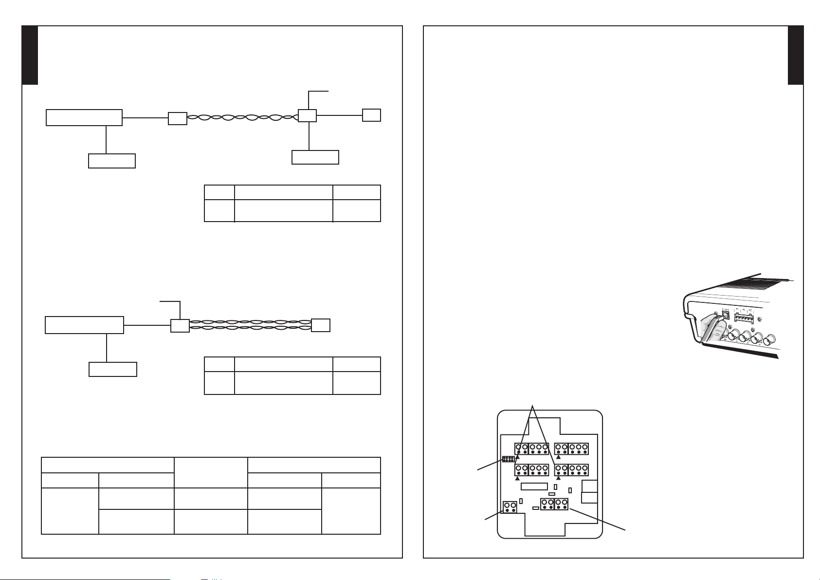
Remote connections via twisted pair plus keyboard and Jumper Link Settings
The diagram shows how to extend the distance of the alarm module using UTP Cat 5 cable plus the inclusion
of a remote keyboard. The keyboard can not connect to the alarm module so to provide connectivity for both
devices it is necessary to include a junction box (CJ01). The junction box requires a 12V supply,.refer to the
Junction Box manual for wiring details
MUX/DVR/DV-IP
3 Meter cable
3 Meter cable
Local Keyboard
CJ01
UTP Cat 5
Single pair
(Max 1500m/4500ft)
LINK
J4
FUNCTION
Route PWR IN to P4, for
remotely powered operation
CJ01
3 Meter cable
Local Keyboard
Remote
12V PSU
3 Meter cable
FITTED
Remote power via twisted pair and Jumper Link Settings
The diagram shows how power can be transferred across the UTP Cat 5 cable to power the remote alarm
module, this is if local power (to the alarm module) can not be achieved.
Local
12V PSU
MUX/DVR/DV-IP
3 Meter cable
3 Meter cable
CJ01
UTP Cat 5
Two pairs - Data and Power
(Max 100m/300ft)
CI01 alarm
module
CI01 alarm
module
POSITION
Introduction
The remote alarm module allows additional alarms to be connected to a Dedicated Micros multiplexer, DVR
and DV-IP product.
The additional alarm inputs are configured within the system menus and allows integration of building
management systems into a single solution, ensuring the site is continuously monitored and recorded (if
enabled).
Compatible DM Products
The CI01 alarm module can be included in installation that have one, or more, of the following DM products:
485 enabled Multiplexers
h
DS2 range
h
BX2 range
h
DV-IP range
h
Installation
The alarm module allows additional alarms to be integrated into a single monitoring solution additional alarms
can be connected to the screw terminal connectors in the module.
The screw terminal can be removed from the module to allow ease of installation. Once all additional alarms are
connected the screw terminal are simply plugged back into the module.
and connector table below
Ensure the connectors are placed back in the module in the correct location.
Note:
.
For pin details refer to the layout diagram
Connecting the Alarm Module to the Multiplexer
The alarm module connects to the DM multiplexer/DVR/DV-IP product via the 485 bus
connection on the rear of the unit.
Using the 485 bus cable provided (3 Meters) connect one end to the module
and the other to either of the 485 bus connectors on the unit.
If an alarm module is to be fitted remotely to the system and the
Note:
distance exceeds the 3 meter limit a 12V external supply is required to
power the alarm module.
English
POSITION
FITTED
Local Keyboard
LINK
J4
FUNCTION
Route PWR IN to P4, for
remotely powered operation
UTP CAT 5 Wiring Details
This shows the connections when using twisted pair.
LOCAL JUNCTION BOX
CONNECTOR CONNECTOR
P4
PIN PIN
Pin 1 +12V
Pin 4 GND
Pin 2 ‘A’ 485 Bus Data
Pin 3 ‘B’ 485 Bus Data
TWISTED PAIR
Pair 1
Pair 2
REMOTE ALARM MODULE
Pin 1 +12V
Pin 4 GND
Pin 2 ‘A’ 485 Bus Data
Pin 3 ‘B’ 485 Bus Data
P4
Key to Alarm Module
Connectors
(P2, P3, P5, P6)
ABCD
GND
Address
Links (J2)
Local 12V
power supply (P1)
J2
GND
P1
Alarm
P3
A1 A2 A3 A4 A5
P2
IC3
J5
J3
J4
GND B A +12V
P4
P6
A6
A7
A8
GND
P5
A13A9
A14A10
A15A11
A16A12
GND
MMJ
J6
P8
J7
MMJ
P7
Remote Power /
twisted pair data
transmission (P4)
Page 4

English
Jumper Link Information
There are a number of jumpers on the PCB,the following details the connector, function and default setting for
each jumper.
Link
Connection
J2
Pins1to8
J3
Pins1&2
J4
Pins1&2
J5
Pins1&2
J6
Pins1&2
J7
Not Fitted
Connector Information
The following details the functions of the multiple connectors on the PCB.
Connector
P1
P1
P2
P2
P3
P3
P4
P4
P4
P4
P5
P5
P6
P6
Function
485 Bus Address ( )
RESET
Route power in to P4, power board from P4
485 Bus Termination
NOT USED
Not Fitted
Connection
1
2
1
2to5
1
2to5
1
2
3
4
1
2to5
1
2to5
refer to address table below
Function
PWR IN GND
PWR IN +12V
Alarm input GND
Alarm inputs 9 to 12
Alarm input GND
Alarm inputs 1 to 4
Line Power 12V
485 Bus Data A/485 POS
485 bus Data B / 485 NEG
Line power 0V
Alarm input GND
Alarm inputs 13 to 16
Alarm input GND
Alarm inputs 5 to 8
Default
OFF (Default Address Module 1)
OFF
OFF
OFF
ON/OFF
N/A
Assigning the Address Link (J2)
Refer to the following table when changing the address of the 485 Bus alarm module from the default Module 01.
(See relevant multiplexer manual for more details).
Alarm
Module
1
2
3
4
5
6
7
8
9
10
11
12
13
14
15
16
Status of Link Settings
1&2
3&4
A
0
0
0
0
0
0
0
0
1
1
1
1
1
1
1
1
B
0
0
0
0
1
1
1
1
0
0
0
0
1
1
1
1
5&6
C
0
0
1
1
0
0
1
1
0
0
1
1
0
0
1
1
7&8
D
0
1
0
1
0
1
0
1
0
1
0
1
0
1
0
1
Address
096
097
098
099
100
101
102
103
104
105
106
107
108
109
110
111
A
B
C
D
Default setting
Module 1 (096)
Layout Diagrams
The following block diagrams show how the CI01 alarm module can fit into various scenarios.
Local connection and Jumper Link Settings
The diagram shows the alarm module connected directly to the unit using the 3 meter 485 bus cable (supplied). It
may be necessary to change the jumper links on the unit to ensure the power is routed correctly.
MUX/DVR/DV-IP
3 Meter cable
Local Keyboard
Remote connections via twisted pair with local power and Jumper Link Settings
The diagram shows how to extend the distance of the alarm module using UTP Cat 5 cable. The alarm module
requires a 12V supply.
MUX/DVR/DV-IP
3 Meter cable
3 Meter cable
3 Meter cable
CI01 alarm
module
CJ01
CJ01 junction
box
LINK
J4
FUNCTION
Route PWR IN to P4, for
remotely powered operation
UTP Cat 5
Single pair
CI01 alarm
module
POSITION
NOT FITTED
12V PSU
Pin 1 = GND
Pin 2 = +12V
English
P1
Local Keyboard
LINK
J4
FUNCTION
Route PWR IN to P4, for
remotely powered operation
POSITION
FITTED
 Loading...