

Page 1
Setup Guide
Guide d'installation
Setup-Anleitung
Guía de programación
Guida per l'impostazione
Page 2

Page 3

ENGLISH
1
Introduction
What is Digital Sprite Lite?
Digital Sprite Lite is an easy to use, cost effective video multiplexer, digital video
recorder, with optional network transmission in one box.
A video multiplexer?
• Designed with security in mind
• Easy to use
• Operates like a traditional analogue multiplexer, not a PC
• All the features you would expect from a Dedicated Micros multiplexer:
- Main and Spot monitor
- Multiscreen displays
- Activity detection
- Alarms
- Scheduling
- Variable record rates
- c-bus networking
A digital video recorder?
• Playback and record simultaneously, without affecting recording.
• Up to 14 days of 24-hour time-lapse recordings in the box.
• Instant access to images recorded onto the hard disk.
• No tapes required.
Network transmission?
• View live and playback images from Digital Sprite Lite across a network.
• No extra software to buy, uses Microsoft IE5 or Netscape Navigator 4.7.
• Telemetry control.
Page 4

✔
Remote Keyboard Control (optional)
Remote keyboard compatible ✔
Control of multiple units ✔
Telemetry Controller ✔
Network viewing (optional)
Live viewing ✔
Playback viewing ✔
Telemetry control ✔
Microsoft IE5 and Netscape Navigator 4.7 compatible ✔
External storage devices
Zip
®
✔
Jaz
®
✔
RAID ✔
Hewlett Packard DDS and Ecrix VXA Tapes ✔
To make the installation and operation as simple as possible this installation guide
has three sections:
1. Installing Digital Sprite Lite
- guiding you through the installation process
2. Configuring Digital Sprite Lite
- giving details of setting up the unit for the customer’s needs
3. Operating Digital Sprite Lite
- a card which can be removed from this manual provides a guide to
operating Digital Sprite Lite
Page 5

ENGLISH
3
Regulatory Notes FCC and DOC Information
(USA and Canadian Models Only)
Warning: This equipment has been tested and found to comply with the limits
for a Class A digital device, pursuant to part 15 of the FCC rules. These limits are
designed to provide reasonable protection against harmful interference when the
equipment is operated in a commercial environment. This equipment generates,
uses, and can radiate radio frequency energy and, if not installed and used in
accordance with the instruction manual, may cause harmful interference to radio
communications. Operation of this equipment in a residential area is likely to
cause harmful interference in which case the user will be required to correct the
interference at their own expense.
If necessary, the user should consult the dealer or an experienced radio/television
technician for corrective action. The user may find the following booklet prepared
by the Federal Communications Commission helpful: “How to Identify and
Resolve Radio-TV Interference Problems”.
This booklet is available from the US Government Printing Office, Washington,
DC20402, Stock No. 004-000-00345-4.
This reminder is provided to call the CATV system installer’s attention to Art.
820-40 of the NEC that provides guidelines for proper grounding and, in
particular, specifies that the cable ground shall be connected to the grounding
system of the building, as close to the point of cable entry as practical.
CE Mark
This product is marked with the CE symbol and indicates compliance
with all applicable directives.
Directive 89/336/EEC.
A “Declaration of Conformity” is held at Dedicated Micros Ltd.,
11 Oak Street, Swinton, Manchester M27 4FL.
Page 6

A quick overview of digital recording
Digital multiplex recorders work in exactly the same way as analogue multiplexers
except that they use hard disks and digital tape to store video, instead of VCR tapes.
Analogue recording uses time-lapse recording to extend the length of time
recorded onto a 3-hour tape - recording fewer pictures every second.
Adjusting the number of pictures recorded every second also extends the length
of time recorded onto the hard disk of a Digital Sprite Lite. However, other factors
also determine the amount of time that can be stored on the disk of a digital
multiplex recorder:
• The image quality
• The record rate
• The hard disk capacity
Image quality
Digital multiplex recorders store images in a compressed format, allowing images
to be recorded more efficiently. The higher the compression, the smaller the file
size, but the image quality will suffer. Digital Sprite Lite can compress images from
between 6KB to 30KB
Kilobytes and gigabytes are units of storage:
1GB = 1024 Megabytes (MB)
1MB = 1024 Kilobytes (KB)
With analogue recording, the image quality is dependent on the type of VCR
being used; VHS or S-VHS. Digital Sprite Lite allows the image quality to be
altered by adjusting the image size, for example, VHS quality is 14KB, S-VHS is
18KB, and greater than S-VHS is 25KB.
Using a larger image size will fill the hard disk faster than a smaller image size, as
more space is required to store it. To achieve the same amount of recording time
when a larger image size is used requires the record rate (PPS) to be reduced.
Page 7

ENGLISH
5
Digital Sprite Lite can be installed in as little as 4 steps, and being plug-and-play,
cameras can be recorded within minutes.
STEP 1. Connect cameras
Connect cameras to the video inputs marked VID1 to VID9 (9-way unit) or VID16
(16-way unit). Use the bottom row of connectors for looping through to other equipment.
STEP 2. Connect monitors
Connect the video output marked MON A to the Main monitor (digital playback
and multiscreens).
Connect the video output marked MON B to the optional Spot monitor (analogue
full-screen images).
STEP 3. Connect the external devices
If external devices need to be connected to Digital Sprite Lite, go to the next
section – ‘Connecting external devices’, before proceeding to Step 4.
STEP 4. Connect power
Once the Digital Sprite Lite is in its final position and all external devices have
been fitted and powered, connect the PSU to the rear of the unit and apply the
power. The power-up procedure may take up to one minute before Digital Sprite
Lite can be used.
will now record all cameras in a 24-hour time-lapse mode
without any further programming!
cameras
main monitor
RJ-45 ethernet
connection
S-Video main monitor
RS-485/RS-232 connector
SCSI-2 connector
spot monitor
loopthrough
AUX IN
-+
Quick install
Page 8
Serial telemetry
Digital Sprite Lite currently supports serial telemetry for JVC and Ultrak domes. Serial
telemetry requires a twisted-pair connection from Digital Sprite Lite’s serial port to
the telemetry receiver. Serial telemetry can be star configured – from the Digital
Sprite Lite serial port to each receiver, or delta configured – each receiver daisy
chained together, or a combination of the two. Each receiver needs to be addressed
according to its camera number – consult your receiver documentation for details.
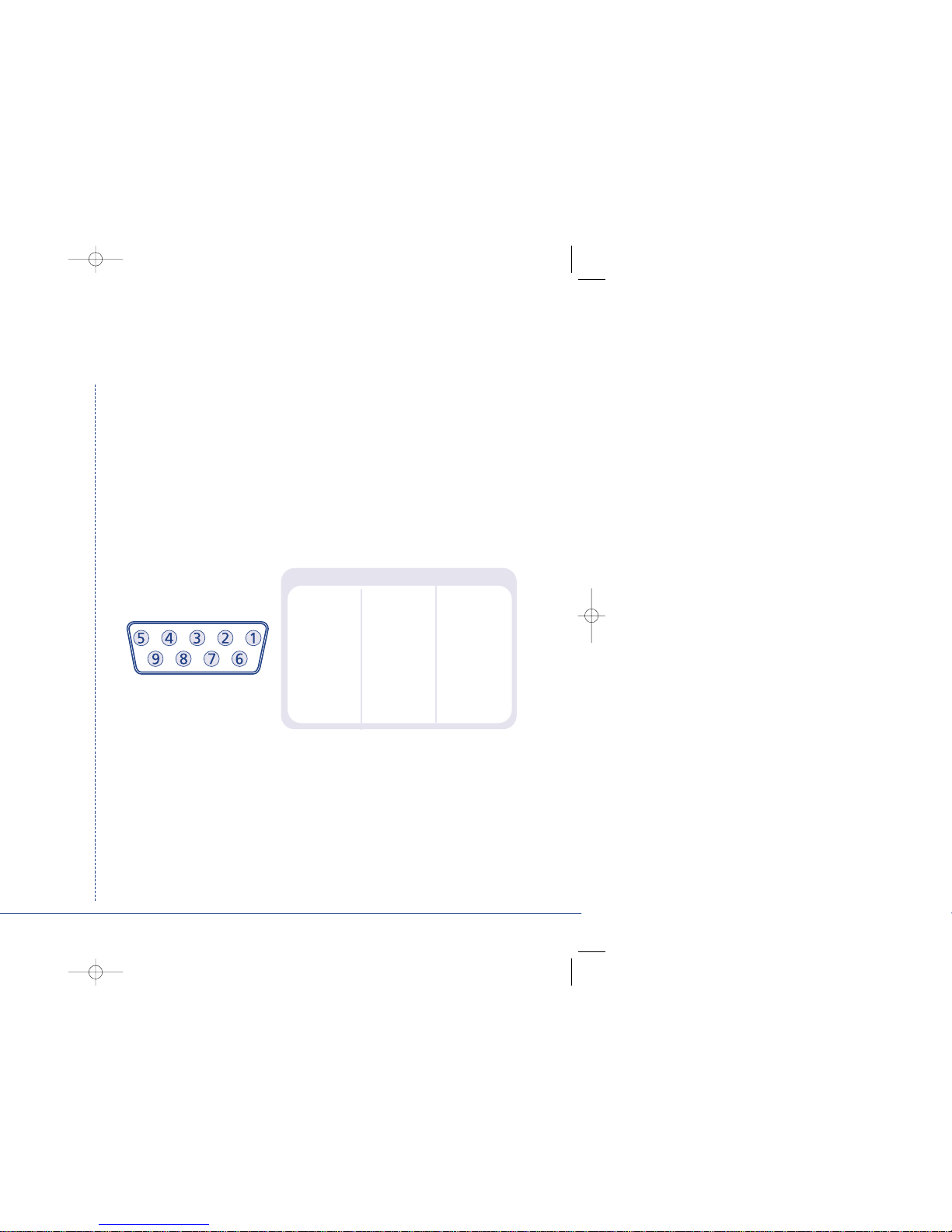
Serial port connection
The serial port on Digital Sprite Lite is a 9-way male D-type connection. A 9-way
D-type female plug is required with the following pin-outs:
PIN RS-232 RS-485
1 nc Data A
2RX nc
3TX nc
4 GND GND
5 GND GND
6nc nc
7RTS nc
8 CTS nc
9 nc Data B
nc = no connection
Note: The serial port must be configured for JVC or Ultrak telemetry in the
System Options menu.
c-bus/DTMF telemetry
Dedicated Micros telemetry receivers can be controlled using c-bus or DTMF
(telephone tones). When using c-bus telemetry the receiver is connected directly to
the c-bus connectors on the back of the unit. When using DTMF telemetry a
telemetry adaptor (TAD3) is required to convert the telemetry commands into DTMF
tones. DTMF and c-bus telemetry can be configured in a star or delta configuration.
Page 9

ENGLISH
7
®
or Jaz
®
Zip®and Jaz®disks are available in different disk capacities, the table below shows
the recording times at typical recording rates (at S-VHS image quality, 18KB):
1PPS 2PPS 3PPS 6PPS 12PPS 25PPS
Iomega Zip®100MB 1h 30m 45m 30m 15m 7m 3m
Iomega Zip
®
250MB 3h 46m 1hr 53m 1h 15m 37m 18m 9m
Iomega Jaz
®
1GB 15h 4m 7h 32m 5h 1m 2h 30m 1h 15m 36m
Iomega Jaz
®
2GB 30h 8m 15h 4m 10h 2m 5h 1m 2h 30m 1h 12m
Times indicate all cameras being copied to the disk.
3. DDS and VXA tapes
Images recorded to the internal disk can be automatically archived to Hewlett
Packard DDS and Ecrix VXA tapes. This allows a tape a day solution, similar to
that of a multiplexer and VCR. The disk size does not have to be large when
using tapes to archive images, although the disk size determines what is instantly
accessible from the Digital Sprite Lite.
The table below shows the number of hours a tape will last for when used at
different record rates (at S-VHS images quality, 18KB)
6hr 12hr 24hr 48hr 72hr 168hr
HP DDS-3 12GB 25PPS 14PPS 7PPS 3PPS 2PPS 1PPS
HP DDS-4 20GB 25PPS 23PPS 11PPS 5PPS 3PPS 1PPS
Ecrix VXA 20GB 25PPS 23PPS 11PPS 5PPS 3PPS 1PPS
See Appendix 1 for details of configuring Digital Sprite Lite for tape archiving.
Page 10

Connecting to a network
Digital Sprite Lite can be used to distribute high quality live or recorded images
across standard TCP/IP networks to a viewer’s desktop PC – where images can be
viewed using a standard web browser.
Digital Sprite Lite is available with or without network video capabilities. Units
with video network capabilities can be identified by the word ‘NET’ appearing
after the software version in the menu.
Note: Units without network video capabilities can still connect to a network but
only for upgrade purposes. Contact your local office for details of upgrading
Digital Sprite Lite for video networking.
To view images across a network you will need:
• A valid IP address, Default gateway, and Subnet mask for the Digital Sprite
Lite. These are usually obtained from your network administrator.
• A PC connected to the network with a minimum specification of:
200 MHz CPU.
64MB RAM.
4MB Video card (capable of displaying 16 million colours).
Microsoft
®
Windows®95, 98, or NT, or MacOS 7.5.
• A spare 10-baseT Ethernet port on the network.
• An RJ-45 network cable for connection between the Digital Sprite Lite and
the network.
• Microsoft Internet Explorer 5.X (PC) or Netscape Navigator 4.X (PC and Mac).
Page 11

ENGLISH
9
Connecting c-bus devices
Digital Sprite Lite uses the c-bus networking system to allow multiple Digital Sprite
Lites, remote keyboards, alarm modules, video switchers, and other accessories to
be connected together. The total length of the c-bus network can be up to 1500m.
Connecting alarms
An optional alarm module is required if alarms are to be added to Digital Sprite
Lite. The advantage of using alarm modules is that all the alarm connectors do
not have to be routed back to the Digital Sprite Lite. Multiple alarm modules can
be used on the c-bus network with alarms connected to each module.
To add alarms:
• Connect the corresponding alarm contact to the alarm input, i.e. Alarm 2
would be connected between ground (GND) and A2.
• If multiple alarm modules are required then each will need to be addressed;
consult the alarm module documentation for details.
• Connect the c-bus cable from the alarm box to one of the c-bus sockets on
Digital Sprite Lite.
• The polarity of the alarms (normally open/closed) is set using the ‘Alarms and
Presets’ menu page.
An alarm trigger performs the following
Action Menu page
Close/Open relay 1 Alarm Setup
Automatically copy the alarm camera to Zip® or Jaz® Alarm Setup
Display the alarm camera on screen Alarm Setup
Change the record rate Record Schedule
Record exclusively or interleave the alarm cameras Record Schedule
GND
A1 A2 A3 A4
Page 12

The example below shows a remote keyboard connected to the Digital Sprite Lite:
Video switchers
Video switchers allow multiple Digital Sprite Lites to be controlled from a single or
pair of monitors. This allows the flexibility of controlling up to 256 cameras from
a single location without having to purchase extra matrix equipment. The video
switcher routes the monitors from the Digital Sprite Lite being controlled to the
operator’s monitors, up to 16 control positions can have monitor switching.
The example below shows two Digital Sprite Lites controlled from individual
control points. The video switcher routes the monitor outputs from the Digital
Sprite Lites to the control points:
TIP: Each c-bus device is supplied with a 2m c-bus cable. To extend the distance
between devices, two c-bus junction boxes and power supply are required. A total
distance for the whole c-bus network can be up to 1500m.
Remote Keyboard
Main & Spot Monitors
c-bus
main & spot monitorsmain & spot monitors
Remote Keyboard Remote Keyboard
c-bus
c-bus
Video Switcher
c-bus
Page 13

ENGLISH
11
Example of using the menu to change the time:
1. Press and hold the mode or menu key to display the menu page above.
2. Use the cursors to select the Time option on the left hand side
of the menu.
3. Use the cursor to highlight the minute settings.
Time, Date & Language
Date 30/10/2000
Time W 12:00
Date format Day, Month
Language English
Time, Date & Language
Date 30/10/2000
Time W 12:00
Date format Day, Month
Language English
Time, Date & Language
Date 30/10/2000
Time W 12:00
Date format Day, Month
Language English
Date
Time
00
Page 14

Time, Date & Language
Date
As default, the date is entered DD:MM:YYYY on PAL models and MM:DD:YYYY
on NTSC models, this can be changed using the Date format option below.
Time
The time should be entered in 24 hour format (HH:MM).
Note: Summer and Winter time is signalled by an ‘S’ or ‘W’ next to the time.
Date format
The date format can be changed from Day, Month to Month, Day depending on
regional preference.
Language
The menus can be displayed in a number of languages. Upon selection these are
presented as a dropdown list.
Note: When the time and date is displayed as ‘External clock’ the time and date
settings are being taken from unit 1 on the c-bus network.
WARNING: Images may be overwritten if the time or date is adjusted whilst
recording is in progress.
Time, Date & Language Date 01/10/2000
Time S 12:00
Date Format Day, Month Month, Day
Language English Français, Deutsch, Espanól, Italiano
Page 15

ENGLISH
13
Schedule
A schedule can be used to record selected cameras at different times, change the
record rates, and select whether alarms or activity is enabled.
The schedules have three options:
• Off – the schedule is disabled
• Set/Unset – use a switch or alarm input to trigger the schedule. This is
connected directly to the AUX input, or by using a specific contact on an
external alarm module.
• On between – the schedule is triggered between user defined times (and days
for the weekend schedule).
The schedule gives the option to switch to night and weekend settings, either
manually using the Set/Unset option, using either the AUX input or alarm
contacts, or automatically at pre-set times and days.
Note: The Weekend setting overrides any night settings during the defined
weekend period.
Night Off
Set/Unset Direct
Module 01 contact 01
On between 18:00 and 09:00
Weekend Off
Set/Unset Direct
Module 01 contact 01
On between Friday 18:00
Monday 09:00
Page 16

Record Schedule
The record rate determines the amount of time and the update rate of images
recorded to disk. Settings can be applied to day, night and weekend schedules
using the following menu:
Standard/Event PPS
Choose the record rate in pictures per second (PPS) to be recorded across all
cameras. The maximum record rate is 25PPS for PAL and 30PPS for NTSC with a
single camera recorded. When multiple cameras are connected the maximum
record rate is 17PPS.
Standard PPS Event PPS Events active Event mode
Day 7 7 Both Interleave
Alarms Exclusive
Activity Unchanged
None
Night 7 7 None Interleave
Alarms Exclusive
Activity Unchanged
Both
Weekend 3 3 None Interleave
Alarms Exclusive
Activity Unchanged
Both
Recorded file size 18 KB
Max recording time --:-Total video storage 30GB
Earliest recording 01/10/2000 12:00
Note: The Night and Weekend options are only displayed if a corresponding
Night and Weekend schedule has been configured in the Schedule menu.
Page 17

ENGLISH
15
Maximum recording time
The maximum recording time is the amount of time recorded before images are
overwritten. It is calculated automatically when the record rate (PPS) is selected
or changed.
Tip: The maximum recording time can be increased by lowering the file size or
record rate.
Total video storage
The figure displayed shows the total amount of internal and external (RAID) disk
capacity available for video storage.
Earliest recording
The date and time of the first image on the disk are displayed.
See Appendix 2 for information on selecting record rates for different hard disk sizes.
For further information on record rates, and to download an interactive record
rate calculator visit the Dedicated Micros web site at:
www.dedicatedmicros.com
Recording events only
Digital Sprite Lite can be configured to record cameras with activity or alarm
events only, which can increase the amount of time the hard disk can record for
before being overwritten.
To configure Digital Sprite Lite for event only recording:
1. Set the Standard PPS to 00.
2. Set the Event PPS to the desired record rate when an event is detected.
3. Select the ‘Events active’ option as either Both, Alarms, or Activity as required.
4. Select ‘Event mode’ option as Exclusive to record only cameras with alarms or activity.
Only activity or alarm events will now be recorded. Note that pre-alarm/activity is
not possible in this configuration.
Page 18

Activity Setup
Pre-activity
Pre-activity images can be recorded for a pre-set time prior to an activity event.
Select the number of minutes or seconds (30 min 59 sec maximum).
Note: Pre-Activity Recording only occurs if standard recording is taking place.
Post-activity
Post-activity images can be recorded for a pre-set time after an activity event.
Select the number of minutes or seconds (30 min 59 sec maximum).
Auto copy
Activity events can be automatically copied to an external Zip®or Jaz® disk.
Activity relay (R2)
Choose whether the activity relay (R2) will open or close when activity
is detected. R2 will clear when activity is no longer detected.
Activity display
By default, the last camera with activity detection is not displayed on the main
monitor. Select ‘Yes’ to display cameras with activity.
Activity SetUp Pre-activity 00 min 00 sec
Post-activity 00 min 00 sec
Auto copy No Yes
Activity relay (R2) Close Open
Activity display No Ye s
Page 19

ENGLISH
17
Passwords
This menu is used to configure password protection.
User password
When a user password is entered all menus except Time, Date & Language
and Schedule are disabled. To set the password, select On and follow
on-screen instructions.
Installer password
A password can be set to prevent unauthorised users from accessing any installer
menus. To set the password, select On and follow on-screen instructions.
Playback protection
When playback protection is on, an installer or user password must be entered
to play back images. No password is required if playback protection is off.
Warning: For security reasons, loss of passwords will require the unit to be
returned for the passwords to be reset.
Passwords User password Off On
Installer password Off On
Playback protection Off On
Page 20

Factory default
Use this option to return all settings to the factory condition.
Recording
By default, recording is always enabled. If you do not want to record,
select Disabled.
System shutdown
Before removing power from the unit, select this option and follow
on-screen instructions.
Warning: Data loss may occur if a system shutdown is not performed before
removing power.
Event copy destination
Each external backup device connected to the unit is automatically detected on
power up. Select the correct external backup device for copying events. Events
can only be copied to removable media such as Iomega Zip®or Jaz®.
Serial telemetry type
Select the telemetry type connected to the serial port; JVC, Ultrak or none.
Page 21

ENGLISH
19
Alarms and Presets
Camera XX
The currently selected camera number is displayed, along with its status – detected
or not detected. Use the camera keys to select a camera to configure alarms
and presets.
Telemetry protocol
Select the telemetry protocol for the camera; BBV, Pelco, DM, JVC*, Ultrak*, or none.
*JVC or Ultrak will only appear if they are selected in the ‘System options’ menu.
Preset
If the camera has telemetry presets configured, these can be recalled when an
alarm is triggered. Enter the preset number from 00 to 99 for the corresponding
alarm contact. Up to 8 presets can be set for each camera with different alarm
contacts.
Module
Up to 16 alarm modules can be connected to the c-bus network. Each alarm
module is addressed from 01 to 16 - select the address of the alarm module
being used. Details of setting the address can be found in the manual included
with the alarm module.
Contact
Each alarm module has 16 alarm inputs, each input can be used by any camera
or multiple cameras.
Input
Select whether the alarm contact is normally open (N/O) or normally closed (N/C).
Alarms and Presets Camera XX Detected Not Detected
Telemetry protocol None BBV, Pelco, DM, JVC, Ultrak
Preset Module Contact Input
> -- 01 01 N/O
>----
Page 22

Activity test
Use this option to test and tune the sensitivity and activity grid set up for each
camera. When activity is detected on the camera a white dot is displayed. Press
the mode or menu key to exit the test.
Activity detection can perform the following:
Action Menu page
Close/Open relay 2 Activity Setup
Automatically copy the activity to Zip® or Jaz® Activity Setup
Display the activity camera on screen Activity Setup
Change the record rate Record Schedule
Record exclusively or interleave the activity cameras Record Schedule
Page 23

DIGITAL
Viewing single cameras
Full
Pressing a camera key will display a full screen image of that camera.
Note: On 16-way units, press shift to toggle between cameras 1-8 and 9-16.
Zooming an image
Press the same camera key to toggle zoom on and off.
When zoom is enabled, use to scroll around the image.
Freezing an image
Double press the camera key or press the Hold key on the remote keyboard to toggle freeze
frame on or off.
Viewing multiple cameras
Picture in Picture
Press the PIP key to toggle the main and PIP image.
Press and hold the PIP key to edit the display, use to select the segment,
press the required camera key to fill that segment.
Press mode/menu to exit.
Quad
Press the QUAD key to switch to quad display.
Press and hold the QUAD key to edit the display, use to select the segment,
press the required camera key to fill that segment.
Press mode/menu to exit.
Multi-screen
Press the multi-screen key to toggle between 9-way, 8+2, 12+1*, and 16-way* displays.
Press and hold the Multiscreen key to edit the display, use to select the segment,
press the required camera key to fill that segment.
Press mode/menu to exit.
*16 channel version only.
Sequencing cameras
Sequence
Press the sequence key to toggle the main monitor sequence on or off.
Press and hold the sequence key to edit the sequence.
Use the camera keys to include or remove cameras from the sequence.
Press mode/menu to exit.
Note: The spot monitor sequence can only be activated or edited in spot mode.
Viewing cameras on the Spot monitor
Press the mode key or spot key on the remote keyboard to toggle ‘spot’ mode, indicated on the main
monitor and the front panel LED.
Press a camera key to display that camera on the spot monitor.
1
V
9 way model shown
Page 24

Remote keyboard features
Controlling Telemetry cameras
Pan and Tilt
The joystick is used to control pan and tilt telemetry function. It provides proportional control of variable
speed telemetry.
Lens control
There are four lens functions on the keyboard: Zoom in/out, and Focus near/far.
Auxiliary functions
The following auxiliary functions are available:
- Press and hold to activate the wash function (if available)
- Toggle wiper on and off (if available)
- Toggle lamps on and off (if available)
- Toggle the auto-pan function on or off (not supported with Pelco domes)
- Toggle the patrol mode on or off (not supported with Pelco domes)
Star commands
The *command key is used to send commands directly to the telemetry receiver, refer to the receiver manual
for valid commands.
Storing a preset
1. Press and hold the preset key – A pop-up box appears.
2. Enter the two digit preset number using the camera keys. Camera 10 denotes number 0, for example,
preset 7 should be entered as camera 10 and camera 7.
3. The pre-set is stored when the pop-up box disappears.
Recalling a preset
1. Press the preset key – A pop-up box appears.
2. Enter the two digit preset number using the camera keys. Camera 10 denotes number 0, for example,
preset 7 should be entered as 10 and 7.
3. The pop-up box disappears and the camera will move to the preset position.
Controlling multiple Digital Sprite Lites
To select a unit to control:
1. Press the Unit Select key on the keyboard.
2. Press the camera key which corresponds to the unit number you wish to control. For example, press
camera 3 to select unit 3.
3. The keyboard is now logged onto the selected unit.
auto-pan
patrol
Page 25

ENGLISH
21
3. Configure an Eject Schedule (optional)
If no Eject Schedule is configured, then by default, Digital Sprite Lite will eject
each tape when it is full. An Eject Schedule will eject the tape at a specific time of
the day whether it is full or not. This is useful if the tape needs to be changed at a
set time each day, or if more than one tape is to be used in a day.
To configure an Eject Schedule:
1. Move the cursor to Eject Schedule using the keys.
2. Press the cursor key to display the eject schedule in a new window.
3. Use the keys to move to the required day, and the keys to highlight
the required field.
4. Use the keys to change the eject time in each field, up to 4 eject times
can be set for each day.
5. Press mode/menu to exit the Eject Schedule page.
Page 26

#" keys to
WARNING: Do not use the eject button on the front of the tape drive to eject
tapes, as this will cause data to be lost.
Archiving to tape
The difference between archiving on a VCR and archiving on a tape drive is that
the VCR is archiving images constantly, whereas the tape is archiving images
periodically from the internal disk.
The advantages of archiving periodically is that unlike videotape, a tape can be full
(or even ejected) and images will still be recorded to the internal disk, therefore
images are still recorded when changing tapes. There is also less mechanical wear
on the tape drive, as it is not recording all the time.
To archive images to tape:
1. Insert a tape into the tape drive.
2. The tape status box is displayed, showing the contents of the tape, along with
the following menu:
Note: It is normal for a few minutes to elapse before the above menu is displayed
as the tape needs to rewind and read the index.
> Background archive
> Selective archive
> Playback
> Load files
> Eject Tape
>
Page 27

ENGLISH
23
Installation:
1. Insert the disk into drive A.
2. Select Start > Run…
3. Type ‘a:\setup’ and click OK, alternatively use the Browse button to find the
file manually.
4. Installation will start, follow the on screen instructions.
Running the PC Playback software:
1. Select Start > Programs > PC Playback.
2. Click on the PC Playback icon.
3. PC Playback will load, click on the ‘Help’ option for operating instructions.
Important notes when using tape drives:
The cable supplied with the DDS drive may not be compatible with Digital Sprite
Lites 50-pin SCSI port.
DDS-3: A High-density 50-way male to Centronics 50-way male cable.
DDS-4: A High-density 50-way male to High-density 68-way male (DDS-4) is
required. This cable is available from computer suppliers.
Caution: Tape drives need frequent head cleaning to maintain optimum
performance, ensure the drive is cleaned to the manufacturer’s recommendations.
Page 28

Page 29

ENGLISH
25
Additional functions for the Ultrak dome
Functions which cannot be accessed directly from the remote keyboard can be
accessed using the ‘Preset’ command.
Recalling a preset
1. Press the ‘Preset’ key – a pop-up box appears.
2. Enter the two digit preset number using the camera keys. Camera 10 denotes
number 0. For example, preset 80 should be entered as camera 8 and 10.
3. The pop-up box disappears and the camera will move to the preset position.
Preset number Function
80 Run tour 1
81 Run tour 2
82 Run tour 3
83 Program tour 1
84 Program tour 2
85 Program tour 3
86 Terminate tour programming
87 Run patrol 1
88 Run patrol 2
89 Run patrol 3
90 Start menu (same as *command key)
92 Toggle auto exposure
93 Toggle backlight compensation
95 Decrease goto preset speed
96 Increase goto preset speed
Page 30

 Loading...