

Page 1
www.dedicatedmicros.com
INSTALLATION MANUAL
MANUEL D’INSTALLATION
MANUALE D'INSTALLAZIONE
INSTALLATIONSHANDBUCH
MANUAL DE INSTALACIÓN
2025
Page 2
CE NOTICE (EUROPEAN UNION).
Marking by the symbol CE indicates compliance of this DM product (Dennard 2025 CCTV IR Lamp)
to the Electromagnetic Compatibility Directive 89/336/EEC, and the Low Voltage Directive
73/23/EEC of the European Union. Such marking is indicative that this system meets the following
technical standards.
• EN 61000-6-3 EMC Standard Residential, Commercial and Light Industry.
• EN 61000-3-3 Limitations of voltage changes, fluctuations and flicker in public low-voltage
supply systems for equipment with rated current up to 16A.
• EN 61000-3-2 Limits for harmonic current emissions for equipment with rated current up to 16A.
• EN 50130-4 Immunity requirements for components of fire, intruder and social alarm systems.
• EN 60950 Safety of IT and related equipment.
• EN 55022 Class B. Radiated Emissions Standard, suitable for Commercial or Residential use.
• EN 60825-1 Safety standard for LED’s and Lasers.
Further details about these applicable standards can be obtained from Dedicated Micros LTD. 11
Oak Street, Swinton, Manchester, M27 4FL.
A “Declaration of Conformity” with all relevant European Union Directives has been made, is on file
and is available from the Dedicated Micros address immediately above.
CE Mark
This product is marked with the CE symbol and indicates compliance with all
applicable directives.
Directive 89/336/EEC.
A “Declaration of Conformity” is held at Dedicated Micros Ltd.,
11 Oak Street, Swinton, Manchester M27 4FL.
Page 3

Dennard 2025 Installation Manual Page. 1
1. Introduction
Congratulations on choosing the Dennard 2025 infra-red LED illuminator. The product range is
designed for high power and long life illumination for cameras with spectral responses extending
into the infra-red range. With correct use the product will provide over 5 years of maintenance free
operation.
The unit comes with a dedicated power supply which requires a mains input. It must only be used
with this supply.
The illuminator and PSU are rated to IP66.
This operation manual will provide all the information required to set-up, install and run the
Dennard 2025 Illuminator.
Page 4

Dennard 2025 Installation Manual Page. 2
2. Index
Introduction 1
Index 2
Dennard 2025 Outline Drawing 3
Components Supplied 4
General Safety Information 5
Mounting the Illuminator 5
Mounting to a Dennard 2000 Pan and Tilt Unit 6
Mounting to a wall 6
Mounting the Control Unit 6
Wiring connections 9
Configuration 11
Power Settings 12
Control Settings 12
Using the Photocell 12
Remote Switch Inputs 12
Adjusting the Illuminator Angle 14
Maintenance 15
Spares Parts and Accessories 16
Troubleshooting 16
Specifications 17
Page 5

Dennard 2025 Installation Manual Page. 3
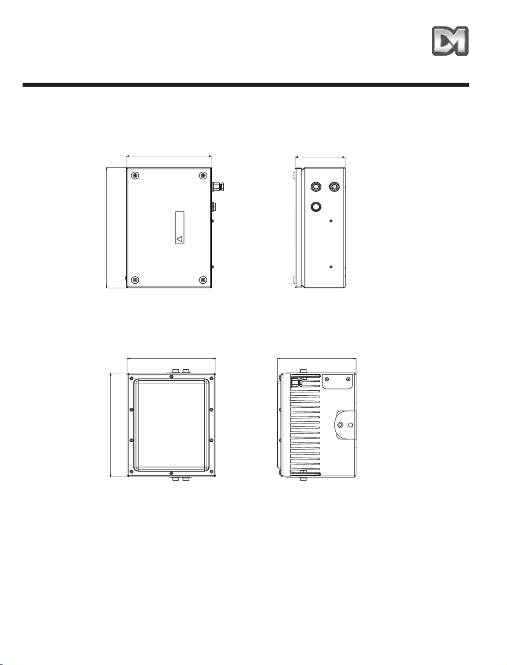
3. Dennard 2025 Outline Drawing
Fig. 1 – Outline Dimensions
117mm
200mm
184mm
208mm
258mm
300mm
PSU
LED illuminator
Page 6

Dennard 2025 Installation Manual Page. 4
4. Components Supplied
Before installation please remove the unit from the packaging and check that all items below have
been supplied.
1 x Dennard 2025 Infra-red LED illuminator
1 x Dennard 2025 Dedicated Power supply
1 x Dennard 2025 Wall bracket
1 x Accessory kit containing
1 x 6mm A/F Hex Wrench
1 x M8 x 20 Socket Cap Head Bolt
1 x M10 x 140 Hex Head Bolt
1 x M10 Nut
2 x M10 Lock Washers
2 x M10 x 16 Hex Head Bolts
2 x M10 Plain Washers
2 x M10 Spring Washers
1 x M8 Plain Washer
1 x M8 Spring Washer
4 x 8mm Woodscrews
4 x Rawlplugs
4 x M8 Rubber Dowty Washers
6 x Cable Ties
Page 7

Dennard 2025 Installation Manual Page. 5
5. General Safety Information
This Dennard 2025 equipment shall only be installed by qualified service personnel.
The final installation must adhere to all national wiring regulations.
The disconnect device must comply with IEC 60947.
WARNINGS
Read instructions before installing and power up.
Instructions should be kept for future reference.
If this unit shows signs of damage or malfunction, disconnect from mains immediately and contact
Dedicated Micros.
6. Mounting the Illuminator
Ensure the illuminator is mounted in a well ventilated area with over 100mm clearance around the
heatsink on all sides.
Avoid mounting the illuminator in direct sunlight or next to other heat sources.
Failure to provide this will shorten the life of the LEDs and decrease the lamp brightness.
WARNING: Ensure the illuminator is mounted a minimum of 2m away from eye level. Do not
look directly at the illuminator for prolonged periods during use.
Page 8

7. Mounting to a Dennard 2000 Pan and
Tilt Unit
Figures 2 and 3 show typical positions for I.R. illuminators when mounted to a remotely controlled
Dennard 2000 pan and tilt head.
Mount the Dennard 2025 illuminator using the M10 fixings supplied with the unit.
Due to the weight of the Dennard 2025 it is not recommended that it is used with the optional side
mounting plate on the pan and tilt unit.
8. Mounting to a wall
The illuminator can be mounted directly to a wall to allow up and down adjustment only.
Alternatively it can be mounted using the wall mounting bracket provided which also allows left to
right adjustment. See Fig. 4.
WARNING: Ensure the wall fixings used are suitable for the type of wall and can support the
full weight of the unit.
9. Mounting the Control Unit
Remove the sealing plugs as shown in Fig. 5 and then use the rawlplugs, screws and rubber
washers provided to mount the control unit to the wall. Use silicon sealant between the wall and
unit to ensure a water tight seal is maintained.
Dennard 2025 Installation Manual Page. 6
Page 9

Fig. 2 – Two illuminator configuration with Dennard 2000 Pan and Tilt Unit
Fig. 3 – Fixing Detail
Fig. 4 – Mounting the Illuminator to a wall using the wall bracket
Dennard 2025 Installation Manual Page. 7
Page 10

Fig. 5 – Removing the sealing plugs
Fig. 6 – Fitting the fixing screws and washers
Dennard 2025 Installation Manual Page. 8
Page 11

Dennard 2025 Installation Manual Page. 9
10. Wiring connections
Electrical connections to the Dennard 2025 illuminator are made via terminal blocks inside the
power supply unit. To access the connections remove the 4 cover screws on the power supply and
remove the top cover.
WARNING: Ensure the mains supply is isolated at all times whilst the cover is removed from
the power supply.
The mains supply should be fitted with a circuit breaker as a method of disconnecting the supply for
maintenance. The circuit breaker shall be accessible and labelled such that it is easily identified as
the disconnect device for this particular unit. The device shall comply with IEC 60947. The
disconnect device and all wiring shall be of adequate rating to comply with the input requirements
of the PSU as stated in the specifications section.
The mains cabling shall comply with national wiring regulations.
Ensure the mains input cable is prepared as in Fig. 8. Feed the cable through the lower cable gland
and secure the gland nut using a torque of 1.8Nm. Use the cable tie to secure the cable to the
mounting post provided as shown in Fig. 7.
Connect the cable from the illuminator into the connector and earth point as shown in Fig. 7. Use
the cable ties provided to attach the cable to the photocell wires which are routed around the right
hand side of the enclosure. Ensure the correct polarity is observed. The red sheathed wire
connects to the positive terminal, labelled as ‘LED ARRAY +ve’ on the PCB.
WARNING: Do not increase the cable length, as this may cause performance problems with
the unit. You may shorten the cable to a minimum length of 1m.
Page 12

The unit is supplied with a photocell connected and configured to switch the lamp on when light
levels fall below 25 lux. If you want the lamp to run continuously or to use an alternative switching
source please refer to the section ‘Remote Switch Inputs’.
Fig. 7 – Customer wiring
Dennard 2025 Installation Manual Page. 10
Feed mains cable through lower gland
and fasten to post with cable tie provided
Connect mains into terminal block green/yellow
to earth, brown to live (‘L’) blue to Neutral (‘N’)
Feed illuminator cable through upper
gland and secure to photocell wiring
using cable ties provided
Connect illuminator cable to terminal block,
observe correct polarity
Page 13

Fig. 8 - Mains Cable Preparation
11. Configuration
Power Settings
It is possible to configure the supply at 4 different power levels. The factory setting is high power.
If using the lamp at temperatures above 40°C or using continuously it is recommended that you use
Medium power or lower to maximise the life of the LEDs.
Switch 1 and 10 in the switch bank control the power level settings. The factory default setting is
high power.
Dennard 2025 Installation Manual Page. 11
CONNECTION TO DENNARD 2025 PSU
6mm STRIP AND
PREP FOR
TERMINAL
BLOCK
GREEN/YELLOW
EARTH
BLUE - NEUTRAL
BROWN LIVE
4-6mm OUTER
INSULATION DIAMETER
24mm MIN
20mm MAX OUTER
INSULATION REMOVED
CONNECTION TO CUSTOMER WIRING
BROWN - LIVE
GREEN/YELLOW
EARTH
BLUE - NEUTRAL
Switch 1 Switch 10 Power mode
ON ON Ultra low
ON OFF Low
OFF ON Medium
OFF OFF High
Page 14

12. Control Settings
The Denanrd 2025 illuminator can be switched from any one of three 12V switch inputs. The unit
comes configured to use the photocell supplied which switches the lamp on at light levels below 25
lux.
Using the Photocell
The unit is supplied and configured to use a photocell located inside the power supply unit. The
photocell relies on detecting ambient light to function correctly. Ensure that the control unit is
mounted with the cell pointing to one side or below the unit (not facing upwards). It needs to be
away from sources of artificial light and not blanked off or sitting in permanently dark conditions.
An extension kit is available for mounting the photocell remotely if required see ‘Spares and
Accessories’.
Remote Switch Inputs
There are a further two switch inputs designed for 5-12V devices. These can be configured to
accept a range of different signals, for example a closed contact input from a PIR detector or an
external control unit.
The inputs are configured as per the following table.
Dennard 2025 Installation Manual Page. 12
Page 15

E.g. To add another control input to the unit, wire it into the terminal block marked with CTRL I/P 2
then set switch bank switches 6 and 7 on. When the contacts on the input switch are closed the
light will come on, if you want the light to come on when the input contacts are open then set bank
switch 7 to off.
If multiple switches are connected the light will switch on when any of the switches are on (OR
control).
Dennard 2025 Installation Manual Page. 13
No.. Description ON= OFF= Factory Setting
1
POWER CONTROL 1
SEE POWER SETTINGS TABLE OFF
2 UNUSED OFF
3 ENABLE CONTROL
INPUTS
ALWAYS IN ON
POSITION
- ON
4 CTRL I/P 1 ENABLE
(PHOTOCELL)
INPUT ENABLED INPUT DISABLED ON
5 CTRL I/P 1 TYPE
(PHOTOCELL)
CLOSED SWITCH
INPUT = ARRAY ON
OPEN SWITCH
INPUT= ARRAY ON
ON
6 CTRL I/P 2 ENABLE INPUT ENABLED INPUT DISABLED OFF
7 CTRL I/P 2 TYPE CLOSED SWITCH
INPUT = ARRAY ON
OPEN SWITCH
INPUT= ARRAY ON
OFF
8 CTRL I/P 3 TYPE INPUT ENABLED INPUT DISABLED OFF
9 CTRL I/P 3 TYPE CLOSED SWITCH
INPUT = ARRAY ON
OPEN SWITCH
INPUT= ARRAY ON
OFF
10 POWER CONTROL 2 SEE POWER SETTINGS TABLE OFF
Page 16

13. Adjusting the Illuminator Angle
Once you have completed the connections and have powered on the illuminator you will need to
set the angle to get the best possible performance.
• View the area you wish to illuminate through a camera and monitor.
• If you are using the wall bracket then loosen the bolt on the bracket and move the illuminator so
it is pointing towards the area you wish to see. Tighten the bolt.
• Loosen the bolts on the side of the illuminator and tilt the lamp downwards until the near part of
the view is clearly illuminated. (viewed via the monitor).
• Slowly tilt the lamp upwards until the far part of the field of view is also illuminated. Tighten the
bolts to set this position.
Fig. 10 – Adjusting the Illuminator Angle
Dennard 2025 Installation Manual Page. 14
IR Illumination
Nearest Object
Furthest Object
Page 17

Dennard 2025 Installation Manual Page. 15
14. Maintenance
The only serviceable part in the illuminator assembly is the front window. This shall only be serviced
by trained staff. No other parts of the unit are serviceable.
The only serviceable parts inside the PSU are the fuses.
Mains input fuse: This is identified as F1 on the label inside the PSU. This is a time lag (slow
blow) fuse with 2A current rating, 250V rating and high breaking capacity.
Illuminator output fuse: This is identified as F2. This is a time lag (slow blow) fuse with 10A
current rating, 250V rating and high breaking capacity.
To change a fuse, remove the black fuse holder from the terminal block by pulling upwards.
Remove the old fuse and replace with the new component. The new fuse must have the same
ratings as detailed above. Replace the fuse holder into the terminal block.
In case of a fault with the unit, consult the troubleshooting section in the manual.
Page 18
15. Spares Parts and Accessories
16. Troubleshooting
WARNINGS
Disconnect from mains before removing the cover
If this unit shows signs of damage or malfunction, disconnect from mains immediately and contact
Dedicated Micros.
• In dark conditions you will be able to see a faint red glow from the LEDs. In daylight you will not
see anything at all unless you look at the lamp with a camera.
• Check mains supply is connected correctly and switched on. Supply should be 100-240V ~.
• Check polarity of connections to lamp.
• Check the photocell function (put opaque tape over photocell) and wait for a few seconds to see
if the product switches on.
• Check the 2A and 10A fuses inside the PSU and replace if necessary.
• Disconnect all control devices and switch all switches in the switch bank to the off position, to
check if the lamp illuminates.
Dennard 2025 Installation Manual Page. 16
Part no. Description
Dennard 95083 Replacement power supply unit
Dennard 95084 Replacement illuminator unit 850nm/30 degree angle
Dennard 94032 Photocell extension kit – kit to allow photocell to be mounted remotely from
PSU
Dennard 95086 Replacement window
Dennard 95087 Replacement photocell
Page 19

Dennard 2025 Installation Manual Page. 17
17. Specifications
Voltage Input: 100-240V~ 50-60Hz
Power Input: 120W
Mains input Fuse: 2A, time lag, high breaking capacity.
Illuminator input fuse: 10A, time lag, high breaking capacity.
IP Rating: B.S. EN 60529, IP 66
Other Approvals: EN 61000-6-3 EMC Standard Residential, Commercial and Light Industry.
EN 61000-3-3 Limitations of voltage changes, fluctuations and flicker in public low-voltage supply
systems for equipment with rated current up to 16A.
EN 61000-3-2 Limits for harmonic current emissions for equipment with rated current up to 16A.
EN 50130-4 Immunity requirements for components of fire, intruder and social alarm systems.
EN 60950 Safety of IT and related equipment.
EN 55022 Class B. Radiated Emissions Standard, suitable for Commercial or Residential use.
EN 60825-1 Safety standard for LED’s and Lasers.
Operating temperature: -20°C to 50°C. Out of direct sunlight.
Weight: Illuminator unit and main bracket: 7 kg
Wall bracket: 1 kg
PSU: 5 kg
Page 20

Notes
Page 21

2025
MANUEL D’INSTALLATION
Page 22

Dennard 2025 Manuel d’installation Page 20
1. Introduction
Nous vous félicitons d’avoir choisi le projecteur à DEL infrarouge Dennard 2025. La gamme de
produits est conçue pour assurer une source d’éclairage haute puissance et de longue durée aux
caméras à réponse spectrale s’étendant dans la zone infrarouge. Utilisé correctement, ce
projecteur assurera un fonctionnement sans maintenance pendant 5 ans.
Le projecteur est fourni avec un bloc d’alimentation électrique dédié qui requiert une alimentation
secteur. Il ne doit être utilisé qu’avec cette alimentation.
Le projecteur et le bloc d’alimentation ont un niveau de protection contre les intempéries IP66.
Le manuel d’installation offre toutes les informations requises pour configurer, installer et utiliser le
projecteur Dennard 2025.
Page 23

Dennard 2025 Manuel d’installation Page 21
2. Index
Introduction 20
Index 21
Plan de forme Dennard 2025 22
Composants fournis 23
Informations générales de sécurité 24
Montage du projecteur 24
Montage sur une caméra panoramique et inclinaison Dennard 2000 25
Fixation murale 25
Montage de l’unité de commande 25
Raccordements de câbles 28
Configuration 30
Réglages de puissance 31
Réglages de commande 31
Utilisation de la cellule photoélectrique 31
Entrées de commutation à distance 31
Réglage de l’angle du projecteur 33
Maintenance 34
Pièces de rechange et accessoires 35
Dépannage 35
Caractéristiques 36
Page 24
Dennard 2025 Manuel d’installation Page 22
3. Plan de forme Dennard 2025
Fig. 1 – Dimensions extérieures
117mm
200mm
184mm
208mm
258mm
300mm
Bloc d'alimentation électrique
LED illuminator
Page 25

Dennard 2025 Manuel d’installation Page 23
4. Composants fournis
Avant de procéder à l’installation, veuillez sortir le projecteur de l’emballage et vérifier que tous les
éléments listés ci-dessous sont inclus.
1 projecteur à DEL infrarouge Dennard 2025
1 bloc d’alimentation dédié Dennard 2025
1 support mural Dennard 2025
1 kit d’accessoires contenant
1 clé hexagonale 6 mm
1 vis à tête creuse M8 x 20
1 vis à tête à six pans M10 x 140
1 écrou M10
2 rondelles frein M10
2 vis à tête à six pans M10 x 16
2 rondelles lisses M10
2 rondelles élastiques M10
1 rondelle lisse M8
1 rondelle élastique M8
4 vis à bois 8 mm
4 chevilles
4 rondelles caoutchouc
6 attache-câbles
Page 26

Dennard 2025 Manuel d’installation Page 24
5. Informations générales de sécurité
Ce projecteur Dennard 2025 ne doit être installé que par des techniciens qualifiés.
L’installation finale doit être conforme à la réglementation nationale en vigueur en matière de
câblage.
Le sectionneur doit être conforme à la norme IEC 60947.
MISE EN GARDE
Veuillez lire les instructions avant de procéder à l’installation et la mise sous tension.
Conservez les instructions pour référence ultérieure.
En cas de signes de dégâts ou de dysfonctionnement de ce matériel, isolez-le électriquement au
niveau du sectionneur de l’alimentation secteur et contactez Dedicated Micros.
6. Montage du projecteur
Veillez à ce que le projecteur soit monté dans un endroit bien ventilé et avec un espace de 100 mm
sur tous les côtés du dissipateur thermique.
Evitez de monter le projecteur en plein soleil ou à proximité d’autres sources de chaleur,
car ceci écourterait la durée de vie des diodes électroluminescentes et réduirait la luminosité du
projecteur.
MISE EN GARDE : Veillez à ce que le projecteur soit monté à 2 m au moins de la hauteur des
yeux. Ne regardez pas directement le projecteur pendant des périodes prolongées lorsqu’il
est allumé.
Page 27

7. Montage sur une caméra panoramique et
inclinaison Dennard 2000
Les Figures 2 et 3 illustrent les positions typiques des projecteurs infrarouge lorsqu’ils sont montés
sur une tête panoramique et inclinaison Dennard 2000 télécommandée.
Montez le projecteur Dennard 2025 à l’aide des fixations M10 fournies avec le projecteur.
En raison du poids du Dennard 2025, nous déconseillons son utilisation avec la plateforme de
montage latérale en option de la caméra panoramique et inclinaison.
8. Fixation murale
Le projecteur peut être monté directement sur un mur, auquel cas il n’est réglable qu’en hauteur. Il
peut aussi être monté à l’aide du support de fixation murale fourni, auquel cas il est également
réglable latéralement. Voir la Fig. 4.
MISE EN GARDE : Veillez à ce que les fixations murales utilisées soient compatibles avec le
type de mur et capables de supporter le poids total du projecteur.
9. Montage de l’unité de commande
Retirez les obturateurs comme illustré à la Fig. 5, puis utilisez les chevilles, vis et rondelles
caoutchouc fournies pour fixer l’unité de commande au mur. Utilisez du mastic silicone entre le mur
et le projecteur pour assurer le maintien de l’étanchéité.
Dennard 2025 Manuel d’installation Page 25
Page 28

Fig. 2 – Configuration à deux projecteurs avec caméra panoramique et inclinaison Dennard 2000
Fig. 3 – Détail de la fixation
Fig. 4 – Fixation au mur du projecteur à l’aide du support mural
Dennard 2025 Manuel d’installation Page 26
Page 29

Fig. 5 – Retrait des obturateurs
Fig. 6 – Pose des vis et rondelles de fixation
Dennard 2025 Manuel d’installation Page 27
Page 30

Dennard 2025 Manuel d’installation Page 28
10. Raccordements de câbles
Les raccordements électriques au projecteur Dennard 2025 s’effectuent au moyen de borniers
situés à l’intérieur du bloc d’alimentation. Pour accéder aux raccordements retirez les 4 vis du capot
du bloc s’alimentation et retirez le capot du dessus.
MISE EN GARDE : Veillez à ce que l’alimentation secteur soit isolée à tout moment lorsque
le capot est retiré du bloc d’alimentation.
L’alimentation secteur doit être dotée d’un disjoncteur à fonction de dispositif de coupure de
l’alimentation aux fins de maintenance. Le disjoncteur doit être accessible et étiqueté de manière à
pouvoir être facilement identifié comme étant le dispositif de coupure réservé à cet équipement. Le
dispositif doit être conforme à la norme IEC 60947. Le dispositif de coupure et tout le câblage
doivent être de l’intensité adéquate pour répondre aux besoins en alimentation du bloc
d’alimentation spécifiés dans la section Caractéristiques.
Le câblage de l’alimentation secteur doit être conforme à la réglementation nationale en vigueur en
matière de câblage.
Veillez à ce que le câble d’alimentation secteur soit préparé comme illustré à la Fig. 8. Passez le
câble dans le presse-étoupe inférieur et serrez l’écrou de la presse-étoupe au couple de 1,8 Nm.
Utilisez l’attache-câble fournie pour immobiliser le câble sur le support comme illustré à la Fig. 7.
Raccordez le câble du projecteur au connecteur et à la mise à la terre comme illustré à la Fig 7.
Utilisez les attache-câbles fournies pour attacher le câble aux fils de la cellule photoélectrique qui
sont acheminés à droite du caisson. Veillez à respecter la polarité. Le fil blindé rouge est raccordé
à la borne positive, étiquetée ‘LED ARRAY +ve’ sur la carte à circuits imprimés.
MISE EN GARDE : Ne rallongez pas le câble, ceci risquerait de compromettre la performance
de l’équipement. Vous pouvez raccourcir le câble d’une longueur minimum de 1 m.
Page 31

Le projecteur est fourni avec une cellule photoélectrique raccordée et configurée pour que le
projecteur s’allume lorsque le niveau d’éclairage baisse en dessous de 25 lux. Si vous voulez que
le projecteur fonctionne continuellement ou utiliser une autre source de commutation, veuillez vous
reporter à la section ‘Entrées de commutation à distance’.
Fig. 7 – Câblage à effectuer par le client
Dennard 2025 Manuel d’installation Page 29
Passez le câble d’alimentation secteur
dans le presse-étoupe du bas et fixez-le
sur le support avec l’attache-câble fournie
Raccordez l’alimentation secteur au bornier, fil
vert/jaune à la terre, fil marron au fil sous
tension (‘L’) bleu au fil Neutre (‘N’)
Passez le câble du projecteur dans le
presse-étoupe du haut et immobilisez
le câblage de la cellule photoélectrique
avec les attache-câbles fournies
Raccordez le câble du projecteur au bornier en
respectant la polarité
Page 32

Fig. 8 - Préparation du câble d’alimentation secteur
11. Configuration
Réglages de puissance
Il est possible de configurer l’alimentation à 4 différents niveaux de puissance. Le réglage usine est
le réglage haute puissance.
Si le projecteur fonctionne à des températures supérieures à 40°C ou continuellement, nous vous
conseillons d’utiliser une puissance moyenne ou basse pour maximiser la durée de vie des diodes.
Les commutateurs 1 et 10 de la rangée de commutateurs commandent les réglages de niveau de
puissance. Le réglage usine par défaut est le réglage haute puissance.
Dennard 2025 Manuel d’installation Page 30
RACCORDEMENT AU BLOC D’ALIMENTATION DU DENNARD 2025
6 mm DENUDER
ET PREP. POUR
BORNIER
TERRE
VERT/JAUNE
BLEU - NEUTRE
MARRON SOUS
TENSION
4-6mm DIAMETRE
ISOLATION EXTERIEURE
24 mm MIN
20 mm MAX ISOLATION
EXTERIEURE RETIREE
RACCORDEMENT AU CABLAGE DU CLIENT
MARRON SOUS TENSION
TERRE
VERT/JAUNE
BLEU - NEUTRE
Commutateur 1 Commutateur 10 Mode de puissance
ON ON Ultra Basse
ON OFF Basse
OFF ON Moyenne
OFF OFF Haute
Page 33

Dennard 2025 Manuel d’installation Page 31
12. Réglages de commande
Le projecteur Dennard 2025 peut être commuté à partir de l’une de trois entrées de commutation
12 V. Le projecteur est livré configuré pour utiliser la cellule photolélectrique fournie qui allume le
projecteur à des niveaux de luminosité en dessous de 25 lux.
Utilisation de la cellule photoélectrique
Le projecteur est fourni et configuré pour utiliser une cellule photoélectrique située à l’intérieur du
bloc d’alimentation. La cellule photoélectrique dépend de la détection de la luminosité ambiante
pour fonctionner correctement. Veillez à ce que l’unité de commande soit montée avec la cellule
dirigée vers un côté ou sous l’unité (et non pas dirigée vers le haut). Elle doit être éloignée des
sources d’éclairage artificiel et ne pas être masquée, ou ne pas résider dans des endroits sombres
en permanence.
Un kit de rallonge est disponible pour le montage à distance de la cellule photoélectrique si besoin
est. Voir ‘Pièces de rechange et accessoires’.
Entrées de commutation à distance
Deux autres entrées de commutation conçues pour des dispositifs de 5-12 V sont également
présentes. Elles peuvent être configurées pour accepter une gamme de différents signaux, à savoir
signaux d’entrée de contact fermé depuis un détecteur PIR ou d’une unité de commande externe.
Les entrées doivent être configurées conformément au tableau suivant.
Page 34

Exemple : pour ajouter une autre entrée de commande à l’unité, raccordez-la au bornier repéré
CTRL I/P 2 puis, activez les commutateurs 6 et 7 de la rangée de commutateurs (ON). Lorsque les
contacts du commutateur d’entrée sont fermés, le projecteur s’allume, si vous voulez qu’il s’allume
lorsque les contacts d’entrée sont ouverts, désactivez alors le commutateur 7 (OFF).
Si des commutateurs multiples sont raccordés, le projecteur s’allume lorsque l’un des
commutateurs quel qu’il soit est activé (ON) (OU commande).
Dennard 2025 Manuel d’installation Page 32
No. Désignation ON= OFF= Réglage usine
1
COMMANDE DE
PUISSANCE 1
VOIR LE TABLEAU DES REGLAGES DE
PUISSANCE
OFF
2
NON UTILISE
OFF
3
ACTIVATION ENTREES
COMMANDE
TOUJOURS SUR ‘ON’ -
ON
4
CTRL I/P 1 ACTIVATION
(CELLULE
PHOTOELECTRIQUE)
ENTREE ACTIVEE ENTREE DESACTIVEE
ON
5
CTRL I/P 1 TYPE
(CELLULE
PHOTOELECTRIQUE)
ENTREE COMMUTATION
FERMEE = MATRICE
ACTIVEE (ON)
ENTREE COMMUTATION
OUVERTE = MATRICE
ACTIVEE (ON)
ON
6
CTRL I/P 2 ACTIVATION ENTREE ACTIVEE ENTREE DESACTIVEE
OFF
7
CTRL I/P 2 TYPE ENTREE COMMUTATION
FERMEE = MATRICE
ACTIVEE (ON)
ENTREE COMMUTATION
OUVERTE = MATRICE
ACTIVEE (ON)
OFF
8
CTRL I/P 3 TYPE ENTREE ACTIVEE ENTREE DESACTIVEE
OFF
9
CTRL I/P 3 TYPE ENTREE COMMUTATION
FERMEE = MATRICE
ACTIVEE (ON)
ENTREE COMMUTATION
OUVERTE = MATRICE
ACTIVEE (ON)
OFF
10
COMMANDE DE
PUISSANCE 2
VOIR LE TABLEAU DES REGLAGES DE
PUISSANCE
OFF
Page 35

Dennard 2025 Manuel d’installation Page 33
13. Réglage de l’angle du projecteur
Une fois les raccordements effectués le projecteur mis sous tension, vous devrez régler l’angle
pour assurer les performances optimales.
• Visualisez l’endroit que vous souhaitez éclairer sur une caméra ou écran.
• Si vous utilisez le support mural, desserrez alors le boulon sur le support et déplacez le
projecteur de manière à le diriger vers la zone que vous souhaitez voir. Serrez le boulon.
• Desserrez les boulons sur le côté du projecteur et inclinez-le vers le bas jusqu’à ce que la partie
du champ de vision la plus proche soit clairement éclairé. (tel que vu à l’écran).
• Inclinez lentement le projecteur vers le haut jusqu’à ce que la partie du champ de vision la plus
éloignée soit également éclairée. Serrez les boulons pour régler cette position.
Fig. 10 – Réglage de l’angle du projecteur
Eclairage IR
Objet le plus proche
Objet le plus loin
Page 36

Dennard 2025 Manuel d’installation Page 34
14. Maintenance
La seule pièce remplaçable du projecteur est la vitre avant. Ne confiez cette intervention qu’au le
personnel ayant reçu la formation appropriée. Aucun autre composant du projecteur n’est
remplaçable.
Les seules pièces remplaçables à l’intérieur du bloc d’alimentation sont les fusibles.
Fusible d’entrée d’alimentation secteur : Ce fusible est identifié F1 sur l’étiquette à l’intérieur du
bloc d’alimentation. Ceci est un fusible à retardement de 2 A, 250 V et haute puissance de rupture.
Fusible de sortie du projecteur : Identifié sous F2. Ceci est un fusible à retardement de 10 A, 250
V et haute puissance de rupture.
Pour remplacer un fusible, retirez le porte-fusibles noir du bornier en tirant vers le haut. Retirez le
fusible à remplacer et remplacez-le par le fusible neuf. Le fusible neuf doit avoir les mêmes
puissances nominales que ci-dessus. Remettez le porte-fusibles dans le bornier.
En cas de panne du projecteur, reportez-vous à la section dépannage du manuel.
Page 37

Dennard 2025 Manuel d’installation Page 35
15. Pièces de rechange et accessoires
16. Dépannage
MISE EN GARDE
Débranchez de l’alimentation secteur avant de retirer le couvercle.
En cas de signes de dégâts ou de dysfonctionnement de ce matériel, isolez-le électriquement au
niveau du sectionneur de l’alimentation secteur et contactez Dedicated Micros.
• Dans un milieu sombre, vous constaterez une faible lueur rouge au niveau des diodes. En plein
jour, vous ne verrez rien sauf si vous regardez le projecteur avec la caméra.
• Vérifiez que l’alimentation secteur est correctement raccordée et sous tension. L’alimentation
doit être de 100-240V ~.
• Contrôlez la polarité des raccordements au projecteur.
• Contrôlez le fonctionnement de la cellule photoélectrique (cellule masquée par du ruban) et
attendez quelques secondes pour voir si le projecteur s’allume.
• Contrôlez les fusibles 2A et 10A à l’intérieur du bloc d’alimentation et remplacez-les le cas
échéant.
• Débranchez tous les dispositifs de contrôle et mettez tous les commutateurs de la banque de
commutateurs en position désactivée (OFF), pour voir si le projecteur s’allume.
Pièce no. Désignation
Dennard 95083 Bloc d’alimentation de rechange
Dennard 95084
Projecteur de rechange 850 nm/angle de 30°
Dennard 94032 Kit de rallonge de cellule photoélectrique – kit permettant de monter la cellule
photoélectrique à distance du bloc d’alimentation
Dennard 95086 Vitre de rechange
Dennard 95087 Cellule photoélectrique de rechange
Page 38

Dennard 2025 Manuel d’installation Page 36
17. Caractéristiques
Entrée de tension : 100 - 240 V~ 50 - 60 Hz
Entrée d’alimentation : 120 W
Fusible d’entrée d’alimentation secteur : 2 A, à retardement, haute puissance de rupture.
Fusible d’entrée de projecteur : 10 A, à retardement, haute puissance de rupture.
Indice IP : Norme B.S. EN 60529, IP 66
Autres homologations : EN 61000-6-3 Norme CEM Environnements résidentiels, commerciaux et
de l’industrie légère.
EN 61000-3-3 Limitations de changements de tension, fluctuations et vacillement de réseau de
distribution publique pour équipements d’une intensité de courant nominale de jusqu’à 16 A.
EN 61000-3-2 Limites des émissions de courant harmonique pour équipements d’une intensité de
courant nominale de jusqu’à 16A.
EN 50130-4 Prescriptions relatives à l’immunité des composants de systèmes de détection
d’incendie, d’intrusion et d’alarme sociale.
EN 60950 Sécurité des équipements informatiques et connexes.
EN 55022 Classe B. Norme concernant les émissions rayonnées, applicable aux équipements à
usage commercial ou résidentiel.
EN 60825-1 Norme de sécurité pour les diodes électroluminescentes et lasers.
Température de fonctionnement : -20°C à 50°C. Pas en plein soleil.
Poids : Support principal du projecteur : 7 kg
Support mural : 1 kg
Bloc d’alimentation électrique : 5 kg
Page 39

Note
Page 40

Note
Page 41

2025
MANUALE D'INSTALLAZIONE
Page 42

Dennard 2025 Manuale d’installazione Pagina.40
1. Introduzione
Congratulazioni per aver scelto un proiettore a infrarossi Dennard 2025. La gamma di questi
prodotti è progettata per l’illuminazione di elevata potenza e lunga resistenza delle videocamere
con risposta spettrale che si estende alla gamma infrarossi. Se utilizzato correttamente, il prodotto
può garantire 5 anni di funzionamento senza necessità di manutenzione.
L’unità viene fornita con una linea di alimentazione dedicata che richiede un terminale di ingresso.
L’unità deve essere utilizzata solo con questa alimentazione.
Il proiettore e la spina PSU hanno un livello di protezione IP66.
Questo manuale fornisce tutte le informazioni necessarie per impostare, installare e far funzionare il
proiettore Dennard 2025.
Page 43

Dennard 2025 Manuale d’installazione Pagina.41
2. Indice
Introduzione 40
Indice 41
Schema generale Dennard 2025 42
Componenti forniti 43
Informazioni generali sulla sicurezza 46
Montaggio del proiettore 46
Montaggio in un’unità di panoramica e inclinazione Dennard 2000 47
Montaggio a parete 47
Montaggio dell’unità di controllo 47
Connessioni per il cablaggio 48
Configurazione 50
Impostazioni per l’alimentazione 50
Impostazioni dei tasti di comando 51
Utilizzo della fotocellula 51
Ingressi dei selettori remoti 51
Regolazione dell’angolo del proiettore 53
Manutenzione 54
Accessori e parti di ricambio 55
Risoluzione dei problemi 55
Specifiche 56
Page 44

Dennard 2025 Manuale d’installazione Pagina.42
3. Schema generale Dennard 2025
Fig. 1 – Dimensioni schema
117200
184208
258
300
PSU
LED
Page 45

Dennard 2025 Manuale d’installazione Pagina.43
4. Componenti forniti
Prima di procedere all’installazione, rimuovere l’unità dall’imballaggio e verificare che siano presenti
tutti gli elementi elencati di seguito.
1 proiettore ad infrarossi Dennard 2025
1 unità di alimentazione Dennard 2025
1 supporto a parete Dennard 2025
1 kit accessori contenente
1 chiave per vite esagonale da 6 mm A/F
1 vite cilindrica M8 x 20
1 vite esagonale M10 x 140
1 dado M10
2 rondelle di sicurezza M10
2 viti esagonali M10 x 16
2 rondelle piane M10
2 rondelle elastiche M10
1 rondella piana M8
1 rondella elastica M8
4 viti per legno da 8 mm
4 tasselli
4 rondelle di gomma dowty M8
6 fascette stringicavi
Page 46

Dennard 2025 Manuale d’installazione Pagina.44
5. Informazioni generali sulla sicurezza
L’apparecchio Dennard 2025 deve essere installato esclusivamente da personale qualificato.
L’installazione finale deve essere conforme a tutte le normative nazionali in materia di cablaggio.
Il dispositivo per la disconnessione deve essere conforme alla normativa IEC 60947.
ATTENZIONE:
Leggere attentamente le istruzioni prima di installare e accendere l’apparecchio.
Conservare le istruzioni per riferimento futuro.
Se l’unità mostra segni di danneggiamento o cattivo funzionamento, disconnettere immediatamente
dalla linea di alimentazione e contattare Dedicated Micros.
6. Montaggio del proiettore
Assicurarsi che il proiettore sia montato in un luogo ben ventilato con circa 100 mm di spazio libero
attorno al dissipatore di calore da tutti i lati.
Evitare di montare il proiettore alla luce diretta del sole o accanto ad altre fonti di calore.
In caso contrario, la durata operativa dei LED e la luminosità della lampada verranno
compromesse.
ATTENZIONE: assicurarsi che il proiettore sia montato ad una distanza di almeno 2 metri
dagli occhi. Non guardare direttamente il proiettore per lunghi periodi durante il suo utilizzo.
Page 47

7. Montaggio su un’unità di panoramica e
inclinazione di Dennard 2000
Le Figure 2 e 3 mostrano il posizionamento tipico dei proiettori a infrarossi, quando vengono
montati su un gruppo di panoramica e inclinazione Dennard 2000 controllato remotamente.
Montare il proiettore Dennard 2025 utilizzando i supporti di fissaggio M10 forniti con l’unità.
Dato il peso dell’unità, non è consigliabile utilizzarla con la piastra di montaggio laterale opzionale
sull’unità di panoramica e inclinazione.
8. Montaggio a parete
Il proiettore può essere montato direttamente a muro per consentire la sola regolazione in alto o in
basso. In alternativa, può essere montato utilizzando il supporto per il montaggio a parete fornito
che consente anche la regolazione verso destra o sinistra. Vedere la Fig. 4.
ATTENZIONE: assicurarsi che i supporti di fissaggio a parete siano adatti al tipo di parete e
possano sostenere il peso dell’unità.
9. Montaggio dell’unità di controllo
Rimuovere le spine di riempimento come mostrato nella Fig. 5, quindi utilizzare i tasselli, le viti e le
rondelle in gomma fornite per montare l’unità sulla parete. Utilizzare del sigillante in silicone tra la
parete e l’unità per garantire la tenuta stagna del sigillo.
Dennard 2025 Manuale d’installazione Pagina.45
Page 48

Fig. 2 – Configurazione dei due proiettori con l’unità di panoramica e inclinazione Dennard 2000
Fig. 3 – Dettaglio di fissaggio
Fig. 4 – Montaggio del proiettore alla parete utilizzando l’apposito supporto
Dennard 2025 Manuale d’installazione Pagina.46
Page 49

Fig. 5 – Rimozione delle spine per riempimento
Fig. 6 – Montaggio delle viti e delle rondelle di fissaggio
Dennard 2025 Manuale d’installazione Pagina.47
Page 50

Dennard 2025 Manuale d’installazione Pagina.48
10. Connessioni per il cablaggio
I collegamenti elettrici al proiettore Dennard 2025 vengono realizzati attraverso le morsettiere
collocate all’interno dell’unità di alimentazione.
Per accedere ai collegamenti, rimuovere le 4 viti del coperchio dell’unità e il coperchio superiore.
ATTENZIONE: Assicurarsi che la linea di alimentazione sia sempre isolata quando il
coperchio viene staccato dalla stessa.
La linea di alimentazione dovrebbe essere dotata di un interruttore di circuito per essere
disconnessa quando si deve eseguire la manutenzione. L’interruttore deve essere accessibile ed
etichettato per essere identificato facilmente come dispositivo di disconnessione per questa
particolare unità. Il dispositivo deve essere conforme con la norma IEC 60947. Il dispositivo e tutto
il cablaggio devono essere conformi ai requisiti della PSU come richiesto nella sezione delle
specifiche.
I cavi della linea di alimentazione devono essere conformi alle relative normative nazionali.
Assicurarsi che il cavo di entrata dell’alimentazione sia predisposto come nella Fig. 8. Inserire il
cavo attraverso il pressacavi e assicurare quest’ultimo utilizzando una coppia di 1,8 Nm. Utilizzare
la fascetta stingicavi per fissare il cavo al supporto di montaggio fornito, come mostrato nella
Fig. 7.
Collegare il cavo dal proiettore al connettore e alla presa di terra come mostrato nella Fig. 7.
Utilizzare le fascette stringicavi forniti per fissare il cavo ai fili della fotocellula che sono situati sul
lato destro della struttura. Assicurare la corretta polarità. Il cavo contrassegnato dal rosso si collega
al terminale positivo, etichettato come ‘LED ARRAY +ve’ dul PCB.
ATTENZIONE: non aumentare la lunghezza del cavo, per non compromettere le prestazione
dell’unità. È possibile accorciare il cavo fino a una lunghezza minima di 1 m.
Page 51

L’unità viene fornita con una fotocellula collegata e configurata per accendere la lampada quando il
livello di illuminazione scende sotto i 25 lux. Se si desidera che la lampada funzioni
ininterrottamente oppure si preferisce usare un’altra fonte di commutazione, fare riferimento alla
sezione “Ingressi dei selettori remoti”.
Fig. 7 – Cablaggio dell’utente
Dennard 2025 Manuale d’installazione Pagina.49
Inserire il cavo di alimentazione nel
pressacavi e serrare con la fascetta
stingicavi fornita.
Collegare la linea di alimentazione al morsetto
verde/giallo nella presa a terra, marrone in ‘L’,
blu in Neutro (‘N’).
Inserire il cavo del proiettore nel
pressacavi superiore e fissarlo ai fili
della fotocellula utilizzando le
fascette stringicavi fornite.
Collegare il cavo del proiettore al morsetto,
rispettando la corretta polarità.
Page 52

Fig. 8 - Predisposizione del cavo di alimentazione
11. Configurazione
Impostazioni per l’alimentazione
È possibile configurare l’alimentazione su 4 livelli diversi. L’’impostazione di fabbrica
dell’alimentazione è elevata.
Se la lampada viene utilizzata a temperature superiori ai 40°C o in modo continuativo, si consiglia
un’alimentazione bassa o minima per una maggiore durata dei LED.
Gli interruttori 1 e 10 del commutatore controllano le impostazioni dei livelli di alimentazione.
L’impostazione predefinita di fabbrica dell’alimentazione è elevata.
Dennard 2025 Manuale d’installazione Pagina.50
CONNESSIONE ALLA PSU DENNARD 2025
FASCETTE da 6 mm e
PREDISPOSIZIONE
PER MORSETTO
VERDE/GIALLO
TERRA
BLU - NEUTRO
MARRON
E - FASE
DIAMETRO DI ISOLAMENTO
ESTERNO 4 - 6 mm
MIN 24 mm
MASSIMO ISOLAMENTO ESTERNO
da 20 mm RIMOSSO
CONNESSIONE AL CABLAGGIO DELL’UTENTE
MARRONE FASE
VERDE/GIALLO
TERRA
BLU - NEUTRO
Selettore 1 Selettore 10 Modalità di alimentazione
ON ON Molto basso
ON OFF Basso
OFF ON Medio
OFF OFF Alto
Page 53

Dennard 2025 Manuale d’installazione Pagina.51
12. Impostazioni dei tasti di comando
Il proiettore Dennard 2025 può essere azionato da uno dei tre ingressi dei selettori da 12V. L’unità
viene fornita configurata per l’utilizzo con la fotocellula fornita che accende la lampada ogni volta
che il livello di illuminazione scende sotto i 25 lux.
Utilizzo della fotocellula
L’unità viene fornita configurata per l’utilizzo con la fotocellula collocata all’interno dell’unità di
alimentazione. Per funzionare correttamente, la fotocellula rileva la luce ambiente. Assicurarsi che
l’unità di controllo sia montata con la cellula puntata su un lato o sotto l’unità (non rivolta verso
l’alto). L’unità deve restare lontana da fonti di luce artificiale, non deve essere coperta o essere
rivolta sempre verso zone scure.
Un kit di estensione è disponibile per il montaggio remoto della cellula, se necessario. Vedere la
sezione “Accessori e parti di ricambio”.
Ingressi dei selettori remoti
Esistono altri due ingressi dei selettori progettati per dispositivi da 5 -12V. Questi possono essere
configurati in modo da accettare una serie di segnali diversi, ad esempio, un ingresso di contatto
chiuso da un sensore PIR oppure un’unità di controllo esterna.
Gli ingressi sono configurati come riportato di seguito.
Page 54

Ad esempio, per aggiungere un altro ingresso di controllo, collegarlo al morsetto contrassegnato
con CTRL I/P 2 quindi impostare i selettori 6 e 7 del commutatore. Quando i contatti del selettore di
ingresso sono chiusi, la luce si accende; se si desidera che la luce si accenda quando i contatti
d’ingresso sono aperti, impostare il selettore 7 su OFF.
Se sono collegati più selettori, la luce si accende quando sono tutti in posizione ON (OPPURE
controllo).
Dennard 2025 Manuale d’installazione Pagina.52
N. Descrizione ON= OFF= Impostazione
di fabbrica
1
CONTROLLO
ALIMENTAZIONE 1
VEDERE TABELLA IMPOSTAZIONI ALIMENTAZIONE OFF
2 NON UTILIZZATA OFF
3 ATTIVARE INGRESSI DI
CONTROLLO
SEMPRE IN POSIZIONEON- ON
4 CTRL I/P 1 ATTIVARE
(FOTOCELL)
INGRESSO ATTIVATO INGRESSO DISATTIVATO ON
5 CTRL I/P 1 TIPO
(FOTOCELL)
INGRESSO SELETTORE
CHIUSO = ARRAY ON
INGRESSO SELETTORE
APERTO = ARRAY ON
ON
6 CTRL I/P 2 ATTIVARE INGRESSO ATTIVATO INGRESSO DISATTIVATO OFF
7 CTRL I/P 2 TIPO INGRESSO SELETTORE
CHIUSO = ARRAY ON
INGRESSO SELETTORE
APERTO = ARRAY ON
OFF
8 CTRL I/P 3 TIPO INGRESSO ATTIVATO INGRESSO DISATTIVATO OFF
9 CTRL I/P 3 TIPO INGRESSO SELETTORE
CHIUSO = ARRAY ON
INGRESSO SELETTORE
APERTO = ARRAY ON
OFF
10 CONTROLLO
ALIMENTAZIONE 2
VEDERE TABELLA IMPOSTAZIONI ALIMENTAZIONE OFF
Page 55

Dennard 2025 Manuale d’installazione Pagina.53
13. Regolazione dell’angolo del proiettore
Dopo avere predisposto i collegamenti e acceso il proiettore, è necessario impostare l’angolo per
ottenere le migliori prestazioni.
• Visualizzare l’area che si desidera illuminare attraverso la videocamera e il monitor.
• Se si utilizza il supporto per parete, allentare la vite di quest’ultimo e spostare il proiettore in
modo che punti sull’area visualizzata. Serrare la vite.
• Allentare le viti a lato del proiettore e inclinare la lampada fino a quando la zona accanto a
quella visualizzata risulti chiaramente illuminata (se la si visualizza mediante monitor).
• Inclinare la lampada verso l’alto fino a quando la parte più lontana del campo visivo risulti
anch’essa illuminata. Serrare le viti per fissare questa posizione.
Fig. 10 – Regolazione dell’angolo del proiettore
Illuminazione IR
Elemento più prossimo
Elemento più lontano
Page 56

Dennard 2025 Manuale d’installazione Pagina.54
14. Manutenzione
L’unica parte del gruppo proiettore che può essere soggetta a manutenzione è la finestra anteriore
e deve essere riparata solo da personale specializzato. Le altre parti non sono soggette a
manutenzione.
Le uniche parti soggette a manutenzione all’interno della PSU sono i fusibili.
Fusibile di ingresso dell’alimentazione: identificato come F1 sull’etichetta all’interno della PSU.
È un fusibile ritardato da 2A, 250V e un’elevata capacità di interruzione.
Fusibile di uscita del proiettore: identificato come F2. È un fusibile ritardato da 10A, 250V e
un’elevata capacità di interruzione.
Per sostituire un fusibile, rimuovere il portafusibile nero dalla morsettiera, sollevandolo verso l’alto.
Rimuovere il vecchio fusibile e sostituirlo con uno nuovo. Questo deve avere le stesse
caratteristiche del precedente. Reinserire il portafusibile nella morsettiera.
Nel caso in cui l’unità non funzioni, vedere la sezione relativa alla risoluzione dei problemi in questo
manuale.
Page 57

Dennard 2025 Manuale d’installazione Pagina.55
15. Accessori e parti di ricambio
16. Risoluzione dei problemi
ATTENZIONE
Prima di rimuovere il coperchio, disconnettere l’apparecchio dalla linea di alimentazione.
Se l’unità mostra segni di danneggiamento o cattivo funzionamento, disconnetterla immediatamente
dalla linea di alimentazione e contattare Dedicated Micros.
• In condizioni di scarsa luminosità, si noterà una luce rossa proveniente dai LED. In condizioni di
normale luminosità, non si vedrà niente, a meno che non si guardi la lampada con una
videocamera.
• Verificare che la linea di alimentazione sia connessa correttamente e attivata. L’alimentazione
erogata dovrebbe essere a 100-240V ~.
• Verificare la polarità delle connessioni alla lampada.
• Controllare il funzionamento della fotocellula (nastro sulla fotocellula) e attendere alcuni secondi
per vedere se l’apparecchio si accende.
• Verificare i fusibili da 2 e 10 A all’interno della PSU e sostituirli, se necessario.
• Disconnettere tutti i dispositivi di controllo e collocare tutti i selettori nel commutatore in
posizione OFF per verificare che la lampada funzioni.
N. parte Descrizione
Dennard 95083 Sostituzione dell’unità di alimentazione
Dennard 95084 Unità di sostituzione del proiettore, angolo 850 nm/30°
Dennard 94032 Kit di estensione della fotocellula – per il montaggio remoto della fotocellula
dalla PSU
Dennard 95086 Finestra di sostituzione
Dennard 95087 Fotocellula di sostituzione
Page 58

Dennard 2025 Manuale d’installazione Pagina.56
17. Specifiche
Tensione di ingresso : 100 - 240 V~ 50-60 Hz
Ingresso di alimentazione : 120 W
Fusibile di ingresso dell’alimentazione : 2A, ritardato, elevata capacità di interruzione.
Fusibile di ingresso dell’alimentazione : 10A, ritardato, elevata capacità di interruzione.
Indice di protezione IP: B.S. EN 60529, IP 66
Altre approvazioni : EN 61000-6-3 EMC Normativa per ambienti residenziali, commerciali e per
l’industria leggera.
EN 61000-3-3 Limitazioni di variazioni, fluttuazioni e sbalzi di tensione nei sistemi pubblici di
alimentazione a basso voltaggio per apparecchiature con corrente nominale massima di 16A.
EN 61000-3-2 Limiti per le emissioni di corrente armonica (apparecchiature con corrente nominale
massima di 16 A).
EN 50130-4 Requisiti di immunità per componenti di sistemi antincendio, antintrusione e di allarme
personale.
EN 60950 Sicurezza delle apparecchiature per la tecnologia dell’informazione comprese le
apparecchiature elettriche per ufficio.
EN 55022 Class B. Normativa per emissioni irradiate, adatta per uso commerciale o residenziale.
EN 60825-1 Standard di sicurezza per LED e laser.
Temperatura di funzionamento: -20°C - 50°C. Evitare l’esposizione alla luce diretta del sole.
Peso : Unità proiettore e supporto principale : 7 kg
Supporto a parete : 1 kg
PSU : 5 kg
Page 59

Nota
Page 60

Nota
Page 61

2025
INSTALLATIONSHANDBUCH
Page 62

Dennard 2025 Installationshandbuch Seite. 60
1. Einleitung
Herzlichen Glückwunsch zur Wahl des Dennard 2025 IR-LED-IIluminators. Diese Produktpalette
wurde als leistungsstarke und und langlebige Lichtquelle für Kameras entwickelt, deren
Spektralempfindlichkeit sich auf den Infrarotbereich erstreckt. Bei ordnungsgemäßer Verwendung
bietet dieses Produkt Ihnen über 5 Jahre wartungsfreien Betrieb.
Das Gerät wird mit einem dedizierten Netzteil geliefert, das einen Netzanschluss erfordert. Es darf
nur mit diesem Netzteil eingesetzt werden.
Der Illuminator und das Netzteil sind wetterfest nach Schutzklasse IP66.
Dieses Handbuch bietet alle erforderlichen Informationen für die Einrichtung, Installation und den
Betrieb der Illuminatoren aus der Dennard 2025.
Page 63

Dennard 2025 Installationshandbuch Seite. 61
2. Inhaltsverzeichnis
Einleitung 60
Inhaltsverzeichnis 61
Skizze der Dennard 2025 62
Im Lieferumfang enthaltene Komponenten 63
Allgemeine Sicherheitshinweise 64
Montage des Illuminators 64
Befestigung an einem Schwenk- und Neigekopf der Dennard 2000 65
Wandbefestigung 65
Befestigung der Steuerung 65
Leitungsanschlüsse 68
Konfiguration 70
Leistungseinstellungen 71
Steuerungseinstellungen 71
Verwendung der Fotozelle 71
Fernschaltereingänge 71
Anpassen des Beleuchtungswinkels 73
Wartung & Instandhaltung 74
Ersatzteile und Zubehör 75
Fehlersuche 75
Technische Details 76
Page 64

Dennard 2025 Installationshandbuch Seite. 62
3. Skizze der Dennard 2025
Abbildung 1 - Allgemeine Abmessungen
117mm
200mm
184mm
208mm
258mm
300mm
PSU
LED-Illuminator
Page 65

Dennard 2025 Installationshandbuch Seite. 63
4. Im Lieferumfang enthaltene Komponenten
Entnehmen Sie den Illuminator vor der Installation bitte aus der Verpackung und vergewissern Sie
sich, dass alle nachfolgend aufgeführten Artikel vorhanden sind.
1 x Dennard 2025 IR-LED-Illuminator
1 x Dennard 2025 dediziertes Netzteil
1 x Dennard 2025 Wandhalterung
1 x Zubehörsatz bestehend aus:
1 x 6 mm Inbusschlüssel
1 x M8 x 20 Zylinderschrauben
1 x M10 x 140 Sechskantschraube
1 x M10 Mutter
2 x M10 Schraubensicherung
2 x M10 x 16 Sechskantschrauben
2 x M10 Unterlegscheiben
2 x M10 Federscheiben
1 x M8 Unterlegscheibe
1 x M8 Unterlegscheibe
4 x 8 mm Holzschrauben
4 x Dübel
4 x M8 Gummischeiben (Dowty)
6 x Kabelbinder
Page 66

Dennard 2025 Installationshandbuch Seite. 64
5. Allgemeine Sicherheitshinweise
Dieses Gerät der Serie Dennard 2025 sollte nur von qualifizierten Fachkräften installiert werden.
Die endgültige Installation muss unter Einhaltung aller nationalen Verkabelungsvorschriften
erfolgen.
Der Trennschalter muss die Anforderungen der IEC 60947 erfüllen.
WARNUNG:
Lesen Sie diese Anweisungen vor Installation und Inbetriebnahme.
Anweisungen zur spätere Bezugnahme aufbewahren.
Wenn dieses Gerät Anzeichen von Schäden oder Funktionsstörungen aufweist, trennen Sie es
sofort vom Stromnetz und nehmen Sie Kontakt mit Dedicated Micros. auf.
6. Montage des Illuminators
Achten Sie darauf, dass der Illuminator an einem gut belüfteten Ort aufgestellt wird und auf allen
Seiten ein Mindestabstand von 100 mm zur Wärmesenke eingehalten wird.
Vermeiden Sie es, den Illuminator in direktem Sonnenlicht oder in der Nähe anderer Hitzequellen
aufzustellen.
Missachtung verkürzt die Lebensdauer der LEDs und reduziert die Helligkeit der Lampe.
WARNUNG: Achten Sie bei der Montage des Illuminators darauf, in Augenhöhe einen
Mindestabstand von 2 m einzuhalten. Schauen Sie während des Gebrauchs nicht längere
Zeit direkt in den Illuminator.
Page 67

7. Befestigung an einem Schwenk- und
Neigekopf der Dennard 2000
Abbildungen 2 & 3 zeigen typischen Positionen für Infrarot-Illuminatoren, die an einem
ferngesteuerten Schwenk- und Neigekopf des Dennard 2000 befestigt sind.
Befestigen Sie den Dennard 2025 Illuminator mithilfe der M10 Schrauben, die im Lieferumfang
enthalten sind.
Aufgrund seines Gewichstes sollte dieser Illuminator nicht mithilfe der optionalen
Seitenbefestigungsplatte am Schwenk- und Neigekopf montiert werden.
8. Wandbefestigung
Der Illuminator kann direkt an einer Wand befestigt werden und bewegt sich dann nur nach oben
und unten. Sie können zur Montage auch eine Wandhalterung benutzen, um auch seitliche
Bewegungen zu ermöglichen. Siehe Abb. 4.
WARNUNG: Vergewissern Sie sich, dass die Wandbefestigungen für die Art der Wand
geeignet sind und das gesamte Gewicht des Gerätes tragen können.
9. Befestigung der Steuerung
Entfernen Sie die Verschlussstopfen, wie in Abb. 5 dargestellt, und befestigen Sie die Steuerung
dann mithilfe der Dübel, Schrauben und Gummischeiben an der Wand. Tragen Sie zwischen Wand
und Gerät einen Silikon-Dichtstoff auf, um eine wasserfeste Abdichtung zu gewährleisten.
Dennard 2025 Installationshandbuch Seite. 65
Page 68

Abbildung 2 - Konfiguration mit zwei Illuminatoren an einem Dennard 2000
Schwenk- und Neigekopf
Abbildung 3 - Befestigungsdetails
Abbildung 4 - Befestigung des Illuminators an einer Wand unter Einsatz einer Wandhalterung
Dennard 2025 Installationshandbuch Seite. 66
Page 69

Abbildung 5 - Entfernen der Verschlussstopfen
Abbildung 6 - Anbringen der Befestigungsschrauben und Unterlegscheiben
Dennard 2025 Installationshandbuch Seite. 67
Page 70

Dennard 2025 Installationshandbuch Seite. 68
10. Leitungsanschlüsse
Die elektrischen Anschlüsse an den Dennard 2025 Illuminator erfolgen über Klemmenblöcke im
Netzgerät.
Für Zugang zu den Anschlüssen lösen Sie die 4 Schrauben der Netzgerätabdeckung und entfernen
Sie die obere Abdeckung.
WARNUNG: Achten Sie darauf, dass die Stromzufuhr isoliert ist, solange die Abdeckung des
Netzgerätes abgehoben ist.
Die Netzstromversorgung sollte mit einem Überlastschalter ausgestattet werden, um die
Stromzufuhr zu Wartungszwecken zu unterbrechen. Der Überlastschalter sollte frei zugänglich und
so beschildert sein, dass er leicht als Trennschalter für dieses Gerät zu erkennen ist. Das Gerät
muss die Anforderungen der IEC 60947 erfüllen. Der Trennschalter und alle Verkabelungen müssen
eine angemessene Bemessung aufweisen, um die Eingangsspannung des Netzgerätes zu erfüllen,
wie unter den technischen Details angegeben.
Die Netzverkabelung muss die Anforderungen der nationalen Verkabelungsvorschriften einhalten.
Achten Sie darauf, dass das Netzkabel so vorbereitet wird, wie in Abb. 8 dargestellt. Führen Sie
das Kabel durch den unteren Kabelstutzen und sichern Sie die Dichtungsmuffe mit einem
Drehmoment von 1,8 Nm. Benutzen Sie den Kabelbinder, um das Kabel an der beigefügten
Befestigungssäule zu sichern, wie in Abb. 7 dargestellt.
Schließen Sie das Kabel des Illuminators an den Verbindungsstecker und die Erdung an, wie in
Abb. 7 dargestellt. Befestigen Sie das Kabel mithilfe der Kabelbinder an den Drähten der Fotozelle,
die entlang der rechten Seite des Gehäuses verlaufen. Achten Sie auf korrekte Polarität. Der rot
ummantelte Draht wird an den Pluspol angeschlossen, der auf der Platine mit “LED ARRAY +ve”
beschriftet ist.
WARNUNG: Verlängern Sie das Kabel nicht, da dies die Leistung des Gerätes
beeinträchtigen könnte. Sie können das Kabel auf eine Mindestlänge von 1 m kürzen.
Page 71

Das Gerät wird mit einer Fotozelle geliefert, die so angeschlossen und konfiguriert ist, dass die
Lampe sich einschaltet, wenn die Beleuchtungsstärke unter 25 Lux abfällt. Möchten Sie die Lampe
ständig betreiben oder eine andere Schaltquelle verwenden, so lesen Sie bitte den Abschnitt
“Fernschaltereingänge”.
Abbildung 7 - Verkabelung des Kunden
Dennard 2025 Installationshandbuch Seite. 69
Netzkabel durch unteren Kabelstutzen
führen und mit beigefügtem Kabelbinder
an der Säule befestigen.
Schließen Sie die Netzversorgung an den
Klemmenblock an - grün/gelb an Erde (PE),
braun an Phase (L) und blau an den Nulleiter (N).
Illuminatorkabel durch oberen
Kabelstutzen führen und mit
beigefügten Kabelbindern an
Fotozellenkabeln sichern.
Illuminatorkabel an Klemmenblock anschließen,
dabei auf korrekte Polarität achten.
Page 72

Abbildung 8 - Vorbereitung des Netzkabels
11. Konfiguration
Leistungseinstellungen
Es ist möglich, das Netzgerät auf 4 verschiedene Leistungsstufen einzustellen. Das Gerät ist
werkseitig auf hohe Leistung eingestellt.
Wird die Lampe bei Temperaturen über 40°C bzw. kontinuierlich verwendet, empfehlen wir den
Betrieb bei mittlerer oder geringer Leistung, um die Lebensdauer der LEDs zu maximieren.
Schalter 1 und 10 in der Schalterbank steuern die Einstellungen der Leistungsstufen. Das Gerät ist
werkseitig auf hohe Leistung eingestellt.
Dennard 2025 Installationshandbuch Seite. 70
ANSCHLUSS AN DENNARD 2025 NETZGERÄT
6 mm ABISOLIEREN UND
FÜR KLEMMENBLOCK
VORBEREITEN
GRÜN/GELB -
ERDE
BLAU - NEUTRAL
BRAUN PHASE
4-6 mm DURCHMESSER
SCHUTZMANTEL
MIN 24 mm
max. 20 mm SCHUTZMANTEL
ABGEZOGEN
ANSCHLUSS AN VERKABELUNG DES KUNDEN
BRAUN PHASE
GRÜN/GELB ERDE
BLAU - NEUTRAL
Schalter 1 Schalter 10 Leistungsstufe
AN AN Sehr niedrig
AN AUS Niedrig
AUS AN Mittel
AUS AUS Hoch
Page 73

Dennard 2025 Installationshandbuch Seite. 71
12. Steuerungseinstellungen
Der Illuminator der Dennard 2025 kann über einen der drei 12V Schaltereingänge geschaltet
werden. Das Gerät ist werkseitig für die Verwendung der Fotozelle konfiguriert, die die Lampe bei
eine Beleuchtungsstärke unter 25 Lux einschaltet.
Verwendung der Fotozelle
Das Gerät ist im Auslieferungszustand für die Verwendung einer Fotozelle konfiguriert, die sich im
Netzgerät befindet. Die Funktion der Fotozelle wird über die Erkennung des Umgebungslichtes
gesteuert. Vergewissern Sie sich, dass die Steuerung so ausgerichtet wird, dass die Zelle sich auf
einer Seite oder an der Unterseite des Gerätes befindet (nicht nach oben zeigend). Sie muss
Abstand zu Quellen künstlichen Lichts haben und darf weder abgeschirmt werden noch sich
ständig im Dunkeln befinden.
Zur Befestigung der Fotozelle auf Abstand ist ein Erweiterungssatz erhältlich. Informationen dazu
finden Sie unter “Ersatzteile und Zubehör”.
Fernschaltereingänge
Es gibt zwei weitere Schaltereingänge für Geräte mit 5-12V. Diese können für eine Reihe
unterschiedlicher Signale konfiguriert werden, z.B. für einen Öffnereingang von einem PIR-Melder
oder einer externen Steuerung.
Die Eingänge werden gemäß folgender Tabelle konfiguriert.
Page 74

Beispiel: Um einen weiteren Steuerungseingang zum Gerät hinzuzufügen, verkabeln Sie es mit
dem Klemmenblock, der mit CTRL I/P2 markiert und stellen Sie die Bankschalter 6 und 7 auf “Ein”.
Wenn die Kontakte am Eingangsschalter geschlossen sind, wird das Licht eingeschaltet. Soll das
Licht eingeschaltet werden, wenn die Eingangskontakte geöffnet sind, so stellen Sie Bankschalter 7
auf “Aus”.
Wenn mehrere Schalter angeschlossen sind, schaltet das Licht sich ein, wenn ein beliebiger dieser
Schalter (ODER die Steuerung) eingeschaltet ist.
Dennard 2025 Installationshandbuch Seite. 72
Nr.
Beschreibung AN= AUS=
Werksein-
stellung
1
LEISTUNGSSTEUERUNG
1
SIEHE TABELLE DER LEISTUNGSEINSTELLUNGEN
AUS
2
UNBELEGT
AUS
3
STEUERUNGSEINGÄNGE
AKTIVIEREN
IMMER EINGESCHALTET -
AN
4
CTRL I/P 1 AKTIVIEREN
(FOTOZELLE)
EINGANG AKTIVIERT EINGANG DEAKTIVIERT
AN
5
CTRL I/P 1 TYP
(FOTOZELLE)
GESCHLOSSENER
SCHALTEREINGANG =
ARRAY AN
GEÖFFNETER
SCHALTEREINGANG =
ARRAY AN
AN
6
CTRL I/P 2 AKTIVIEREN EINGANG AKTIVIERT EINGANG DEAKTIVIERT
AUS
7
CTRL I/P 2 TYP GESCHLOSSENER
SCHALTEREINGANG =
ARRAY AN
GEÖFFNETER
SCHALTEREINGANG =
ARRAY AN
AUS
8
CTRL I/P 3 TYP EINGANG AKTIVIERT EINGANG DEAKTIVIERT
AUS
9
CTRL I/P 3 TYP GESCHLOSSENER
SCHALTEREINGANG =
ARRAY AN
GEÖFFNETER
SCHALTEREINGANG =
ARRAY AN
AUS
10
LEISTUNGSSTEUERUNG2SIEHE TABELLE DER LEISTUNGSEINSTELLUNGEN
AUS
Page 75

Dennard 2025 Installationshandbuch Seite. 73
13. Anpassen des Beleuchtungswinkels
Wenn Sie die Anschlüsse vorgenommen und den Illuminator eingeschaltet haben, müssen Sie den
Beleuchtungswinkel für die bestmögliche Leistung einstellen.
• Betrachten Sie die Fläche, die Sie beleuchten möchten, über eine Kamera und einen Monitor.
• Wenn Sie eine Wandhalterung verwenden, lockern Sie die Schraube an der Halterung und
bewegen Sie den Illuminator, sodass er auf den Bereich zeigt, den Sie sehen möchten. Ziehen
Sie die Schraube fest.
• Lockern Sie die Schrauben an der Seite des Illuminators und neigen Sie die Lampe nach unten,
bis der nahe Bereich des Sichtfeldes gut erleuchtet ist (bei Betrachtung auf einem Monitor).
• Neigen Sie die Lampe langsam nach oben, bis der entfernte Bereich des Sichtfeldes auch
erleuchtet ist. Ziehen Sie die Schrauben in dieser Position fest.
Abbildung 10 - Anpassen des Beleuchtungswinkels
IR-Illumination
Dichtestes Objekt
Entferntestes Objekt
Page 76

Dennard 2025 Installationshandbuch Seite. 74
14. Wartung & Instandhaltung
Das einzige Teil dieses Illuminators, das gewartet werden kann, ist die Vorderscheibe. Diese sollte
nur von Fachkräften gewartet werden. Alle anderen Teile können nicht gewartet werden.
Die einzigen Teile im Netzgerät, die gewartet werden können, sind die Sicherungen.
Netzeingangssicherung: Diese wird auf dem Schild im Inneren des Netzgerätes mit F1
bezeichnet, Es handelt sich um eine zeitverzögerte (träge) Sicherung mit einer Bemessung von
2A, 250V und einer hohen Ausschaltleistung.
Illuminator-Ausgangssicherung: Diese wird mit F2 bezeichnet. Es handelt sich um eine
zeitverzögerte (träge) Sicherung mit einer Bemessung von 10A, 250V und einer hohen
Ausschaltleistung.
Zum Auswechseln einer Sicherung entnehmen Sie die schwarze Sicherungsfassung aus dem
Klemmenblock, indem sie sie nach oben ziehen. Entnehmen Sie die alte Sicherung und ersetzen
Sie diese durch eine neue. Die neue Sicherung muss die selbe Bemessung haben wie oben
angegeben. Setzen Sie die Sicherungsfassung wieder in den Klemmenblock ein.
Im Falle einer Funktionsstörung des Gerätes lesen Sie bitte den Abschnitt “Fehlersuche” in diesem
Handbuch.
Page 77

Dennard 2025 Installationshandbuch Seite. 75
15. Ersatzteile und Zubehör
16. Fehlersuche
WARNUNG
Trennen Sie die Netzstromzufuhr, bevor Sie die Abdeckung entfernen.
Wenn dieses Gerät Anzeichen von Schäden oder Funktionsstörungen aufweist, trennen Sie es
sofort vom Stromnetz und nehmen Sie Kontakt mit Dedicated Micros. auf.
• Bei schlechten Lichtverhältnissen geben die LEDs ein schwach rotes Licht ab. Bei Tageslicht
sehen Sie nur dann etwas, wenn Sie mit einer Kamera auf die Lampe gucken.
• Vergewissern Sie sich, dass die Verbindung zum Netzanschluss korrekt vorgenommen wurde
und eingeschaltet ist. Die Spannung sollte bei 100-1240 V ~ liegen.
• Überprüfen Sie die Polarität der Anschlüsse an die Lampe.
• Überprüfen Sie die Funktion der Fotozelle (überkleben Sie die Fotozelle) und warten Sie einige
Sekunden, ob das Produkt sich einschaltet.
• Überprüfen Sie die 2A und 10A Sicherungen im Netzgerät und ersetzen Sie diese ggf.
• Trennen Sie die Verbindung zu allen Steuerungen und stellen Sie alle Schalter der Schalterbank
auf “Aus”, um zu überprüfen, ob die Lampe sich einschaltet.
Art.Nr. Beschreibung
Dennard 95083 Ersatz-Netzgerät
Dennard 95084 Ersatz-Illuminator 850 nm/30 Grad Winkel
Dennard 94032 Fotozellenerweiterungssatz - ermöglicht die Anbringung der Fotozelle in
einiger Entfernung vom Netzgerät.
Dennard 95086 Ersatzfenster
Dennard 95087 Ersatz-Fotozelle
Page 78

Dennard 2025 Installationshandbuch Seite. 76
17. Technische Details
Eingangsspannung : 100-240V~ 50-60Hz
Eingangsleistung : 120W
Netzeingangssicherung : 2A, zeitverzögert, hohe Ausschaltleistung.
Illuminator-Eingangssicherung : 10A, zeitverzögert, hohe Ausschaltleistung.
IP-Schutzklasse : B.S. EN 60529, IP 66
Andere Zulassungen: EN 61000-6-3 EMV Fachgrundnormen - Wohnbereich, Geschäfts- und
Gewerbebereiche sowie Kleinbetriebe.
EN61000-3-3 Begrenzung von Spannungsänderungen, Spannungsschwankungen und Flicker in
öffentlichen Niederspannungs-Versorgungsnetzen für Geräte mit einem Bemessungsstrom <= 16A
je Leiter.
EN 61000-3-2 Grenzwerte für Oberschwingungsströme (Geräte-Eingangsstrom <= 16 A je Leiter).
EN 50130-4 Anforderungen an die Störfestigkeit von Anlageteilen für Brand- und
Einbruchmeldeanlagen sowie Personen-Hilferufanlagen.
EN 60950 Einrichtungen der Informationstechnik - Sicherheit.
EN 55022 Klasse B. Gestrahlte Störaussendungen, geeignet für Wohnbereiche und
Gewerbegebiete.
EN 60825-1 Sicherheit von Laser-Einrichtungen.
Betriebstemperatur : -20°C bis 50°C. Direkte Sonneneinwirkung vermeiden.
Gewicht : Illuminator und Haupthalterung :7 kg
Wandhalterung : 1 kg
Netzgerät (PSU) : 5 kg
Page 79

Notizen
Page 80

Notizen
Page 81

2025
MANUEL D’INSTALLATION
Page 82

Dennard 2025 Manual de instalación Página. 80
1. Introducción
Gracias por elegir el iluminador LED (diodo emisor de luz) de infrarrojos Dennard 2025. La gama
de productos está diseñada para dotar de iluminación duradera y de alta potencia a cámaras con
respuesta espectral que abarca el área de infrarrojos. Usándolo correctamente, el producto durará
más de 5 años sin necesidad de mantenimiento.
La unidad se ofrece con un suministro eléctrico especial que requiere una entrada de suministro.
Sólo debe utilizarse con este suministro.
El proyector y la fuente de alimentación incorporan protección IP66.
Este manual de funcionamiento contiene toda la información necesaria para configurar, instalar y
poner en funcionamiento el proyector Dennard 2025.
Page 83

Dennard 2025 Manual de instalación Página. 81
2. Índice
Introducción 80
Índice 81
Diagrama general de la Dennard 2025 82
Componentes suministrados 83
Información sobre seguridad general 84
Montaje del proyector 84
Montaje de una unidad de toma panorámica e inclinación Dennard 2000 85
Montaje en pared 85
Montaje de la unidad de control 85
Conexiones de cableado 88
Configuración 90
Configuración de potencia 91
Configuración de control 91
Uso de la fotocélula 91
Entradas para interruptores 91
Ajuste del ángulo del proyector 93
Mantenimiento 94
Piezas de repuesto y accesorios 95
Resolución de problemas 95
Características técnicas 96
Page 84

Dennard 2025 Manual de instalación Página. 82
3. Diagrama general de la Dennard 2025
Figura 1 - Dimensiones generales
117mm200mm
184mm208mm
258mm
300mm
PSU
Iluminador LED
Page 85

Dennard 2025 Manual de instalación Página. 83
4. Componentes suministrados
Antes de proceder a la instalación extraiga la unidad de la caja y asegúrese de que incluye todos
los elementos que se indican a continuación.
1 Iluminador LED de infrarrojos Dennard 2025
1 suministro eléctrico especial Dennard 2025
1 soporte para pared Dennard 2025
1 conjunto de accesorios que contiene:
1 llave hexagonal A/F de 6 mm
1 perno de cabeza hueca M8 X 20
1 perno de cabeza hexagonal M10 X 140
1 tuerca M10
2 arandelas planas M10
2 perno de cabeza hexagonal M10 X 16
2 arandelas planas M10
2 arandelas elásticas M10
1 arandela plana M8
1 arandela elástica M8
4 tirafondos de 8 mm
4 tacos de plástico
4 arandelas de plástico M8
6 zunchos de cableado
Page 86

Dennard 2025 Manual de instalación Página. 84
5. Información sobre seguridad general
Este equipo Dennard 2025 sólo será instalado por personal de mantenimiento cualificado.
La instalación definitiva debe cumplir con toda la normativa de cableado nacional.
El dispositivo de desconexión debe cumplir con la normativa IEC 60947.
ADVERTENCIA
Lea las instrucciones antes de instalar y aplicar corriente eléctrica.
Guarde las instrucciones para futuras consultas.
Si las unidades muestras señales de deterioro o mal funcionamiento, desconecte inmediatamente
el equipo y póngase en contacto con Dedicated Micros.
6. Montaje del proyector
Asegúrese de que el proyector se monta en una zona bien ventilada con un espacio circundante de
100mm alrededor del disipador de calor.
No monte el proyector en un lugar sometido a la luz solar directa o cerca de otras fuentes de calor.
De hacerlo, puede acortarse la vida de los indicadores luminosos y reducirse la luminosidad de la
lámpara.
ADVERTENCIA: Asegúrese de que el proyector se monta a una distancia mínima de 2
metros del nivel de los ojos. No mire directamente al proyector durante períodos
prolongados durante su uso.
Page 87

7. Montaje de una unidad de toma panorámica
e inclinación Dennard 2000
Las Fig. 2 y 3 muestran las posiciones típicas de los proyectores por infrarrojos cuando se montan
en un cabezal de toma panorámica e inclinación Dennard 2000 controlado de forma remota. Monte
el proyector Dennard 2025 utilizando las fijaciones M10 que se incluyen con la unidad.
Debido al peso del proyector Dennard 2025, no recomendamos que se utilice con la placa de
montaje lateral opcional en la unidad de toma panorámica e inclinación.
8. Montaje en pared
El proyector puede montarse directamente en una pared para permitir solamente el ajuste arriba y
abajo. También puede montarse utilizando el soporte de montaje en pared que se incluye, que
también permite el ajuste a derecha e izquierda. Véase la Fig. 4.
ADVERTENCIA: Asegúrese de que las fijaciones de la pared son adecuadas para el tipo de
pared y que pueden soportar todo el peso de la unidad.
9. Montaje de la unidad de control
Quite los tapones obturadores tal y como se muestra en la Fig. 5 y después utilice los tacos de
plástico, los tornillos y las arandelas de plástico para montar la unidad de control en la pared.
Utilice sellador de silicona entre la pared y la unidad para evitar la entrada de agua.
Dennard 2025 Manual de instalación Página. 85
Page 88

Figura 2 - Configuración de dos iluminadores con unidad de toma panorámica e inclinación
Dennard 2000
Figura 3 - Detalle del montaje
Figura 4 - Montaje del proyector en una pared utilizando el soporte de pared
Dennard 2025 Manual de instalación Página. 86
Page 89

Figura 5 - Retirada de los tapones obturadores
Figura 6 - Colocación de los tornillos y arandelas de fijación
Dennard 2025 Manual de instalación Página. 87
Page 90

Dennard 2025 Manual de instalación Página. 88
10. Conexiones de cableado
Las conexiones eléctricas del proyector Dennard 2025 se realizan a través de bloques de
terminales en el interior de la unidad de suministro eléctrico.
Para acceder a las conexiones, quite los 4 tornillos de la tapa del suministro eléctrico y quite la
tapa.
ADVERTENCIA: Asegúrese de cortar el suministro eléctrico al quitar la tapa.
El suministro eléctrico debe montarse con un disyuntor que permita desconectar el suministro para
realizar tareas de mantenimiento. El disyuntor será accesible y estará debidamente etiquetado para
poder identificarlo fácilmente como dispositivo de desconexión de esa unidad concreta. El
dispositivo cumplirá con la normativa IEC 60947. El dispositivo de desconexión y todo el cableado
serán de la potencia adecuada para cumplir con las exigencias del suministro eléctrico según se
indica en la sección de especificaciones.
El cableado del suministro eléctrico cumplirá con la normativa de cableado nacional.
Asegúrese de que el cable de entrada de suministro se prepara como en la Fig. 8. Conecte el
cable al casquillo inferior y apriete la tuerca del casquillo utilizando un par motor de 1,8 Nm. Utilice
el zuncho de cableado para asegurar el cable al poste de montaje incluido, tal y como se muestra
en la Fig. 7.
Conecte el cable del proyector al conector y a la toma de tierra según se muestra en la Fig. 7.
Utilice los zunchos de cableado incluidos para unir el cable a los cables de fotocélula que discurren
por la parte derecha de la carcasa. Asegúrese de respetar la polaridad correcta. El cable con
cubierta roja se conecta al polo positivo, que lleva la etiqueta ‘LED ARRAY +ve’ en el tablero de
circuitos impresos.
ADVERTENCIA: No aumente la longitud del cable, podría provocar problemas en el
funcionamiento de la unidad. Puede acortar el cable hasta que este tenga una longitud
mínima de 1 metro.
Page 91

La unidad se vende con una fotocélula conectada y configurada para encender la lámpara cuando
los niveles de luz bajen de 25 lux. Si desea que la lámpara esté en funcionamiento continuo o
desea utilizar una fuente de conmutación alternativa, consulte la sección ‘Entradas para
interruptores’.
Figura 7 - Cableado
Dennard 2025 Manual de instalación Página. 89
Conecte el cable de suministro al
casquillo inferior y sujételo al poste con el
zuncho de cableado incluido.
Conecte los cables del bloque de terminales de
este modo: verde/amarillo a toma de tierra,
marrón a tensión (‘L’) y azul a neutro (‘N’).
Conecte el cable del proyector al
casquillo superior y asegure el cable
de fotocélula utilizando los zunchos
de cableado incluidos.
Conecte el cable del proyector al bloque de
terminales, respete la polaridad correcta.
Page 92

Figura 8 - Preparación de los cables de suministro
11. Configuración
Configuración de potencia
Se puede configurar el suministro en 4 niveles distintos de potencia. La configuración de fábrica es
de alta potencia.
Si usa la lámpara a temperaturas superiores a 40 grados centígrados o la utiliza
ininterrumpidamente, se recomienda el uso de potencia media o baja para maximizar la duración
de los indicadores luminosos.
Los interruptores 1 y 10 del banco de interruptores controlan la configuración del nivel de potencia.
La configuración de fábrica es de alta potencia.
Dennard 2025 Manual de instalación Página. 90
CONEXIÓN A LA PSU
DENNARD 2025
CINTA DE 6mm Y PREP
PARA BLOQUE DE
TERMINALES
VERDE/AMARILLO -
TOMA DE TIERRA
AZUL - NEUTRO
MARRÓN A TENSIÓN
DIÁMETRO DE AISLAMIENTO
EXTERIOR 4-6 mm
MÍN 24 mm
ELIMINACIÓN DE AISLAMIENTO
EXTERIOR MÁX 20 mm
CONEXIÓN AL CABLEADO DEL CLIENTE
MARRÓN - A
TENSIÓN
VERDE/AMARILLO
- TOMA DE TIERRA
AZUL - NEUTRO
Interruptor 1 Interruptor 10 Modo potencia
ON ON Ultra baja
ON
OFF Baja
OFF ON Media
OFF OFF Alta
Page 93

Dennard 2025 Manual de instalación Página. 91
12. Control Settings
El proyector Dennard 2025 funciona con cualquiera de las tres entradas de interruptores de 12V.
La unidad viene configurada para usar la fotocélula incluida que enciende la lámpara cuando el
nivel de luminosidad cae por debajo del os 25 lux.
Uso de la fotocélula
La unidad viene preparada y configurada para usar una fotocélula colocada dentro de la caja de
alimentación. La fotocélula se basa en la detección de la luz ambiental para funcionar
correctamente. Asegúrese de que la unidad de control se monta con la fotocélula apuntando a un
lateral o debajo de la unidad (no apuntando hacia arriba), debe mantenerse alejada de fuentes de
luz artificial y no debe quedarse a oscuras ni colocarse permanentemente en la oscuridad.
Se suministra un equipo de ampliación para montar la fotocélula de forma remota. Si la necesita,
consulte la sección ‘Piezas de repuesto y accesorio’.
Entradas para interruptores
Hay otras dos entradas de interruptores diseñadas para dispositivos de 5-12V. Pueden
configurarse para aceptar una gama de señales distintas, como una entrada de contactos cerrados
de un detector PIR o una unidad de control externo.
Las entradas están configuradas según la siguiente tabla.
Page 94

Por ejemplo, para añadir otra entrada de control a la unidad, conéctele al bloque de terminales
marcado con CTRL I/P 2 y coloque en posición ON los interruptores 6 y 7 del banco de
interruptores. Cuando los contactos del interruptor de entrada estén cerrados, entrará la luz; si
desea que la luz entre cuando los contactos de entrada estén abiertos, coloque el interruptor 7 en
posición OFF.
Si se conectan muchos interruptores, la luz se encenderá cuando cualquiera de ellos esté en
posición ON.
Dennard 2025 Manual de instalación Página. 92
Nº
Descripción ON= OFF=
Configuración
de fábrica
1
CONTROL DE
POTENCIA 1
VÉASE TABLA DE CONFIGURACIONES DE POTENCIA
OFF
2 NO UTILIZADO
OFF
3
ACTIVAR ENTRADAS
DE CONTROL
SIEMPRE EN POSICIÓN ON
- ON
4
CTRL I/P ACTIVADO
(FOTOCÉLULA)
ENTRADA ACTIVADA
ENTRADA
DESACTIVADA ON
5
CTRL I/P TIPO 1
(FOTOCÉLULA)
ENTRADA DE INTERRUPTOR
CERRADA = GENERADOR ON
ENTRADA DE
INTERRUPTOR ABIERTO
= GENERADOR ON
ON
6 CTRL I/P 2 ACTIVADO ENTRADA ACTIVADA
ENTRADA
DESACTIVADA OFF
7 CTRL I/P TIPO 2
ENTRADA DE INTERRUPTOR
CERRADA = GENERADOR ON
ENTRADA DE
INTERRUPTOR ABIERTO
= GENERADOR ON
OFF
8 CTRL I/P TIPO 3 ENTRADA ACTIVADA
ENTRADA
DESACTIVADA OFF
9 CTRL I/P TIPO 3
ENTRADA DE INTERRUPTOR
CERRADA = GENERADOR ON
ENTRADA DE
INTERRUPTOR ABIERTO
= GENERADOR ON
OFF
10
CONTROL DE
POTENCIA 2
VÉASE LA TABLA DE CONFIGURACIONES DE
POTENCIA
OFF
Page 95

Dennard 2025 Manual de instalación Página. 93
13. Ajuste del ángulo del proyector
Una vez completadas las conexiones y encendido el proyector, tendrá que ajustar el ángulo para
obtener el mejor funcionamiento posible.
• Visualice el área que desea iluminar a través de un cámara y un monitor.
• Si está utilizando un soporte de pared, afloje el perno del soporte y mueva el iluminador para
que señale la zona que desea visualizar. Apriete el perno.
• Afloje los pernos del lateral del proyector e incline la lámpara hacia abajo hasta que la parte
cercana de la vista quede claramente iluminada. (visualizada a través del monitor).
• Incline lentamente a lámpara hacia arriba hasta que la parte lejana del campo de visión también
quede iluminado. Apriete los pernos para fijar esta posición.
Figura 10 - Ajuste del ángulo del proyector
Iluminación por infrarrojos
Objeto más cercano
Objeto más lejano
Page 96

Dennard 2025 Manual de instalación Página. 94
14. Mantenimiento
La única parte del proyector que necesita mantenimiento es la ventana delantera. El mantenimiento
sólo debe realizarlo un profesional. Ninguna otra parte de la unidad necesita mantenimiento.
Las únicas partes de la PSU que necesitan mantenimiento son los fusibles.
Fusible de entrada de suministro: Está marcado como F1 en la etiqueta que está dentro de la
PSU. Se trata de un fusible de acción retardada con una gama de corriente de 2A, 250 V y una
alta capacidad de desconexión.
Fusible de salida del proyector: Está marcado como F2. Se trata de un fusible de acción
retardada con una gama de corriente de 10A, 250 V y una alta capacidad de desconexión.
Para cambiar un fusible, saque el portador del fusibles negro del bloque de terminales tirando
hacia arriba. Quite el fusible antiguo y coloque el nuevo. El nuevo fusible debe tener las mismas
gamas de potencia que en anterior. Vuelva a colocar el portador de fusibles en el bloque de
terminales.
En caso de fallo de la unidad, consulte la sección de resolución de problemas del manual.
Page 97

Dennard 2025 Manual de instalación Página. 95
15. Piezas de repuesto y accesorios
16. Resolución de problemas
ADVERTENCIA
Corte el suministro eléctrico antes de quitar la tapa.
Si las unidades muestras señales de deterioro o mal funcionamiento, desconecte inmediatamente
el equipo y póngase en contacto con Dedicated Micros.
• En la oscuridad podrá ver un tenue brillo procedente de los indicadores luminosos. Durante el
día, no verá nada, a menos que mire la lámpara con una cámara.
• Compruebe que el suministro eléctrico esté correctamente conectado y encendido. El suministro
será de 100-240V ~.
• Compruebe la polaridad de las conexiones a la lámpara.
• Compruebe el funcionamiento de la fotocélula (tira sobre la fotocélula) y espere unos segundos
para ver si el producto se enciende.
• Compruebe que los fusibles de 2A y de 10A del interior de la PSU y sustitúyalos si es
necesario.
• Desconecte todos los dispositivos de control y coloque todos los interruptores del banco de
interruptores en posición OFF para comprobar si la lámpara se ilumina.
Pieza número Descripción
Dennard 95083 Unidad de repuesto del suministro eléctrico
Dennard 95084 Unidad de repuesto del proyector con ángulo 850nm/30grados
Dennard 94032 Equipo de ampliación de la fotocélula - equipo que permite montar la fotocélula
de forma remota a la PSU
Dennard 95086 Ventana de repuesto
Dennard 95087 Fotocélula de repuesto
Page 98

Dennard 2025 Manual de instalación Página. 96
17. Características técnicas
Voltaje : 100-240V~ 50-60Hz
Potencia : 120 W
Fusible de entrada de suministro : 2A, de acción retardada y con alta capacidad de desconexión.
Fusible de entrada del proyector : 10A, de acción retardada y con alta capacidad de
desconexión.
Protección IP: B.S. EN 60529, IP 66
Otras homologaciones : UNE-EN 61000-6-3 CEM Norma Genérica de Emisión. Parte 1:
Residencial, Comercial e Industria Ligera.
EN 61000-3-3 Limitaciones de los cambios de voltaje, fluctuaciones y parpadeo en los sistemas de
suministro eléctrico público de bajo voltaje para equipos con corriente de entrada de hasta 16A.
UNE-EN 61000-3-2 Límites para las emisiones de corriente armónica para equipos con corriente
de entrada de hasta 16A.
UNE-EN-50130-4 Requisitos de inmunidad para componentes de sistemas de detección de
incendios, intrusión y alarma social.
UNE-EN 60950 Seguridad de los equipos de tecnología de la información.
UNE-EN 55022 Clase B. Norma relativa a Emisiones Radiadas, adecuada para uso Comercial o
Residencial.
UNE-EN 60825-1 Seguridad de los productos láser. Parte 1: Clasificación de equipos, requisitos y
guía de seguridad.
Temperatura de funcionamiento: De 20 a 50 grados centígrados. Mantener alejado de la luz
solar directa.
Peso : Unidad del proyector y soporte principal : 7 kg.
Soporte de montaje en pared : 1 kg
PSU : 5 kg
Page 99

Nota
Page 100

www.dedicatedmicros.com
Doc 74 0143 Rev.2.0
UK Technical Help
Dennard Limited
Unit 4, Park Iron Works, Kingsley, Nr Bordon,
Hampshire GU35 9LY
Tel: +44 (0)1420 485713 Fax: +44 (0)1420 485714
e-mail: sales@dennard-cctv.com
European Technical Help
Dedicated Micros Europe
Neckarstraße 15, 41836 Hückelhoven, Germany
Tel: +49 (0) 24 33 52 58 26 Fax: +49 (0) 24 33 52 58 20.
e-mail: eusupport@dmicros.com
Dedicated Micros France
9-13 rue du Moulinet, 75013 Paris, France
Tel: +33 1 45 81 99 99, Fax: +33 1 45 81 99 89.
e-mail: dmfrance@dmicros.com
Dedicated Micros Belgium
Joseph Chantraineplantsoen 1, 3070 Kortenberg, Belgium
Tel: +32 2751 3480, Fax: +32 2751 3481
e-mail: dmbenelux@dmicros.com
Dedicated Micros Ltd. Slovenia
Delavska cesta 26, 4208 Sencur-Slovenija
Tel: +386 (4) 279 18 90, Fax: +386 (4) 279 18 91
e-mail: dmslovenia@dmicros.com
 Loading...