

Page 1

Setup Guide
Guide d'installation
Setup-Anleitung
Guía de programación
Guida per l'impostazione
Page 2

Page 3

1
ENGLISH
Introduction
Contents
• Introduction 1
• Features 2
• Important Safeguards 3
• Installing D4 4
• Quick Install 5
• Connecting External Devices 6
- Connecting Storage Devices 6
- Connecting to Alarms & Relays 6
- Connecting Audio Devices 7
- Recording Audio 7
- Connecting to an Ethernet network 7
- Connecting Dial-up Devices 8
• Configuring D4 9
- Using the Menu 9
- Time, Date & Language 10
- Camera Viewing 11
- Schedule 12
- Camera Recording 12
- Record Schedule 13
- Event Setup 15
- System Options 16
- Camera Setup 18
- Activity Camera Setup 18
• Appendix 1 - Selecting Record Rates 19
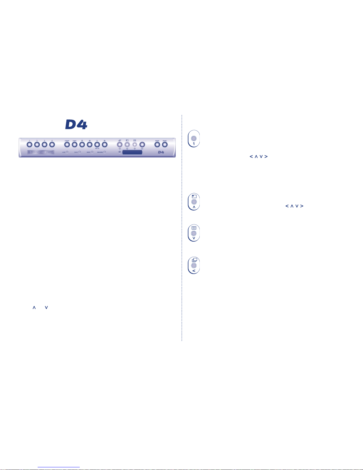
• Appendix 2 - Using the Remote Control 20
What is D4?
D4 is a cost effective and easy to use video multiplexer, digital video recorder,
single channel audio recorder, and network video transmitter in a one box solution.
A video multiplexer?
• Designed with security in mind.
• Easy to use.
• Operates like a traditional multiplexer, not a PC
• All the feature you would expect from a Dedicated Micros multiplexer:
- Main and Spot monitor.
- Quad displays.
- Activity detection.
- Alarms.
- Scheduling.
- Variable record rates.
A digital video recorder?
• Playback and record simultaneously, without affecting recording
• 31 days or more of time-lapse recordings in one box*.
• Instant access to images recorded on the hard disk with no tapes
Single channel audio recorder?
• Record a single channel of audio stream along with the images.
• Microphone and line level audio inputs, and line level outputs.
Network transmission?
• View live and playback images across the network.
• No extra software to buy, Network Viewing software for Windows™ provided.
• Copy images across the network
*Refers to the 160GB model at default settings.
Page 4

ENGLISH
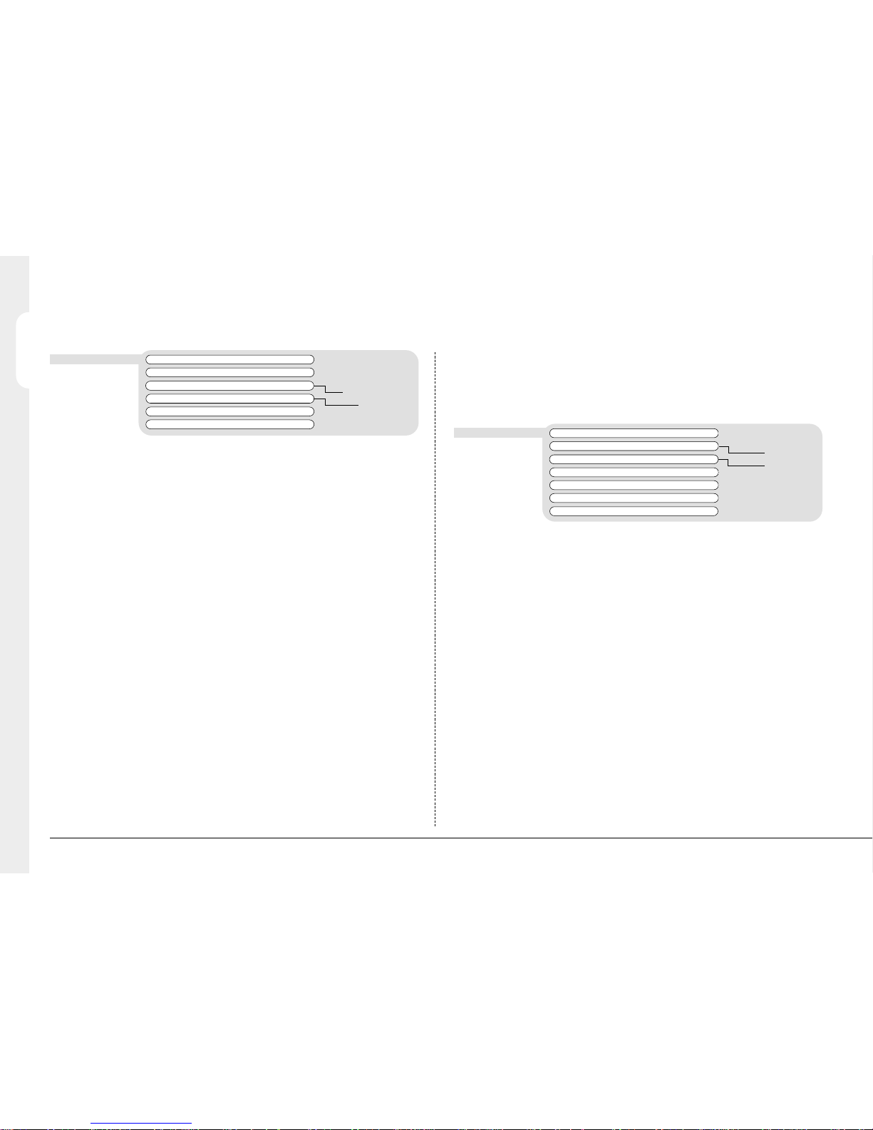
Features:
Auto detect cameras on power up ✔
Auto detect external storage on power up ✔
Default recording ✔
Loop-through connections ✔
Play, record, copy and transmit simultaneously ✔
Real-time quad updates ✔
Hidden camera option ✔
Scheduling ✔
Control via IR remote control ✔
VCR style playback ✔
Full, Quad, and PIP playback ✔
Activity detection ✔
Alarms ✔
Event log with preview window ✔
Record 1 channel of audio in real time ✔
2
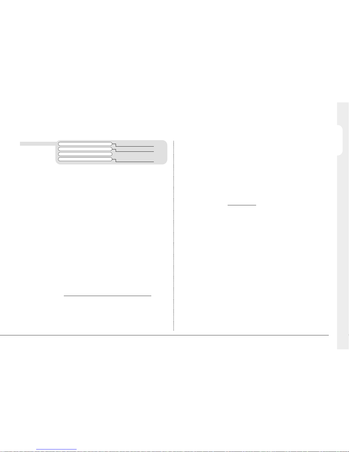
The manual has two parts:
1. An operators card
- giving details of installation and operation.
2. A Setup guide (this document)
- giving details of configuring the D4 and external devices.
Operation
Playback
Events
Audio
Installation Network Viewing
External storage devices
Live viewing ✔
Playback viewing ✔
Up to 5 network users at once ✔
Copy images across networks ✔
E-mail on event activation ✔
Yamaha/Plextor CDR (check for compatible models) ✔
Page 5

ENGLISH
3
Important Safeguards
REGULATORY NOTES FCC AND DOC INFORMATION
(USA and Canadian Models Only)
WARNING: This equipment has been tested and found to comply with the limits
for a Class A digital device, pursuant to part 15 of the FCC rules. These limits are
designed to provide reasonable protection against harmful interference when the
equipment is operated in a commercial environment. This equipment generates,
uses, and can radiate radio frequency energy and, if not installed and used in
accordance with the instruction manual, may cause harmful interference to radio
communications. Operation of this equipment in a residential area is likely to
cause harmful interference in which case the user will be required to correct the
interference at their own expense.
If necessary, the user should consult the dealer or an experienced radio/television
technician for corrective action. The user may find the following booklet prepared
by the Federal Communications Commission helpful: “How to Identify and
Resolve Radio-TV Interference Problems”.
This booklet is available from the US Government Printing Office, Washington,
DC20402, Stock No. 004-000-00345-4.
This reminder is provided to call the CATV system installer’s attention to Art.
820-40 of the NEC that provides guidelines for proper grounding and, in
particular, specifies that the cable ground shall be connected to the grounding
system of the building, as close to the point of cable entry as practical.
CE Mark
This product is marked with the CE symbol and indicates compliance
with all applicable directives.
Directive 89/336/EEC.
A “Declaration of Conformity” is held at Dedicated Micros Ltd.,
11 Oak Street, Swinton, Manchester M27 4FL.
Read Instructions
All the safety and operating instructions should be read before the unit
is operated.
Power Sources
This unit should be operated only from the type of power source
indicated on the manufacturer’s label.
Servicing
Do not attempt to service this unit yourself as opening or removing
covers may expose you to dangerous voltage or other hazards.
Refer all servicing to qualified service personnel.
Ventilation
Ensure unit is properly ventilated to protect from overheating.
To prevent fire or shock hazard, do not expose this equipment to rain or moisture.
The lightning flash with arrowhead symbol within an equilateral triangle is
intended to alert the user of this equipment that there are dangerous voltages
within the enclosure which may be of sufficient magnitude to constitute a risk of
electric shock.
This is a class A product. In a domestic environment this product may cause radio
interference in which case the user may be required to take adequate measures.
WARNING
WARNING
Page 6

4
Installing
BEFORE YOU START:
Check the contents of the box
The following items are included in the box:
❑
IR remote handset
❑
PSU
❑
Mains cable with three pin plug fitted (North America)
❑
Mains cable without plug fitted (other regions)
❑
485-bus cable (with ferrite clamp fitted)*
Choosing a location for installation
D4 is designed to be rack or desk mounted. The following precautions must be
taken when installing D4:
• Openings in the unit’s case are provided for ventilation. To prevent
overheating, these openings should not be blocked or covered.
• When stacking units, ensure there is at least a 1/2" (1.5 cm) gap between
each unit.
• Ensure there is a 1" (3cm) gap on either side of the unit.
• Ensure the unit is not located in an area where it is likely to be subjected to
mechanical shocks.
• The unit should be located in an area with low humidity and a minimum of
dust. Avoid places like damp basements or dusty hallways.
• If using external storage, refer to the manufacturer’s instructions for
placement details.
* When adding 485-bus accessories, the 485-bus cable must be fitted with the ferrite clamp nearest the D4.
A quick overview of digital recording
Digital multiplex recorders work in exactly the same way as analogue
multiplexers except that they use hard disks and digital tape to store video,
instead of VCR tapes.
Analogue recording uses time-lapse recording to extend the length of time
recorded onto 2 or 3-hour tape - recording fewer pictures every second.
Adjusting the number of pictures recorded every second also extends the length
of time recorded onto the hard disk of a D4. However, other factors also
determine the amount of time that can be stored on the disk of a digital
multiplex recorder:
• The image quality
• The record rate
• The hard disk capacity
Image quality
Digital multiplex recorders store images in a compressed format, allowing images
to be recorded more efficiently. The higher the compression, the smaller the file
size, but the image quality will suffer. D4 can compress images between 6KB and
45KB.
Kilobytes and Gigabytes are units of storage:
1GB = 1024 Megabytes (MB)
1MB = 1024 Kilobytes (KB)
With analogue recording, the image quality is dependent on the type of VCR
being used; VHS or S-VHS. D4 allows the image quality to be altered by adjusting
the image size, for example, VHS quality is 14KB, S-VHS is 18KB, and greater than
S-VHS is 25KB*.
Using a larger image size will fill the hard disk faster than a smaller image size, as
more space is required to store it. To achieve the same amount of recording time
when a larger image size is used requires the record rate (PPS) to be reduced.
* Note that as for all digital recording, image quality can vary for different scene types, S-VHS quality may
be 18KB in one scene, but it may be 30KB or more to get the same quality in a scene with more detail.
ENGLISH
Page 7

5
Quick Install
Record rate
The record rate is the amount of pictures recorded to disk in a second, or pictures
per second (PPS). This is a system wide figure, so whether 1 or 4 cameras are
recorded, the record rate remains the same. The update rate per camera can be
worked out using the record rate:
Update rate = No. of cameras
Record rate
A table of common record rates can be found in Appendix 1.
Hard disk capacity
Analogue VCRs use 3-hour tapes which record a finite number of images. Unlike
a VCR, the number of images that can be recorded to a digital multiplex recorder
can be increased by using a larger capacity hard disk. At the time of writing, D4 is
available in 40 and 160GB hard disk sizes.
Using a larger hard disk will allow image quality, recording rate, or recording time
to be increased. For example, a 40GB disk can record for 8 days at the default
settings (24-hour time-lapse mode at S-VHS quality).
Calculating recording time
D4 calculates the recording time automatically when the record rate and image
quality are entered. Alternatively, an interactive record calculator is available for
download from our web site:
www.dedicatedmicros.com
D4 can be installed in as little as 4 steps, and being plug-and-play, cameras will be
detected and recorded automatically.
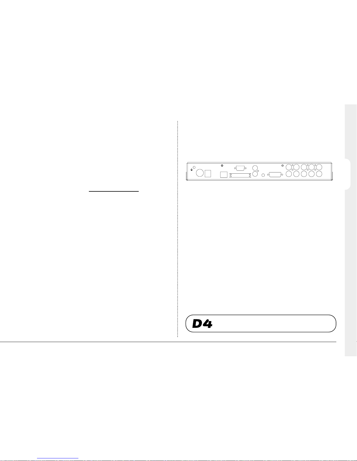
STEP 1. Connect cameras
Connect cameras to the video inputs marked VID1 to VID4. Use the bottom row
of connectors for looping through to other equipment.
STEP 2. Connect monitors
Connect the video output marked MON A to the Main monitor (digital playback
and multiscreens).
Connect the video output marked MON B to the optional Spot monitor (analogue
full-screen images).
STEP 3. Connect the external devices
If external devices need to be connected to D4, go to the next section ‘Connecting external devices’, before proceeding to Step 4.
STEP 4. Connect power
Once the D4 is in its final position and all external devices have been fitted and
powered, connect the PSU to the rear of the unit and apply the power. The power-up
procedure may take up to one minute before D4 can be used.
ENGLISH
will now record all cameras without any further
programming!
B
A
OUT
IN
485 BUSPOWER
NET ALARM/RELAYMIC
SERIAL
SCSI VID 4VID 3VID 2VID 1
MON
LINE
Page 8
6
Connecting External Devices
D4 uses 485-Bus networking to interconnect Dedicated Micros products and
accessories. Storage devices can be connected to the SCSI port.
Devices that can be connected to D4 include:
Storage devices
Alarms and relays
Audio devices
Ethernet networks
Dial-up modems
If you do not require any of the above devices to be connected to D4, move on to
‘Configuring D4’ - Page 9.
Connecting storage devices
Images are recorded to the internal hard disk for instant playback and searching
by the operator. The capacity of the internal disk affects the amount of images
and time that can be recorded. For example, a D4 with a 40GB hard disk can
record for 8 days at a 24-hour time-lapse mode using a 160GB hard disk allows
one month of recording.
The internal hard disk is a temporary storage device as the images are constantly
being overwritten after a certain period of time. If images need to be kept for
longer then external storage is required. The 50-way high density SCSI-2 port on
the rear of the D4 is used to connect to external storage.
Images can be copied from the internal hard disk onto CDR disks for long term
storage. CD’s are ideal for recording relatively small amounts of images such as
events, video clips, or incidents. These images can be played back on any PC with
a CD drive and DM Playback software installed.
The table below shows the recording times at typical recording rates (at S-VHS
image quality, 18KB):
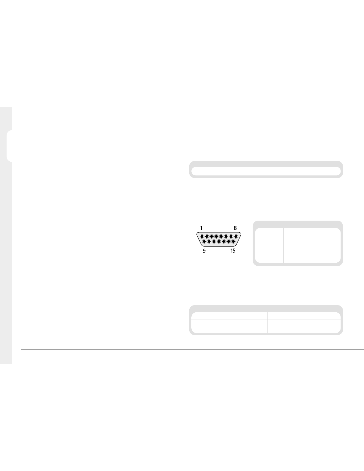
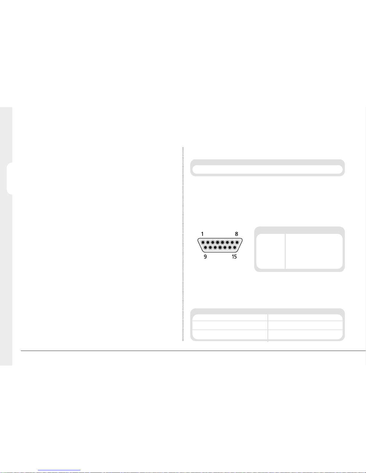
Connecting Alarms and Relays
Dry contact alarms can be wired directly to the alarm connection on the back on
the D4. There are 5 alarm inputs, one for each camera, and a global alarm input.
The alarm connections are as follows:
The polarity of the alarms - normally open or
normally closed, can be set in the ‘Camera
setup’ menu.
The global alarm input is used to set or unset the schedule function.
An alarm trigger performs the following actions:
ENGLISH
1PPS 2PPS 3PPS 6PPS 12PPS 25PPS
CD-R 640MB 9h 46m 4h 49m 3h 12m 1h 36m 48m 23m
Set Unset
Close relay 1. Open relay 1 after 2 seconds.
Display the alarm camera on the main monitor. Resume pre-alarm display after 2 seconds.
Interleave record the alarm camera. Standard record after 2 seconds.
PIN Connection
9 Global alarm
10 Alarm 1
11 Alarm 2
12 Alarm 3
13 Alarm 4
14 GND
(View from plug solder side)
Times indicate all cameras being copied to the CD.
Page 9

ENGLISH
7
Relay connections are as follows:
Important Note: The onboard relays are rated at 24V 500mA, do not attempt to
connect mains power through the relays.
Connecting Audio devices
D4 can record and playback a single stream of audio linked to camera 1. There
are two audio input ports: MIC IN and LINE IN, and an audio output: LINE OUT.
Connecting a microphone to MIC IN.
Connect the microphone into the 3.5mm jack plug labelled MIC IN. It is important
to select the correct type of microphone for connection to the D4. D4 requires an
electret microphone with a sensitivity of –50dBV or better.
Connecting a pre-amplifier to LINE IN.
Where additional microphone gain and/or adjustable gain is required, an external
microphone pre-amplifier with adjustable gain is recommended. A microphone
pre-amplifier will provide a line level 1V pk-pk signal that can be connected to the
RCA socket labelled LINE IN on the D4.
The line level input has the following specification:
Line IN 47kΩ input impedance, 1V pk-pk
Pin Connection Action
1-2 Relay 1 Close on Alarm
3-4 Relay 2 Close on Activity Detection
5-6 Relay 3 Close on Camera fail
7-8 Relay 4 Undefined
Connecting the LINE OUT to an amplifier.
Connected the RCA socket labelled LINE OUT to an external amplifier or powered
loudspeakers.
The line level output has the following specification:
Line OUT 1V pk-pk
Recording audio
Once the microphone or pre-amplifier is connected to the D4, the option to
record audio should be enabled in the menu. See page 17 for details of enabling
audio recording.
It is advised that you test the quality of audio playback, it may be necessary to
increase the gain of the microphone
As the audio is linked to camera 1, it is required that camera 1 be viewed, either
in a full screen or in a quad view during playback to hear the audio.
Connecting to an Ethernet network
D4 can be connected to a standard 10-baseT Ethernet network allowing full
control of the D4 from a remote location.
Network connection
To connect a D4 to a network you will need the following items:
• A spare 10-baseT network point.
• A RJ-45 network cable (CAT5 or equivalent).
• A static IP address and Subnet mask (some networks may also require a
Default gateway, consult the network administrator for advice).
Page 10

ENGLISH
8
To configure the D4 on the network you will need to perform the following steps:
1. Enter the D4 menu (press and hold the menu button).
2. Tap the menu button until the ‘System Options’ page is displayed.
3. Use the cursors to select ‘Network settings’
4. Enter the ‘Network settings’ menu by highlighting ‘Edit’ and pressing the up
or down cursor.
5. Enter the IP address, Subnet mask and Default gateway in the spaces.
Note: The addresses are four sets of three digits, if you have only two digits in
the address insert a 0 before the number i.e. 123.123.123.001
6. Press the menu button to exit the menu.
7. Press camera 1 to accept the changes and reboot the system, or press menu
again to exit without changing the settings.
Viewing images across the network
D4 can use either a web browser or Network Viewing Software to view images
across the network. The Network Viewing Software can be downloaded from the
unit onto your local PC using the network connection.
To download the network viewing software:
1. Open your web browser software on your PC.
2. Enter the IP address of the D4 in the ‘Address’ box in Internet Explorer or
Netscape and press Enter. Remove all preceding 0’s, i.e. 123.123.123.001 in
the D4 should be entered as 123.123.123.1 in the web browser.
3. A web page from the D4 is loaded. Click on the ‘PC viewer application’ icon,
you will be prompted to Save or Run the program.
4. Select ‘Run this application from its current location’.
5. The software will download and install, follow onscreen prompts.
6. The program can be found in Start>Programs>DM Network Viewer.
Details of using the Network Viewing Software can be found in the ‘User Guide’
in the Network Viewing Software folder.
The minimum specification PC for viewing images over a network is:
• 500Mhz CPU
• 64MB RAM
• 4MB video card (capable of 16 million colours)
• Minimum of 800x600 screen resolution
Viewing images across the network using a web browser
It is possible to use Microsoft Internet Explorer (version 5.X and above) and
Netscape Navigator (version 4.7X and above) to view images from a D4. Follow
the instructions above to display the D4 web page, but click on the ‘Web viewer’
icon instead of the ‘PC viewer application’ icon. It will be necessary to enter a
username and password at this point, the default username and password is
user and password.
Note: The web viewer does not have all the features of the Network Viewing
Software, but it is useful if it is not possible to download the software, or if you
want to view the images from an offsite location i.e. via the web.
Viewing images across the network using an Apple Mac or Linux
There is limited support for viewing images using an Apple Mac or Linux based
operating system using Netscape Navigator 4.7X web browser.
Connecting dial-up devices
D4 supports a PPP (Point to Point Protocol) connection from the RS-232 serial
port. This port allows an external Hayes compatible modem to be connected to
the serial port of the D4.
To make a dial-up connection in Windows
®
, Click on Start > Help, and type in
‘Dial Up’ in the search window. A description of making a dial-up connection to
another PC should be displayed.
Note: If a dial-up connection is used, the default PPP address, is 172.17.2.2.
This can be found in ‘Network Settings’ in the ‘System Options’ page.
Important Note: Contact your local DM office for advice on compatible
modems.
Connecting External Devices (continued)
Page 11

ENGLISH
9
Configuring
USING THE MENU
D4 uses a paged menu system to guide the installer through the installation
process.
Entering the menu
There are two types of menus, User and Installer. The user menu will display only
the ‘Time, Date, and Language’ and ‘Schedule’ pages. The installer menu can
display all the menus.
To enter the User menu:
Tap the menu key.
Navigating the menu
The menus are displayed with ‘options’ on the left-hand column and ‘settings’ in
the right hand column. A cursor (highlighted text) can be moved using the
cursor keys on the front panel.
Time, Date & Language
Date 31/04/2002
Time W 12:00
Date format Day, Month
Language English
DST Auto
System Shutdown Disabled
Date
Cursor
Options Settings
To view the next page
Tap the menu key to view the next page.
Tip: Tapping the
orkeys will allow you to go back or forward a page in the menus.
To exit the menu
Press and hold the menu key to exit the menus.
Tip: Cycling though all the menus by tapping the menu key will also exit the menus.
Example of using the menu to change the time:
Time, Date & Language
Date 30/10/2000
Time W 12:00
Date format Day, Month
Language English
DST Auto
System Shutdown Disabled
Time, Date & Language
Date 30/10/2000
Time W 12:00
Date format Day, Month
Language English
DST Auto
System Shutdown Disabled
Date
Time
1. Press and hold the menu key to enter the installer menu. The ‘Time, Date &
Language’ page is displayed.
2. Use the cursor to select the ‘Time’ option on the left-hand side of the menu.
Page 12

ENGLISH
Time, Date & Language
Date 30/10/2000
Time W 12:00
Date format Day, Month
Language English
DST Auto
System Shutdown Disabled
00
Time, Date & Language
Date 30/10/2000
Time W 12:00
Date format Day, Month
Language English
DST Auto
System Shutdown Disabled
30
Time, Date & Language
Date 30/10/2000
Time W 12:00
Date format Day, Month
Language English
DST Auto
System Shutdown Disabled
30
Time, Date & Language Date 01/05/2002
Time S 12:00
Date Format Day, Month Month, Day
Language English Français, Deutsch, Espanól, Italiano
System Shutdown Disabled Enabled
DST Auto Manual
Date
As default, the date is entered DD:MM:YYYY on PAL models and MM:DD:YYYY
on NTSC models, this can be changed using the Date format option below.
Time
The time should be entered in 24 hour format (HH:MM).
Note: Summer and Winter time is signalled by an ‘S’ or ‘W’ next to the time.
Date format
The date format can be changed from Day, Month to Month, Day depending on
regional preference.
Language
The menus can be displayed in a number of languages. Upon selection these are
presented as a dropdown list.
10
Time, Date & Language
3. Use the cursor to highlight the minute settings..
4. Use the cursors to change the settings, in this example 12:30.
5. Use the cursor to return to the left-hand side of the page and select another
option. Or, press and hold menu to exit the menu.
Page 13

ENGLISH
An option is available to view all cameras or selected cameras. All the cameras are
viewed by default. Cameras removed from viewing do not affect the cameras
being recorded.
To change the cameras to be viewed
• Press the ‘ ’ cursor key to change the edit field to ‘Selected cameras’.
• A menu will display the cameras to be viewed.
• Press the camera key to toggle the camera in or out of the viewed sequence.
This camera will be displayed. A filled box denotes cameras that can be viewed.
Note: Cameras removed from view are not displayed on the main or spot monitor
in live or playback mode, multiscreen displays will show a blank segment.
Tip: It is advisable to set a password to stop this setting being altered by
unauthorised personnel.
Camera Viewing
11
System Shutdown
If the D4 needs to be switched off for any reason, the shutdown procedure needs
to be followed:
1. Select ‘Enabled’ in the System Shutdown option.
2. When the pop-up menu appears, press and hold camera 1 for five seconds to
shutdown.
3. The message ‘It is now safe to switch off your unit’ is displayed, switch the D4
off at the wall.
WARNING: Data loss or disk failure may occur if a system shutdown is not
performed before removing power.
DST
Daylight saving time can be adjusted automatically or manually. By default, the
automatic setting will go forward one hour on the last Sunday in March at 01:00,
and one hour back last Sunday in October at 02:00. The default automatic
settings can be changed. If the country where the unit is located doe not use DST
then select manual.
Page 14

ENGLISH
12
Schedule
A schedule can be used to change the record rates and select whether the alarms
or activity detection is enabled.
The schedule gives the option to switch to night settings automatically at a
pre-set time. The schedule is off by default.
On between 18:00 and 09:00
Night Off
Camera Recording
An option is available to record all cameras or selected cameras. All cameras are
recorded by default.
To change the cameras to be recorded:
• Press the ‘ ’ key to change the edit field to ‘Selected cameras’.
• A menu will display the cameras to be recorded.
• Press the camera key to toggle the camera in or out of the record
sequence. A filled box denotes cameras that will be recorded.
Tip: Cameras that are not in the record sequence can still be recorded when
an alarm or activity detection is triggered on that camera.
Camera Recording
Record All cameras
Selected cameras
Page 15

ENGLISH
13
Record Schedule
The record rate and image size determine the amount of time cameras can be
recorded for and the update rate of each camera. Settings can be applied to day,
night, and weekend schedules.
Standard PPS Event PPS Events active
Day 3 3 Both
Alarms
Activity
None
Night 3 3 Both
Alarms
Activity
None
Weekend 3 3 Both
Alarms
Activity
None
Recorded file size 18 KB
Max recording time --:-Total video storage 141GB
Earliest recording 01/10/2001 12.00
Note: The Night and Weekend options are only displayed if a corresponding
Night and Weekend schedule has been configured in the Schedule menu page.
VCR Time-lapse mode (hours) D4 Record rate (PPS)
3 (2) 25 (30)
12 12
24 6
48 3
72 2
168 1
Standard and Event PPS
Select a record rate in pictures per second (PPS) to be recorded across all cameras.
When a single camera is being recorded. The maximum record rate is 25PPS for
PAL and 30PPS for NTSC cameras when a single camera is recorded. When
multiple cameras are recorded the maximum record rate is 18PPS.
The default record rate is 3PPS, this is the equivalent to a VCR in 48-hour timelapse mode. However, because there are only a maximum of 4 cameras the
update rate is faster than a 24-hour time-lapse mode recording 9 or 14 cameras.
To configure D4 to record only events, select the Standard PPS as 0PPS and the
Event PPS to a value you want the events to record at for example, 3PPS. The D4
will then not record any cameras until activity or alarms are triggered, it will then
record the alarmed/activity camera interleaved with the other cameras.
Note: Audio is not recorded when the record rate is at 0PPS.
The table below shows the equivalent record rates of typical VCR time-lapse modes:
Figures in brackets are for NTSC systems.
Page 16

14
You can decrease the update rate by increasing the record rate (PPS), the only
drawback is that the recording time will also decrease.
Events active
Select whether the alarms and activity are on or off for day, night, and weekend
schedules.
When an event is triggered it is automatically interleaved with the non-event
cameras, i.e. if camera 1 has an event, the recording sequence would be
121314121314 rather than the standard sequence of 12341234, effectively
increasing the record speed of camera 1.
Tip: By using event interleave, it is possible to keep the record rate constant but
effectively increase the speed of alarm or activity recording.
Recorded file size
The file or image size affects the quality of the images recorded to disk. A larger
file size has superior picture quality, but will fill the hard disk faster, so less time
will be recorded before the images will be overwritten.
The file size can be set between 6 and 45KB. The table below shows the image
quality at typical file sizes:
Note: The equivalent image quality is representative in most circumstances,
however, camera views with large amounts of image detail may require the file
size to be increased to obtain a similar image quality.
Increasing the file size over 40KB will decrease the maximum record rate to
18PPS, even if a record rate of greater than 18PPS is selected.
Maximum recording time
The maximum recording time is the number of days and hours before the images
are overwritten. The maximum record time is calculated automatically when
the standard or event record rate is highlighted and changed. Note that the
maximum recording time will include the audio, if it is enabled in the System
Options menu page.
Tip: Reducing the file size (KB) or record rate (PPS) can increase the maximum
recording time.
Total video storage
The figure displayed shows the total amount of internal and external disk capacity
available for video storage in GB (Gigabytes).
Earliest recording
The earliest recording displays the date and time of the first image on the disk.
Note: If an event partition is set (in the Event Setup menu) then the earliest
recording could be an event that is older than the first standard recording.
ENGLISH
Update rate (seconds) = Number of cameras =4=0.67 seconds
PPS 3
Image quality File size (KB)
VHS 14KB
S-VHS 18KB
S-VHS+ 25KB
Tip: To work out the update rate per camera - the number of seconds before the
camera is updated. Divide the number of cameras by the record rate (PPS). For
example, 4 cameras with a record rate of 3PPS will be:
Page 17
15
ENGLISH
Event Setup
Auto event copy
Activity detection or alarm events can be automatically copied onto an external
Jaz® disk for reviewing at a later date.
Note: Iomega Jaz® disks may not be available in SCSI format in all countries.
Buzzer
The internal buzzer can be programmed to activate when an alarm, activity
detection, or a camera fail is detected. By default, the buzzer is deactivated.
Note: The camera fail buzzer will continue to activate until the failed camera is
reconnected or replaced. To deactivate the camera fail buzzer on the failed
camera, press and hold the corresponding camera key to enter the Camera Setup
menu and disconnect the camera video input.
Event partition
An event partition can be configured to protect events for longer than using just
the normal recording partition. When an event partition is configured, all events
will be saved to this area. The events are overwritten in a first in last out basis
when the partition is full.
To work out the required event partition size, use the following equation:
Where;
Days = Number of days to record before events are overwritten.
Image size (KB) = The recorded image size in kilobytes.
% Events = The percentage of recordings which are events.
Event PPS = The record rate of event recording (PPS).
For example, If you want to keep events for 5 days before they are overwritten,
alarms are triggered for 25% of the time, image size is 18KB, and the Event PPS
is 6 pictures per second the equation would be:
CAUTION: Specifying an event partition will reduce the disk space and hence
recording time for normal recording.
Status page
A status page giving details of alarms and camera failures can be displayed upon
entering the menus. To display this page select ‘On’.
Event partition (GB) = Days x Image size (KB) x % Events x Event PPS
1111
Event Setup
Auto event copy Off
Buzzer None
Event partition Edit
Status page On
Event partition (GB) = 5 x 18 x 25 x 6 = 12GB
1111
Activity, Alarms, Both
Off
Alarm, Activity, Camera Fail
Page 18
ENGLISH
16
System Options
User password
A password can be set to prohibit unauthorized access to the menu systems.
The default setting is Off.
To set or change the menu password:
1. Use the cursor keys to change the User password to On.
2. When the new password menu is displayed use the camera key numbers to
enter a password - up to eight numbers.
3. Press the menu key to enter the password.
4. When prompted re-enter the password to confirm and press the menu key
when complete.
WARNING: For security reasons, loss of passwords will require the unit to be
returned for the passwords to be reset.
Make a note of your password here __ __ __ __ __ __ __ __
System Options
User password Off
Network settings Edit
IR receiver Enabled
Timed expiry Edit
Factory default Reset
Disabled
Audio recording Off
On
Network Settings
System name D4
Network Enabled
IP address 000.000.000.000
Subnet mask 255.255.000.000
Default gateway 000.000.000.000
1 – 100%
Bandwidth limit 100%
Disabled
PPP address 172.017.002.002
Network settings
This option is used to configure the unit for connection to an Ethernet network or
dial-up. A pop-up box for configuring the network settings is displayed with the
following items:
System name
Each D4 on the network can be given a system name to help identification, the
unit name is displayed in the Network Viewing software. A maximum of 30
characters can be used for the system name. The default unit name is ‘D4’.
Tip: If you do not want the unit to automatically identify itself on a network, use
a ‘#’ symbol as the first character. You will still able to access the unit across the
network by typing in the IP address directly into the Network Viewing software.
Network
This option is used to enable or disable the network option. The network is
enabled by default.
Page 19

ENGLISH
17
Bandwidth limit
The bandwidth used by the D4 can be limited to prevent overloading on slower
networks. The D4 has a 10MB/s connection (10Base-T).
The maximum bandwidth that a D4 will use (5 users viewing images) is 6Mb/s so
any limiting over 60% does not affect the bandwidth used by the D4. The
maximum bandwidth used by one user is approximately 2.5Mb/s
If you want to limit the bandwidth used by the D4 to 1Mb/s set the bandwidth
limit to 10%.
Note: Restricting the bandwidth does not decrease the image quality, but the
update rate of the images over the network will decrease.
IP address, Subnet mask, Default gateway
A unique IP address and a subnet mask must be given to the D4 in order to
communicate with it over a network. On an existing network these are often
obtained from the network administrator. A Default gateway will be required if
the D4 is going to be viewed from a remote location, such as a WAN or dial-up
via a router.
Note: The D4 requires a Static IP address, even if it is connected to a dynamic
(DHCP) network.
PPP address
The PPP (Point to Point Protocol) address is used when a Hayes compatible modem
is connected to the D4. The PPP address must be entered into the Network Viewing
software or Web browser to view images when connected to the D4.
By default, the PPP address is 172.017.002.002 when the TCP/IP address is at its
default setting of 000.000.000.000. The PPP address cannot be changed directly,
but is changed automatically when the TCP/IP address is adjusted.
Audio recording
A single channel of audio can be recorded on the D4, use this menu to enable or
disable audio recording. Audio recording takes up a small amount of storage,
approximately 4KB/s, this is regardless of the record rate (PPS) of the video. When
audio is enabled the record time is affected, check the new record time in the
‘Record Schedule’ menu.
Note: The audio recording is linked to Camera input 1, i.e. audio is only recorded
when camera 1 is recording. Camera 1 must be displayed to play back audio.
IR Receiver
The Infrared remote control option can be enabled or disabled from this menu.
The remote control mimics the front panel control of the D4. The remote control
does not allow the configuration of the menus.
When the IR receiver is enabled the IR LED on the D4 is solid green, when it is
disabled the IR LED switches to solid amber. The LED flashing green signifies an
IR signal being received.
Please refer to Appendix 2 for details of using the remote control.
Timed expiry
The timed expiry option allows images to be only held for a selected number of
days or hours. Images on the disk which are older than this time are not accessed.
By default there is no timed expiry.
Factory default
Use this option to return all settings to the factory condition.
Page 20

ENGLISH
18
Camera Setup
Title
Each camera title can be up to 12 characters long.
Input termination
The input termination does not auto detect by default, the termination must be set
manually On (default) or Off. The termination must be set to Off if the camera is
looped through to other equipment.
Camera type
Colour and monochrome cameras are detected automatically, allowing colour/mono
switching cameras to be connected. The camera type can be manually configured
as Colour or Mono if necessary.
Alarm input/Polarity
Select whether the alarm connected is Normally open (default),
Normally closed, or Off.
Colour adjust
When the colour bar is selected, press to reduce, and to increase the colour.
Note: this option is not displayed if the camera is set as monochrome.
Contrast adjust
When the contrast bar is selected, press down to reduce, and up to increase
the contrast.
Camera video input
This option is only displayed when a camera has failed or is offline. Select
disconnect whilst the camera is offline to prevent the camera fail message and
alarm being triggered.
Tip: This menu can be entered directly by pressing and holding a camera key.
Activity Camera Setup
Activity detection is used to record more images to disk from cameras that have
activity. The sensitivity of activity can be adjusted and areas can be masked off
according to the scene type.
Detection
Select whether activity detection is on or off for the selected camera.
Sensitivity
There are 5 levels of sensitivity for activity detection.
Select the sensitivity level which matches the camera’s placing. Cameras sited
outdoors where there may be a lot of background movement, such as trees or
rain, should be set to Outdoor high or Outdoor low sensitivity. Cameras sited
indoors where there is very little background movement should be set to Indoor
high, Indoor low, or very low sensitivity.
Activity grid
An 8 x 16 grid is used to mask areas where activity detection is enabled. When
the grid is displayed, use the cursor keys to move the cursor to the desired
location and press a camera key to toggle the block on (white dot) or off.
Activity test
Use this option to test and tune the sensitivity and activity grid set up for each
camera. When activity is detected on the camera a white dot is displayed. Press
the mode/menu key to exit the test.
Activity Camera Set-Up Detection Off On
Sensitivity Outdoor high Outdoor low, very low, Indoor high, Indoor low
Activity grid Setup
Activity test Walk test
Camera Set-Up Title CAMERA 1
Input termination Auto detect Off, On
Camera type Auto detect Off, On
Alarm input/Polarity Normally open Normally closed, Off
Colour adjust
Contrast adjust
Camera video input Connected Disconnected
Page 21
Operating
PLAYING BACK IMAGES FROM THE DISK
Playback
• To playback images tapto rewind to the desired location and then press.
• When in playback, tap
orto search rewind or fast forward, multiple taps will
increase the search speed.
• Tap
II
to pause the current image. Tappingorwhilst paused will frame
advance or rewind.
Goto time
Press and hold(goto) to play back from a specific time or date.
Enter the required time and date, and press
.
Tip: The images are updated in the background automatically when the time and date is adjusted.
Exit playback
Tap the mode key to exit playback mode, the Play LED will distinguish.
USING THE EVENT LOG
Alarms and activity detection are tagged and stored in the event log for easy retrieval. Each
event is labelled with event type (alarm or activity), its camera title, time, and date. To view
an event from the event log:
• Tap event to display the event log.
• Use and to select the event required, the selected event is displayed in
the preview window.
•Tap
to view the event in full screen.
• Tap mode to exit the Event log.
VIEWING SINGLE CAMERAS
Full
Pressing a camera key will display a full screen image of that camera.
Zooming an image
Press the same camera key to toggle zoom on and off.
When zoom is enabled, use to scroll around the image
Note: Zoom is not available in playback mode.
Freezing an image
Double tap the camera key toggle freeze frame on or off.
VIEWING MULTIPLE CAMERAS
Picture in Picture
Press the PIP key to toggle the main and PIP image.
Press and hold the PIP key to edit the display, use to select the segment,
press the required camera key to fill that segment.
Press menu to exit.
Quad
Press the QUAD key to switch to quad display.
Note: The quad display cannot be edited.
SEQUENCING CAMERAS
Sequence
Press the sequence key to toggle the main monitor sequence on or off.
Press and hold the sequence key to edit the sequence.
Use the camera keys to include or remove cameras from the sequence.
Press menu to exit.
Note: The spot monitor sequence can only be activated or edited in spot mode
VIEWING CAMERAS ON THE SPOT MONITOR
Press the mode key to toggle ‘spot’ mode, indicated on the main monitor and the front
panel LED.
Press a camera key to display that camera on the spot monitor or tap the sequence key to
sequence the cameras.
Page 22

CDR Archive
CD Type – 656MB CD
CD Use [--+---------------] 4% Full
From To Cameras
12:00 01/12/01 12:01 01/12/01 123456789
Next 12:01 01/12/01 to 12:02 01/12/01
Add next Clear list Create CD Verify CD
Add next
Copy Images
Copy destination CD0: SCSI Yamaha
Copy from time 12:01:00 01/12/2001
Copy to time 12:02:00 01/12/2001
Copy Selected cameras
1 2 3 4 5 6 7 8
■ ■ ■ ■ ❏ ❏ ❏ ❏
9 10 11 12 13 14 15 16
❏❏ ❏❏ ❏ ❏ ❏❏
Selected cameras
COPYING IMAGES TO CD
To copy images to the external CD writer (if connected):
1. Insert a blank CDR or pre-formatted CD-RW into the CD writer.
2. Go to the first point from where you want to copy images from using the
key or the
GOTO function,
3. Press COPY.
4. Use the
,orkeys to go to the last image you want to copy, or use the GOTO key.
5. Press COPY again. The following screen is displayed:
Copy destination This is the name and type of CD drive connected to
the SCSI port.
Copy from time Select the time you wish to copy images from.
Copy to time Select the time you wish to copy images to.
Copy Select ‘All cameras’ or individual cameras to copy using the camera keys
(filled boxes are selected cameras, unfilled boxes are not selected).
TIP: You can display this page directly by pressing and holding the COPY key and enter the
copy time manually, rather than the first and last image.
Once the ‘Copy images’ page is complete, press the menu key to display the following menu:
Add next Add the selected times to the archive list.
Clear list Removes all entries from the list.
Create CD Creates a CD with the images in the list.
Verify CD Verify that the CD has been written correctly.
To select any of the above options, highlight the option and tap menu.
To add images to the CD:
1. Select ‘Add next’ and press the menu key to add the displayed time to the list.
2. You may wish to add more images to the CDR archive if the CD is not yet full. To select
more images to add to the list press
to return to the ‘Copy images’ screen.
3. Once all the required images are added to the archive list, select ‘Create CD’ and press
the menu key to create the CD. The CD will eject once the CD has been created.
4. The CD can be reinserted and verified if required using the ‘Verify CD’ option.
5. Press and hold the menu key to exit the CDR Archive option.
This menu displays the archive list of images to be copied to the CD, the ‘CD Use’ bar
indicates the how much space is available on the CD, once it reaches 100% no more images
can be added to the archive.
Page 23

ENGLISH
19
Appendix 1
Selecting record rates
D4 continuously records to its internal hard disk. The amount of time the hard disk will record for depends on a number of factors:
Hard disk capacity (disk size in Gigabytes)
Image quality (file size in Kilobytes)
Record rate (pictures per second)
The table below shows the recording rates for different image quality and hard disk sizes.
Using the table:
1. Select the internal hard disk size on the left.
2. Select the number of hours to record across the top.
3. Select the image quality (VHS, S-VHS, or S-VHS+).
4. Read down the table for the record rate in pictures per second (PPS).
An interactive record rate calculator is available on our website at www.dedicatedmicros.com
Record 24 hours 48 hours 72 hours 168 hours 336 hours 744 hours
duration (7 days) (14 days) (31 days)
Image quality VHS S-VHS S-VHS+ VHS S-VHS S-VHS+ VHS S-VHS S-VHS+ VHS S-VHS S-VHS+ VHS S-VHS S-VHS+ VHS S-VHS S-VHS+
14K 18K 25K 14K 18K 25K 14K 18K 25K 14K 18K 25K 14K 18K 25K 14K 18K 25K
40GB 17PPS 17PPS 17PPS 15PPS 12PPS 8PPS 10PPS 8PPS 5PPS 4PPS 3PPS 2PPS 2PPS 1PPS 1PPS 1PPS - -
160GB 17PPS 17PPS 17PPS 17PPS 17PPS 17PPS 17PPS 17PPS 17PPS 17PPS 14PPS 10PPS 9PPS 7PPS 5PPS 4PPS 3PPS 2PPS
Page 24

20
ENGLISH
Appendix 2
Using the remote control
The remote control included with the D4 operates like the front panel, see the
operator card for details.
To use the remote control the ‘IR receiver’ option need to enabled in the ‘System
Options’ menu page.
1 2 3 4
5 6 7 8
9 10
UNIT
SELECT
MODE
HOLD SPOT EVENT GOTO
11 12
13 14 15 16
The remote control provides the following functions:
UNIT SELECT Not applicable for D4.
MODE Press to toggle Spot mode on and off,
or to return to Live mode when
playing back.
HOLD Toggle freeze frame On and Off.
SPOT Toggle Spot mode on and off, Selects
operation of the spot monitor.
EVENT Press to display the Event log.
GOTO Press to display the Goto time option.
1 – 16 Camera selection keys.
Use to control the cursor in menus,
or scroll around the screen when in
zoom mode.
Attention: Ne jamais
déplacer l'unité lorsque celle-ci
se trouve sous tension.
Page 25

1
Introduction
Sommaire
• Introduction 1
• Caractéristiques 2
• Précautions importantes 3
• Installation du D4 4
• Installation rapide 5
• Raccordement de dispositifs externes 6
- Connexion de dispositifs de stockage 6
- Connexion d’alarmes et de relais 6
- Connexion de dispositifs audio 7
- Enregistrement audio 7
- Connexion à un réseau Ethernet 7
- Connexion de dispositifs de transmission 8
• Configuration du D4 9
- Utilisation des menus 9
- Heure, date et langue 10
- Visualisation d’images issues de caméras 11
- Programmation horaire 12
- Enregistrement d’images issues de caméras 12
- Programmation d’enregistrement 13
- Paramétrage événement 15
- Options système 16
- Paramétrage caméra 18
- Paramétrage activité caméra 18
• Annexe 1 - Sélection de la vitesse d’enregistrement 19
• Annexe 2 - Utilisation de la télécommande 20
Le D4 en quelques mots
Le D4 est un équipement d’utilisation très facile et d’un excellent rapport qualité/prix.
Il regroupe dans un seul boîtier un multiplexeur vidéo, un enregistreur vidéo numérique,
un enregistreur audio mono-canal et un émetteur vidéo en réseau.
Multiplexeur vidéo
• Conçu avec une orientation dédiée à la sécurité
• Simple d’utilisation
• Fonctionnement semblable à celui d’un multiplexeur traditionnel et non à
celui d’un ordinateur
• Possède toutes les fonctionnalités attendues de la part d’un multiplexeur
Dedicated Micros :
- Moniteur principal et moniteur d’observation (“spot”)
- Affichage en quadravision
- Détection d’activité
- Alarmes
- Programmation horaire
- Vitesses d’enregistrement variables
Enregistreur vidéo numérique
• Possibilité de lecture et d’enregistrement simultanés, sans que l’enregistrement
en cours n’en soit affecté
• Possibilité de durée d’enregistrement sur plus de 31 jours en mode “Time-lapse”*
• Accès instantané aux images enregistrées sur le disque dur, sans devoir recourir
à des cassettes
Enregistreur audio mono-canal
• Enregistrement sur un canal du flux audio associé aux images
• Entrées audio de type microphone et de type niveau ligne, sorties audio de
type niveau ligne
Transmission réseau
• Possibilité de visualisation en temps réel et de lecture d’images enregistrées
sur le réseau
• Aucun logiciel supplémentaire nécessaire. Le logiciel de visualisation en réseau
pour WindowsTM est fourni.
• Possibilité de copie d’images via le réseau
* Pour le modèle 160 Go fonctionnant avec les paramètres définis par défaut.
FRANÇAIS
Page 26

FRANÇAIS
Caractéristiques :
Détection automatique de la présence des caméras lors ✔
de la mise sous tension
Détection automatique de la présence de dispositifs ✔
d’archivage externes lors de la mise sous tension
Enregistrement par défaut ✔
Raccordements en boucle ✔
Lecture, enregistrement, archivage et transmission simultanés ✔
Mises à jour en quadravision et en temps réel ✔
Option de masquage des caméras ✔
Programmation horaire ✔
Télécommande infrarouge ✔
Fonctionnement comparable à celui d’un magnétoscope traditionnel ✔
Modes de lecture “Plein écran”, “Quadravision” et “PIP” ✔
Détection d’activité ✔
Alarmes ✔
Mémoire d’événements (avec fenêtre de prévisualisation) ✔
Enregistrement d’un canal audio en temps réel ✔
2
Ce guide est scindé en deux parties :
1. Un guide de référence rapide
- Détails sur l’installation et le fonctionnement
2. Un guide complet d’installation et de programmation
(ce document)
- Description détaillée de la configuration du D4 et des dispositifs externes
Fonctionnement
Lecture
Evénements
Audio
Installation Visualisation réseau
Dispositifs de stockage externes
Visualisation en temps réel ✔
Visualisation en lecture ✔
Jusqu’à 5 utilisateurs réseau simultanés ✔
Copie d’images via le réseau ✔
Envoi d’e-mail dès la survenance d’un événement ✔
Yamaha / Plextor CDR (vérifier les modèles compatibles) ✔
Page 27
FRANÇAIS
3
Précautions importantes
REMARQUES CONCERNANT LA REGLEMENTATION FFC ET
INFORMATIONS DOC
(Modèles américains et canadiens uniquement)
ATTENTION : cet équipement a été testé et s’avère conforme aux limites d’un
équipement numérique de classe A, conformément à la partie 15 des règles FFC.
Ces limites sont conçues afin de fournir une protection raisonnable contre les
interférences parasites lorsque l’équipement fonctionne dans un environnement
commercial. Cet équipement génère, utilise et peut rayonner des fréquences
radio. S’il n’est pas installé et utilisé conformément aux instructions contenues
dans ce manuel, ce dispositif peut perturber les communications radio.
L’exploitation de cet équipement dans une zone résidentielle est susceptible
d’entraîner des interférences préjudiciables. Dans ce cas, l’utilisateur sera tenu
de supprimer lesdites interférences à ses frais.
Si nécessaire, il devra consulter le distributeur ou un technicien expérimenté en
radio/télévision pour prendre les mesures correctives qui s’imposent. L’utilisateur
peut consulter le guide de la commission fédérale américaine des communications
(FCC) “Comment identifier et résoudre les problèmes d’interférences radio/TV”.
Ce guide est disponible auprès de l’imprimerie du gouvernement américain sous
le N° 004-000-00345-4 à l’adresse suivante : US Government Printing Office,
Washington, DC20402.
Ce rappel a pour objet d’attirer l’attention de l’installateur de systèmes de
télédistribution sur l’article 820-40 du NEC qui fournit les lignes directrices
concernant la mise à la terre correcte des produits et qui spécifie précisément
que le câble de mise à la terre doit être relié à la ligne de terre de l’immeuble,
le plus près possible du point d’entrée du câble.
Marquage CE
Ce produit porte le symbole CE qui indique sa conformité à la
directive applicable 89/336/CEE.
Une copie de la “Déclaration de conformité” est disponible
chez Dedicated Micros Ltd., 11 Oak Street, Swinton,
Manchester M27 4FL, GB.
Lire les instructions
Lisez avec attention toutes les instructions de sécurité et d’exploitation
avant de faire fonctionner l’équipement.
Sources d’alimentation
Cet équipement doit être alimenté uniquement avec la tension indiquée
sur l’étiquette du fabricant.
Réparation
Ne pas essayer de réparer soi-même cet équipement car l’ouverture ou
le retrait des capots peut exposer l’utilisateur à des tensions dangereuses
ou à d’autres risques. La maintenance de cet appareil doit être confiée
à un personnel qualifié.
Ventilation
Afin de le protéger contre les surchauffes, s’assurer que l’équipement est
bien ventilé.
Afin d’éviter tout danger d’incendie ou de choc électrique, ne pas exposer cet
appareil à la pluie ou à l’humidité. Le symbole de l’éclair contenu dans un triangle
équilatéral prévient l’utilisateur que des tensions dangereuses sont présentes
à l’intérieur du boîtier et indique que l’amplitude de ces tensions est telle qu’elle
peut constituer un risque de choc électrique.
Cet appareil est un équipement de classe A. Utilisé dans un environnement
domestique, il peut être à l’origine d’interférences radio. Dans ce cas,
l’utilisateur sera tenu de supprimer lesdites interférences lui-même en prenant
les mesures nécessaires.
ATTENTION
ATTENTION
Page 28

4
Installation du
AVANT DE COMMENCER
Bien vérifier le contenu de l’emballage
L’emballage doit contenir les éléments suivants :
❑
Télécommande infrarouge
❑
Bloc d’alimentation
❑
Cordon secteur avec prise trois plots raccordée (Amérique du Nord)
❑
Cordon secteur sans prise (autres pays)
❑
Câble bus 485 (avec bloc ferrite raccordé)*
Sélectionner un emplacement pour l’installation
Le D4 est conçu pour être monté en rack ou sur table. Lors de son installation,
il est important de respecter les précautions suivantes :
• Les ouvertures présentes sur le boîtier de l’équipement sont destinées à assurer
sa ventilation. Afin d’éviter tout risque de surchauffe, ces ouvertures ne doivent
en aucun cas être recouvertes ou obstruées.
• Si plusieurs équipements doivent être empilés, s’assurer qu’un espace d’au
moins 1,5 cm reste libre entre chacun d’eux.
• S’assurer qu’un espace d’au moins 3 cm reste libre de chaque côté de
l’équipement.
• Vérifier que l’équipement ne se trouve pas dans une zone où il est susceptible
de subir des chocs mécaniques.
• Il est préférable que l’équipement soit placé dans un endroit peu humide et
quasiment sans poussière. Eviter par conséquent les sous-sols ou les halls.
• En cas d’utilisation d’un support de stockage externe, se reporter aux
instructions du fabricant pour la mise en œuvre du matériel.
* Si des accessoires bus 485 doivent être ajoutés, il est impératif que le câble bus 485 soit raccordé au bloc
ferrite le plus proche du D4.
Généralités sur l’enregistrement numérique
Un enregistreur multiplex numérique fonctionne exactement de la même manière
qu’un multiplexeur analogique, mis à part que les informations vidéo sont
stockées sur des disques durs et des cartouches numériques et non pas sur des
cassettes vidéo.
L’enregistrement analogique utilise le mode “Time-lapse” afin d’étendre la durée
enregistrable sur une cassette de 2 ou 3 heures (c’est-à-dire qu’il emmagasine
moins d’images à la seconde).
Cette méthode permet également d’accroître la durée enregistrée sur le disque
dur du D4. Cependant, avec un enregistreur multiplex numérique, il existe
d’autres facteurs qui influent sur cette durée :
• La qualité des images
• La vitesse d’enregistrement
• La capacité du disque dur
Qualité d’image
Un enregistreur multiplex numérique stocke les images sous une forme compressée,
permettant ainsi d’améliorer l’efficacité de l’enregistrement. Plus la compression est
importante, plus la taille du fichier est réduite, mais la qualité de l’image est évidemment
moindre. Avec le D4, la compression des images peut varier entre 6 et 45 ko.
Les capacités de stockage sont exprimées en kilooctets et en Gigaoctets :
1 Go = 1024 Megaoctets (Mo)
1 Mo = 1024 kilooctets (ko)
Avec l’enregistrement analogique, la qualité de l’image dépend du type de cassette
vidéo utilisé, VHS ou S-VHS. Avec le D4, la qualité varie selon la taille d’image
sélectionnée. A titre d’exemple, la qualité VHS correspond à un fichier de 14 ko,
le S-VHS à un fichier de 18 ko et pour une qualité supérieure au S-VHS, la taille
du fichier est de 25 ko*.
Le fait d’utiliser une taille de fichier image plus importante a pour conséquence de
remplir le disque dur plus rapidement, étant donné que chaque image occupe plus
d’espace. Pour pouvoir, dans ce cas, conserver la même durée d’enregistrement,
il est nécessaire de réduire la vitesse d’enregistrement (ips).
* Il est à noter que pour tout enregistrement numérique, la qualité d’image peut varier selon les différents
types de scènes. Ainsi, la qualité S-VHS peut correspondre à une fichier de 18 ko pour une scène et à un
fichier de plus de 30 ko pour la même qualité concernant une autre scène avec plus de détails.
FRANÇAIS
Page 29
5
Installation rapide
Vitesse d’enregistrement
Cette vitesse correspond au nombre d’images enregistrées sur le disque en une
seconde (unité de valeur en images par seconde / ips). Il s’agit d’un paramètre système
qui reste le même, quel que soit le nombre de caméras (de 1 à 4) prévu pour
l’enregistrement. En revanche, le taux de rafraîchissement propre à chaque caméra
varie selon la vitesse d’enregistrement et conformément à la formule suivante :
Taux de rafraîchissement = Nombre de caméras
Vitesse d’enregistrement
Un tableau regroupant les vitesses d’enregistrements communes est fourni en
annexe 1.
Capacité du disque dur
Les magnétoscopes analogiques utilisent des cassettes 3 heures qui autorisent
l’enregistrement d’un nombre limité d’images. Avec un enregistreur numérique
multiplex, cette quantité d’images peut être augmentée grâce à l’utilisation d’un
disque dur de plus grande capacité. A l’heure actuelle, le D4 est disponible avec
des disques durs de 40 et 160 Go.
L’augmentation de la capacité du disque dur permet d’accroître aussi bien la
qualité des images que la vitesse d’enregistrement et la durée de ce dernier.
Par exemple, un disque de 40 Go permet d’enregistrer jusqu’à 8 jours avec les
paramètres par défaut (mode “Time-lapse” 24 heures en qualité S-VHS).
Calcul de la durée d’enregistrement
Le D4 effectue automatiquement le calcul de la durée d’enregistrement dès
que les données relatives à la vitesse et à la qualité d’image sont saisies.
Alternativement, il est possible de télécharger un utilitaire de calcul interactif
à partir de notre site Internet :
www.dedicatedmicros.com
Le D4 peut être installé en 4 étapes. Etant donné qu’il s’agit d’un équipement “plug
and play”, il est prêt à fonctionner dès que le raccordement est terminé : les caméras
sont détectées et leurs images peuvent être enregistrées automatiquement.
ETAPE 1. Connexion des caméras
Raccorder les caméras sur les entrées vidéo repérées VID1 à VID4. Utiliser la
rangée inférieure de connecteurs pour établir une liaison en boucle vers d’autres
équipements.
ETAPE 2. Connexion des moniteurs
Raccorder la sortie vidéo repérée MON A sur le moniteur principal (pour la lecture
numérique et la visualisation multi-écrans).
Raccorder la sortie vidéo repérée MON B sur le moniteur d’observation optionnel
(visualisation d’images analogiques en mode plein écran).
ETAPE 3. Raccordement de dispositifs externes
S’il est nécessaire de connecter des dispositifs externes au D4, se reporter au
paragraphe “Raccordement de dispositifs externes” se trouvant à la page suivante
avant de passer à l’étape 4.
ETAPE 4. Connexion de l’alimentation secteur
Une fois le D4 installé sur son emplacement définitif et tous les appareils externes
raccordés et mis sous tension, connecter le bloc d’alimentation à l’arrière de l’appareil
et mettre celui-ci en marche. La procédure de mise sous tension peut prendre jusqu’à
une minute avant que le D4 puisse être utilisé.
FRANÇAIS
D4 est maintenant prêt à enregistrer les images issues
de toutes les caméras, en mode “Time-lapse” 24 heures,
sans qu’aucune autre programmation ne soit nécessaire !
B
A
OUT
IN
485 BUSPOWER
NET ALARM/RELAYMIC
SERIAL
SCSI VID 4VID 3VID 2VID 1
MON
LINE
Page 30
6
Raccordement de dispositifs externes
Le D4 utilise un mode de mise en réseau par bus 485 pour interconnecter les produits
et accessoires Dedicated Micros. Des dispositifs de stockage peuvent être connectés au
port SCSI.
Les dispositifs pouvant être associés au D4 sont entre autres :
Dispositifs de stockage
Alarmes et relais
Dispositifs audio
Réseaux Ethernet
Modems à transmission téléphonique
Si aucun de ces dispositifs ne doit être connecté au D4, se reporter directement
au paragraphe “Configuration du D4”, page 9.
Connexion de dispositifs de stockage
Les images sont enregistrées directement sur le disque dur interne, permettant
à l’opérateur d’effectuer une lecture ou une recherche instantanée. La capacité
du disque détermine la quantité d’images enregistrables et, par conséquent,
la durée d’enregistrement possible. Par exemple, un D4 équipé d’un disque dur
de 40 Go peut enregistrer pendant 8 jours au mode “Time-lapse” 24 heures.
De même, un D4 pourvu d’un disque dur de 160 Go peut enregistrer pendant
un mois à ce même mode.
Le disque dur interne constitue un dispositif de stockage temporaire puisque les
images enregistrées sont, après une certaine période, remplacées par de nouvelles.
Si certaines images nécessitent d’être conservées plus longtemps, il faut avoir
recours à un dispositif de stockage externe. Celui-ci doit être connecté au port
SCSI-2 haute densité avec connecteur 50 broches situé à l’arrière du D4.
Pour un stockage de longue durée, les images doivent être copiées sur des CDR. Les
CD représentent en effet un support idéal pour l’enregistrement de petites quantités
d’images telles que des événements, des clips vidéo ou des incidents. Les images
ainsi copiées sur CD peuvent alors être lues à partir de n’importe quel ordinateur
équipé d’un lecteur de CD et sur lequel le logiciel de visualisation DM a été installé.
Le tableau ci-dessous présente les durées d’enregistrements sur CD aux vitesses
d’enregistrements types (qualité d’images de type S-VHS, 18 ko) :
Connexion d’alarmes et de relais
Les contacts secs d’alarmes peuvent être raccordés directement sur les entrées
d’alarme se trouvant sur le panneau arrière du D4. Cinq entrées d’alarme sont
disponibles (une pour chaque caméra plus une pour les alarmes générales).
Les broches de raccordement se présentent comme suit :
La polarité des alarmes (normalement ouverte ou normalement fermée) peut être
paramétrée via le menu "Paramétrage caméra".
L’entrée “Alarme générale” permet d’activer ou de désactiver la fonction
“Programmation horaire”. Le déclenchement d’une alarme peut provoquer
l’exécution des actions suivantes :
FRANÇAIS
1IPS 2IPS 3IPS 6IPS 12IPS 25IPS
CD-R 640 Mo 9h 46m 4h 49m 3h 12m 1h 36m 48m 23m
Activation Désactivation
Fermeture du relais 1 Ouverture du relais 1 après 2 secondes
Affichage des images de la caméra Retour aux images affichées
en alarme sur le moniteur principal avant l’alarme après 2 secondes
Enregistrement entrelacé des images Retour à un enregistrement
de la caméra en alarme normal après 2 secondes
Broche Connexion
9 Alarme globale
10 Alarme 1
11 Alarme 2
12 Alarme 3
13 Alarme 4
14 MASSE
(Vue du côté de la soudure)
Ces durées correspondent à une situation dans laquelle les images
de toutes les caméras sont copiées sur le même CD.
Page 31

FRANÇAIS
7
Les connexions des contacts de relais sont les suivantes :
Remarque importante : les caractéristiques des contacts de relais étant de
24 V / 500 mA, ne pas raccorder l’alimentation secteur sur ceux-ci.
Connexion de dispositifs audio
Le D4 peut effectuer l’enregistrement et la lecture d’un canal audio unique lié à
la caméra 1. Il existe deux entrées audio (“MIC IN” et “LINE IN”) et une sortie
audio (“LINE OUT”).
Connexion d’un microphone sur l’entrée “MIC IN”
Brancher le microphone grâce à la prise jack 3,5 mm repérée “MIC IN”. Il est
important de sélectionner le type correct de microphone. Le D4 nécessite un
microphone Electret ayant une sensibilité d’au moins -50 dBV.
Connexion d’un préamplificateur sur l’entrée “LINE IN”
Lorsque le gain du microphone doit être supérieur et/ou lorsque celui-ci doit être
réglable, un préamplificateur externe avec niveau de gain ajustable est nécessaire.
Un préamplificateur de microphone délivre un signal au niveau ligne de 1 V crête
à crête. Il peut être connecté à la prise RCA repérée “LINE IN” du D4.
L’entrée ligne a les caractéristiques suivantes :
LINE IN Impédance 47 kΩ / 1 V crête à crête
Broche Connexion Action
1-2 Relais 1 Fermé sur alarme
3-4 Relais 2 Fermé sur détection d’activité
5-6 Relais 3 Fermé sur défaillance de la caméra
7-8 Relais 4 Non défini
Connexion de la sortie “LINE OUT” sur un amplificateur
Brancher la prise RCA repérée “LINE OUT” sur un amplificateur externe ou sur des
enceintes amplifiées.
La sortie ligne a les caractéristiques suivantes :
LINE OUT 1 V crête à crête
Enregistrement audio
Une fois le microphone ou le préamplificateur raccordé au D4, l’option
d’enregistrement audio doit être activée dans le menu. Se reporter à la page
17 pour de plus amples informations sur l’activation de l’enregistrement audio.
Il est conseillé de tester la qualité de la lecture audio car il peut s’avérer nécessaire
d’augmenter le gain du microphone.
Les données audio étant liées à la caméra 1, il est nécessaire de visualiser les
images issues de cette caméra (soit au mode plein écran, soit en quadravision)
pour pouvoir entendre l’audio.
Connexion à un réseau Ethernet
Le D4 peut être connecté à un réseau Ethernet 10-baseT standard afin de
permettre une prise de contrôle totale de celui-ci à distance.
Connexion au réseau
Pour connecter le D4 à un réseau, les éléments suivants sont nécessaires :
• Un point de connexion 10-baseT libre
• Un câble réseau RJ-45 (catégorie 5 ou équivalent)
• Une adresse IP statique et une valeur de masque de sous-réseau (certains
réseaux peuvent également nécessiter une passerelle par défaut. Consulter
l’administrateur de réseau pour obtenir plus d’informations à ce propos).
Page 32

FRANÇAIS
8
Procéder comme suit pour configurer le D4 sur un réseau :
1. Accéder au menu principal de programmation du D4 (en pressant et en
maintenant enfoncée la touche “menu”).
2. Appuyer plusieurs fois sur la touche “menu” jusqu’à ce que la page
“Options système” s’affiche.
3. Utiliser les touches curseurs pour sélectionner l’option “Paramètres réseau”.
4. Entrer dans le menu “Paramètres réseau” en mettant l’option “Edit” en
surbrillance et en appuyant sur la touche curseur vers le haut ou vers le bas.
5. Saisir l’adresse IP, la valeur du masque de sous-réseau et la valeur de passerelle
par défaut dans les champs correspondants. Remarque : les adresses sont
constituées de quatre groupes de trois chiffres. S’il n’existe que deux chiffres
dans l’adresse, ajouter un 0 avant le nombre concerné.
6. Presser la touche “menu” pour quitter le menu.
7. Presser la touche “Caméra 1” pour valider les modifications et relancer le
système ou appuyer à nouveau sur la touche “menu” pour quitter sans
modifier les paramètres.
Visualisation d’images sur le réseau
Pour visualiser des images sur le réseau, le D4 peut utiliser soit un navigateur
Internet, soit un logiciel prévu à cet effet. Ledit logiciel peut être téléchargé du
D4 vers un ordinateur local en utilisant la connexion réseau.
Procéder comme suit pour télécharger le logiciel de visualisation en réseau :
1. Lancer le navigateur Internet sur l’ordinateur.
2. Saisir l’adresse IP du D4 dans le champ “Adresse” d’Internet Explorer ou de
Netscape et appuyer sur la touche “Entrée”. Supprimer tous les “0” précédant
d’autres chiffres. Par exemple, l’adresse IP “123.123.123.001” du D4 doit être
saisie sous la forme “123.123.123.1” dans le navigateur Internet.
3. Une page Web est chargée du D4. Cliquer sur l’icone “PC Viewer Application”
(visualisation sur ordinateur). Un message invite à sauvegarder ou à exécuter
le programme.
4. Sélectionner l’option “Exécuter cette application depuis son emplacement actuel”.
5. Le logiciel se télécharge et s’installe. Suivre les messages apparaissant à l’écran.
6. Le chemin permettant de retrouver le programme est le suivant :
Démarrer>Programmes>DM Network Viewer.
Les détails fonctionnels concernant le logiciel de visualisation en réseau se trouvent dans
le guide d’utilisation inclus à l’intérieur du répertoire “Network Viewing Software”.
La configuration minimale requise pour l’ordinateur servant à la visualisation en
réseau est la suivante :
• Unité centrale 500 MHz
• RAM 64 Mo
• Carte vidéo 4 Mo (16 millions de couleurs)
• Résolution minimale d’écran 800 x 600
Visualisation d’images en réseau au moyen d’un navigateur Internet
Il est possible d’utiliser Microsoft Internet Explorer (versions 5.x et supérieures) ou
Netscape navigator (versions 4.7x et supérieures) pour visualiser les images à partir
d’un D4. Suivre les instructions données ci-dessus pour afficher la page Web du D4 et
cliquer sur l’icône “Web Viewer” (visualisation sur le Web) au lieu de cliquer sur l’icone
“PC Viewer Application”. A ce stade, il est nécessaire de saisir un nom d’utilisateur et
un mot de passe. Ceux-ci sont respectivement par défaut “user” et “password”.
Remarque : le navigateur Web ne possède pas toutes les fonctions du logiciel de
visualisation en réseau. Il s’avère cependant utile s’il n’est pas possible de télécharger
le logiciel ou si les images doivent être visualisées à distance, notamment via le Web.
Visualisation d’images en réseau lors de l’utilisation d’un système
d’exploitation Apple Mac ou Linux
Avec le programme Netscape Navigator 4.7x, il n’existe qu’une possibilité limitée de
visualisation d’images lors de l’utilisation d’un équipement fonctionnant sous un
système d’exploitation Apple Mac ou Linux.
Connexion de dispositifs de transmission
Le D4 peut utiliser une connexion via le protocole PPP à partir de son port série RS-232. Ce
port permet la connexion d’un modem externe compatible Hayes sur le port série du D4.
Procéder comme suit pour établir une connexion par l’intermédiaire d’une
transmission téléphonique : sous Windows® : cliquer sur “Démarrer” puis sur
“Aide” et saisir “Transmission” dans la fenêtre de recherche. La procédure à suivre
pour établir une connexion avec un autre ordinateur par l’intermédiaire d’une
transmission téléphonique s’affiche alors.
Remarque : lorsqu’une connexion par l’intermédiaire d’une transmission
téléphonique est utilisée, l’adresse PPP par défaut est 172.17.2.2. Cette adresse
figure dans l’option “Paramètres réseau” de la page “Options système”.
Importantes remarque : Pour le conseil sur les modems compatibles, veuillez
contacter votre DM service technique local.
Page 33

FRANÇAIS
9
Configuration du
UTILISATION DES MENUS
Le D4 dispose d’une arborescence de menus qui aide l’utilisateur à installer et à
paramétrer l’appareil.
Accès aux menus
Il existe deux types de menus, l’un étant destiné à l’utilisateur, l’autre à
l’installateur. Le menu utilisateur n’affiche que les pages “Heure, date et langue”
et “Programmation horaire”. Le menu installateur permet quant à lui l’affichage
de tous les menus.
Pour entrer dans le menu Utilisateur :
Appuyer sur la touche menu.
Navigation dans les menus
L’affichage des menus se décompose en deux parties : des options dans la
colonne de gauche et des paramètres dans la colonne de droite. Le curseur (texte
en surbrillance) peut être déplacé à l’aide des touches curseur et
situées en face avant de l’équipement.
Heure, date et langue
Date 31/04/2002
Heure W 12:00
Format de date Jour, Mois
Langue Français
Heure été/hiver Auto
Arrêt système Désactivé
Date
Curseur
Options Paramètres
Visualisation de la page suivante
Presser la touche “menu” pour accéder à la page suivante.
Conseil : appuyer sur la touche
oupermet de reculer ou d’avancer d’une page
dans les menus.
Pour quitter le menu
Presser et maintenir enfoncée la touche “menu”.
Conseil : le fait de parcourir tous les menus en appuyant de manière répétée sur la
touche “menu” permet également de quitter ceux-ci.
Exemple d’utilisation du menu pour modifier l’heure
Heure, date et langue
Date 30/10/2000
Heure W 12:00
Format de date Jour, Mois
Langue Français
Heure été/hiver Auto
Arrêt système Désactivé
Heure, date et langue
Date 30/10/2000
Time W 12:00
Format de date Jour, Mois
Langue Français
Heure été/hiver Auto
Arrêt système Désactivé
Date
Heure
1. Presser et maintenir enfoncée la touche “menu” pour accéder au menu
installateur. La page “Heure date et langue” s’affiche.
2. Utiliser la touche curseur pour sélectionner l’option “Heure” dans la partie
gauche du menu.
Page 34

FRANÇAIS
Date
Par défaut, la date est entrée sous le format “JJ:MM:AAAA” sur les modèles
PAL et sous le format “MM:JJ:AAAA” sur les modèles NTSC. Le choix du format
se fait à l’aide de l’option “Format de date” présentée ci-dessous.
Heure
Saisir la date sous le format 24 heures (HH:MM).
Remarque : l’heure d’été et l’heure d’hiver sont respectivement signalées par
la présence des lettres “E” ou “H” qui viennent s’afficher à côté de l’heure.
Format de date
Il est possible de choisir le format d’affichage de la date (“Jour, Mois” ou “Mois,
Jour”) afin de répondre aux besoins du pays dans lequel l’équipement est utilisé.
Langue
Les menus peuvent apparaître dans différentes langues. Lors de la sélection de
l’option “Langue”, ces dernières apparaissent sous la forme d’une liste déroulante.
10
Heure, date et langue
3. Utiliser la touche curseur afin de mettre en surbrillance les minutes.
4. Utiliser les touches curseurs afin de modifier le paramètre, en l’occurrence
“12:30”.
5. Utiliser la touche curseur pour revenir dans la partie gauche de la page et
sélectionner une autre option. Il est également possible de maintenir la touche
Menu appuyée pour quitter le menu.
Heure, Date & Langue
Date 31/04/2002
Heure W 12:00
Format de date Jour, Mois
Langue Français
Heure été/hiver Auto
Arrêt système Désactivé
00
Heure, Date & Langue
Date 31/04/2002
Heure W 12:00
Format de date Jour, Mois
Langue Français
Heure été/hiver Auto
Arrêt système Désactivé
30
Heure, Date & Langue
Date 31/04/2002
Heure W 12:00
Format de date Jour, Mois
Langue Français
Heure été/hiver Auto
Arrêt système Désactivé
30
Heure, date & langue Date 01/05/2002
Heure S 12:00
Format de date Jour, Mois Mois, Jour
Langue Français English, Deutsch, Español, Italiano
Arrêt système Invalide Valide
Heure été/hiver Auto Manuel
Page 35

FRANÇAIS
Il existe une option permettant de visualiser les images de toutes les caméras ou
uniquement celles des caméras ayant préalablement été sélectionnées. Par défaut,
la consultation porte sur les images de toutes les caméras. Le fait de retirer des
caméras de la séquence de visualisation n’affecte en rien leur enregistrement.
Pour modifier les caméras dont on souhaite visualiser les images
• Presser la touche curseur ‘ ’ pour pouvoir modifier le champ “Caméras
sélectionnées”.
• Un menu affiche toutes les caméras dont les images peuvent être visualisées.
• Appuyer sur la touche caméra concernée afin d’inclure ou d’exclure celle-ci
de la séquence de visualisation. L’état de cette caméra est alors affiché.
Un carré grisé signale les caméras sélectionnées et dont les images peuvent
être visualisées.
Remarque : les images des caméras exclues de la visualisation ne s’affichent ni
sur le moniteur principal, ni sur le moniteur d’observation, et ce que l’on soit en
affichage temps réel ou en mode lecture. Les affichages multi-écrans laissent
apparaître une zone blanche dans la partie correspondante.
Consei : il est recommandé d’associer cette option à la saisie d’un mot de passe
afin d’empêcher le personnel non autorisé de pouvoir modifier ce paramétrage.
Visualisation d’images issues
de caméras
11
Arrêt du système
Si le D4 doit être arrêté pour quelque raison que ce soit, il est nécessaire de
respecter la procédure suivante :
1. Accéder à l’option “Arrêt système” et sélectionner le paramètre “Activé”.
2. Lorsque le menu correspondant s’affiche, maintenir la touche “Caméra 1”
enfoncée pendant 5 secondes afin de mettre le système à l’arrêt.
3. Le message “Il est désormais possible de mettre votre équipement hors tension
en toute sécurité” s’affiche. Mettre le D4 hors tension en le débranchant de
la prise murale.
ATTENTION : si la prise murale est débranchée alors que le système n’a
préalablement pas été arrêté correctement, il existe un risque de perte des
données ou d’endommagement du disque.
Heure été / hiver
Le changement heure d’été / heure d’hiver peut intervenir automatiquement ou
manuellement. Par défaut, la fonction automatique avance l’horloge d’une heure
le dernier dimanche de mars à 01H00 du matin et la recule d’une heure le dernier
dimanche d’octobre à 02H00 du matin. Le paramétrage automatique par défaut
peut être modifié. Sélectionner l’option “Manuel” si le pays dans lequel l’appareil
est utilisé ne recourt pas au changement heure d’été / heure d’hiver.
Page 36

FRANÇAIS
12
Programmation horaire
Une programmation horaire peut être utilisée afin de modifier la vitesse
d’enregistrement et de valider ou non le fonctionnement des alarmes et de la
détection d’activité en fonction de l’heure.
La programmation horaire donne la possibilité de passer aux paramétrages
propres aux périodes de nuit automatiquement à l’heure prédéfinie. Par défaut,
la programmation horaire est désactivée.
Enregistrement d’images issues
de caméras
Il existe une option permettant d’enregistrer soit les images issues de toutes les
caméras, soit uniquement celles des caméras sélectionnées. Par défaut,
l’enregistrement porte sur les images de toutes les caméras.
Pour modifier les caméras dont les images doivent être
enregistrées
• Presser la touche curseur ‘ ’ pour pouvoir modifier le champ “Caméras
sélectionnées”.
• Un menu affiche toutes les caméras dont les images peuvent être enregistrées.
• Appuyer sur la touche caméra concernée afin d’inclure ou d’exclure celle-ci de
la séquence d’enregistrement. Un carré grisé signale les caméras sélectionnées
et dont les images sont enregistrées.
Conseil : les images des caméras exclues de la séquence d’enregistrement
seront néanmoins enregistrées si une alarme ou une activité est détectée sur
l’une de ces caméras.
entre 18:00 et 09:00
Nuit Invalide
Enregistrement caméras
Enregistrement Tautes les caméras
Caméras sélectionnées
Page 37

FRANÇAIS
13
Programmation d’enregistrement
La vitesse d’enregistrement et la taille de l’image déterminent la durée pendant
laquelle les images issues des caméras peuvent être enregistrées et le taux de
rafraîchissement de chaque caméra. Les réglages requis peuvent être appliqués
aux périodes de programmation “Jour”, “Nuit” ou “Week-end”.
IPS standard IPS événement Evénements actifs
Jour 3 3 Les deux
Alarmes
Activité
Aucun
Nuit 3 3 Les deux
Alarmes
Activité
Aucun
Week-end 3 3 Les deux
Alarmes
Activité
Aucun
Taille de fichier enregistré 18 ko
Durée d’enregistrement --:--
max.
Capacité totale 141Go
stockage vidéo
Enregistrement initial 01/10/2001 12.00
Remarque : les options “Nuit” et “Week-end” ne sont affichées que si une
programmation horaire correspondante a été configurée dans le menu
“Programmation horaire”.
Magnétoscope en mode Vitesse d’enregistrement
“Time-lapse” (heures) du D4 (ips)
3 (2) 25 (30)
12 12
24 6
48 3
72 2
168 1
Vitesse d’enregistrement standard / en alarme
Sélectionner la vitesse d’enregistrement en images par seconde (ips) devant
s’appliquer à l’ensemble des caméras. Lorsque l’enregistrement concerne une
seule caméra, la vitesse maximale est de 25 ips pour les systèmes PAL et de
30 ips pour les systèmes NTSC. Si, au contraire, l’enregistrement concerne
plusieurs caméras, la vitesse maximale est de 18 ips.
Par défaut, la vitesse d’enregistrement est de 3 ips, ce qui équivaut à la vitesse
d’enregistrement d’un magnétoscope en mode “Time-lapse” 48 heures.
Cependant, étant donné que le D4 ne peut être raccordé qu’à quatre caméras
maximum, le taux de rafraîchissement est plus élevé qu’avec un magnétoscope
enregistrant au mode “Time-lapse” 24 heures avec 9 ou 14 caméras.
Le D4 peut être configuré de sorte qu’il n’enregistre que les images associées à
des événements. Paramétrer pour cela l’option “IPS standard” sur 0 ips et l’option
“IPS événement” avec la valeur souhaitée (3 ips, par exemple). Dans ce cas, le D4
n’enregistre aucune image issue des caméras tant qu’aucune activité ou alarme
n’est détectée. Dans le cas contraire, un enregistrement est lancé. Les images
issues de la caméra associée à l’alarme ou à l’activité sont alors entrelacées avec
les images des autres caméras.
Remarque : les données audio ne sont pas enregistrées lorsque la vitesse
d’enregistrement sélectionnée est 0 ips.
Le tableau ci-dessous indique les vitesses d’enregistrement correspondant aux
modes “Time-lapse” typiques des magnétoscopes :
Les valeurs indiquées entre parenthèses correspondent aux modèles NTSC.
Page 38

Taux de rafraîchissement = Nombre de caméras = 4 = 0.67 secondes
IPS 3
14
Il est possible de réduire le taux de rafraîchissement en augmentant la vitesse
d’enregistrement (ips). Le seul inconvénient est que la durée d’enregistrement
en est également diminuée.
Evénements actifs
Déterminer si les alarmes et la détection d’activité doivent être actives ou inactives
pendant les programmations “Jour”, “Nuit” et “Week-end”.
Lorsqu’un événement est détecté, les images de la caméra qui y est associée
sont automatiquement entrelacées avec les images des caméras non concernées
par cet événement. Par exemple, si la caméra 1 enregistre un événement,
la séquence d’enregistrement sera 121314121314 alors que la séquence
d’enregistrement standard est 12341234. La vitesse d’enregistrement de la
caméra 1 est donc plus importante.
Conseil : lorsque l’option d’entrelacement des événements est utilisée, il est
possible de maintenir la vitesse d’enregistrement constante, mais cela accroît
la vitesse de l’enregistrement d’alarme ou de détection d’activité.
Taille du fichier enregistré
La taille du fichier ou de l’image détermine la qualité des informations
enregistrées sur le disque. Plus la taille du fichier est grande, plus la qualité
d’image est meilleure. Cependant, le disque dur se remplit plus vite, ce qui fait
que la durée d’enregistrement diminue et que les images “anciennes” seront
plus vite écrasées par de nouvelles.
La taille du fichier peut être spécifiée entre 6 et 45 ko. Le tableau ci-dessous
donne les équivalences entre les qualités d’images et les tailles de fichier usuelles :
Remarque : une qualité d’image similaire est obtenue dans la plupart des cas.
Néanmoins, les images constituées d’un grand nombre de détails peuvent nécessiter
une augmentation de la taille du fichier afin d’obtenir une qualité équivalente.
L’augmentation de la taille du fichier au-delà de 40 ko réduit la vitesse maximale
d’enregistrement à 18 ips, et ce même si une vitesse d’enregistrement supérieure
a été sélectionnée.
Durée d’enregistrement maximale
La durée d’enregistrement maximale correspond à la durée en jours et en heures
après laquelle les premières images enregistrées sont écrasées par de nouvelles.
Cette durée est calculée automatiquement lorsque la vitesse d’enregistrement (ips)
est sélectionnée et modifiée (vitesse d’enregistrement standard ou en cas
d’alarme). Il est à noter que la durée d’enregistrement maximale inclut les
informations audio, si ce choix est validé dans le menu “Options système”.
Conseil : il est possible d’augmenter cette durée d’enregistrement maximale en
réduisant la taille de fichier (ko) ou la vitesse d’enregistrement (ips).
Capacité totale de stockage vidéo
Les valeurs indiquées correspondent à la capacité totale (en Go) des disques
internes et externes disponible pour le stockage des images vidéo.
Enregistrement initial
L’option “Enregistrement initial” fait apparaître la date et l’heure de la première
image stockée sur le disque.
Remarque : si une partition d’événement est créée (dans le menu “Options
système”), l’enregistrement initial peut être un événement plus ancien que le
premier enregistrement standard.
FRANÇAIS
Conseil : pour déterminer le taux de rafraîchissement propre à chaque caméra
(c’est-à-dire le nombre de secondes avant que les images d’une caméra ne soient
réactualisées), il suffit de diviser le nombre de caméras par la vitesse d’enregistrement
(ips). Si on a par exemple 4 caméras avec une vitesse d’enregistrement de 3 ips,
le taux de rafraîchissement équivaut à :
Qualité d’image Taille du fichier (ko)
VHS 14ko
S-VHS 18ko
S-VHS+ 25ko
(secondes)
Page 39

15
FRANÇAIS
Paramétrage événement
Copie automatique des événements
Les images issues des caméras enregistrant une alarme ou une détection d’activité
peuvent être automatiquement copiées sur un disque Jaz® externe afin qu’elles
puissent de nouveau être visualisées ultérieurement.
Remarque : il est possible que les lecteurs Iomega de disques Jaz® ne soient pas
disponibles en format SCSI dans tous les pays.
Buzzer
Le buzzer intégré peut être programmé afin d’être automatiquement activé dès
lors qu’une alarme, une activité ou un défaut caméra est détecté. Par défaut,
le buzzer est désactivé.
Remarque : la signalisation sonore buzzer en cas de défaut caméra est émise
tant que la caméra concernée n’est pas reconnectée ou remplacée. Pour arrêter
cette signalisation sonore, presser et maintenir enfoncée la touche caméra requise
pour accéder au menu “Paramétrage caméra” et pour déconnecter l’entrée
vidéo correspondante.
Partition d’événement
Une partition spécifique peut être configurée pour protéger les événements plus
longtemps que si uniquement la partition d’enregistrement normale était utilisée.
Lorsqu’une telle partition est créée, tous les événements sont enregistrés dans
cette zone. Lorsque cette partition est pleine, les événements sont écrasés selon
la règle “premier entré, premier sorti”.
La taille de la partition d’événement requise se calcule comme suit :
Avec :
Jours = Nombre de jours devant être enregistrés avant que les
anciens événements ne soient écrasés
Taille d’image (ko) = Taille des images enregistrées en kilooctets
% événements = Pourcentage des enregistrements qui sont des événements
ips événement = Vitesse d’enregistrement des images d’événements (ips)
Par exemple, si l’on souhaite conserver les événements pendant 5 jours avant
de les écraser, si les alarmes constituent 25 % des enregistrements, si la taille
des images est de 18 ko et si la vitesse d’enregistrement sélectionnée pour les
événements est de 6 images par seconde, on obtient une partition d’événement
de la taille suivante :
ATTENTION : la spécification d’une partition d’événement réduit l’espace disponible
sur le disque pour l’enregistrement normal et donc la durée d’enregistrement
possible pour celui-ci.
Page d’état
Une page d’état donnant des détails sur les alarmes et sur les défauts caméra
détectés peut être affichée lors de l’accès aux menus. Sélectionner l’option
“Activée” pour que cette page puisse être affichée.
Partition d’événement (Go) = jours x taille d’image (ko) x % événements
x ips événements
1111
Partition d’événement (Go) = 5 x 18 x 25 x 6 = 12 Go
1111
Event SetupParamétrage
Copie auto événement Outre de
Buzzer Aucun
Partition événement Edit
Page d’état Sur
Sur
Outre de
Alarme, Activité, Défaut Caméra
Page 40

FRANÇAIS
16
Options système
Mot de passe utilisateur
L’utilisation d’un mot de passe permet d’éviter que des utilisateurs non autorisés
puissent accéder aux menus du système. Par défaut, l’utilisation d’un mot de
passe est désactivée (off).
Pour programmer ou modifier le mot de passe
1. Utiliser les touches curseur pour paramétrer l’option “Mot de passe utilisateur”
sur “On” (activé).
2. Une fois le menu correspondant affiché, utiliser les touches caméra (touches
numérotées) pour saisir un mot de passe (celui-ci pouvant se composer de
8 chiffres maximum).
3. Presser la touche “menu” pour valider le mot de passe saisi.
4. Un message demandant de saisir à nouveau le mot de passe afin de le
confirmer s’affiche alors. Cela fait, appuyer sur la touche “menu”.
ATTENTION : pour des raisons de sécurité, la perte des mots de passe implique que
l’équipement soit retourné chez Dedicated Micros afin qu’il soit procédé à une RAZ.
Noter les mots de passe ici __ __ __ __ __ __ __ __
Options système
Mot de passe Util HS
Paramètres réseau Editer
Réception IR Activée
Expiration protection Editer
Paramètres par défaut RAZ
Désactivée
Enregistrement audio Off
On
Paramètres réseau
Options système D4
Réseau Enabled
Adresse IP 000.000.000.000
Masque de sous-réseau 255.255.000.000
Passerelle par défaut 000.000.000.000
1 – 100%
Limite bande passante 100%
Désactivé
Adresse PPP 172.017.002.002
Paramètres réseau
Cette option permet de configurer l’équipement afin qu’il puisse être connecté
à un réseau Ethernet ou à un dispositif de transmission. Une boîte de dialogue
contenant les éléments ci-dessous et permettant ladite configuration s’affiche :
Nom de l’équipement
Lorsque plusieurs D4 sont raccordés sur le réseau, chacun peut recevoir un nom
spécifique afin que son identification soit facilitée. Ces noms s’affichent dans le
logiciel de visualisation en réseau. Ils peuvent comporter jusqu’à 30 caractères.
Par défaut, le nom attribué à cet équipement est “D4”.
Conseil : s’il n’est pas souhaitable que l’équipement s’identifie automatiquement
sur le réseau, utiliser le symbole “#” comme premier caractère. Malgré cela, il sera
toujours possible d’accéder à l’équipement en saisissant son adresse IP
directement dans le logiciel de visualisation en réseau.
Réseau
Cette option permet d’activer ou de désactiver la fonction “Réseau”. Cette dernière
est activée par défaut.
Page 41

FRANÇAIS
17
Limite de bande passante
Afin d’éviter toute surcharge des réseaux plutôt lents, il est possible de limiter la
bande passante utilisée par le D4. Celui-ci dispose d’une connexion 10 Mo/seconde
(10base-T).
La bande passante maximale pouvant être utilisée par un D4 (5 utilisateurs
visualisant simultanément des images) est de 6 Mo/seconde. Ainsi, toute limitation
supérieure à 60 % n’affecte pas la bande passante dont celui-ci se sert. La bande
passante maximale par utilisateur est d’environ 2,5 Mo/sec.
Si l’on souhaite limiter ladite bande passante à 1 Mo/sec, régler la limite à 10 %.
Remarque : la limitation de la bande passante ne réduit pas la qualité des images.
Cependant, la vitesse de rafraîchissement des images sur le réseau diminue.
Adresse IP, masque de sous-réseau et passerelle par défaut
Une adresse IP unique et un masque de sous-réseau doivent être assignés au
D4 afin qu’il soit possible d’entrer en communication avec celui-ci via le réseau.
Sur un réseau existant, c’est généralement l’administrateur réseau qui fournit
ces informations. Une passerelle par défaut est nécessaire si le D4 doit être
commandé à distance (sur un réseau WAN ou un réseau autocommuté via un
routeur, par exemple).
Remarque : même s’il est connecté à un réseau dynamique (DHCP), le D4
nécessite une adresse IP statique.
Adresse PPP
On utilise une adresse PPP (protocole point par point) lorsqu’un modem compatible
Hayes est raccordé au D4. Cette adresse doit être entrée dans le logiciel de
visualisation en réseau ou dans le navigateur Web. Dans le cas contraire, il sera
impossible de visualiser les images du D4 en réseau.
Par défaut, l’adresse PPP est 172.017.002.002 lorsque l’adresse TCP/IP utilisée est
celle paramétrée par défaut (000.000.000.000). Il est impossible d’accéder à
l’adresse PPP pour la modifier directement mais elle est automatiquement changée
lorsque l’adresse TCP/IP est modifiée.
Enregistrement audio
Avec le D4, un seul canal audio peut être enregistré. Utiliser ce menu pour
activer ou désactiver l’enregistrement audio. Ce dernier ne prend que peu de
place sur le stockage (environ 4 ko/sec) et cette taille est indépendante de la
vitesse d’enregistrement (ips) sélectionnée pour la vidéo. Lorsque la fonction
enregistrement audio est activée, la durée d’enregistrement en est affectée.
Contrôler la nouvelle durée d’enregistrement disponible dans le menu
“Programmation d’enregistrement”.
Remarque : l’enregistrement audio est lié à l’entrée caméra 1. Cela signifie donc
qu’il n’est possible d’enregistrer les données audio que lorsque la caméra 1 est en
cours d’enregistrement. De même, les images de la caméra 1 doivent être
affichées pour qu’il soit possible de lire des données audio.
Récepteur IR
L’option de contrôle par télécommande infrarouge peut être activée ou désactivée
à partir de ce menu. La télécommande permet d’effectuer les mêmes actions
qu’avec les commandes en face avant du D4. Elle n’autorise cependant ni la
configuration des menus.
Lorsque le fonctionnement du récepteur infrarouge est activé, le voyant “IR”
du D4 s’allume en vert. Lorsqu’il est désactivé, ce même voyant s’allume en
orange. Un clignotement vert de ce même voyant indique la réception d’un
signal infrarouge.
Se reporter à l'annexe 2 pour obtenir de plus amples informations sur l'utilisation
de la télécommande
Expiration protection
Cette option fait que les images ne sont conservées que pendant une durée
déterminée (jours ou heures). Il n’est pas possible d’accéder aux images stockées sur
le disque qui sont antérieures à cette durée. Par défaut, cette option est désactivée.
Paramètres par défaut
Utiliser cette option pour réinitialiser tous les paramètres définis par défaut en
sortie d’usine.
Page 42

FRANÇAIS
18
Paramétrage caméra
Paramétrage activité caméra
La détection d’activité permet d’enregistrer sur le disque un plus grand nombre
d’images en provenance des caméras concernées par l’activité. Il est possible de
régler la sensibilité de détection et de créer des zones de déclenchement selon le
type d’environnement.
Détection
Déterminer si la détection d’activité est activée ou désactivée pour la caméra concernée.
Sensibilité
La sensibilité de la détection d’activité peut être réglée selon 5 niveaux.
Choisir le niveau de sensibilité qui correspond le mieux à l’environnement de
la caméra. Pour les caméras installées en extérieur et qui sont souvent sujettes à
des mouvements importants en arrière-plan (arbres ou pluie par exemple), il est
nécessaire de choisir une sensibilité “Extérieur haute” ou “Extérieur faible”. Pour
les caméras installées en intérieur et qui ne subissent pas de telles contraintes, la
sensibilité doit être réglée sur “Intérieur haute”, “Intérieur faible” ou “Très faible”.
Grille d’activité
Une grille 8 x 16 permet de spécifier les zones de déclenchement pour lesquelles la
détection d’activité est validée. Lorsqu’une telle grille est affichée, utiliser les touches
appropriées pour déplacer le curseur sur l’emplacement requis et presser une touche
caméra pour activer (point blanc) ou désactiver la zone de déclenchement.
Test d’activité
Cette option permet de tester et de régler avec précision la sensibilité et le
positionnement des zones de déclenchement définies pour chaque caméra. Un
point blanc s’affiche dès lors qu’une activité est détectée via une caméra. Presser
la touche “mode/menu” pour quitter le test
Paramétrage activité caméra Détection Activée Désactivée
Sensibilité Extérieur haute Extérieur faible, Très faible,
Grille d’activité Paramétrage
Test d’activité Test de passage
Intérieur haute, Intérieur faible
Paramétrage caméra Titre CAMÉRA 1
Terminaison d’entrée Détection automatique Activée, Désactivée
Type caméra Détection automatique Activée, Désactivée
Entrée d’alarme/polarité Normalement ouvert Normalement fermé, Off
Entrée vidéo caméra Connectée Déconnectée
Réglage des couleurs
Réglage du contraste
Entrée vidéo caméra Connecté Déconnectée
Titre
Chaque titre de caméra peut comporter jusqu’à 12 caractères.
Terminaison d’entrée
La terminaison d’entrée n’est pas détectée automatiquement par défaut, la terminaison
doit être définie manuellement sur On (par défaut) ou sur Off. La terminaison doit être
définie sur Off si la caméra est mise en boucle par un autre équipement.
Type de caméra
Les caméras couleur et monochrome sont automatiquement détectées, ce qui
permet de raccorder des dispositifs de commutation caméra couleur / caméra
monochrome. Il est cependant possible de configurer manuellement le type de la
caméra (“Couleur” ou “Mono”).
Entrée d’alarme/polarité
Sélectionne si l'alarme connectée est Normalement ouverte (par défaut),
Normalement fermée ou à l'arrêt.
Réglage des couleurs
Lorsque la barre de réglage des couleurs est sélectionnée, presser la touche
pour réduire la chrominance ou la touche pour l’augmenter.
Remarque : cette option n’est pas affichée si la caméra est de type monochrome.
Réglage du contraste
Lorsque la barre de réglage du contraste est sélectionnée, presser la touche
pour diminuer le contraste ou la touche pour l’augmenter.
Entrée vidéo caméra
Cette option ne s’affiche que lorsqu’une caméra ne fonctionne plus ou lorsqu’elle
est déconnectée. Lorsqu’une caméra n’est plus raccordée, sélectionner le
paramètre “Déconnectée” afin d’éviter l’apparition d’un message de défaut et le
déclenchement d’une alarme.
Conseil : il est possible d’accéder directement à ce menu en pressant et
maintenant enfoncée une touche caméra.
Page 43

Fonctionnement du
LECTURE D’IMAGES A PARTIR DU DISQUE DUR
Lecture
• Pour la lecture d’images, appuyer sur la touche pour revenir à l’emplacement souhaité
puis appuyer sur la touche
.
• En cours de lecture, appuyer sur la touche
oupour effectuer une recherche rapide
avant ou arrière. Appuyer plusieurs fois sur une de ces touches pour augmenter la vitesse
de recherche.
• Presser la touche
II
pour effectuer une pause sur l’image courante. Une fois en pause,
appuyer sur la touche
oupour avancer ou reculer image par image.
Fonction “Goto” (atteindre un événement spécifique)
Presser et maintenir enfoncée la touche “Goto”pour effectuer une lecture à partir d’une
heure ou d’une date spécifique. Entrer l’heure et la date requises et appuyer sur la touche
.
Conseil : les images sont automatiquement remises à jour en arrière-plan lors du réglage de
l’heure et de la date.
Sortie du mode lecture
Presser la touche “mode” pour quitter le mode lecture. La LED “play” s’éteint.
UTILISATION DE LA MEMOIRE D’EVENEMENTS
Les alarmes et la détection d’activité sont repérées et enregistrées dans la mémoire
d’événements afin de faciliter leur récupération. A chaque événement est associé un attribut
(alarme ou activité), un titre de caméra, une heure et une date. Procéder comme suit pour
visualiser un événement à partir de la mémoire :
• Presser la touche “event” pour afficher la mémoire d’événements.
• Sélectionner l’événement requis en utilisant les touches et L’événement ainsi
sélectionné est affiché dans une fenêtre de prévisualisation.
• Presser la touche
pour visualiser cet événement en mode plein écran.
• Presser la touche “mode” pour quitter la mémoire d’événements.
VISUALISATION DES IMAGES ISSUES D’UNE CAMERA SPECIFIQUE
Mode plein écran
Lorsqu’une touche caméra est pressée, l’image issue de celle-ci est affichée en mode
plein écran
Zoom sur une image
Presser la même touche caméra pour activer ou désactiver la fonction zoom.
Lorsque celle-ci est activée, les touches
et permettent de se déplacer dans
l’image. Remarque : la fonction zoom n’est pas disponible en mode lecture.
Gel d’image
Presser deux fois la touche caméra pour activer ou désactiver la fonction de gel d’image.
VISUALISATION D’UN ENSEMBLE DE CAMERAS
Image dans l’image (incrustation)
Presser la touche PIP pour permuter l’image principale et l’image PIP (l’image incrustée).
Presser et maintenir enfoncée la touche PIP pour éditer l’affichage. Utiliser les touches
et pour sélectionner un segment puis presser la touche caméra requise pour
remplir ledit segment.Presser la touche “menu” pour quitter ce mode d’affichage.
Quadravision
Presser la touche “QUAD” pour passer en affichage quadravision.
Remarque : il n’est pas possible d’éditer un affichage en mode quadravision.
SEQUENCEMENT DES CAMERAS
Séquence
Presser la touche “séquence” pour activer ou désactiver la commutation cyclique sur
le moniteur principal. Presser et maintenir enfoncée la touche “séquence” pour
éditer la commutation cyclique. Inclure ou exclure des caméras de la séquence en
pressant la touche caméra correspondante. Presser la touche “menu” pour quitter
ce mode d’affichage. Remarque : le séquencement sur le moniteur d’observation ne
peut être activé ou édité qu’en mode observation (spot).
VISUALISATION D’IMAGES ISSUES DE CAMERAS SUR LE MONITEUR
D’OBSERVATION
Presser la touche “mode” pour passer en mode observation. L’activation de celui-ci est
indiquée sur le moniteur principal et par la LED correspondante du panneau avant.
Presser la touche correspondant à la caméra dont les images doivent être visualisées sur le
moniteur d’observation ou appuyer sur la touche “séquence” pour effectuer une
consultation cyclique des images provenant de différentes caméras.
Page 44

Archive CDR
Type CD – 656Mo CD
Capacité CD [--+---------------] Plein à 4 %
De à caméras
12:00 01/12/01 12:01 01/12/01 123456789
Suivant 12:01 01/12/01 à 12:02 01/12/01
Add next Effacer liste Créer CD Vérifier CD
Ajouter suivant
Copie d’images
Destination de copie CD0: SCSI Yamaha
Heure de début de copie 12:01:00 01/12/2001
Heure de fin de copie 12:02:00 01/12/2001
Copie Selected cameras
1 2 3 4 5 6 7 8
■ ■ ■ ■ ❏ ❏ ❏ ❏
9 10 11 12 13 14 15 16
❏❏ ❏ ❏ ❏ ❏ ❏ ❏
Caméras sélectionnées
COPIE D’IMAGES SUR CD
Procéder comme suit pour copier des images sur le graveur de CD externe (s’il est connecté) :
1. Insérer un CDR vierge ou un CD-RW préalablement formaté dans le graveur de CD.
2. Sélectionner le point à partir duquel les images doivent être copiées en utilisant soit la
touche
soit la fonction “Goto”.
3. 3. Presser la touche “COPY”.
4. Sélectionner la der nière image devant être intégrée à l’enregistrement en utilisant soit les
touches
,etsoit la fonction “Goto”.
5. 5. Appuyer à nouveau sur la touche “COPY”. L’écran suivant s’affiche alors :
Destination de copie Il s’agit du nom et du type de graveur CD connecté au port SCSI.
Heure de début Sélectionner l’heure à partir de laquelle les images
de copie doivent être copiées.
Heure de fin de copie Sélectionner l’heure à laquelle la copie des images doit cesser.
Copie En utilisant les touches caméra, choisir tout (toutes les caméras) ou
partie des caméras dont les images doivent être copiées (les cases
noircies correspondent aux caméras sélectionnées et les cases vides
aux caméras non sélectionnées)
CONSEIL : il est possible d’afficher cette page directement en pressant et maintenant enfoncée
la touche “COPY”. De même, au lieu de sélectionner la première et la dernière image devant
être intégrées à l’enregistrement, la durée de la copie peut être entrée manuellement.
Une fois la page “Copie d’images” renseignées selon les besoins, presser la touche “menu”
pour afficher le menu suivant :
Ajouter suivant Ajouter les heures sélectionnées à la liste d’archive.
Effacer liste Supprimer toutes les entrées de la liste.
Créer CD Créer un CD avec les images de la liste.
Vérifier CD Vérifier que le CD est correctement gravé.
Pour sélectionner une des options ci-dessus, la mettre en surbrillance et appuyer sur la
touche “menu”.To add images to the CD:
Procéder comme suit pour ajouter des images sur le CD :
1. Sélectionner “Ajouter suivant” et appuyer sur la touche “menu” pour ajouter l’heure
affichée à la liste.
2. Il est possible d’ajouter plus d’images en archive si le CD n’est pas plein. Pour
sélectionner plus d’images à ajouter à la liste, appuyer sur la touche
afin de revenir
à l’écran “Copie d’images”.
3. Une fois que toutes les images nécessaires ont été ajoutées à la liste d’archive,
sélectionner l’option “Créer CD” et appuyer sur la touche “menu” pour créer le CD.
Le CD s’éjecte automatiquement une fois qu’il a été créé.
4. Si nécessaire, le CD peut être réintroduit dans le graveur pour être vérifié. Utiliser pour
cela l’option “Vérifier CD”.
5. Presser et maintenir enfoncée la touche “menu” pour quitter l’option “Archive CDR”.
Ce menu affiche la liste d’archive des images à copier sur le CD. La barre “Capacité CD”
indique l’espace disponible sur le CD. Lorsque cette barre atteint 100 %, il n’est plus possible
d’ajouter des images en archive.
Page 45

FRANÇAIS
19
Annexe 1
Sélection de la vitesse d’enregistrement
Le D4 enregistre en continu sur le disque dur interne. La durée maximale d’enregistrement possible dépend de plusieurs paramètres :
Capacité de stockage du disque dur (taille du disque en Go)
Qualité des images (taille du fichier en ko)
Vitesse d’enregistrement (images par seconde)
Le tableau ci-dessous indique les vitesses d’enregistrement pour différentes qualités d’images et tailles de disque dur :
Utilisation du tableau
1. En partie gauche du tableau, sélectionner la taille du disque dur interne de l’équipement utilisé.
2. Dans la partie supérieure du tableau, sélectionner le nombre d’heures devant être enregistrées.
3. Sélectionner la qualité d’image requise (VHS, S-VHS ou S-VHS+).
4. Lire le tableau pour connaître la vitesse d’enregistrement correspondante en images par seconde (ips).
Un logiciel permettant un calcul interactif de la vitesse d’enregistrement est également disponible sur notre site Web www.dedicatedmicros.com
Durée 24 heures 48 heures 72 heures 168 heures 336 heures 744 heures
d’enregistrement (7 jours) (14 jours) (31 jours)
Qualité d’image VHS S-VHS S-VHS+ VHS S-VHS S-VHS+ VHS S-VHS S-VHS+ VHS S-VHS S-VHS+ VHS S-VHS S-VHS+ VHS S-VHS S-VHS+
14ko 18ko 25ko 14ko 18ko 25ko 14ko 18ko 25ko 14ko 18ko 25ko 14ko 18ko 25ko 14ko 18ko 25ko
40Go 17IPS 17IPS 17IPS 15IPS 12IPS 8IPS 10IPS 8IPS 5IPS 4IPS 3IPS 2IPS 2IPS 1IPS 1IPS 1IPS - -
160Go 17IPS 17IPS 17IPS 17IPS 17IPS 17IPS 17IPS 17IPS 17IPS 17IPS 14IPS 10IPS 9IPS 7IPS 5IPS 4IPS 3IPS 2IPS
Page 46

FRANÇAIS
20
Annexe 2
1 2 3 4
5 6 7 8
9 10
UNIT
SELECT
MODE
HOLD SPOT EVENT GOTO
11 12
13 14 15 16
La télécommande offre les fonctions suivantes :
SÉLECTION (UNIT SELECT) Ne concerne pas le D4
D’APPAREIL
MODE Appuyer pour commuter le mode Spot
actif ou non, ou pour revenir au mode
Direct lors de la lecture.
MAINTIEN (HOLD) Active ou désactive le gel d’une
image.
SPOT Active ou désactive le mode Spot,
sélectionne le fonctionnement du
moniteur spot.
ÉVÈNEMENT (EVENT) Appuyer pour afficher le journal
des évènements.
ALLER À (GOTO) Appuyer pour afficher l’option
Aller à un instant.
1 –16 Touches de sélection de caméra
Ces touches servent à contrôler le
curseur dans les menus ou à se déplacer
dans l’écran en mode zoom.
Utilisation de la télécommande
La télécommande incluse avec le D4 fonctionne comme le tableau de commande,
reportez-vous à la carte de l’opérateur pour plus de détails.
Pour pouvoir utiliser la télécommande, l’option “récepteur IF” doit être activée
dans la page de menus “Options du système”.
Warnung: Bitte bewegen Sie nicht
das Gerät, wenn es mit der
Spannungsversorgung verbunden ist.
Page 47

1
Einführung
Inhalt
• Einführung 1
• Funktionen 2
• Wichtige Sicherheitshinweise 3
• Installation von D4 4
• Schnellinstallation 5
• Anschluss externer Geräte 6
- Anschluss von Speichergeräten 6
- Anschluss an Alarme & Relais 6
- Anschluss von Audio-Geräten 7
- Audioaufzeichnungen 7
- Anschluss an ein Ethernet-Netzwerk 7
- Anschluss über DFÜ 8
• Konfiguration von D4 9
- Verwendung der Menüs 9
- Uhrzeit, Datum & Sprache 10
- Kamera-Ansichten 11
- Zeitplan 12
- Kamera-Aufzeichnungen 12
- Aufzeichnungsplan 13
- Ereignis-Setup 15
- Systemoptionen 16
- Kamera-Setup 18
- Kamera-Ereignis-Setup 18
• Anhang 1 - Auswahl von Aufnahmegeschwindigkeiten 19
• Anhang 2 - Die Verwendung der Fernbedienung 20
Was ist D4?
D4 ist ein kostengünstiges und leicht bedienbarer Video-Multiplexer, digitaler
Videorekorder, Einkanal-Audiorekorder und Netzwerk-Videoübertragungsgerät als
Universallösung.
Ein Video-Multiplexer?
• Unter allen Gesichtspunkten der Sicherheit entworfen.
• Leicht zu bedienen.
• Funktioniert wie ein herkömmlicher Multiplexer, nicht wie ein PC
• Mit allen Eigenschaften, die Sie von einem Dedicated Micros Multiplexer
erwarten:
- Haupt- und Spot-Monitor.
- Vierfach-Anzeige. (Quad)
- Bewegungsmelder. (DOT)
- Alarmen.
- Zeitplan.
- Variable Aufnahmefrequenzen.
Ein digitaler Videorecorder?
• Gleichzeitiges Abspielen und Aufnehmen, ohne die Aufnahme zu beeinflussen
• 31 Tage oder mehr Zeitraffer-Aufzeichnungen in einem Gerät*.
• Direkter Zugriff auf die Bilder die ohne Bänder auf einer Festplatte gespeichert sind.
Einkanal-Audiorecorder?
• Aufnahme eines Kanals mit Tonabfolgen gleichzeitig mit den Bildern.
• Mikrofon und Kanalpegel-Audio-Eingänge sowie Kanalpegel-Audio-Ausgänge.
Netzwerkübertragungssystem?
• Live-Betrachtung und-Wiedergabe von Bildern über ein Netzwerk.
• Keine extra Software nötig, Netzwerk Wiedergabe-Software für Windows™
wird mitgeliefert.
• Kopieren von Bildern über ein Netzwerk
*mit Bezug auf das Modell 160GB und werksseitige Einstellungen.
DEUTSCH
Page 48

DEUTSCH
Funktionen:
Selbsterkennung von Kameras bei Netzversorgung ✔
Selbsterkennung von externe Speichermedien bei Netzversorgung ✔
Standard-Aufzeichnung ✔
Durchgeschleifte Anschlüsse ✔
Gleichzeitiges Abspielen, Aufzeichnen, Kopieren und Übetragen ✔
Quad-Aktualisierung in Echtzeit ✔
Verborgene Kamera optional ✔
Zeitplanung ✔
Steuerung über Infrarot-Fenbedienung ✔
VCR-Wiedergabe ✔
Wiedergabe in Vollbild, Quad- und PIP- (Picture-in-Picture)-Modus ✔
Erfassen von Aktivitäten ✔
Alarme ✔
Ereignis-Logbuch mit Vorschau-Fenster ✔
1 Kanal-Audioaufzeichnung in Echtzeit ✔
2
Dieses Handbuch besteht aus zwei Teilen:
1. Datenblatt für den Bediener
- Detailinformationen zur Installation und Bedienung.
2. Installationsanleitung (vorliegendes Dokument)
- Detailinformationen zur Konfiguration des D4 und externer Geräte.
Bedienung
Wiedergabe
Vorgänge
Audio
Installation Network-Ansicht
Externe Speichermedien
Live-Ansicht ✔
Wiedergabe ✔
Bis zu 5 Netzwerkbenutzer mit gleichzeitigem Zugriff ✔
Kopieren von Bildern über Netzwerke ✔
Versenden von Emails mit Ereignis- und Aktivitäten-Infos ✔
Yamaha/Plextor CD-Brenner (oder kompatible Modelle) ✔
Page 49

DEUTSCH
3
Wichtige Sicherheitshinweise
KONTROLLVERMERKE FCC UND DOKUMENTATIONSUNTERLAGEN
(nur für Modelle in den USA und Kanada)
WARNUNG: Diese Anlage wurde getestet und entspricht den Beschränkungen
für ein digitales Gerät der Klasse A, gemäß Abschnitt 15 der FCC-Normen. Diese
Beschränkungen wurden verfasst, um hinreichenden Schutz gegen schädliche
Interferenzen zu gewährleisten, wenn die Anlage in einer kommerziellen
Umgebung betrieben wird. Diese Anlage erzeugt, verwendet und kann
Radiofrequenzen ausstrahlen und, falls sie nicht in Übereinstimmung mit der
Bedienungsanleitung installiert ist, schädliche Interferenzen zu
Radiokommunikationsgeräten verursachen. Der Betrieb dieser Anlage in einem
Wohngebiet verursacht wahrscheinlich schädliche Interferenzen; in diesem Fall
muss der Benutzer diese Interferenzen auf eigene Kosten korrigieren.
Falls nötig sollte der Benutzer den Händler oder einen erfahrenen Radio/Fernsehtechniker zu Rate ziehen. Für den Benutzer könnte die folgende von der
Bundesmedienkommission FCC herausgegebene Broschüre von Nutzen sein:
“How to Identify and Resolve Radio-TV Interference Problems” (Erkennen und
Lösen von Radio- und TV-Interferenzproblemen).Diese Broschüre ist beim
US Government Printing Office, Washington, DC20402,
Stock No. 004-000-00345-4 erhältlich.
Dieser Hinweis erfolgt um den CATV Systeminstallateur auf Art. 820-40 des NEC
aufmerksam zu machen, das Richtlinien für richtige Erdung bereitstellt und
insbesondere ausführt, dass das Erdungskabel mit dem Erdungssystem des
Gebäudes so nahe wie möglich am Kabeleingang angeschlossen werden sollte.
CE-Zeichen
Dieses Produkt ist mit dem CE-Symbol gezeichnet, welches die
Übereinstimmung mit allen anwendbaren Vorschriften garantiert.
Anweisung 89/336/RGW. Eine “Konformitätsvereinbarung” wird
bereitgehalten bei der Dedicated Micros Ltd. 11 Oak Street,
Swinton, Manchester M27 4FL.
Lesen Sie die Hinweise
Alle Sicherheits- und Bedienungsanweisungen sollten gelesen werden,
bevor das Gerät in Betrieb genommen wird.
Energiequellen
Das Gerät sollte nur von einer Stromquelle aus betrieben werden, wie sie
auf dem Herstelleretikett genannt ist.
Wartung und Reparatur
Versuchen Sie nicht, diese Einheit selbst zu warten oder zu reparieren, da
das Öffnen oder Entfernen von Abdeckungen zu einem Stromschlag oder
anderen Gefahren führen könnte. Wenden Sie sich für alle Eingriffe an
zugelassenes Service-Personal.
Lüftung
Stellen Sie icher, dass das Gerät gut belüftet und vor der Überhitzung
geschützt ist.
Setzen Sie diese Anlage Regen oder Feuchtigkeit aus, um Feuer oder
Elektrisierungsgefahr zu vermeiden. Das Symbol mit Blinklicht und Pfeilspitzen
innerhalb eines gleichseitigen Dreiecks dient als Warnung für den Benutzer, dass
im Inneren der Anlage gefährliche Spannungen vorhanden sind, die groß genug
sind, um einen elektrischen Schlag zu verursachen.
Dies ist ein Produkt der A-Klasse. In häuslicher Umgebung könnte dieses Produkt
Radiointerferenzen verursachen, wobei der Benutzer gegebenenfalls angemessene
Maßnahmen zu ergreifen hat.
WARNUNG
WARNUNG
Page 50

4
Installation von
BEVOR SIE BEGINNEN:
Prüfen Sie den Inhalt der Verpackung
Folgende Komponenten müssen enthalten sein:
❑
Infrarot-Fernbedienung
❑
Anschluss an die Stromversorgung
❑
Netzkabel mit angepasstem Schukostecker (Nord-Amerika)
❑
Netzkabel ohne Anschlussstecker (andere Regionen)
❑
485-Buskabel (mit angepassten Ferritklemmen)*
Auswahl des Installationsortes
D4 ist für die Montage auf einer Stellfläche oder in einem Rahmen konzipiert.
Folgende Sicherheitsvorkehrungen müssen bei der Installation von D4 getroffen
werden:
• Öffnungen in dem Gehäuse dienen der Ventilation. Um Überhitzung
zu vermeiden, sollten diese Öffnungen nicht blockiert oder
bedeckt werden.
• Wenn Sie mehrere Geräte aufeinanderstellen, stellen Sie sicher, dass ein
Mindestabstand von fi” (1,5 cm) zwischen jedem Gerät besteht.
• Stellen Sie sicher, dass eine Lücke von 1” (3cm) auf beiden Seiten des
Gerätes vorhanden ist.
• Die Einheit darf nicht in einem Bereich stehen, in dem es möglicherweise
mechanischen Schocks ausgesetzt ist.
• Das Gerät sollte in einem Bereich mit geringer Luftfeuchtigkeit und einem
Minimum an Staub stehen. Vermeiden Sie Orte wie feuchte Keller oder
staubige Korridore.
• Wenn Sie externe Speichergeräte verwenden, beachten Sie die Herstellerhinweise
für die Inbetriebnahme
* Wenn Sie 485-Bus Zubehör hinzufügen, muss das 485-Buskabel mit einer Ferritklammer so nahe
wie möglich am D4 angebracht sein.
Ein kurzer Überblick über das digitale Aufzeichnen
Digitale Multiplexrekorder arbeiten auf genau dieselbe Art und Weise wie analoge
Multiplexgeräte, außer dass sie anstelle von VHS-Bändern Festplatten und
Digitalbänder verwenden um Video zu speichern.
Analoges Aufnehmen verwendet den Zeitraffer-Modus, um die Länge der
aufgenommenen Zeit auf 2- oder 3-Stunden-Bändern zu erweitern, indem
weniger Bilder pro Sekunde aufgenommen werden.
Die Einstellung der Bildaufnahmefrequenz verlängert auch die Aufnahmezeit einer
Festplatte des D4. Dennoch bestimmen auch andere Faktoren das Zeitintervall, das auf
der Festplatte eines digitalen Multiplexrekorders gespeichert werden kann:
• Die Bildqualität
• Die Aufzeichnungsrate
• Die Speicherkapazität der Festplatte
Bildqualität
Digitale Mehrkanalrekorder speichern Bilder in einem komprimierten Format,
damit diese effizienter aufgenommen werden. Je höher die Komprimierung, umso
geringer ist die Dateigröße. Jedoch leidet die Bildqualität darunter. D4 kann Bilder
zwischen 6KB und 45KB komprimieren.
Die Maßeinheiten für Speicherkapazitäten sind Kilobytes und Megabytes:
1GB = 1024 Megabytes (MB)
1MB = 1024 Kilobytes (KB)
Bei analoger Aufnahme hängt die Bildqualität davon ab, welche Art
Videorekorder verwendet wird: VHS oder S-VHS. D4 ermöglicht es, die Bildqualität
durch Anpassung der Bildgröße zu verändern, zum Beispiel liegt VHS-Qualität bei
14 KB, S-VHS bei 18 KB und größer als S-VHS entspricht 25 KB*.
Die Verwendung einer größeren Bildgröße beschreibt die Festplatte schneller, da
mehr Speicherplatz benötigt wird. Um dieselbe Aufnahmezeit bei größerer
Bildgröße zu erreichen, muss die Aufnahmefrequenz (PPS) reduziert werden.
* Beachten Sie, dass bei jeder digitalen Aufnahme die Bildqualität für verschiedene Szenen variieren
kann, S-VHS Qualität kann in einer Szene 18 KB benötigen, es können jedoch 30 KB oder mehr
benötigt werden, um dieselbe Qualität in einer Szene mit mehr Details zu erreichen.
DEUTSCH
Page 51

5
Schnellinstallation
Aufzeichnungsrate
Die Aufzeichnungsrate ist die Anzahl der Bilder, die in einer Sekunde auf
die Festplatte gespeichert werden, oder Bilder pro Sekunde (PPS - pictures
per second). Dabei handelt es sich um eine Systemgebundene Zahl. So bleibt
die Aufzeichnungsrate die gleiche, egal ob 1 oder 4 Kameras aufzeichnen.
Die Aktualisierungsrate pro Kamera kann durch die Aufzeichnungsrate
beeinflusst werden:
Eine Tabelle mit den üblichen Aufzeichnungsraten ist in Anhang 1 zu finden.
Die Festplattenkapazität
Die Festplattenkapazität
Analoge Videorekorder verwenden 3-Stunden-Bänder, die eine bestimmte Anzahl
an Bildern aufnehmen. Im Gegensatz zu einem Videorekorder kann die Anzahl der
aufnehmbaren Bilder auf einen digitalen Multiplexrekorder durch die Verwendung
höherer Festplattenkapazitäten gesteigert werden. Zum Zeitpunkt der Erstellung
dieses Handbuchs ist D4 mit Festplattengrößen von 40 und 160 GB erhältlich.
Die Verwendung einer größeren Festplatte ermöglicht die Erhöhung der
Bildqualität, Aufzeichnungsrate oder Aufnahmezeit. Eine 40 GB Festplatte kann
bei Standardeinstellungen beispielsweise über 8 Tage aufzeichnen (24- Stunden
Zeitraffer-Modus bei S-VHS Qualität)..
Berechnung der Aufnahmezeit
D4 berechnet die Aufnahmezeit automatisch, wenn die Aufnahmefrequenz und die
Bildqualität eingegeben werden. Alternativ ist ein interaktiver Aufnahmekalkulator
verfügbar, der von unserer Webseite heruntergeladen werden kann:
www.dedicatedmicros.com
D4 kann in nur 4 Schritten installiert werden, wobei Plug-and-play Kameras
automatisch erkannt und installiert werden.
SCHRITT 1. Anschluss der Kameras
Verbinden Sie die Kameras mit den Video-Eingängen, bezeichnet mit VID1 bis
VID4. Verwenden Sie die untere Reihe der Anschlüsse, um zu anderen Geräten
durchzuschleifen.
SCHRITT 2. Anschluss der Monitore
Verbinden Sie den Videoausgang mit der Bezeichnung MON A mit dem
Hauptmonitor (Digitale Wiedergabe und Mehrfachbilddarstellung).
Verbinden Sie den Videoausgang mit der Bezeichnung MON B mit dem
optionalen Spot-Monitor (analoge Vollbilddarstellung).
SCHRITT 3. Anschluss der externen Geräte
Falls externe Geräte an den D4 angeschlossen werden sollen, s. nächsten
Abschnitt - “Anschluss externer Geräte” -, bevor Sie mit Schritt 4 fortfahren.
SCHRITT 4. Anschluss ans Stromnetz
Befindet sich der D4 in seiner Endposition und sind alle externen Geräte
angeschlossen und eingeschaltet, schließen Sie den Netzstecker an die Rückseite
der Einheit an und betätigen Sie die Einschalttaste. Der Einschaltvorgang kann bis
zu einer Minute dauern, bevor D4 verwendet werden kann
DEUTSCH
kann nun ohne jede weitere Programmierung alle
Kameras aufzeichnen!
B
A
OUT
IN
485 BUSPOWER
NET ALARM/RELAYMIC
SERIAL
SCSI VID 4VID 3VID 2VID 1
MON
LINE
Aktualisierung = Anz. der Kameras
Aufzeichnungsrate
Page 52

Die folgende Tabelle zeigt die Aufnahmezeiten bei typischen Aufnahmefrequenzen
(18 KB bei S-VHS Bildqualität):
Anschluss der Alarme und Relais
Kontaktalarme können direkt an den Alarmanschluss an der Rückseite des D4
angeschlossen werden. Es gibt 5 Alarmeingänge - einen für jede Kamera + einen
allgemeinen Alarm.
Der anschluss für die alarmkontakte
ist wie folgt:
Die Polarität der Alarme - normalerweise offen oder geschlossen - kann im
Kamera-Setup-Menü eingestellt werden.
Der allgemeine Alarmeingang wird zur aktivierung/deaktivierung des Zeitplans
verwendet.
Die Alarmauslösung führt folgende Aktivitäten aus:
DEUTSCH
6
Anschluss externer Geräte
D4 verwendet ein 485-Bus-Netzwerk um Dedicated Micros Produkte und
Zubehöre miteinander zu verbinden. Speichergeräte können an den SCSI-Port.
Zu den Geräten, die an den D4 angeschlossen werden können gehören:
Speichergeräte
Alarme und Relais
Audiogeräte
Ethernet Netzwerke
Modems
Wenn Sie keines der oben genannten Geräte an den D4 anschließen wollen,
gehen Sie bitte zum Abschnitt “Konfiguration von D4” auf Seite 9.
Anschluss von Speichergeräten
Bilder können auf die interne Festplatte für schnelle Wiedergabe und Suche
aufgenommen werden. Die Kapazität der internen Festplatte bestimmt die
Menge der Bilder und die Dauer der Aufnahme. Zum Beispiel kann ein D4 mit
einer 40 GB Festplatte über 8 Tage im 24-Stunden-Zeitraffer-Modus aufnehmen.
Eine 160 GB Festplatte bietet einen Monat Aufnahmezeit.
Die interne Festplatte ist ein temporäres Speichermedium, da die Bilder nach
einem bestimmten Zeitraum kontinuierlich überschrieben werden. Sollen Bilder
über einen längeren Zeitraum aufbewahrt werden, ist ein externes Speichergerät
nötig. Der 50-polige HD SCSI-2-Port an der Rückseite des D4 wird zum Anschluss
eines externen Speichergerätes verwendet.
Bilder können von der internen Festplatte auf beschreibbare CD-ROMs kopiert
werden, um sie zu archivieren. CD’s sind die idealen Medien zur Aufnahme relativ
kleiner Mengen an Bilder wie Ereignissen, Video-Clips oder Unfällen. Diese Bilder
können auf einem PC mit CD-Laufwerk abgespielt werden, wenn DM
Wiedergabe-Software installiert ist.
1PPS 2PPS 3PPS 6PPS 12PPS 25PPS
CD-R 640MB 9h 46m 4h 49m 3h 12m 1h 36m 48m 23m
Aktiviert Deaktiviert
Relay 1 schließt Relay 1 öffnet sich nach 2 Sekunden
Anzeige der Kamera unter Alarm auf dem Monitor Übersicht Voralarm-Display nach 2 Sek
Übetrragene Aufzeichnung der Alarmkamera Standard-Aufzeichnung nach 2 Sekunden
Kontakt Anschluß
9 Umfassender Alarm
10 Alarm 1
11 Alarm 2
12 Alarm 3
13 Alarm 4
14 Erdung
(Ansicht von der Lötseite)
Die Zeiten beziehen sich auf alle Kameras, die auf die CD kopiert werden.
Page 53

DEUTSCH
7
Die Relais Anschlüsse sind folgende:
Wichtig: Die eingebauten Relais sind auf 24V 500mA geeicht, versuchen Sie nicht
diese direkt durch das Netz zu speisen.
Anschluss von Audiogeräten
D4 kann eine Mono-Audiosequenz an Kamera 1 aufnehmen und abspielen. Es gibt
zwei Audio-Eingänge: MIC IN und LINE IN sowie einen Audio-Ausgang: LINE OUT.
Anschluss eines Mikrophons an MIC IN.
Stecken sie das Mikrofon in den 3,5 mm Anschlussstecker mit der Bezeichnung
MIC IN. Es ist wichtig, den passenden Mikrofontyp zur Anbringung an den D4
auszuwählen. D4 benötigt ein Elektretmikrofon mit einer Sensibilität von -50dBV
oder höher.
Anschluss eines Vorverstärkers an LINE IN.
Wo zusätzliche Mikrofonverstärkung und/oder einstellbare Verstärkung benötigt wird,
ist die Verwendung eines Vorverstärkers mit einstellbarer Verstärkung zu empfehlen.
Ein Mikrofon-Vorverstärker liefert ein Kanalpegel 1V pk-pk Signal, das mit der RCABuchse mit der Bezeichnung LINE IN am D4 angeschlossen werden kann.
Der Linepegel-Eingang hat die folgenden Eigenschaften:
Line IN 47kΩ Eingangsimpedanz 1V pk-pk
Pin Anschluss Vorgang
1-2 Relais 1 Schließt bei Alarm
3-4 Relais 2 Schließt bei Bewegungsmeldung
5-6 Relais 3 Schließt bei Kamerafehler
7-8 Relais 4 Nicht definiert
Anschluss des LINE Ausgangs an einen Verstärker.
Verbindet die RCA-Buchse mit der Bezeichnung LINE OUT mit einem externen
Verstärker oder angetriebenen Lautsprechern.
Der Kanalpegel-Eingang hat die folgenden Eigenschaften:
Line OUT 1V pk-pk
Audioaufzeichnung
Ist das Mikrofon oder der Vorverstärker mit dem D4 verbunden, sollte die Option
zur Tonaufnahme im Menü aktiviert werden. Siehe Seite 17 für Einzelheiten zur
Aktivierung der Tonaufnahme.
Es wird empfohlen, die Qualität der Audiowiedergabe zu testen, denn es könnte
nötig sein, die Verstärkung des Mikrofons zu erhöhen.
Da die Audioverbindung zu Kamera 1 besteht, muss Kamera 1 entweder im
Vollbild- oder Fenstermodus angezeigt werden, um den Ton zu hören.
Anschluss an ein Ethernet-Netzwerk
D4 kann mit einem Standard 10-baseT Ethernet-Netzwerk verbunden werden, das
die vollständige Steuerung des D4 von einem entfernten Standort aus ermöglicht.
Netzwerkanschluss
Um den D4 mit einem Netzwerk zu verbinden benötigen Sie die folgenden
Elemente:
• Einen freien 10-bastT Netzwerkpunkt.
• Ein RJ-45 Netzwerkkabel (CAT5 oder äquivalent).
• Eine feste IP Adresse und eine Teilnetz-Maske (manche Netzwerke
verlangen auch einen Standard-Gateway, fragen Sie Ihren
Netzwerkadministrator).
Page 54

DEUTSCH
8
Zur Konfiguration von D4 in einem Netzwerk gehen Sie bitte folgendermaßen vor:
1. Gehen Sie in den Menü-Modus D4 (Menü-Taste gedrückt halten).
2. Drücken Sie die Menü-Taste, bis die ‘Systemoptionen’ angezeigt werden.
3. Wählen Sie mit Hilfe des Cursors ‘Netzwerkeinstellungen’
4. Gehen Sie in die ‘Netzwerkeinstellungen’ , indem Sie ‘Bearbeiten’ wählen und
die Abwärts-Taste drücken.
5. Geben Sie die IP-Adresse, Subnetzmaske und den Standard-Gateway in die
jeweiligen Felder ein. Anmerkung: Die Adressen bestehen aus vier Segmenten
mit jeweils drei Ziffern, wenn Sie ein Segment mit nur zwei Ziffern haben,
geben Sie zuvor eine 0 ein, z.B. 123.123.123.001
6. Drücken Sie die Menü-Taste, um das Menü zu verlassen.
7. Drücken Sie Kamera 1 zur Bestätigung der Änderungen und starten Sie das
System neu, oder betätigen Sie die Menü-Taste erneut, um das Menü ohne
Speicherung der Änderungen zu verlassen.
Betrachten von Bildern über das Netzwerk
D4 kann sowohl einen Web-Browser, als auch eine Netzwerk-Software verwenden,
um Bilder über ein Netzwerk anzuzeigen. Die Netzwerk-Software kann vom Gerät
auf einen lokalen PC über die Netzwerkverbindung heruntergeladen werden.
Download der Netzwerksoftware:
1. Öffnen Sie den Browser auf Ihrem PC.
2. Geben Sie die IP-Adresse des D4 in das Adressfeld Ihres Internet-Explorers oder
Netscape Communicators ein und drücken Sie Enter. Entfernen Sie die
vorgestelten Nullen, z.B. 123.123.123.001. Der D4 sollte folgendermaßen in
den Browser eigegeben werden: 123.123.123.1
3. Eine D4-Webseite wird geladen. Klicken Sie auf die Schaltfläche ‘PC viewer
application’ , Sie werden aufgefordert, das Programm zu öffnen oder zu speichern.
4. Wählen Sie ‘Anwendung von dieser Position starten’.
5. Die Software wird heruntergeladen und installiert, folgen Sie bitte den
Anweisungen auf dem Bildschirm.
6. Auf das Programm kann über Start>Programme>DM Network Viewer
zugegriffen werden.
Details zur Nutzung von Netzwerk-Software können dem ‘Nutzerhandbuch’ im
Ordner der Software entnommen werden.
Die PC-Mindestvoraussetzungen zur Anwendung einer Bildsoftware für
Netzwerke sind die folgenden:
• 500Mhz CPU
• 64MB RAM
• 4MB Videokarte (16 Mio. Farben)
• Mindestens 800x600 Bildschirmauflösung
Betrachten von Bildern über Netzwerk im Web-Browser
Zur Betrachtung von Bildern eines D4 können der Microsoft Internet Explorer
Vversion 5.X oder höher) und der Netscape Navigator (Version 4.7X oder höher)
verwendet werden. Folgen Sie den oben stehenden Hinweisen, um die Webseite
von D4 aufzurufen und klicken Sie dort auf ‘Web viewer’ anstelle von ‘PC viewer
application’. Es muss ein Benutzername und Passwort eingegeben werden, die
voreingestelten Einträge sind ‘user’ und ‘password’.
Anmerkung: Der Web Viewer hat nicht den Funktionsumfang wie die Software,
es könnte sich allerdings als nützlich erweisen, wenn die Software nicht
heruntergeladen werden kann oder Sie es wünschen, Bilder von einem beliebigen
Standort aus, z.B. über das Web zu betrachten.
Betrachten von Bildern über Netzwerk mit Apple Mac oder Linux
Zur Bildbetrachtung mit Betriebssystemen wie Apple, Mac oder Linux über den
Netscape Navigator 4.7X stehen einige, beschränkte Features zur Verfügung.
Anschluss über DFÜ
D4 unterstützt einen PPP (Point to Point Protocol) Anschluss über den seriellen
Port RS-232. Dieser Port gestattet den Anschluss eines externen Hayeskompatiblen Modems an den seriellen Port des D4.
Für eine Telefonverbindung in Windows
®
, klicken Sie Start > Hilfe, und geben Sie
‘DFÜ’ in das Suchfenster ein. Es wird eine Beschreibung für den DFÜ-Anschluss an
einen anderen PC angezeigt.
Anmerkung: Wird eine DFÜ-Verbindung gewählt, ist die voreingestellte PPPAdresse 172.17.2.2. Diese kann in den ‘Netzerkeinstellungen’ in der
‘Systemsteuerung’ eingesehen werden.
Wichtig Anmerkung: Treten Sie mit Ihnen lokales DM Büro für Rat auf kompatiblen
Modem in Verbindung.
Page 55

DEUTSCH
9
Konfiguration von
VERWENDUNG DES MENÜS
D4 verwendet ein in Seiten eingeteiltes Menü-System, das den Nutzer durch den
Installationsprozess führt.
Zugriff auf das Menü
Verfügbar sind zwei Menütypen; eines für den Benutzer und eines für den
Installateur. Das Benutzermenü gestattet ausschließlich den Zugriff auf die Seiten
‘Uhrzeit, Datum & Sprache’, sowie die Seiten zur Aufstellung von Zeitplänen.
Über das Menü für den Installateur kann auf alle Parameter zugegriffen werden.
Start des Benutzermenüs:
Drücken Sie die Menütaste.
Bewegen in den Menüs
In den Menüs werden die Optionen auf der linken, und die zugehörigen
Parameter auf der rechten Seite angezeigt. Der Cursor (markierter Text) kann mit
Hilfe der Pfeiltasten an der Frontblende bewegt werden.
Folgeseite anzeigen:
Um zur folgenden Seite zu gelangen, die MENÜ-Taste drücken.
Tipp: Durch Druck auf
oder kann man sich eine Seite vor oder zurück bewegen.
Verlassen des Menüs
Zum Verlassen der Menü-Anzeige die MENÜ-Taste gedrückt halten.
Tipp: Der Menümodus kann auch verlassen werdem, indem Sie durch
wiederholtes Drücken der Menü-Taste alle Seiten durchlaufen.
Beispiel für die Zeiteinstellung im Menü:
1. Halten Sie die MENÜ-Taste gedrückt, um in das Installateur-Menü zu
gelangen. Das Fenster ‘Uhrzeit, Datum & Sprsache’ wird angezeigt.
2. Wählen Sie mit Hilfe der Pfeiltaste die Option ‘Zeit’ auf der linken Menüseite.
Uhrzeit, Datum + Sprache
Date 31/04/2002
Uhrzeit W 12:00
Datum format Tag, Monat
Sprache Deutsch
Systemabschluss Gesperrt
DST Manuell
Datum
Cursor
Optionen Einstellungen
Uhrzeit, Datum + Sprache
Date 31/04/2002
Uhrzeit W 12:00
Datum format Tag, Monat
Sprache Deutsch
Systemabschluss Gesperrt
DST Manuell
Datum
Uhrzeit, Datum + Sprache
Datum 31/04/2002
Time W 12:00
Datum format Tag, Monat
Sprache Deutsch
Systemabschluss Gesperrt
DST Manuell
Uhrzeit
Page 56

DEUTSCH
Datum
Werksseitig erscheint die Anzeige TT:MM:JJJJ bei PAL-Modellen und MM:TT:JJJJ
bei NTSC-Modellen, diese Einstellung kann über die Option Datumsformat
(s. unten) geändert werden.
Zeit
Die Uhrzeit sollte im 24-Std.-Format eingegeben werden (SS:MM).
Anmerkung: Die Sommer- und Winterzeit wird jeweils durch ‘S’ oder ‘W’ hinter
der Zeitangabe angezeigt.
Datumsformat
Für das Datum kann zwischen den Formaten Tag, Monat oder Monat, Tag gewählt
werden, je nach den regionalen Gegebenheiten.
Sprache
Die Menüs können in verschiedenen Sprachen angezeigt werden. Zur Auwahl
sind diese in einer Drop Down-Liste aufgezählt.
10
Uhrzeit, Datum & Sprache
3. Heben Sie mit den Cursor-Tasten die Minuteneinstellungen hervor.
4. Verändern Sie mit den Cursor-Tasten die Einstellungen, in diesem Fall 12:30.
5. Kehren Sie mit der Cursor-Taste zu den Optionen zurück oder drücken und
halten Sie die Menü-Taste, um das Menü zu verlassen.
Uhrzeit, Datum + Sprache
Datum 31/04/2002
Uhrzeit W 12:00
Datum format Tag, Monat
Sprache Deutsch
Systemabschluss Gesperrt
DST Manuell
00
Uhrzeit, Datum + Sprache
Datum 31/04/2002
Uhrzeit W 12:00
Datum format Tag, Monat
Sprache Deutsch
Systemabschluss Gesperrt
DST Manuell
30
Uhrzeit, Datum + Sprache
Datum 31/04/2002
Uhrzeit W 12:00
Datum format Tag, Monat
Sprache Deutsch
Systemabschluss Gesperrt
DST Manuell
30
Uhrzeit, Datum & Sprache Datum 01/05/2002
Uhrzeit S 12:00
Datum format Tag, Monat Tag, Monat
Sprache Deutsch English, Français, Espanól, Italiano
Systemabschluss Gesperrt Enabled
DST Auto Manuell
Page 57

DEUTSCH
Es gibt eine Option zur Ansicht aller Kameras oder ausgewählter Kameras.
Standardmäßig werden alle Kameras angezeigt. Bei Kameras, die nicht betrachtet
werden, wird die Aufnahme dieser Kameras nicht beeinflusst..
Änderung der Beobachtungskameras
• Drücken Sie die Pfeiltaste ‘ ’ um die Auswahlmaske auf ‘Ausgewählte
Kameras’ zu stellen.
• In einem Menü sind die Beobachtungskameras aufgelistet
• Drücken Sie die Kameraschaltfläche, um die Kamera aus der zur
Anzeigesequenz hinzuzufügen oder aus dieser zu entfernen.
Diese Kamera wird nun angezeigt. Ein ausgefülltes Kästchen signalisiert, dass
mit der entsprechenden Kamera beobachtat werden kann.
Anmerkung: Kameras, die aus der Anzeige herausgenommen wurden, können
nicht auf dem Haupt- oder Spot-Monitor im Live- oder Wiedergabe-Modus
dargestellt werden. Multiscreen-Displays zeigen in diesem Fall ein leeres Segment.
Tipp: Es wird empfohlen, ein Passwort zu verwenden, um zu verhindern, dass
diese Option von Unbefugten verändert wird.
Kamera-Ansichten
11
Herunterfahren des Systems
Sollte der D4 aus einem bestimmten Grund abgeschaltet werden müssen, ist
folgendermaßen vorzugehen:
1. Aktivieren Sie die Option ‘System herunterfahren’.
2. Erscheint das Pop-up-Menü, drücken Sie Kamera 1 und halten Sie die Taste für
5 Sekunden um das System herunterzufahren.
3. Wenn die Meldung ‘Das Gerät kann jetzt ausgeschaltet werden’ erscheint,
können Sie den Netzstecker ziehen.
WARNUNG: Wird das System vor Trennen vom Netzanschluss nicht
ordnungsgemäß heruntergefahren, besteht die Gefahr des Datenverlusts oder
der Bescghädigung der Festplatte.
SOMMERZEIT
Sommerzeit kann automatisch oder manuell eingestellt werden. Standardmäßig
stellt die automatische Einstellung die Zeit am letzten Sonntag des Monats März
um 1:00 Uhr um eine Stunde vor, und am letzten Sonntag im Oktober um 02:00
Uhr um eine Stunde zurück. Die automatischen Standardeinstellungen können
verändert werden. Gibt es im Land des Aufstellorts keine Sommerzeit, wählen Sie
die Einstellung manuell.
Page 58

DEUTSCH
12
Zeitplan
Um die Aufzeichnungsgeschwindigkeiten zu verändern und die Aktivitätenerfassung
oder Alarmaktivierung auszuwählen, kann ein Zeitplan verwendet werden.
Mit Hilfe des Zeitplans kann das Gerät zu einer voreingestellten Tageszeit
automatisch auf die Nachteinstellungen umgeschaltet werden. Werksseitig ist die
Zeitplan-Option deaktiviert.
An zwischen 18:00 und 09:00
Nacht Aus
Kamera-Aufzeichnungen
Das Gerät besitzt die Option, dass alle oder nur bestimmte Kameras aufgezeichnet
werden sollen. Werksseitig sind alle Kameras aktiviert.
Ändern der aufzuzeichnenden Kameras:
• Drücken Sie ‘ ’, um das Eingabefeld auf ‘Ausgewählte Kameras’
umzuschalten.
• Es erscheint ein Menü mit der Auflistung der aktiven Kameras.
• Drücken Sie die Kamera-Taste, um die Aufzeichnung der jeweiligen Kamera zu
aktivieren oder zu deaktivieren. Ein ausgefülltes Kästchen signalisiert, dass die
jeweilige Kamera aufgezeichnet wird.
Tipp: Kameras, die nicht in der Aufzeichnungssequenz aktiviert sind, können
dennoch aufgezeichnet werden, wenn an dieser Kamera ein Alarm oder eine
Aktivität erfasst wird.
Kamera-Aufzeichnung
Aufzeichnung Alle Kameras
Ausgewählte Kameras
Page 59

DEUTSCH
13
Aufzeichnungsplan
PPS Standard PPS Vorgänge Aktive Vorgänge
Tag 3 3 Beide
Alarme
Vorgang
Keiner
Nacht 3 3 Beide
Alarme
Vorgang
Keiner
Wochenende 3 3 Beide
Alarme
Vorgang
Keiner
Dateigröße Aufzeichnung 18 KB
Max. Aufzeichnungszeit --:-Video-Gesamtspeicher 141GB
Frühste Aufzeichnung 01/10/2001 12.00
Bemerkung: Die Optionen für die Nacht und für Wochenenden werden nur
angezeigt, wenn im Zeitplan-Menü ein entsprechender Zeitplan konfiguriert wurde.
VCR Zeitraffer-Modus (Stunden) D4 Aufzeichnungsrate (PPS)
3 (2) 25 (30)
12 12
24 6
48 3
72 2
168 1
Standard- und Ereignis-PPS
Wählen Sie eine Aufzeichnungsgeschwindigkeit in Bild pro Sekunde (PPS), die an
allen Kameras angewendet wird. Bei Aufzeichnung einer einzelnen Kamera
beträgt die maximale Aufzeichnungsgeschwindigkeit 25PPS für PAL- und 30PPS
für NTSC-Systeme. Bei Aufzeichnung mehrerer Kameras entspricht die maximale
Aufzeichnunggeschwindigkeit 18PPS.
Die voreigestellte Aufzeichnungsgeschwindigkeit beträgt 3PPS, dies entspricht
einem VCR (Videokassettenrecorder) im 48-Stunden Zeitraffer-Modus. Da aber nur
höchstens 4 Kameras aufgezeichnet werden, ist die Aktualisierungsrate in jedem
Fall schneller als bei der Aufzeichnung von 9 bis 14 Kameras im 24-Stunden
Zeitraffer-Modus..
Um den D4 nur für die Aufzeichnung von Ereignissen zu konfigurieren, stellen Sie
die Standard-PPS auf 0PPS und die Ereignis-PPS auf den Wert, mit dem die
Aufzeichnung erfolgen soll, beispielsweise 3PPS. D4 wird dann solange keine
Kameras aufzeichnen, bis ein Alarm oder eine Aktivität erfasst wird. Bei Erfassung
eines Alarms oder einer Aktivität wird die jeweilige Kamera in Verbindung mit den
anderen Kameras aufgezeichnet.
Anmerkung: Bei einer Aufzeichnungsrate von 0PPS wird kein Audio aufgenommen.
Die untenstehende Tabelle veranschaulicht die typischen VCR Zeitraffer-Modi mit
den jeweilig zugehörigen Aufzeichnungsraten:
Die Angaben in Klammern gelten für NTSC-Systeme.
Die Aufnahmerate und Bildgröße bestimmen die Aufnahmezeit und die
Aktualisierungsrate jeder einzelnen Kamera. Einstellungen können auf Tag, Nacht
und Wochenendepläne angewendet werden.
Page 60

14
Die Aktualisierungsrate kann durch Erhöhung der Aufzeichnungsgeschwindigkeit
(PPS) gesteigert werden, der einzige Nachteil hierbei ist, dass ich auf diese Weise
auch die Aufzeichnungszeit verlängert.
Ereignisse aktiv
Wählen Sie aus, ob die Alarme für die Zeitpläne am Tag, in der Nacht und am
Wochenende aktiv oder inaktiv sein sollen.
Bei Erfassung eines Ereignisses wirkt sich dies dementsprechend auf die Kameras
aus, die nicht auf die Ereigniserfassung programmiert sind. Wenn an Kamera 1
ein Ereignis erfasst wird, beträgt die Aufzeichnungssequenz 121314121314,
anstelle der Standard-Sequenz von 12341234. Die Aufzeichnungsgeschwindigkeit
von Kamera 1 wird effektiv erhöht.
Tipp: Durch Verwendung der Ereignisverknüpfung kann die Aufzeichnungsrate
konstant gehalten, und dabei die Aufzeichnungsgeschwindigkeit bei Alarmen
oder Ereignissen effektiv erhöht werden.
Größe der aufgezeichneten Datei
Die Datei- oder Bildgröße wirkt sich direkt auf die Qualität der auf der Festplatte
gespeicherten Bilder aus. Je größer die Datei ist, desto höher ist auch die
Bildqualität, das Bild beansprucht aber mehr Speicherplatz, Es kann also nur ein
kürzeres Zeitintervall aufgezeichnet werden, bevor die Bilder überschrieben
werden. Die Dateigröße kann von 6 bis 45KB eigestellt werden. Folgende Tabelle
veranschaulicht die Bildqualität im Verhältnis zu typischen Dateigrößen:
:
Anmerkung: Die äquivalente Bildqualität kann für die meisten Anwendungsfälle
als repräsentativ erachtet werden, dennoch können Kamera-Ansichten mit
umfangreichen Bilddetails eine größere Datei erfordern, um eine entsprechende
Bildqualität zu gewährleisten.
Bei Erhöhen der Dateigröße über 40KB sinkt die maximale Aufzeichnungrate auf
18PPS, auch wenn ein höherer Wert eingestellt wurde.
Maximale Aufzeichnungszeit
Die maximale Aufzeichnungszeit ist die Anzahl der Tage und Stunden, nach deren
Ablauf die gespeicherten Bilder überschrieben werden. Die maximale
Aufzeichnungszeit errechnet sich automatisch, wenn die Standard- oder EreignisAufzeichnungsrate markiert und geändert wird. Berücksichtigen Sie, dass die
maximale Aufzeichnungsrate die Audiodaten mit einbezieht, wenn die
Audioaufzeichnung im Menü der Systemoptionen aktiviert ist
Tipp: Durch Verringern der Dateigröße (KB) oder Aufzeichnungsrate (PPS) kann
die maximale Aufzeichnungszeit erhöht werden.
Video-Gesamtspeicher
Der angezeigte Wert entspricht der Gesamtspeicherkapazität aller internen und
externen Speicherressourcen, die für das Speichern von Videodaten verfügbar
sind. Die Anzeige erfolgt in GB (Gigabytes).
Frühste Aufzeichnung
Dieses Feld zeigt das Datum und die Uhrzeit des ersten Bildes auf der Festplatte an.
Anmerkung: Falls eine Ereignis-Parition eingestellt ist (im Menü Ereignis- Setup),
kann die frühste Aufzeichnung ein Ereignis sein, das länger zurück liegt als die
erste Standard-Aufzeichnung.
DEUTSCH
Aktualisierungsrate (Sek.) = Anzahl der Kameras = 4 = 0.67 Sekunden
PPS 3
VHS Zeitraffer-Modus Dateigröße (KB)
VHS 14KB
S-VHS 18KB
S-VHS+ 25KB
Tipp: Zur Ermittlung der Aktualisierungsrate pro Kamera - Anzahl der Sekunden,
bevor ein Kamerabild aktualisiert wird, dividieren Sie die Anzahl der Kameras
durch die Aufzeichnungsgeschwindigkeit (PPS). Zum Beispiel ergibt sich bei
4 Kameras mit einer Aufzeichnungsrate von 3PPS:
Page 61

DEUTSCH
15
Ereignis-Setup
Automatische Kopie
Aktivitäten oder Alarmereignisse können zur Überprüfung zu einem späteren
Zeitpunkt automatisch auf ein externes Jaz-Laufwerk kopiert werden.
Anmerkung: Iomega Jaz-Laufwerke sind möglicherweise nicht in allen Ländern
im SCSI Format erhältlich. (DOT)
Summer
Der interne Summer kann so programmiert werden, dass er aktiviert wird, wenn
ein Alarm, eine Aktivitätserfassung oder ein Kameraausfall festgestellt wird. In der
Voreinstellung ist der Summer deaktiviert.
Anmerkung: Der Kameraausfall-Summer wird ständig aktiviert bis die
ausgefallene Kamera neu angeschlossen oder ausgetauscht wird. Um den
Kameraausfall-Summer bei ausgefallener Kamera zu deaktivieren, die
entsprechende Kamerataste drücken und halten, um in das Menü ‘Kamera Setup’
zu gelangen, und den Kameravideoeingang trennen.
Ereignispartition
Eine Ereignispartition kann konfiguriert werden, um Ereignisse länger als in der
normalen Aufnahmepartition zu sichern. Wenn eine Ereignispartition konfiguriert
ist, werden alle Ereignisse in diesem Bereich gesichert. Wenn die Partition voll ist,
werden die Ereignisse nach dem FILO-Prinzip (first in last out) überschrieben
Um die benötigte Ereignispartitionsgröße zu errechnen, verwenden Sie die
folgende Gleichung:
Wobei
Tage = Anzahl der Tage, bevor Ereignisse überschrieben werden,
Bildgröße = Die aufgenommene Bildgröße in Kilobytes.
% Ereignisse = Der Prozentsatz an Aufnahmen, welche Ereignisse sind.
Ereignis BPS = Die Aufnahmegeschwindigkeit des Ereignisaufzeichnung (BPS).
Wenn Sie zum Beispiel Ereignisse 5 Tage bewahren möchten, bevor sie überschrieben
werden, Alarme 25% der Zeit ausgelöst werden, die Bildgröße 18 KB und die
Ereignis BPS 6 Bilder pro Sekunde betragen, würde die Gleichung so aussehen:
ACHTUNG: Das Spezifizieren einer Ereignispartition reduziert den Speicherplatz
und damit die Aufnahmezeit für normale Aufzeichnungen.
Statusseite
Eine Statusseite zur Auflistung der Alarme und Kameraausfälle kann über das
Menü angezeigt werden. Zur Auswahl dieser Seite ‘Ein’ wählen.
Ereignispartition (GB) = Tage x Bildgröße (KB) x % Ereignisse x Ereignis PPS
1111
Ereignispartition (GB) = 5 x 18 x 25 x 6 = 12GB
1111
Automatische Ereigniskopie
Automatische Ereigniskopie Aus
Summer Kein
Ereignis-Partition Bearbeiten
Statusseite Ein
Ein
Aus
Alarm, Aktivität, Kameraausfall
Page 62

DEUTSCH
16
Systemoptionen
Benutzerpasswort
Ein Passwort kann eingestellt werden, um unberechtigten Zugang zu den
Menüsystemen zu verhindern.
Die Voreinstellung ist ‘Aus’.
Zum Einstellen oder Ändern des Menü-Zugriffspasswortes:
1. Verwenden Sie die Cursortasten, um das Benutzer-Passwort auf ‘Ein’ zu ändern.
2. Wenn das neue Passwort-Menü dargestellt wird, verwenden Sie die
Zahlentasten der Kamera, um ein Passwort einzugeben - bis zu 8 Ziffern.
3. Drücken Sie die Menütaste, um das Passwort einzugeben.
4. Bei Aufforderung das Passwort zur Bestätigung nochmals eingeben und bei
Beendigung die Menütaste drücken.
WARNUNG: Aus Sicherheitsgründen ist bei Verlust des Passwortes die Rückgabe
des Gerätes notwendig, um die Passworte zurückzusetzen.
Notieren Sie Ihr Passwort hier __ __ __ __ __ __ __ __
Systemoptionen
Anwender-Passwort Aus
Netzwerkeinstellungen Ändern
IR-Empfänger Aktiviert
Timed expiry Ändern
Werkseinstellungen Reset
Deaktiviert
Audioaufzeichnung Aus
Ein
Netzwerkeinstellungen
System name D4
Netzwerk Aktiviert
IP-Adresse 000.000.000.000
Subnetzmaske 255.255.000.000
Voreingest. Gateway 000.000.000.000
1 – 100%
Bandbreitengrenze 100%
Deaktiviert
PPP-Adresse 172.017.002.002
Netzerkeinstellungen
Diese Option wird benutzt, um das Gerät für die Verbindung an ein EthernetNetzwerk oder für einen Wählzugang zu konfigurieren. Eine Maske zur
Konfigurierung der Netzwerkeinstellungen wird mit den folgenden Punkten
angezeigt:
Systemname
Jedem D4 auf dem Netzwerk kann ein Systemname zugeteilt werden, um die
Identifizierung zu vereinfachen, wobei der Gerätename in der NetzwerkBetrachtungs-Software erscheint. Maximal 30 Zeichen können für den
Systemnamen verwendet werden. Der voreingestellte Systemname ist ‘D4’.
Tipp: Falls Sie nicht möchten, dass das Gerät sich automatisch selbst in einem
Netzwerk identifiziert, verwenden Sie ein # Symbol als erstes Zeichen. Sie werden
dann auf das Gerät über das Netzwerk zugreifen können, indem Sie die IP-Adresse
direkt in die Netzwerk-Betrachtungs-Software eingeben.
Netzwerk
Diese Option wird verwendet, um die Netzwerkoption zu aktivieren oder zu
deaktivieren. Das Netzwerk ist als Voreinstellung aktiviert.
Page 63

DEUTSCH
17
Bandbreitengrenze
Die vom D4 benutzte Bandbreite kann begrenzt werden, um Überlastung auf
langsamere Netzwerke zu verhindern. Das D4 hat eine 10MB/s Übertragung
(10Base-T).
Die vom D4 maximale verwendete Bandbreite (5 Benutzer beim Betrachten von
Bildern) beträgt 6MB/s, sodass jede Begrenzung über 60% keinen Einfluss auf die
vom D4 verwendete Bandbreite hat. Die bei einem Benutzer verwendete
maximale Bandbreite beträgt ungefähr 2,5 MB/s
Falls Sie die vom D4 verwendete Bandbreite auf 1 MB/s begrenzen möchten,
setzen Sie die Bandbreitengrenze auf 10%.
Anmerkung: Das Beschränken der Bandbreite vermindert nicht die Bildqualität,
sondern die Erneuerungsrate der Bilder über das Netzwerk.
IP-Adresse, Teilnetzmaske, voreingestelltes Gateway
Eine eindeutige IP-Adresse und eine Teilnetzmaske müssen dem D4 zugeteilt
werden, um mit ihm über das Netzwerk zu kommunizieren. In einem bestehenden
Netzwerk sind diese häufig vom Netzwerkverwalter erhältlich. Ein voreingestelltes
Gateway wird erforderlich sein, wenn das D4 von einem entfernten Standort
betrachtet werden soll, wie z.B. ein WAN oder Einwählen über einen Router.
Anmerkung: Das D4 erfordert eine feste IP-Adresse, selbst wenn es mit einem
dynamischen Netzwerk (DHCP) verbunden ist.
PPP-Adresse
Die PPP (Point to Point Protocol)-Adresse wird verwendet, wenn ein
Hayeskompatibles Modem an das D4 angeschlossen ist. Die PPP-Adresse muss in die
Netzwerk-Betrachtungs-Software oder den Web Browser eingegeben werden, um
bei Anschluss an das D4 Bilder zu betrachten.
In der Voreinstellung ist die PPP-Adresse 172.017.002.002 wenn die TCP/IP-Adresse
auf ihrer Voreinstellung von 000.000.000.000 steht. Die PPP-Adresse kann nicht
direkt geändert werden, sondern wird automatisch geändert, wenn die TCP/IP-Adresse
eingestellt wird.
Audioaufzeichnungen
Ein einzelner Audiokanal kann auf dem D4 aufgenommen werden. Verwenden
Sie dieses Menü, um die Audioaufnahme zu aktivieren oder zu deaktivieren. Die
Audioaufnahme nimmt einen kleinen Speicherraum in Anspruch, ungefähr 4KB/s,
unabhängig von der Aufnahmerate (PPS) des Bildes. Wenn Audio aktiviert ist, hat
das Auswirkungen auf die Aufnahmezeit. Kontrollieren Sie die neue
Aufnahmezeit im Menü ‘Aufzeichnungsplan’.
Anmerkung: Die Audioaufnahme hängt mit dem Kameraeingang 1 zusammen,
d.h. Audio wird nur aufgenommen, wenn Kamera 1 aufnimmt. Kamera 1 muss
auf Wiedergabe Audio eingestellt werden.
IR-Empfänger
Die Fernbedienung entspricht der Steuerung der Vorderseite des D4. Die
Fernbedienung ermöglicht nicht die Konfiguration der Menüs.
Wenn der IR-Empfänger aktiviert ist, leuchtet die IR-LED am D4 grün, wenn er
deaktiviert ist, wechselt die IR-LED zu gelb. Das grün blinkende LED bedeutet,
dass ein IR-Signal empfangen wird.
Bitte finden Sie im Anhang 2 Informationen zur Verwendung der Fernbedienung.
Gültigkeitsdauer
Die Option ‘Gültigkeitsdauer’ ermöglicht es, dass Bilder nur bis zu einer
ausgewählten Anzahl von Tagen oder Stunden aufbewahrt werden. Auf Bilder auf
der Festplatte, die älter als dieser Zeitpunkt sind, wird nicht zugegriffen. In der
Voreinstellung gibt es keinen zeitliche Gültigkeit.
Werksvoreinstellung
Verwenden Sie diese Option, um alle Einstellungen auf die werksseitigen Werte
zurück zu stellen.
Page 64

DEUTSCH
18
Kamera-Setup
Titel
Jeder Kameratitel kann bis zu 12 Zeichen lang sein.
Input Terminierung
Die Terminierung des Inputs wird per Voreinstellung nicht automatisch erkannt. Die
Terminierung muß von Hand auf “Ein” (Vorgabe) oder “Aus” gestellt werden. Die
Terminierung muß “Aus” sein, wenn anderes Equipment die Kamera durchschleift. .
Kameratype
Farb- und Schwarzweiß-Kameras werden automatische erfasst, wodurch das
Anschließen von umschaltbaren Farb/Schwarzweiß Kameras möglich ist. Der
Kameratyp kann, wenn nötig, als Farbe oder S/W manuell konfiguriert werden.
Alarm Input/Polarität
Wählen Sie, ob die angeschlossene Alarmeinrichtung normalerweise geöffnet
(Vorgabe), normalerweise geschlossen oder “Aus” ist.
Farbregulierung
Bei ausgewähltem Farbregulierungsbalken oder jeweils zum Erhöhen oder
Verringern der Farbintensität drücken.
Anmerkung: Diese Option ist nicht verfügbar, wenn die Kamera als monochrom
eingestellt ist.
Kontrastregulierung
Bei ausgewähltem Kontrastregulierungsbalken die Taste unten drücken, um den
Kontrast zu verringern und die Taste oben, um ihn zu erhöhen.
Videoeingang Kamera
Diese Option wird nur angezeigt, wenn die Kamera ausgefallen oder offline ist.
Wählen Sie ‘Trennen’ solange die Kamera ausgeschaltet ist, um die
Kamerafehlermeldung und das Auslösen des Alarms zu verhindern.
Tipp: In dieses Menü gelangen Sie direkt, wenn Sie die Kamera-Taste gedrückt halten.
Kamera-Ereignissetup
Die Aktivitätserfassung wird verwendet, um mehr Bilder von Kameras mit Aktivität
auf die Platte aufzuzeichnen. Die Aktivitätsempfindlichkeit kann eingestellt
werden und Bereiche können entsprechend des Szenentyps verdeckt werden.
Erfassung
Wählen Sie aus, ob die Aktivitätserfassung für die ausgewählte Kamera aktiv oder
inaktiv sein soll.
Empfindlichkeit
Es gibt 5 Empfindlichkeitsstufen für die Aktivierungserfassung.
Wählen Sie die Empfindlichkeitsstufe, die der Kameraaufstellung entspricht. Im
Freien aufgestellte Kameras, wo es viel Hintergrundbewegung wie beispielsweise
Bäume und Regen geben kann, sollten auf die Empfindlichkeit ‘Außen hoch’ oder
‘Außen niedrig’ eingestellt werden. Innen aufgestellte Kameras, wo es wenig
Hintergrundbewegung gibt, sollte die Empfindlichkeit auf ‘Innen hoch’, ‘Innen
niedrig’ oder ‘Innen sehr niedrig’ eingestellt werden.
Aktivitätenraster
Ein 8 x 16 Raster wird verwendet, um Bereiche abzudecken, in denen
Aktivitätserfassung aktiviert ist. Wenn das Raster dargestellt wird, die Cursortasten
verwenden, um den Cursor an die gewünschte Stelle zu bewegen und
Kamerataste drücken, um das Feld ein- (weißer Punkt) oder auszuschalten.
Aktivitätentest
Verwenden Sie diese Option, um die für jede Kamera eingestellte Empfindlichkeit
und Aktivitätsraster zu testen und abzustimmen. Wenn an einer Kamera Aktivität
festgestellt wird, erscheint ein weißer Punkt. Drücken Sie die MODE/MENÜ-Taste,
um den Testmodus zu verlassen.
Kamera-Setup
Titel KAMERA 1
Eingabeabschluss
Selbsterkennung Aus, Ein
Kameratyp Selbsterkennung Aus, Ein
Alarm Input/Polarität Normalerweise offen Normalerweise geschlossen, Aus
Farbregulierung
Kontrastregulierung
Videoeingang Kamera Angeschlossen Nicht Angeschlossen
Kamera-Ereignissetup Erkennung Aus Ein
Empfindlichkeit Aussen hoch Aussen niedrig, sehr niedrig, Innen hoch, Innen niedrig
Aktivitätsraster Einstellung
Aktivitätstest Gehtest
Page 65

Bedienung des
WIEDERGABE DER GESPEICHERTEN BILDER VON DER FESTPLATTE
Wiedergabe
• Zur Wiedergabe von Bildern drücken Sie bitte zunächst, zum Rücklauf an die
gewünschte Stelle und anschließend drücken Sie bitte
.
• Während der Wiedergabe für den schnellen Rück- und Vorlauf oderdrücken, bei
mehrfachem Drücken erhöht sich die Suchgeschwindigkeit.
• Drücken Sie
II
, um das aktuell angezeigte Bild auf Pause zu stellen. Beim Drücken auf
oderim Pause-Status wird der Rück- oder Vorlauf aktiviert.
Gehe zu (GoTo)
Die Taste(GoTo) gedrückt halten, um die Wiedergabe ab einem bestimmten Datum oder ab
einer bestimmten Uhrzeit zu starten.
Gewünschte Zeit (Datum/Uhrzeit) eingeben und die Tastedrücken.
Tipp: Die Bilder werden während der Eingabe von Datum und Uhrzeit automatisch im
Hintergrund aktualisiert.
Wiedergabemodus verlassen
Um den Wiedergabe-Modus zu verlassen, die MODE-Taste drücken. Die Kontrollanzeige für
die Wiedergabe (Play) erlischt.
VERWENDUNG DES EREIGNIS-LOGBUCHES
Ausgelöste Alarme und die Überwachung der Aktivitäten werden in der Log-Datei erfasst
und gespeichert und können von dort leicht wieder augerufen werden. Jeder Vorgang wird
mit Typ (Alarm oder Aktivität), Kamera-Titel, Datum und Uhrzeit gekennzeichnet. Um einen
Vorgang vom Ereignis-Logbuch aufzurufen:
• Ereignis drücken, um das Ereignis-Logbuch anzuzeigen
• Mit Hilfe der Tasten und den gewünschten Vorgang auswählen, der daraufhin in
einem separaten Vorschau-Fenster angezeigt wird.
•
drücken, um die Anzeige auf Vollbild zu vergrößern.
• Zum Verlassen der Log-Anzeige MODE drücken.
EINZELNE KAMERAS ANZEIGEN
Vollbild
Durch Drücken dieser Taste erscheint die Vollbildanzeige der Kamera. Vergrößern
eines Bildes
Vergrößern eines Bildes
Die gleiche Kamera-Taste erneut drücken, um die Bildansicht zu vergrößern
oder zu verkleinern.
Bei aktivierter Zoomfunktion können Sie das Bild mit Hilfe der Tasten
in die verschiedenen Richtungen scrollen.
Anmerkung: Im Wiedergabemodus ist die Zoom-Funktion nicht verfügbar.
Standbild
Durch zweifaches Drücken auf die Kamera-Taste wird die Standbild-Funktion
aktiviert / deaktiviert.
MEHRFACHANSICHT VERSCHIEDENER KAMERAS
Bild in Bild (PIP - Picture-in-Picture)
Drücken Sie die PIP-Taste, um zwischen dem Hauptbild und der PIP-Anzeige zu wechseln.
Halten Sie die Taste PIP gedrückt und wählen Sie mit ein Segment aus,
welches durch Drücken der Taste der entsprechenden Kamera ausgefüllt wird.
Zum Verlassen die MENÜ-Taste drücken.
Quad-Anzeige
Drücken Sie die Taste QUAD, um in die Vierfach-Bildanzeige (Quad Split) umzuschalten.
Anmerkung: Das Bild kann im Quad-Modus nicht bearbeitet werden.
KAMERA- SEQUENZEN
Aufeinander folgende Bildsequenzen
Drücken Sie diese Taste, um die Sequenz auf dem Hauptmonitor ein- oder
auszuschalten.
Halten Sie diese Taste gedrückt, um die Vollbildsequenz zu bearbeiten
Mit den Kameratasten können Sie bestimmte Kameras in die Sequenz einbinden oder
aus der Sequenz herausnehmen.
Sequenz herausnehmen. Verlassen mit der MENÜ-Taste.
Anmerkung: Die Spotmonitor-Sequenz kann nur im Spot-Modus aktivert und editiert werden.
BETRACHTEN VON KAMERAS AUF DEM SPOTMONITOR
Drücken Sie die MODE-Taste, um in den Spot-Modus umzuschalten. Die Aktivierung wird auf
dem Hauptmonitor und durch Aufleuchten der LED an der Frontblende angezeigt.
Um eine Kamera auf dem Spotmonitor anzeigen zu lassen, die entsprechende Kamerataste
drücken oder die Sequenztaste betätigen, um die Kamera-Sequenz festzulegen.
Page 66

CD-R Archiv
CD Typ – 656MB CD
CD verwendet [--+---------------] 4% Voll
Von Bis Kameras
12:00 01/12/01 12:01 01/12/01 123456789
Nächstes 12:01 01/12/01 to 12:02 01/12/01
CD erstellen CD prüfen Hinzufügen
Liste löschen
Bilder kopieren
Ziel CD0: SCSI Yamaha
Kopieren ab 12:01:00 01/12/2001
Kopieren bis 12:02:00 01/12/2001
Kopieren SA
1 2 3 4 5 6 7 8
■ ■ ■ ■ ❏ ❏ ❏ ❏
9 10 11 12 13 14 15 16
❏❏ ❏❏ ❏ ❏ ❏ ❏
ausgewählte Kameras
BILDER AUF CD KOPIEREN
Um Bilder auf einen externen CD-Brenner zu kopieren (sofern angeschlossen):
1. CD ROM oder vorformatierten CD-RW Rohling in den CD-Brenner einlegen.
2. Mit
GOTO-Taste zu dem Zeitpunkt gehen, ab dem Bilder kopiert werden sollen.
3. COPY drücken.
4. Mit Hilfe der Tasten
,oderzum letzten Bild gehen, das kopiert werden soll,
oder die GOTO-Taste verwenden.
5. Er neut COPY drücken. Es erscheint die folgende Anzeige:
Ziel Name und Typ des an den SCSI Port angeschlossenen CD-Brenners
Kopieren ab Wählen Sie den Zeitpunkt, ab dem die Bilder kopiert werden sollen.
Kopieren bis Wählen Sie den Zeitpunkt, bis zu dem die Bilder kopiert werden sollen.
Kopieren Wählen Sie alle Kameras oder einzelne Kameras, deren Bilder kopiert werden
sollen mit Hilfe der Kamera-Tasten (die ausgefüllten Kästchen entsprechen
den ausgewählten Kameras, die leeren den nicht ausgewählten).
TIPP: Dieser Bildschirm kann direkt angezeigt werden, indem Sie die Taste COPY gedrückt
halten und dann anstelle der Zeiten für das erste und letzte Bild das Zeitintervall für den
Kopiervorgang manuell eingeben.
Nach Eingabe aller Daten im Feld ‚Bilder kopieren‘ erscheint nach Drücken der MENÜ-Taste
folgendes Anzeige.
Hinzufügen Dem Archiv ausgewählte Zeitintervalle hinzufügen.
Liste löschen Entfernt alle Einträge der Liste.
CD erstellen Erstellt die CD mit den Bildern in der Liste.
CD prüfen Prüft, ob die CD korrekt erstellt wurde.
Zur Auswahl einer der obenstehenden Optionen diese markieren und anschließend
MENÜ drücken.
Hinzufügen von Bildern zur CD:
1. Wählen Sie Hinzufügen und drücken Sie die MENÜ-Taste, um die angezeigte Zeit zur
Liste hinzuzufügen.
2. Wenn der Speicherplatz auf der CD nicht ganz ausgenutzt ist, können Sie weitere Bilder
zum Archiv hinzufügen. Hierzudrücken, um zum Eigabefenster ‚Bilder kopieren‘
zurückzukehren.
3. Wurden alle zu kopierenden Bilder der Archivliste hinzugefügt, ‚CD erstellen’ auswählen,
um die CD zu brennen. Nach beendigtem Kopiervorgang wird die erstellte CD
automatisch ausgeworfen.
4. Die CD kann daraufhin er neut eingelegt und mit der Option ‚CD prüfen’ geprüft werden.
5. Zum Verlassen der Archivansicht die MENÜ-Taste drücken.
Dieses Menü zeigt das Bildarchiv der auf CD zu kopierenden Bilder an. An der Balendarstellung
kann abgelesen werden, wieviel Speicherplatz auf der CD noch verfügbar ist. Wird der Wert
100% erreicht, können dem Archiv keine weiteren Bilder mehr hinzugefügt werden.
Page 67

DEUTSCH
19
Anhang 1
Auswahl von Aufnahmeraten
D4 zeichnet ständig auf seine interne Festplatte auf. Die Zeit, die auf die Festplatte aufgezeichnet werden kann, hängt von einer Zahl von Faktoren ab:
Festplattenkapazität (Plattengröße in Gigabytes)
Bildqualität (Dateigröße in Kilobytes)
Aufnahmerate (Bilder pro Sekunde)
Die untenstehende Tabelle zeigt die Aufnahmegeschwindigkeit für verschiedene Bildqualitäten und Festplattengrößen.
Verwendung der Tabelle:
1. Wählen Sie die interne Festplattengröße links aus.
2. Wählen Sie oben die Zahl der Aufnahmestunden.
3. Wählen Sie die Bildqualität aus (VHS, S-VHS oder S-VHS+)
4. Gehen Sie in der Tabelle nach unten, um die Aufnahmerate in Bildern pro Sekunde (PPS - Picture per Second) zu ermitteln.
Ein interaktiver Rechner zur Berechnung der Aufnahmerate ist auf unserer Website unter www.dedicatedmicros.com verfügbar.
Aufzeichnungs- 24 Stunden 48 Stunden 72 Stunden 168 Stunden 336 Stunden 744 Stunden
dauer (7 Tage) (14 Tage) (31 Tage)
Bildqualität VHS S-VHS S-VHS+ VHS S-VHS S-VHS+ VHS S-VHS S-VHS+ VHS S-VHS S-VHS+ VHS S-VHS S-VHS+ VHS S-VHS S-VHS+
14K 18K 25K 14K 18K 25K 14K 18K 25K 14K 18K 25K 14K 18K 25K 14K 18K 25K
40GB 17PPS 17PPS 17PPS 15PPS 12PPS 8PPS 10PPS 8PPS 5PPS 4PPS 3PPS 2PPS 2PPS 1PPS 1PPS 1PPS - -
160GB 17PPS 17PPS 17PPS 17PPS 17PPS 17PPS 17PPS 17PPS 17PPS 17PPS 14PPS 10PPS 9PPS 7PPS 5PPS 4PPS 3PPS 2PPS
Page 68

20
DEUTSCH
Anhang 2
Die Verwendung der Fernbedienung
Die Fernbedienung zum D4 arbeitet genauso wie das Bedienungsfeld.
Einzelheiten entnehmen Sie bitte der Bedienungskarte.
Um die Fernbedienung verwenden zu können, muß die “IR Empfänger” Option
auf der Menüseite “System Optionen” aktiviert werden.
1 2 3 4
5 6 7 8
9 10
UNIT
SELECT
MODE
HOLD SPOT EVENT GOTO
11 12
13 14 15 16
Die Fernbedienung bietet die folgenden Funktionen:
UNIT SELECT Nicht verwendbar beim D4
MODE Schaltet Spot-Modus “Ein” und
“Aus”, oder kehrt bei Wiedergabe in
Live-Modus zurück.
HOLD Schaltet Standbild “Ein”
und “Aus”.
SPOT Schaltet Spot-Modus “Ein” und
“Aus”, wählt den Betrieb des
Spot-Monitors.
EVENT Zeigt das Ereignisprotokoll an.
GOTO Aktiviert die “Goto time” Option.
1 –16 Tasten zur Kamerawahl.
Steuert die Positionsmarke in
Menüs oder verschiebt den
Bildschirminhalt im Zoom-Modus.
Advertencia:
No mueva la unidad mientras
esté encendida.
Page 69

1
Introduction
Contents
• Introducción 1
• Características 2
• Dispositivos de seguridad importantes 3
• Instalación del D4 4
• Instalación rápida 5
• Conectar dispositivos externos 6
- Conectar dispositivos de almacenamiento 6
- Conectar Alarmas y Relés 6
- Conectar dispositivos de sonido 7
- Conectar dispositivos de grabación 7
- Conectar a una red 7
- Conectar dispositivos de comunicación 8
• Configuración del D4 9
- Uso del menú 9
- Fecha, Hora e Idioma 10
- Visualización de cámaras 11
- Planificación 12
- Grabación con Cámara 12
- Programa de Grabación 13
- Programación de eventos 15
- Opciones de sistema 16
- Programación de Cámara 18
- Programación de Actividad de Cámara 18
• Anexo 1 - Seleccionar Ritmo de Grabación 19
• Anexo 2 - Uso del control remoto 20
¿Qué es D4?
D4 es un multiplexor/grabador de vídeo digital con grabador de sonido mono, de
coste competitivo y fácil de usar con opción de transmisión por red.
¿Un multiplexor de vídeo?
• Diseñado pensando en la seguridad
• Fácil de usar
• Funciona como un multiplexor analógico tradicional, no como un PC
• Posee todas las características que usted pueda esperar de un multiplexor de
Dedicated Micros:
- Monitor Principal y de Punto
- Visor Quad
- Detección de actividad
- Alarmas
- Planificaciones
- Ritmo de grabación variable
¿Un grabador de vídeo digital?
• Reproduce y graba simultáneamente, sin afectar la grabación.
• Se pueden almacenar hasta 31 días de grabación o más en un tiempo*.
• Acceso instantáneo a las imágenes grabadas en el disco duro.
¿Un grabador de sonido mono?
• Grabación simultánea de imágenes y sonido monocanal.
• Entradas de micrófono y sonido del nivel de línea y salidas del nivel de línea.
¿Transmisión de red?
• Visualización de imagen 2 en tiempo real y en diferido a través de la red.
• No se necesita comprar software extra, se incluye el software para
visualización en red para Windows
TM
.
• Copia imágenes en red.
* Modelo de 160 GB con la configuración por defecto.
ESPANÓL
Page 70

ESPANÓL
Características:
Auto detectar cámaras al encendido ✔
Auto detectar dispositivos de archivo al encendido ✔
Grabación por defecto ✔
Conexiones a través de loop ✔
Reproduce, graba, archiva y transmite simultáneamente ✔
Actualizaciones Quad en tiempo real ✔
Opción de cámara indiscreta ✔
Programación ✔
Control remoto por IR ✔
Operación de tipo VCR ✔
Reproducción de pantalla Entera, Quad e Imagen sobre Imagen ✔
Detección de actividad ✔
Alarmas ✔
Anotación de suceso con ventana de visualización ✔
Grabación de un canal de sonido en tiempo real ✔
2
Este manual se compone de dos partes:
1. Tarjeta de operaciones
- Contiene los detalles de la instalación y funcionamiento
2. Guía de configuración
- Contiene los detalles de configuración del D4 y dispositivos externos.
Operación
Reproducción
Sucesos
Sonido
Instalación Visualización por red
Dispositivos de almacenamiento externos
Visualización en tiempo real ✔
Visualización de reproducción ✔
Hasta 5 usuarios en red ✔
Copia imágenes a través de las redes ✔
E-mail con activación por suceso ✔
Yamaha/Plextor CDR (comprobar los modelos compatibles) ✔
Page 71

ESPANÓL
3
Dispositivos de seguridad importantes
REGLAMENTACIÓN DE LA FCC E INFORMACIÓN DOC
(Sólo para los modelos de EE.UU. y Canadá)
ADVERTENCIA: Este equipo ha sido probado y cumple con los límites
establecidos para los dispositivos digitales de Clase A en observancia del artículo
15 de la reglamentación de la FCC. Estos límites tienen como objetivo la
protección contra interferencias dañinas cuando el equipo funciona en un
ambiente comercial. Este equipo genera, utiliza y puede irradiar energía de
radiofrecuencia. Si no es instalado y utilizado siguiendo las instrucciones del
manual, puede provocar interferencias negativas en la comunicación por radio.
El funcionamiento de este dispositivo en un área residencial es susceptible de
provocar interferencias negativas, en cuyo caso, el usuario estará obligado a
reparar los daños por su cuenta.
Si fuera necesario, el usuario deberá consultar al comerciante o a un técnico
especialista en radio y televisión con el fin de proceder a la acción reparadora.
El folleto titulado: “Cómo identificar y resolver problemas de interferencia de
radio y televisión“, elaborado por la Comisión Federal de Comunicaciones, puede
serle útil al usuario. Se puede solicitar dicho folleto a la imprenta del gobierno de
los Estados Unidos (U.S. Government Printing Office, Washington, DC 20402,
Stock No.004-000-00345-4).
Esta advertencia pretende recordar al instalador de sistemas CATV la sección
820- 40 del NEC, el cual proporciona las normas para establecer una toma de
tierra adecuada y, en particular, especifica que el conductor a tierra debe estar
conectado al sistema de toma de tierra del edificio, lo más cerca posible del punto
de entrada del conductor.
Marca CE
Este producto lleva la marca CE, lo cual indica el cumplimiento de
todas las directivas aplicables.
Directiva 89/336/EEC.
Se ha efectuado una “Declaración de conformidad” en Dedicated
Micros Ltd., 11 Oak Street, Swinton, Manchester M27 4FL, GB.
Leer las instrucciones
Se deben leer todas las instrucciones de utilización y de seguridad antes
de poner en funcionamiento la unidad.
Fuentes de alimentación
Esta unidad sólo debe utilizarse utilizando la fuente de alimentación
indicada en la etiqueta de fabricación.
Reparación
No intente realizar la reparación de la unidad sin consultar previamente a
personal cualificado. Al abrir o retirar las tapas se expone a un voltaje
peligroso, entre otros riesgos.
Ventilación
Asegúrese que la unidad se encuentra correctamente ventilada para
protegerla del exceso de calor.
A fin de prevenir todo riesgo de incendio o shock, no exponga este equipo a la
lluvia o humedad. La señal luminosa simbolizada por una flecha que se encuentra
dentro del triángulo equilátero tiene como función alertar al usuario de este
equipo de que en el recinto en que se encuentra puede haber voltajes peligrosos
susceptibles de provocar un riesgo de descarga eléctrica.
Se trata de un producto de clase A. En un entorno doméstico, este producto
puede provocar interferencias. El usuario deberá por lo tanto adoptar las medidas
adecuadas.
ADVERTENCIA
ADVERTENCIA
Page 72

4
Instalación del
ANTES DE EMPEZAR:
Comprobar el contenido de la caja
Los siguientes productos deben encontrarse dentro de la caja:
❑
Mando de control remoto por IR
❑
PSU
❑
Cable de alimentación con enchufe de tres clavijas ya conectado (Norte América)
❑
Cable de alimentación sin el enchufe conectado (otras regiones)
❑
Cable 485-bus (con una pinza de ferrita montada)*
Escoger un lugar para la instalación
D4 está diseñado para un montaje en rack o de sobremesa. Se deben tomar las
siguientes precauciones a la hora de instalar el D4:
• Las aberturas en la caja de la unidad sirven para la ventilación. Para prevenir el
calentamiento, estas aberturas no deben de ser obstruidas o cubiertas.
• Cuando se monten unas unidades encimas de otras, asegúrese de que haya
un espacio mínimo de 1/2” (1.5 cm) entre cada unidad.
• Asegúrese de que halla un espacio de 1” (3 cm) a cada lado de la unidad.
• Asegúrese de que la unidad esté situada en un lugar libre de golpes
mecánicos.
• La unidad debe colocarse en un lugar con poca humedad y sin polvo. Evitar
lugares tales como sótanos húmedos o pasillos con polvo.
• Si se utiliza una unidad de almacenamiento exterior, consultar las instrucciones
del fabricante para su colocación.
* Cuando se añaden los accesorios 485-bus, el cable 485-bus debe tener la pinza de ferrita lo más
cerca posible del D4.
Un repaso rápido a la grabación digital
Los grabadores multiplexores digitales trabajan de la misma forma que trabajan
los multiplexores analógicos excepto que usan los discos duros y cinta digital para
almacenar vídeo, en lugar de cintas VCR.
La grabación analógica utiliza grabación time-lapse para aumentar el tiempo de
grabación en una cinta de 3 horas - grabando menos imágenes cada segundo.
Al ajustar el número de imágenes que se graban cada segundo también se
aumenta el período de tiempo grabado en el disco duro de un D4. Existen otros
factores que determinan la cantidad de tiempo que puede almacenarse en el
disco de un grabador multiplexor digital:
• La calidad de imagen
• El ritmo de grabación
• La capacidad de disco duro
Calidad de imagen
Los grabadores multiplexores digitales almacenan imágenes en un formato
comprimido, permitiendo una grabación de imágenes más eficiente. Cuanto más
alto sea la compresión, más pequeño es el tamaño del archivo, pero la calidad de
la imagen se verá afectada. D4 puede comprimir imágenes entre 6 KB y 45 KB
Kilo bites y giga bites son unidades de almacenamiento:
1 GB = 1024 Mega bites (MB)
1 MB = 1024 Kilo bites (KB)
Con la grabación analógica, la calidad de imagen depende en el tipo de VCR que
se use; VHS o S-VHS. El D4 permite que la calidad de imagen se altere mediante
el ajuste del tamaño de imagen, por ejemplo, la calidad VHS es de 14 KB, la de
S-VHS es de 18 KB, y mayor que S-VHS es de 25 KB*.
Al utilizar un tamaño de imagen más grande el disco duro se llenará más rápido
que con un tamaño de imagen más pequeño, ya que se necesita más espacio
para almacenarla. Para conseguir el mismo tiempo de grabación cuando una
imagen es más grande es necesario que se reduzca el ritmo de grabación (IPS).
* Obsérvese que la calidad de la imagen puede variar en cada tipo de secuencia, como en todas las
grabaciones digitales; la calidad S-VHS puede ser de 18 KB en una secuencia pero puede llegar a 30 KB
o más para obtener la misma calidad en una escena de mayor detalle.
ESPANÓL
Page 73

5
Instalación rápida
Ritmo de grabación
El ritmo de grabación es la cantidad de imágenes grabadas al disco en un segundo,
o imágenes por segundo (IPS). Esta es una cifra de sistema, es decir, el ritmo de
grabación sigue siendo el mismo si se graba con 1 o con 4 cámaras. El ritmo de
actualización por cámara puede calcularse utilizando el ritmo de grabación:
Ritmo de actualización = Nº de cámaras
Ritmo de grabación
Consulte Anexo 1 para ver una tabla de ritmos de grabación habituales.
Capacidad de disco duro
Los VCR analógicos utilizan cintas de tres horas que graban un número de
imágenes limitado. Sin embargo, y a diferencia de los sistemas de VCR, el número
de imágenes que pueden grabarse a un grabador multiplexor digital puede
incrementarse si se utiliza una capacidad de disco duro más grande. D4 se
suministra actualmente con tamaños de disco duro de entre 40 y 160 GB.
Utilizando un disco duro más grande obtendrá una calidad de imagen, un ritmo
de grabación o tiempo de grabación mucho mayor. Por ejemplo, un disco de 40
GB puede grabar hasta 8 días con la configuración por defecto (modo time-lapse
de 24 horas con calidad S-VHS).
Calculando el tiempo de grabación
D4 calcula el tiempo de grabación automáticamente al seleccionar el ritmo de
grabación y la calidad de imagen. Alternativamente, puede descargar una
calculadora de grabación interactiva de nuestra página web:
www.dedicatedmicros.com
D4 puede instalarse en tan sólo 4 pasos y, al ser un dispositivo de tipo plug &
play, la detección y grabación con las cámaras son automáticas.
1er PASO. Conectar las cámaras
Conecte las cámaras a las entradas de vídeo marcadas de VID1 a VID4. Utilice la
línea inferior de conectores para hacer loop con otros equipos.
2o PASO. Conectar los monitores
Conecte la salida de vídeo marcada MON A al monitor Principal (reproducción y
multipantallas digitales).
Conecte la salida de vídeo marcada MON B al monitor de Punto opcional
(imágenes analógicas de pantalla completa).
3er PASO. Conectar los dispositivos externos
Si se necesitan conectar dispositivos externos al D4, diríjase a la siguiente sección
– ‘Conectar dispositivos externos’, antes de continuar con el 4° Paso.
4o PASO. El encendido
Una vez que el D4 esté en su posición final y todos los dispositivos externos estén
conectados y encendidos, conecte la PSU a la parte posterior de la unidad y póngala
en marcha. El procedimiento del encendido puede que tarde un minuto antes de que
se pueda utilizar el D4.
ESPANÓL
¡Ahora, D4 grabará todas las cámaras sin que se
necesite programar más!
B
A
OUT
IN
485 BUSPOWER
NET ALARM/RELAYMIC
SERIAL
SCSI VID 4VID 3VID 2VID 1
MON
LINE
Page 74

6
Conectar Dispositivos Externos
D4 utiliza una red de 485-bus para interconectar los productos y accesorios de
Dedicated Micros. Los dispositivos de almacenamiento se pueden conectar al
puerto SCSI.
Entre los dispositivos que pueden conectarse al D4 se encuentran:
Dispositivos de almacenamiento
Alarmas y relés
Dispositivos de sonido
Redes Ethernet
Dispositivos de comunicación
Si no necesita ninguno de los dispositivos mencionados conectados en el D4, vaya
a ‘Configurar del D4’ - Página 9
Conectar dispositivos de almacenamiento
Las imágenes son grabadas en el disco duro interno para que el usuario tenga
acceso a una reproducción y búsqueda instantánea. La capacidad del disco
interno depende del tiempo y número de imágenes que pueden grabarse. Por
ejemplo, un D4 puede grabar con un disco de duro de 40 GB 8 días en un modo
time-lapse de 24 horas pero un D4 de 160 GB puede grabar un mes.
El disco duro interno ofrece un almacenamiento provisional, ya que las imágenes
se van grabando unas encimas de las otras constantemente después de cierto
período de tiempo. Si las imágenes se necesitan guardar durante más tiempo, es
necesario el uso de un dispositivo de almacenamiento externo. El puerto SCSI-2
de 50 pines de alta densidad situado en la parte posterior del D4 se utiliza para
conectar dispositivos de almacenamiento externo.
Las imágenes se pueden copiar desde el disco duro interno en discos CDR para
un almacenamiento a largo plazo. Los CD son ideales para grabar cantidades
relativamente pequeñas de imágenes como sucesos, video clips p incidentes. Estas
imágenes se pueden reproducir en cualquier PC con una unidad CD y el programa
DM Playback instalado.
El siguiente cuadro muestra los tiempos de grabación con los ritmos de grabación
habituales (con una calidad S-VHS, 18 KB):
Conexión de alarmas y relés
Las alarmas de contacto seco se pueden cablear directamente hasta la conexión
de alarma de la parte posterior del D4. Hay 5 entradas de alarma, una para cada
camera y una entrada para alarma global.
Las conexiones de las alarmas son las siguientes:
La polaridad de las alarmas, normalmente abiertas o cerradas, se pude configurar
en el menú ‘Programación de la cámara’.
La entrada de alarma global se usa para programar o desprogramar la función de
programa. Una activación de la alarma realiza las siguientes acciones:
ESPANÓL
1IPS 2IPS 3IPS 6IPS 12IPS 25IPS
CD-R 640MB 9h 46m 4h 49m 3h 12m 1h 36m 48m 23m
Activar Desactivar
Cerrar el relé 1. Abrir el relé 1 después de 2 segundos.
Mostrar la cámara con alarma en el Restaurar la pantalla previa a la alarma después
monitor principal de 2 segundosseconds.
Intercalar la grabación de la camera con alarma Grabación estándar después de 2 segundos
PIN Conexión
9 Alarma global
10 Alarma 1
11 Alarma 2
12 Alarma 3
13 Alarma 4
14 GND
(Vista desde el lado de la soldadura)
Los tiempos indican todas las cámaras copiadas al CD.
Page 75

ESPANÓL
7
Las conexiones de relés son según se indica a continuación:
Aviso importante: Los relés incorporados tienen unas características nominales
de 24 V 500 mA, no intentar conectar fuentes de alimentación a través de los relés.
Conexión de los dispositivos de sonido
El equipo D4 puede grabar y reproducir una salida única de sonido vinculada a la
cámara 1. Hay dos puertos de entrada de sonido: MIC IN y LINE IN, y una salida
de sonido: LINE OUT.
Conexión de un micrófono en MIC IN.
Conectar el micrófono en el conector de 3.5 mm con la etiqueta MIC IN. Es
importante seleccionar el tipo adecuado de micrófono que se conectará con el D4.
El D4 requiere un micrófono electret con una sensibilidad de –50 dBV o mejor.
Conexión de un preamplificador en LINE IN.
Cuando se requiera un micrófono adicional o una ganancia ajustable, se recomienda
utilizar un preamplificador externo con micrófono y ganancia ajustable. El
preamplificador con micrófono proporcionará una señal de nivel de línea 1 V pk-pk
que se puede conectar al conector RCA con la etiqueta LINE IN en el D4.
La entrada del nivel de línea tiene la siguiente especificación:
Línea IN Impedancia de entrada 47 kW, 1 V pk-pk
Pin Conexión Acción
1-2 Relé 1 Cierre por alarma
3-4 Relé 2 Cierre por detección de actividad
5-6 Relé 3 Cierre por fallo de cámara
7-8 Relé 4 Sin definir
Conexión de LINE OUT a un amplificador.
Conectar el conector RCA etiquetado con LINE OUT a un amplificador externo
o altavoces con alimentación independiente.
La salida del nivel de línea tiene la siguiente especificación:
Línea OUT 1 V pk-pk
Grabación de sonido
Una vez que se ha conectado el micrófono o preamplificador al D4, se activará en
el menú la opción de grabar sonido. Ver en la página 17 los detalles para activar
la grabación de sonido.
Se aconseja comprobar la calidad de reproducción de sonido, ya que puede ser
necesario aumentar la ganancia del micrófono.
Como el sonido está vinculado a una cámara, se requiere ver la cámara 1 en
pantalla completa o en visión quad durante la reproducción, para oír el sonido.
Conectar a una red Ethernet
El equipo D4 se puede conectar a una red Ethernet T estándar de base 10,
permitiendo el control pleno del D4 desde una ubicación remota.
Conexión a la red
Para conectar el D4 a una red, necesitará los siguientes componentes:
• Un punto de red de base 10 de reserva.
• Un cable de red RJ-45 (CAT5 o equivalente).
• Una dirección IP estática y una máscara de subred (algunas redes también
pueden necesitar una puerta de enlace por defecto, consulte con su
administrador de redes).
Page 76

ESPANÓL
8
Para configurar el D4 en la red, deberá realizar los pasos siguientes:
1. Entre en el menú del D4 (presionar y mantener presionado el botón menú).
2. Hacer clic en el botón menúpara que aparezca la página ‘Opciones del Sistema’.
3. Usar las flechas para seleccionar ‘Configuraciones de red’
4. Entrar en el menú ‘Network settings’ resaltando ‘Edit’ y presionando la flecha
hacia arriba o hacia abajo.
5. Introducir la dirección IP, la máscara de subred y la puerta de enlace por
defecto en los espacios correspondientes. Nota: las direcciones constan de
cuatro grupos de tres dígitos; si sólo dispone de dos dígitos en una dirección,
inserte un 0 delante; por ejemplo, 123. 123. 123. 001
6. Pulsar el botón menú para salir del menú.
7. Pulsar la cámara 1 para aceptar los cambios y reiniciar el sistema, o presionar
de nuevo el botón menú para salir sin cambiar las programaciones.
Visión de las imágenes en la red
D4 puede usar un navegador de red o el programa Network Viewing para
mostrar las imágenes en la red. El programa Network Viewing se puede descargar
desde la unidad hasta el PC local, usando la propia conexión de la red.
Para descargar el programa de visión en red:
1. Abrir el programa del navegador en red del PC.
2. Introducir la dirección IP del D4 en el recuadro de ‘Address’ de Internet
Explorer o Netscape y presionar Enter. Quitar todos los 0 de las direcciones, es
decir, la dirección 123. 123. 123. 001 del D4 se introducirá como 123. 123.
123. 1 en el navegador de la red.
3. Se cargará una página web desde el D4. Al hacer clic en el icono ‘PC viewer
application’, se recibirá un aviso para Guardar o Ejecutar el programa.
4. Seleccionar ‘Run this application from its current location’ (Ejecutar esta
aplicación desde su ubicación actual).
5. Se descargará el programa y aparecerá la pantalla de seguimiento de la instalación.
6. El programa se puede encontrar en Inicio>Programas>DM Network Viewer.
Los detalles de uso del programa Network Viewing se pueden consultar en la
Guía del Usuario de la carpeta del programa Network Viewing.
Las especificaciones mínimas del PC para ver las imágenes en la red son las siguientes:
• CPU de 500 Mhz
• 64 MB de RAM
• Tarjeta de vídeo de 4 MB (con 16 millones de colores)
• Resolución mínima de pantalla de 800x600
Visión de las imágenes a través de la red usando un navegador de red
Para ver las imágenes desde el D4 se puede usar Microsoft Internet Explorer
(versión 5.X y superiores) y Netscape Navigator (versión 4.7X y superiores). Seguir
las instrucciones anteriores para mostrar la página web del D4, pero hacer clic en
el icono ‘Web viewer’ y no en el icono ‘PC viewer application’. En este momento,
será necesario introducir el nombre de usuario y la contraseña. El nombre de
usuario y la contraseña por defecto son user y password.
Nota: El navegador de la red no tiene todas las características del programa
Network Viewing, pero será suficiente si no es posible descargar el programa o si se
desea ver las imágenes fuera de la consulta, como, por ejemplo, a través de la red.
Visión de las imágenes a través de la red usando Apple Mac o Linux
El soporte para ver imágenes usando Apple Mac o Linux es escaso y se basa en el
sistema operativo que utiliza el navegador de red Netscape Navigator 4.7X.
Conectar dispositivos de comunicación
D4 soporta una conexión PPP (Point to Point Protocol) desde el puerto serie RS-
232. Este puerto permite conectar un módem externo Hayes compatible en el
puerto serie del equipo D4.
Para establecer una conexión de marcado en Windows®, hacer clic en Start >
Help, y escribir ‘Dial Up’ en la ventana de búsqueda. Se mostrará el proceso para
establecer una conexión de marcado con otro PC.
Nota Si se usa la conexión de marcado, la dirección PPP por defecto es 172.17.2.2,
como se puede ver en ‘Network Settings’ en la página ‘System Options’.
Nota Importantes: Éntrele en contacto con oficina local del DM para el consejo
sobre los módems compatibles.
Page 77

ESPANÓL
9
Configurar e
USO DEL MENÚ
D4 utiliza un sistema de menú por páginas para guiar al instalador durante el
proceso de instalación.
Introducción del menú
Hay dos tipos de menús, Usuario e Instalador. El menú de usuario mostrará sólo
las páginas de “Hora, Fecha e Idioma” y “Programación”. El menú del instalador
puede mostrar todos los menús.
Para entrar en el menú de Usuario:
Pulsar la tecla menú.
Navegación del menú
Los menús se muestran con opciones en la columna de la izquierda y las
programaciones en la columna de la derecha. Se puede mover un puntero (texto
realzado) utilizando las teclas del cursor en el panel frontal.
Para ver la siguiente página
Pulse la tecla menú presione para visualizar la página siguiente.
Consejo: Al presionar las teclas
o podrá avanzar o retroceder una página
de los menús.
Para salir del menú
Pulsa y mantenga la tecla menú o vaya por todos los menús para salir.
Consejo: También se sale del menú al ver todos los menús disponibles presionando
la tecla menú.
Ejemplo del uso del menú para cambiar la hora:
Fecha, Hora e Idioma
Date 31/04/2002
Hora W 12:00
Formato de feche Dia, Mes
Idioma Espanól
Apagado del sistema Deshabilitado
DST Manual
Fecha
Cursor
Opciones Ajustes
Fecha, Hora e Idioma
Date 31/04/2002
Hora W 12:00
Formato de feche Dia, Mes
Idioma Espanól
Apagado del sistema Deshabilitado
DST Manual
Fecha
Fecha, Hora e Idioma
Fecha 31/04/2002
Time W 12:00
Formato de feche Dia, Mes
Idioma Espanól
Apagado del sistema Deshabilitado
DST Manual
Hora
2. Utilice los cursores para seleccionar la opción de Hora en el menú de la izquierda.
1. Pulse y mantenga la tecla menú para mostrar la página del menú del
Instalador. Se mostrará la página de Hora, Fecha e Idioma.
Page 78

ESPANÓL
Fecha
Por defecto, la fecha se introduce en formato DD:MM:AAAA en los modelos PAL
y MM:DD:AAAA en los modelos NTSC, aunque esto puede modificarse usando la
opción “Formato de fecha” más adelante.
Hora
La hora debe introducirse en el formato 24 horas (HH:MM).
Nota: La hora de verano e invierno viene marcada por “S” o “W” después de la
hora, respectivamente.
Formato de fecha
El formato de fecha puede cambiarse de Día, Mes a Mes, Día dependiendo de la
preferencia regional.
Idioma
Los menús pueden aparecer en un cierto número de idiomas. Cuando se
seleccionan, aparecerán en una lista desplegable.
10
Fecha, Hora e Idioma
3. Utilice el cursor para realzar la programación de los minuto.
Fecha, Hora e Idioma
Fecha 31/04/2002
Hora W 12:00
Formato de feche Dia, Mes
Idioma English
Apagado del sistema Deshabilitado
DST Manual
00
Fecha, Hora e Idioma
Fecha 31/04/2002
Hora W 12:00
Formato de feche Dia, Mes
Idioma Espanól
Apagado del sistema Deshabilitado
DST Manual
30
Fecha, Hora e Idioma
Fecha 31/04/2002
Hora W 12:00
Formato de feche Dia, Mes
Idioma Espanól
Apagado del sistema Deshabilitado
DST Manual
30
4. Utilice los cursores para cambiar la programación, en este caso a 12:30.
5. Utilice el cursor para regresar a las opciones de la parte izquierda y seleccione
otra opción. O presione y sostenga la tecla menú para salir de los menús.
Fecha, hora, idioma Fecha 01/05/2002
Hora S 12:00
Formato de feche Dia, Mes Mes, Dia
Idioma Espanól English, Français, Deutsch, Italiano
Apagado del sistema Deshabilitado Enabled
DST Auto Manual
Page 79

ESPANÓL
Hay una opción disponible para visualizar todas las cámaras o una selección de
cámaras. Todas las cámaras se pueden visualizar por defecto. Las cámaras que se
quiten de la pantalla no afectan las cámaras que se estén grabando.
Para modificar las cámaras que se visualicen:
• Pulse la tecla de cursor ‘ ’ para cambiar el campo de edición a ‘Cámaras
seleccionadas
• Un menú presentará las cámaras que se visualizarán.
• Pulse la tecla cámara para introducir o sacar una cámara de la secuencia de
visualización. Esta cámara se mostrará. Las cámaras que se pueden visualizar
se reconocen por una casilla rellena.
Nota: Cámaras quitadas de vista no se visualizan en el monitor principal o de
punto en modo de tiempo real o de reproducción, las visualizaciones multipantalla
mostrarán un segmento en blanco.
Consejo: Es aconsejable que se programe una contraseña para impedir que este
programa sea modificado por personas no autorizadas.
Visualización de cámaras
11
Apagado del sistema
Si es necesario apagar el D4 por cualquier motivo, se debe seguir el siguiente
procedimiento de apagado:
1. Seleccionar ‘Activado’ en la opción de Apagado del Sistema.
2. Cuando aparece el menú desplegable, presionar y mantener la cámara 1
durante 5 minutos para apagar.
3. Aparece el mensaje ‘Ahora es seguro apagar la unidad’; desenchufar el D4
de la pared.
ADVERTENCIA: Pueden perderse datos o fallar el disco si no se apaga el sistema
antes de cortar la alimentación.
DST
La hora de verano puede ajustarse automáticamente o manualmente. Se
recomienda el uso del ajuste automático. Por defecto, la configuración automática
se adelantará una hora el último sábado de marzo a las 01:00, y se retrasará una
hora el último sábado de octubre a las 02:00.Se pueden cambiar las
programaciones automáticas por defecto. Si el país donde se encuentra la unidad
no utiliza el DST, seleccionar la forma manual.
Page 80

ESPANÓL
12
Planificación
Se puede utilizar una planificación para grabación de cámaras seleccionándolas
a diferentes horas, cambiar el ritmo de grabación y seleccionar si se permiten
alarmas o actividad.
La planificación ofrece la opción de cambiar a programaciones de noche a horas
y días preprogramados. La programación está desactivada por defecto.
Grabación de Cámara
Existe una opción para grabar todas las cámaras o una selección de cámaras.
Todas las cámaras se graban por defecto.
Para cambiar las cámaras que se tengan que grabar:
• Pulse la tecla ‘ ’ para cambiar el campo de edición a ‘Cámaras seleccionadas’.
• Un menú mostrará las cámaras que se grabarán.
• Apretar la tecla “cámara” para conmutar la cámara dentro o fuera de la
secuencia de grabación. Un cuadrado relleno mostrará las cámaras que
se grabarán.
Consejo: Las cámaras que no estén en secuencia de grabación pueden grabarse
cuando se dispara una detección de alarma o de actividad en dicha cámara
En marcha entre 18:00 and 09:00
Noche Apagado
Grabación de Cámara
Grabor Todas las cámaras
Cámaras seleccionadas
Page 81

ESPANÓL
13
Programa de Grabación
El ritmo de grabación y el tamaño de la imagen determinan el tiempo que las
cámaras pueden grabar y la velocidad de actualización de cada cámara. La
programación puede aplicarse a programas de día, noche y fin de semana
utilizando el siguiente menú:
IPS estándar IPS de suceso Sucesos activo
Día 3 3 Ambos
Alarmas
Actividad
Ninguno
Noche 3 3 Ambos
Alarmas
Actividad
Ninguno
Fin de semana 3 3 Ambos
Alarmas
Actividad
Ninguno
Tamaño del 18 KB
archivo grabado
Tiempo máximo --:-de grabación
Almacenamiento 141GB
total en vídeo
Grabación más antigua 01/10/2001 12.00
Nota: Las opciones de Noche y Fin de Semana se muestran únicamente si se ha
configurado un programa de Noche y Fin de Semana en el menú de Programa.
Modo VCR Time-lapse (horas) Ritmo de grabación del D4 (IPS)
3 (2) 25 (30)
12 12
24 6
48 3
72 2
168 1
IPS Estándar y de suceso
Escoja el ritmo de grabación de imágenes por segundo (IPS) que se deben grabar
a través de todas las cámaras. El ritmo de grabación máximo es de 25 IPS con PAL
y 30 IPS con NTSC con una sola cámara grabando. Cuando hay conectadas
cámaras múltiples el ritmo de grabación máximo es de 18 IPS.
El ritmo de grabación por defecto es de 3 IPS, lo que equivale a un VCR en el
modo time-lapse de 48 horas. No obstante, como sólo hay un máximo de 4
cámaras, el ritmo de actualización es más rápido que en el modo time-lapse de
24 horas grabando con 9 ó 14 cámaras.
Para configurar D4 de forma que grabe sólo sucesos, seleccionar las IPS estándar
como 0 IPS y las IPS de suceso en el valor que se desee grabar los sucesos, por
ejemplo, 3 IPS. El D4 no grabará con ninguna cámara hasta que se disparen la
actividad o las alarmas. En ese momento, grabará con la cámara o cámaras con
alarma o activadas, intercaladas con las demás cámaras.
Nota: El sonido no se graba cuando el ritmo de grabación se encuentra en 0 IPS.
La tabla siguiente muestra los ritmos de grabación habituales de un modo de VCR
time-lapse:
Los datos entre paréntesis se refieren a los sistemas NTSC.
Page 82

Ritmo de actualización (segundos) = Núm de cámaras = 4 = 0.67 segundos
IPS 3
14
Se puede disminuir el ritmo de actualización aumentando el ritmo de grabación
(IPS), el único inconveniente es que disminuirá el tiempo de grabación.
Eventos activos
Escoja si tiene que encender o apagar la detección de alarmas o actividad con el
programa de día, de noche y en fin de semana.
Cuando se dispara un suceso, se intercala automáticamente con las cámaras sin
suceso, es decir, si la cámara 1 tiene un suceso, la secuencia de grabación será
121314121314 y no la secuencia estándar de 12341234, aumentando así
eficazmente la velocidad de grabación de la cámara 1.
Consejo: al usar el modo intercalado, es posible mantener constante el ritmo de
grabación pero, efectivamente, aumenta la velocidad de grabación de la alarma o
la actividad.
Tamaño de archivo grabado
El archivo o tamaño de imagen afecta la calidad de las imágenes grabadas a un
disco. Un archivo más grande tiene una calidad de imagen superior, pero llenará
el disco duro más rápido, grabando menos tiempo de esta forma.
El tamaño del archivo puede programarse entre 6 y 45 KB. La tabla siguiente
muestra la calidad de imagen en tamaños de archivo habituales:
Nota: La calidad equivalente de la imagen es representativa en la mayoría de los
casos, aunque las proyecciones de cámaras con gran cantidad de detalles de la
imagen pueden requerir el aumento del tamaño del archivo para obtener una
calidad de la imagen similar.
Si se aumenta el tamaño del archivo por encima de 40 KB disminuirá el ritmo
máximo de grabación a 18 IPS, incluso si se selecciona un ritmo de grabación
mayor de 18 IPS.
Tiempo máximo de grabación
El tiempo de grabación máximo es la cantidad de tiempo grabado antes de que
las imágenes se rescriban. Se calcula automáticamente cuando se selecciona o se
cambia el ritmo de grabación (IPS). Obsérvese que el tiempo máximo de
grabación incluirá el sonido, si está activado en la página del menú de Opciones
del Sistema.
Consejo: El tiempo de grabación máximo puede aumentarse mediante la
reducción del tamaño del archivo (KB) o del ritmo de grabación (IPS).
Almacenamiento de vídeo total
La cifra que se muestra indica la cantidad total de capacidad de disco interna y
externa disponible para almacenamiento de vídeo en GB (Giga bites).
Primera grabación
La primera grabación muestra la fecha y hora de la primera imagen del disco.
Nota: Si se programa una partición de suceso en el menú de Opciones del
Sistema, la primera grabación podría ser un evento más antiguo que la primera
grabación estándar.
ESPANÓL
Calidad de la imagen Tamaño del archivo (KB)
VHS 14KB
S-VHS 18KB
S-VHS+ 25KB
Consejo: Para calcular el ritmo de actualización por cámara – el número de
segundos antes de que la cámara sea actualizada, divida el número de cámaras
por el ritmo de grabación (IPS). Por ejemplo, 4 cámaras con un ritmo de
grabación de 3 IPS sería:
Page 83

15
ESPANÓL
Programación de eventos
Copia automática de sucesos
La detección de actividad o los sucesos de alarma se pueden copiar
automáticamente en un disco externo Jaz® para revisarlos posteriormente.
Nota: Los discos Iomega Jaz® pueden no encontrarse en todos los países con un
formato SCSI.
Timbre
El timbre externo se puede programar para activarse cuando no se detecta una
alarma, una detección de actividad o una cámara. Por defecto, el timbre está
desactivado.
Nota: El timbre de fallo de cámara continuará activado hasta que se vuelva a
conectar o se sustituya la cámara con fallo. Para desactivar el timbre de fallo de
cámara en la cámara con fallo, presionar y mantener la tecla de la cámara
correspondiente para entrar en el menú Camera Setup y desconectar la salida de
vídeo de esa cámara.
Partición del suceso
Se puede configurar una partición del suceso para proteger sucesos durante más
tiempo que si se utiliza sólo la partición de grabación normal. Cuando se configura
una partición de suceso, todos los sucesos se grabarán en esa zona. Los sucesos se
sobrescriben por orden del primero al último cuando la partición está llena.
Para calcular el tamaño necesario de la partición, usar la siguiente ecuación:
Donde;
Días = Número de días de grabación antes de sobrescribir
el suceso.
Tamaño de la imagen (KB) = Tamaño de la imagen grabada, en kilo bites.
% Sucesos = Porcentaje de grabaciones que son sucesos.
IPS del suceso = Ritmo de grabación de los sucesos (IPS).
Por ejemplo, si se desea conservar los sucesos durante 5 días antes de que sean
sobrescritos, se disparan las alarmas el 25% del tiempo, el tamaño de la imagen es
de 18 KB y las IPS de suceso son 6 fotogramas por segundo, la ecuación quedaría:
AVISO: Al especificarse la partición de sucesos se reducirá el espacio en disco y,
con ello, el tiempo de grabación normal.
Página de estado
Se puede mostrar la página de estado con los detalles de las alarmas y fallos de
cámaras cuando se entra en los menús. Para mostrar esta página, seleccionar ‘On’.
Partición del suceso (GB) = Días x Tamaño de la imagen (KB) x % Sucesos x IPS del suceso
1111
Partición de sucesos (GB) = 5 x 18 x 25 x 6 = 12 GB
1111
Programación de Suceso
Auto copia suceso Apagado
Zumbador Ninguno
Event partition Edit
Status page Encedido
Encedido
Apagado
Alarm, Activity, Camera Fail
Page 84

ESPANÓL
16
Opciones de Sistema
Contraseña de usuario
Se puede programar una contraseña de usuario para impedir el acceso no
autorizado a los sistemas de menú.
La configuración por defecto es Off.
Para programar o cambiar la contraseña de menús:
1. Usar las teclas de cursor para cambiar User password a On.
2. Cuando se muestre el menú de nueva contraseña, usar las teclas de número
de cámara para introducir la contraseña, que tendrá hasta ocho dígitos.
3. Pulsar la tecla menú para introducir la contraseña.
4. Cuando se solicite, volver a introducir la contraseña para confirmar y presionar
de nuevo la tecla menú para terminar.
ADVERTENCIA: Por motivos de seguridad, si se pierden las contraseñas será
necesario devolver la unidad para volver a configurarlas.
Anote aquí su contraseña __ __ __ __ __ __ __ __
Opciones de Sistema
Contrase-ña usuario Apa
Parámetros de la red Editar
IR receiver Habilitado
Timed expiry Editar
Valores de fábrica Reset
Disabled
Grabación audio Apagado
Encendido
Parámetros de la red
System name D4
Network Habilitado
IP address 000.000.000.000
Subnet mask 255.255.000.000
Salida por defecto 000.000.000.000
1 – 100%
Bandwidth limit 100%
Disabled
PPP address 172.017.002.002
Parámetros de la red
Esta opción se utiliza para configurar la unidad para la conexión a una red
Ethernet T de base 10. Se mostrará un dialogo en la pantalla con el siguiente
listado para la configuración de la programación de la red:
Nombre del sistema
Cada D4 que se encuentre en red puede recibir un nombre de sistema para
facilitar su identificación. El nombre de la unidad se muestra en el programa
Network Viewing. El número máximo de caracteres del nombre del sistema es 30.
El nombre de la unidad por defecto es ‘D4’.
Consejo: Si no desea que la unidad se identifique automáticamente en la red, use
un símbolo ‘#’ como primer carácter. Todavía se podrá acceder a la unidad a través
de la red escribiendo directamente la dirección IP en el programa Network Viewing.
Red
Esta opción se usa para activar o desactivar la opción de red. La red está activada
por defecto.
Page 85

ESPANÓL
17
Límite del ancho de banda
El ancho de banda que usa el D4 se puede limitar para prevenir la sobrecarga en
redes más lentas. El D4 tiene una conexión de 10 MB/s (T de base 10).
El ancho de banda máximo que usará el D4 (5 usuarios viendo imágenes) es de
6 Mb/s, por lo que cualquier limitación por encima del 60% no afecta al ancho de
banda que utiliza este equipo. El ancho de banda máximo utilizado por un
usuario es aproximadamente de 2,5 Mb/s
Si desea limitar el ancho de banda usado por el D4 a 1 Mb/s, fijar el límite del
ancho de banda al 10%.
Nota: Al restringir el ancho de banda no se disminuye la calidad de la imagen,
pero disminuirá el ritmo de actualización de las imágenes en la red.
Dirección IP, máscara de subred y puerta de enlace por defecto
Se debe dar una dirección IP y máscara de subred exclusivas al D4 para
comunicarse con él en la red. En una red ya existente, estos valores se obtienen
del administrador de la red. Se necesitará una puerta de enlace por defecto si el
D4 va a funcionar desde una ubicación remota, como una red WAN o marcado a
través de un router.
Nota: El D4 requiere una dirección IP estática aunque esté conectado a una red
dinámica (DHCP).
Dirección PPP
La dirección PPP (Point to Point Protocol) se usa cuando se conecta un módem Hayes
compatible en el D4. La dirección PPP se introducirá en el programa Network Viewing
o con el navegador de la red para ver las imágenes cuando se conecta al D4.
Por defecto, la dirección PPP es 172.017.002.002 cuando la dirección del TCP/IP se
encuentra por defecto como 000.000.000.000. La dirección PPP no se puede
cambiar directamente, pero se cambia automáticamente cuando se ajusta la
dirección del TCP/IP.
Grabación automática
Se puede grabar un solo canal de sonido en el D4. Usar este menú para activar o
desactivar la grabación de sonido, que ocupa una pequeña cantidad de
almacenamiento, aproximadamente 4 KB/s, independientemente del ritmo de
grabación (IPS) del vídeo. Cuando se activa el sonido, se afecta el tiempo de
grabación en el menú ‘Record Schedule’.
Nota: La grabación de sonido se vincula a la entrada de la cámara 1, es decir, el
sonido sólo se graba cuando la cámara 1 está grabando. Asimismo, para
reproducir el sonido, se deberá mostrar la imagen de la cámara 1.
Receptor IR
La opción de control remoto por infrarrojos se puede activar o desactivar con este
menú. El control remoto simula el control del panel frontal del D4, aunque el
control remoto no permite acceder a la configuración de los menús. Cuando se
activa el receptor de IR, el LED de IR en el D4 es de color verde oscuro, y cuando
se desactiva cambia a ámbar. Cuando el LED parpadea de color verde significa
que se está recibiendo una señal de IR.
Refiera por favor al apéndice 2 para los detalles de usar el control remoto.
Final programado
La opción de final programado permite que las imágenes se conserven sólo un
número seleccionado de días u horas. No se puede acceder a las imágenes del
disco que tengan una antigüedad mayor que este tiempo. Por defecto, no hay un
final programado.
Configuración por defecto de fábrica
Usar esta opción para volver todas las programaciones a la situación de fábrica.
Page 86

ESPANÓL
18
Programación de Cámara
Título
Cada título de cámara puede tener hasta 12 caracteres.
Terminación de entrada
La terminación de entrada no se detecta de modo automático por defecto, sino que
debe configurarse manualmente Encendida (por defecto) o Apagada. La
terminación debe fijarse en Apagada si la cámara está en bucle entre otros equipos.
Tipo de cámara
Las cámaras se detectan automáticamente; para cambiar el tipo de cámara,
seleccionar color o blanco y negro.
Entrada/Polaridad de la alarma
Selecciona si la alarma conectada está Normalmente abierta (por defecto),
Normalmente cerrada o Apagada.
Ajuste de color
Cuando se selecciona la barra de color, presione para reducir, y para
aumentar el color.
Nota: esta opción no se muestra si la cámara está programada como blanco y negro.
Ajuste de contraste
Cuando se selecciona la barra de ajuste, presione abajo para reducir, y arriba para
aumentar el contraste.
Entrada de vídeo de cámara
Esta opción se muestra únicamente cuando la cámara está averiada o está
apagada. Seleccione ‘desconectar’ mientras la cámara esté fuera de línea para
evitar que se dispare la alarma y el mensaje de que la cámara ha fallado.
Consejo: Se puede acceder directamente a este menú presionando y sosteniendo
una tecla de cámara.
Programación de la cámara
de actividad
La detección de actividad se usa para grabar más imágenes en el disco desde las
cámaras que tienen actividad. La sensibilidad de la actividad se puede ajustar y las
zonas se pueden enmascarar según el tipo de situación.
Detección
Seleccionar si la detección de actividad debe estar activada o desactivada en la
cámara seleccionada.
Sensibilidad
Hay 5 niveles de sensibilidad para detección de actividad.
Seleccionar el nivel de sensibilidad que encaje con la colocación de la cámara. Las
cámaras situadas en el exterior, donde puede haber mucho movimiento de fondo
como árboles o lluvia, se programarán con una sensibilidad Outdoor high o
Outdoor low, mientras que las situadas en el interior, donde hay poco movimiento
de fondo, se programarán como Indoor high, Indoor low o sensibilidad muy baja.
Rejilla de actividad
Se usa una rejilla de 8 x 16 para ocultar las zonas donde se activa la detección de
actividad. Cuando se muestra la rejilla, usar las teclas del cursor para desplazarlo a
la posición deseada y presionar la tecla de la cámara para conectar o desconectar
el bloque (punto blanco).
Prueba de actividad
Usar esta opción para comprobar y sintonizar la sensibilidad y la rejilla de actividad
para cada cámara. Cuando se detecta actividad en la cámara, se mostrará un
punto blanco. Pulsar la tecla mode/menú para salir de esta prueba.
Config. Detec. Activ. Detección Apagado On
Sensibilidad Alta er exterior Baja en exterior, Muy baja,
Rejilla de actividad Configuración Alta en interior, Baja en interior.
Test de actividad Test de movimento
Programación de Cámara Título Cámara 01
Término de entrada Auto detect Off, On
Tipo de cámara Auto detect Off, On
Entrada/Polaridad de la alarma Normalmente abierta
Normalmente cerrada, Apagada
Ajustar color
Ajustar contraste
Entrada de vídeo de cámara Connected Disconnected
Page 87

Funcionamiento
REPRODUCCIÓN DE LAS IMÁGENES DEL DISCO
Reproducción
• Para reproducir las imágenes, pulsarpara rebobinar hasta la posición deseada y
después pulsar
.
• Cuando esté reproduciendo, pulsar
opara buscar con avance rápido o rebobinado,
presionando varias veces aumentará la velocidad de búsqueda.
• Pulsar
II
para parar la imagen actual. Al pulsaromientras está en pausa, avanzará
o retrocederá una imagen.
Ir a la hora
Pulsar y mantener(goto) para reproducir desde una fecha u hora específica. Introducir la
fecha y hora requeridas y pulsar
.
Consejo: Las imágenes se actualizan en el fondo automáticamente cuando se ajusta la fecha y hora.
Salir del modo reproducción
Pulsar la tecla mode para salir del modo reproducción, la LED Play se encenderá.
USO DEL REGISTRO DE SUCESOS
La detección de alarmas y actividad se codifican y almacenan en el registro de sucesos para
su fácil recuperación. Cada suceso se etiqueta con el tipo de suceso (alarma o actividad), el
título de su cámara, la fecha y la hora. Para ver un suceso en el registro de suceso:
• Pulsar event para ver el registro de sucesos
• Usar y para seleccionar el suceso requerido, el suceso seleccionado se mostrará en
la ventana de visualización.
• Pulsar
para ver el suceso en pantalla completa.
• Pulsar mode para salir del registro de sucesos.
VISIÓN CON CÁMARAS AISLADAS
Pantalla completa
Al pulsar la tecla de cámara se mostrará la imagen en pantalla completa de esa cámara.
Zoom de una imagen
Pulsar la misma tecla de la cámara para activar y desactivar el zoom.
Cuando el zoom está activado, usar para desplazarse por la imagen.
Nota: El zoom no está disponible en el modo reproducción.
Congelado de la imagen
Pulsar dos veces la tecla de la cámara para activar y desactivar el congelado de la imagen.
VISIÓN CON MÚLTIPLES CÁMARAS
Imagen en otra imagen
Pulsar la tecla PIP para activar y desactivar la imagen PIP principal.
Pulsar y mantener la tecla PIP para editar la imagen, usar para seleccionar
el segmento, pulsar la tecla de la cámara correspondiente para llenar ese segmento.
Pulsar menu para salir.
Quad
Pulsar la tecla QUAD para cambiar a la pantalla quad.
Nota: No se puede editar la pantalla quad.
SECUENCIADO DE LAS CÁMARAS
Secuencia
Pulsar la tecla de secuencia para activar y desactivar la secuencia principal del monitor.
Pulsar y mantener la tecla de secuencia para editar la secuencia.
Usar las teclas de cámara para incluir o quitar cámaras de la secuencia.
Pulsar menu para salir.
Nota: La secuencia del monitor de punto sólo se puede activar o editar en el modo punto.
VISIÓN CON CÁMARAS EN EL MONITOR DE PUNTO
Pulsar la tecla mode para activar y desactivar el modo ‘spot’, indicado en el monitor principal
y en el LED del panel frontal.
Pulsar una tecla de cámara para mostrar esa cámara en el monitor de punto o pulsar la tecla
de secuencia para establecer la secuencia de las cámaras.
Page 88

CDR Archive
CD Type – 656MB CD
CD Use [--+---------------] 4% Full
From To Cameras
12:00 01/12/01 12:01 01/12/01 123456789
Next 12:01 01/12/01 to 12:02 01/12/01
Add next Clear list Create CD Verify CD
Add next
Copy Images
Copy destination CD0: SCSI Yamaha
Copy from time 12:01:00 01/12/2001
Copy to time 12:02:00 01/12/2001
Copy Selected cameras
1 2 3 4 5 6 7 8
■ ■ ■ ■ ❏ ❏ ❏ ❏
9 10 11 12 13 14 15 16
❏❏ ❏❏ ❏ ❏ ❏ ❏
Selected cameras
COPIAR IMÁGENES EN EL CD
Para copiar imágenes en la grabadora externa de CD (si está conectada):
1. Insertar un CDR virgen o un CD-RW formateado en la grabadora de CD.
2. Ir al primer punto donde se desea copiar imágenes utilizando la tecla
o la función GOTO.
3. Pulsar COPY.
4. Usar las teclas
,odel cursor para ir a la ultima imagen que desea copiar, o utilice
la tecla GOTO.
5. Pulsar de nuevo COPY para que aparezca la siguiente pantalla:
Destino de la copia Este es el nombre y tipo de unidad CD conectada al puerto SCSI.
Copiar de la hora Seleccionar la hora de la que se desean copiar las imágenes.
Copiar a la hora Seleccionar la hora en que se desean copiar las imágenes.
Copia Seleccionar ‘Todas las cámaras’ o las cámaras individuales para copiar
usando las teclas de la cámara (los recuadros rellenos representan las
cámaras seleccionadas, los recuadros en blanco no están seleccionados).
CONSEJO: Usted puede ver directamente esta pantalla manteniendo pulsado la tecla COPY
e introduciendo manualmente los tiempos de copia de la primera y ultima imagen.
Una vez completada la página “Copy images”, pulsar la tecla menú para ver el siguiente menú:
Añadir siguiente Añade las horas seleccionadas a la lista de archivos.
Borrar la lista Elimina todas las entradas de la lista.
Crear un CD Crea un CD con las imágenes de la lista.
Verificar el CD Verifica que se ha grabado correctamente el CD.
Para seleccionar cualquiera de las opciones anteriores, resaltar la opción deseada y pulsar menú.
Para añadir imágenes al CD:
1. Seleccionar ‘Add next’ y pulsar la tecla menú para añadir la hora visualizada a la lista.
2. Es posible que se desee añadir más imágenes al archivo del CRD si el CD no está todavía
lleno. Para seleccionar más imágenes a añadir a la lista, pulsar
para volver a la
pantalla “Copy images”.
3. Una vez añadidas todas las imágenes necesarias a la lista de archivos, seleccionar “Create
CD” y pulsar la tecla menú para crear el CD. El CD se expulsará una vez que se haya creado.
4. Se puede volver a introducir el CD y verificarlo si fuera necesario, usando la opción ‘Verify CD’.
5. Pulsar y mantener la tecla menú para salir de la opción de archivo CDR.
Este menú muestra la lista de archivos de imágenes que se va a copiar al CD, la barra de
“uso de CD” indica cuánto espacio queda disponible en el CD, una vez que se alcanza el
100% no se pueden añadir más imágenes al archivo.
Page 89

ESPANÓL
19
Anexo 1
Selección del ritmo de grabación
D4 graba continuamente en su disco duro interno. La cantidad de tiempo de grabación en el disco duro depende de varios factores:
Capacidad del disco duro (tamaño del disco en giga bites)
Calidad de la imagen (tamaño del archivo en kilo bites)
Ritmo de grabación (imágenes por segundo)
La Tabla siguiente muestra los ritmos de grabación según la calidad de la imagen y el tamaño del disco duro.
Uso de la Tabla:
1. Seleccionar el tamaño de disco duro interno en la columna de la izquierda.
2. Seleccionar el número de horas de grabación en la parte superior.
3. Seleccionar la calidad de la imagen (VHS, S-VHS, o S-VHS+).
4. Leer en la Tabla el ritmo de grabación en imágenes por segundo (IPS).
En nuestra página web www.dedicatedmicros.com se encuentra una calculadora interactiva del ritmo de grabación.
Duración de la 24 horas 48 horas 72 horas 168 horas 336 horas 744 horas
grabación (7 días) (14 días) (31 días)
Calidad de la imagen VHS S-VHS S-VHS+ VHS S-VHS S-VHS+ VHS S-VHS S-VHS+ VHS S-VHS S-VHS+ VHS S-VHS S-VHS+ VHS S-VHS S-VHS+
14K 18K 25K 14K 18K 25K 14K 18K 25K 14K 18K 25K 14K 18K 25K 14K 18K 25K
40GB 17PPS 17PPS 17PPS 15PPS 12PPS 8PPS 10PPS 8PPS 5PPS 4PPS 3PPS 2PPS 2PPS 1PPS 1PPS 1PPS - -
160GB 17PPS 17PPS 17PPS 17PPS 17PPS 17PPS 17PPS 17PPS 17PPS 17PPS 14PPS 10PPS 9PPS 7PPS 5PPS 4PPS 3PPS 2PPS
Page 90

ESPANÓL
20
Anexo 2
1 2 3 4
5 6 7 8
9 10
UNIT
SELECT
MODE
HOLD SPOT EVENT GOTO
11 12
13 14 15 16
El control remoto ofrece las siguientes funciones:
SELECCIÓN No disponible para D4
DE UNIDAD
MODO Oprimir para encender y apagar el
modo Spot o para volver a modo
Live durante la reproducción.
PAUSA Enciende y apaga la congelación
de imagen.
SPOT Enciende y apaga el modo Spot.
Selecciona el funcionamiento
en el monitor spot.
EVENTOS Oprimir para mostrar el registro
de eventos.
IR A Oprimir para mostrar la opción
de ‘Ir a’ un momento determinado
de tiempo.
1 –16 Teclas de selección de la cámara.
Se utilizan para controlar el
cursor en los menús o para
desplazamientos en pantalla
cuando está en modo zoom.
Uso del control remoto
El control remoto incluido con D4 funciona como el panel frontal, consulte
la tarjeta del operador para más detalles.
Para utilizar el control remoto debe estar activada la opción ‘receptor IR’ en
la página del menú ‘Opciones del sistema’.
Attenzione: Non spostare
l’unità con alimentazione
inserita.
Page 91

ITALIANO
1
• Introduzione 1
• Funzioni 2
• Precauzioni importanti 3
• Installazione dell’unità D4 4
• Installazione veloce 5
• Collegamento di dispositivi esterni 6
- Collegamento di dispositivi di memorizzazione 6
- Collegamento ad allarmi e relé 6
- Collegamento dei dispositivi audio 7
- Registrazione audio 7
- Collegamento a rete Ethernet 7
- Collegamento di dispositivi di composizione 8
• Configurazione dell’unità D4 9
- Uso del menu 9
- Ora, data e lingua 10
- Visualizzazione telecamere 11
- Programmazione 12
- Registrazione da telecamere 12
- Programmazione della registrazione 13
- Configurazione eventi 15
- Opzioni di sistema 16
- Configurazione telecamere 18
- Configurazione dell’attività delle telecamere 18
• Appendice 1 - Scelta della velocità di registrazione 19
• Appendice 2 - Uso del telecomando 20
Cos’è D4?
D4 è un prodotto conveniente e facile da usare che unisce un multiplexer, un
videoregistratore digitale, un registratore audio su un solo canale e un trasmettitore
video in rete in un’unica soluzione.
Multiplexer video?
• Progettato pensando alla sicurezza.
• Facile da usare.
• Funziona come un multiplexer tradizionale, non come un PC.
• Ha tutte le caratteristiche di un multiplexer Dedicated Micros:
- Monitor principale e locale.
- Quad.
- Rilevamento di attività.
- Allarmi.
- Programmazione.
- Velocità di registrazione variabile.
Videoregistratore digitale?
• Riproduzione e registrazione in simultanea e sicurezza di registrazione.
• 31 giorni o più di registrazione in una sola scatola*.
• Accesso istantaneo alle immagini su disco rigido, senza più cassette.
Registratore audio su un solo canale?
• Registrazione audio su un solo canale e registrazione video, insieme.
• Microphone and line level audio inputs, and line level outputs.
Trasmissione in rete?
• Visualizzazione in rete di immagini, in diretta o memorizzate.
• Nessun software da acquistare, con il software Network Viewing per
Windows™ fornisieme all’unità.
• Copia delle immagini in rete.
*Per modello da 160 GB con impostazioni di default.
Contenuti Introduzione
Page 92

ITALIANO
Contenuti:
Rilevamento automatico delle telecamere all’accensione ✔
Rilevamento automatico della memoria esterna all’accensione ✔
Impostazioni di registrazione di default ✔
Collegamento ad altri dispositivi ✔
Riproduzione, registrazione, copia e trasmissione in simultanea ✔
Aggiornamento dei quad in tempo reale ✔
Opzione telecamera nascosta ✔
Programmazione ✔
Controlllo a distanza tramite comando a infrarossi ✔
Riproduzione stile VCR ✔
Riproduzione in modalità schermo intero, quad e PIP ✔
Rilevamento di attività ✔
Allarmi ✔
Elenco degli eventi con finestra di ante prima ✔
Registrazione audio su un canale in tempo reale ✔
2
Questo manuale è costituito da due sezioni:
1. Scheda dell’operatore
- contenente i dettagli per l’installazione e il funzionamento.
2. Guida alla configurazione (questo documento)
- contenente i dettagli per la configurazione dell’unità D4 e dei
dispositivi esterni.
Funzionamento
Riproduzione
Eventi
Audio
Installazione Visualizzazione in rete
Dispositivi di memorizzazione esterni
Visualizzazione in diretta ✔
Visualizzazione da memoria ✔
Fino a 5 utenti in rete contemporaneamente ✔
Copia delle immagini in rete ✔
E-mail di attivazione evento ✔
Yamaha/Plextor CDR (controllare i modelli compatibili) ✔
Page 93

ITALIANO
3
NOTE ALLE NORMATIVE FCC E INFORMAZIONI SUI DOCUMENTI
(Solo per i modelli destinati agli Stati Uniti e al Canada)
ATTENZIONE: Questo apparecchio è stato testato ed e’ conforme ai valori
massimi per le apparecchiature digitali di Classe A ai sensi del paragrafo 15 delle
normative FCC. Tali valori garantiscono una ragionevole protezione dalle
interferenze dannose se l’apparecchio è usato in ambienti commerciali. Questo
apparecchio genera, sfrutta e può emettere radiofrequenze e, se non installato
e usato conformemente al manuale di istruzioni, può causare interferenze
dannose alle comunicazioni radio. L’uso di questo apparecchio in aree residenziali
può causare interferenze dannose; in questo caso, l’utente è tenuto a correggere
tali interferenze a sue spese.
Se necessario, l’utente deve rivolgersi al rivenditore o a un tecnico radio/TV esperto
che effettuerà gli interventi correttivi necessari. L’utente può consultare il manuale
della Federal Communications Commission: “Come identificare e risolvere i
problemi determinati dalle interferenze radio e TV” disponibile presso l’Ufficio
Documenti del Governo degli Stati Uniti, DC20402, numero 004-000-00345-4.
Si ricorda agli installatori di sistemi TVCC di riferirsi all’art. 820-40 del NEC per
una corretta messa a terra; tale articolo prevede che la messa a terra
del’apparecchio sia collegata al sistema di messa a terra dell’edificio, il più vicino
possibile al punto di entrata del cavo.
Marchio CE
Questo prodotto è contraddistinto dal simbolo CE, che ne indica la
conformità a tutte le direttive applicabili.
Direttiva 89/336/EEC.
La “Dichiarazione di conformità” è disponibile presso
la Dedicated Micros Ltd., 11 Oak Street, Swinton,
Manchester M27 4FL.
ATTENZIONE
ATTENZIONE
Precauzioni importanti
Leggere le istruzioni
Leggere le istruzioni per l’uso e la sicurezza prima di mettere in
funzione l’unità.
Alimentazione
L’alimentazione di questa unità deve essere conforme alle fonti di
energia indicate sull’etichetta del produttore.
Manutenzione/Riparazione
Non tentare di riparare l’unità da soli; l’apertura o la rimozione dei
coperchi potrebbe determinare rischi derivanti dall’alto voltaggio
o altri pericoli. Rivolgersi a personale qualificato per qualsiasi intervento
di manutenzione o riparazione.
Ventilazione
Assicuratevi che l’unità sia adeguatamente ventilata in modo da
proteggerla dal surriscaldamento.
Per evitare scosse elettriche o incendi tenere questo apparecchio lontano da
pioggia e umidità. Se il simbolo triangolare con il fulmine lampeggia indica la
presenza di voltaggi pericolosi sufficientemente potenti da costituire un rischio
di shock elettrico.
Questo è un prodotto di Classe A; potrebbe causare interferenze radio se
usato in ambiente domestico. In tal caso, l’utente è tenuto a prendere tutti
i provvedimenti necessari.
Page 94

ITALIANO
4
PRIMA DI COMINCIARE:
Controllare il contenuto della scatola
La scatola contiene:
❑
Un telecomando a infrarossi
❑
PSU
❑
Cavo di alimentazione con spina tripolare (nord America)
❑
Cavo di alimentazione senza spina (altre regioni)
❑
cavo 485-bus (con morsetto di ferrite incluso)*
Scelta del luogo di installazione
L’unità D4 è progettata per il montaggio a rack o a tavolo. Prima di installarla,
assicurarsi che:
• Le aperture di ventilazione dell’unità non siano ostruite o coperte al fine
di evitare surriscaldamenti.
• Vi sia uno spazio di almeno 1,5 cm tra un’unità è l’altra in caso di impilazione.
• Vi sia uno spazio di almeno 3 cm su ciascun lato dell’unità.
• L’unità non sia posizionata in un’area soggetta a traumi meccanici.
• L’unità sia posizionata in un’area a basso tasso di umidità e polvere.
Evitare i luoghi umidi o polverosi.
• Se si usano dispositivi di memorizzazione esterni, riferirsi alle istruzioni del
produttore per il luogo di installazione.
*Se si aggiungono accessori 485 bus, il cavo 485 bus deve essere munito di morsetto di ferrite
La registrazione digitale in breve
I registratori digitali multipli funzionano esattamente come quelli analogici, ma per
memorizzare il materiale video utilizzano dischi rigidi e nastri digitali al posto delle
videocassette per VCR.
La registrazione analogica (alcune immagini per secondo) avviene a rallentatore
per aumentare il tempo di registrazione su un nastro di 2 - 3 ore.
Inoltre, la riarchiviazione delle immagini registrate contribuisce ad aumentare il
tempo di registrazione sul disco rigido dell’unità D4. Il tempo di registrazione
memorizzabile sul disco di un registratore multiplo digitale è determinato anche
da altri fattori, quali:
• La qualità delle immagini.
• La velocità di registrazione.
• La dimensione del disco rigido.
Qualità delle immagini
I registratori digitali multipli memorizzano immagini compresse per registrarle
in maniera più efficiente. Quanto maggiore è la compressione, tanto minore è la
grandezza del file, ma la qualità delle immagini ne risulta penalizzata. L’unità
D4 può comprimere immagini tra 6 e 45 KB.
I Kilobyte e i Gigabyte sono le due unità di memorizzazione:
1 GB = 1.024 Megabyte (MB)
1 MB = 1.024 Kilobyte (KB)
Con la registrazione analogica la qualità dell’immagine dipende dal tipo di VCR
(VHS o S-VHS). L’unità D4 consente di variare la qualità dell’immagine
regolandone la dimensione. P. es.: qualità VHS: 14 KB; S-VHS: 18 KB;
superiore: 25 KB*.
Le immagini grandi riempiono il disco più velocemente di quelle piccole perchè
necessitano di più spazio. Ridurre la velocità di registrazione (PPS) per avere
sempre lo stesso tempo di registrazione anche per immagini più grandi.
* Come per tutti i registratori digitali, la qualità delle immagini varia: la qualità S-VHS può essere di
18 KB in una scena ma di 30 KB o più per ottenere la stessa qualità in una scena con molti dettagli.
Installazione dell’unità
Page 95

ITALIANO
5
Velocità di registrazione
La velocità di registrazione indica il numero di immagini registrate su disco in un
secondo (immagini per secondo). Questo parametro si riferisce all’intero sistema
perciò, sia che venga registrata una sola telecamera sia che ne vengano registrate 4,
la velocità di registrazione resta invariata. La velocità di aggiornamento di ciascuna
telecamera si può ricavare dalla velocità di registrazione:
Velocità di agg. = numero di telecamere
velocità di registrazione
La tabella con le velocità di registrazione più comuni è riportata in appendice 1.
Grandezza del disco fisso
I VCR analogici utilizzano cassette di 3 ore su cui registrare un numero finito di
immagini. A differenza di un VCR, un registratore multiplo digitale può
memorizzare un maggior numero di immagini grazie a un disco rigido più grande.
D4 è disponibile con disco rigido da 40 e 160 GB.
Un disco rigido più grande consente di aumentare la qualità delle immagini,
la velocità di registrazione o il tempo di registrazione. Un disco da 40 GB, per
esempio, può registrare per 8 giorni con impostazioni di default (modalità a
rallentatore 24 ore, qualità S-VHS).
Calcolo del tempo di registrazione
L’unità D4 calcola automaticamente il tempo di registrazione in base alla velocità
di registrazione e alla qualità delle immagini impostate. In alternativa è possibile
scaricare un calcolatore interattivo del tempo di registrazione dal nostro sito Internet:
www.dedicatedmicros.com
L’unità D4 si installa in 4 mosse e le telecamere, essendo plug and play, vengono
rilevate e registrate automaticamente.
FASE 1. Collegamento di telecamere
Collegare le telecamere agli ingressi video da VID1 a VID4. Utilizzare la fila
inferiore di connettori per collegare altri dispositivi.
FASE 2. Collegamento di monitor
Collegare l’uscita video MON A al monitor principale (riproduzione digitale e
schermi multipli).
Collegare l’uscita video MON B al monitor locale opzionale (immagini analogiche
a schermo intero).
FASE 3. Collegamento di dispositivi esterni
Qualora sia necessario collegare apparecchi esterni all’unità D4, riferirsi alla
sezione “Collegamento di apparecchi esterni” prima di passare alla fase 4.
FASE 4. Collegamento all’alimentazione
Una volta che l’unità D4 è stata posizionata e tutti i dispositivi esterni sono stati
sistemati e collegati all’alimentazione, collegare il PSU al retro dell’unità e attivare
l’alimentazione. La procedura di avviamento potrebbe richiedere fino a un minuto
prima che l’unità D4 possa essere utilizzata.
registrerà ora tutte le telecamere senza ulteriori
interventi di programmazione!
B
A
OUT
IN
485 BUSPOWER
NET ALARM/RELAYMIC
SERIAL
SCSI VID 4VID 3VID 2VID 1
MON
LINE
Installazione veloce
Page 96

ITALIANO
6
L’unità D4 utilizza connessioni 485 Bus per il collegamento di prodotti e accessori
Dedicated Micros. I dispositivi di memorizzazione sono collegabili alla porta SCSI.
Gli apparecchi collegabili all’unità D4 comprendono:
Dispositivi di memorizzazione
Allarmi e relé
Dispositivi audio
Reti Ethernet
Modem di composizione
Qualora non sia è necessario collegare questi dispositivi al D4, passare alla sezione
“Configurazione dell’unità D4” (pagina 9).
Collegamento di dispositivi di memorizzazione
Le immagini vengono registrate sul disco rigido interno e possono essere riprodotte
o ricercate dall’operatore istantaneamente. La grandezza del disco interno determina
il numero di immagini memorizzabili e il tempo di registrazione. Un’unità D4
con un disco rigido da 40 GB, per esempio, può registrare per 8 giorni in modalità
24 ore a rallentatore; un disco da 160 GB, invece, consente di registrare per un
mese intero.
Il disco rigido interno è un dispositivo di memorizazione temporaneo perchè le
immagini vengono sovrascritte continuamente dopo un certo arco di tempo. Se si
desidera conservare le immagini per un tempo maggiore è necessario prevedere
un dispositivo di memorizzazione esterno. La porta SCSI-2 a 50 vie ad alta densità
sul retro dell’unità D4 serve a collegare i dispositivi di memorizzazione esterni.
Le immagini possono essere copiate dal disco rigido interno su alcuni CD
masterizzabili per creare un archivio permanente. I CD sono ottimi per registrare
un numero limitato di immagini come eventi, videoclip o incidenti, visualizzabili
su qualsiasi PC munito di drive CD ROM e software di visualizzazione.
La tabella con tempi di registrazione alle velocità di registrazione tipiche (qualità
delle immagini S-VHS, 18 KB):
Collegamento di allarmi e relé
Gli allarmi con contatto a vuoto sono collegabili direttamente dietro all’unità D4.
Sono disponibili 5 entrate per gli allarmi, una per ogni telecamera e un’entrata
generale per gli allarmi.
Collegamento degli allarmi:
La polarità degli allarmi aperta o chiusa è
regolabile dal menu “Configurazione delle
telecamere”.
Il segnale di allarme generale attiva/disattiva la funzione di programmazione.
azione di un allarme esegue le azioni seguenti:
1 PPS 2 PPS 3 PPS 6 PPS 12 PPS 25 PPS
CD-R 640 MB 9 h 46 m 4 h 49 m 3 h 12 m 1 h 36 m 48 m 23 m
Attiva Disattiva
Chiudi relé 1. Apri relé 1 dopo 2 secondi.
Visualizza telec. di all. su monitor generale. Elimina display di preallarme dopo 2 sec.
Registrazione intermedia telec. di allarme Registrazione standard dopo 2 secondi.
PIN Collegamento
9 Allarme generale
10 Allarme 1
11 Allarme 2
12 Allarme 3
13 Allarme 4
14 Terra
(Vista frontale)
I tempi indicati si riferiscono a tutte le telecamere copiate su CD.
Installazione veloce
Page 97

ITALIANO
7
I collegamenti dei relé sono i seguenti:
Importante: i relé sul circuito sono del tipo 24V 500mA; non collegare
l’alimentazione principale sui relé.
Collegamento degli apparecchi audio
L’unità D4 può registrare e riprodurre un solo flusso audio collegato alla
telecamera 1. Sono disponibili due ingressi audio: MIC IN e LINE IN, e una sola
uscita audio: LINE OUT.
Collegamento di un microfono a MIC IN.
Collegare il microfono alla presa jack da 3,5 mm contraddistinta dall’etichetta MIC
IN. Si raccomanda di selezionare il giusto modello di microfono; l’unità D4
richiede un microfono electret con sensibilità di –50dBV o superiore.
Collegamento di un preamplificatore a LINE IN.
Si consiglia di installare un preamplificatore per microfono esterno qualora si
desideri avere un guadagno supplementare per il microfono e/o un guadagno
regolabile. Un preamplificatore per microfono genera un segnale di linea di 1V
pp collegabile al socket RCA LINE IN sull’unità D4.
Segnale di entrata linea:
Line IN 47kΩ impedenza di entrata, 1V pp
Pin Collegamento Azione
1-2 Relé 1 Chiudi su allarme
3-4 Relé 2 Chiudi si rilevamento attività
5-6 Relé 3 Chiudi su guasto alla telecamera
7-8 Relé 4 Indefinito
Collegamento di LINE OUT a un amplificatore.
Collegare il socket RCA LINE OUT a un amplificatore esterno o agli altoparlanti.
Segnale di uscita linea:
Line OUT 1V pp
Registrazione audio
Una volta collegato il microfonono o il preamplificatore all’unità D4, attivare
l’Opzione di registrazione audio nel menu. Vedi pagina 17 per l’attivazione
dell’Opzione di registrazione audio.
E’ consigliabile verificare la qualità della riproduzione audio; potrebbe essere
necessario aumentare il guadagno del microfono.
Poichè l’audio è collegato alla telecamera 1 è necessario visualizzare la
telecamera 1 a schermo intero o in modalità quad durante la riproduzione per
poter ascoltare l’audio.
Collegamento a una rete Ethernet
L’unità D4 può essere collegata a una rete Ethernet standard 10baseT, che
consente di controllare l’unità D4 da una postazione remota.
Collegamento alla rete
Per collegare l’unità D4 a una rete è necessario munirsi di:
• Un punto di rete 10BaseT.
• Un cavo di rete RJ-45 (CAT5 o equivalente).
• Un indirizzo IP statico e una maschera di sottorete (alcune reti necessitano di un
gateway di default; per ulteriori informazioni consultare l’amministratore di rete).
Page 98

ITALIANO
8
Per configurare l’unità D4 in rete:
1. Posizionarsi nel menu D4 (premere e tenere premuto il bottone Menu).
2. Premere più volte il tasto Menu e visualizzare la pagina “Opzioni di sistema”.
3. Selezionare “Impostazioni di rete”
4. Entrare nel menu “Impostazioni di rete”; selezionare “Modifica” spostandosi
in alto o in basso con il cursore.
5. Inserire indirizzo IP, maschera di sottorete e gateway di default negli spazi.
Nota: gli indirizzi sono composti da quattro blocchi di tre cifre ciascuno;
se i blocchi contengono solo due cifre inserire uno 0 prima del numero
(p.es. 123.123.123.001).
6. Premere il tasto Menu per uscire dal menu.
7. Premere il tasto Telecamera 1 per confermare le modifiche e riavviare il
sistema oppure premere nuovamente il tasto Menu per uscire senza
modificare le impostazioni.
Visualizzazione delle immagini in rete
Con D4 è possibile usare un browser o il software Network Viewing per
visualizzare le immagini in rete. Il software Network Viewing è scaricabile
dall’unità sul PC locale utilizzando la connessione di rete.
Per scaricare il software di visualizzazione di rete:
1. Aprire il browser sul PC.
2. Inserire l’indirizzo IP dell’unità D4 nel campo “Indirizzo” di Internet Explorer
o Netscape e premere Invio. Rimuovere tutti gli zeri che precedono (p. es.
l’indirizzo 123.123.123.001 su D4 diventa 123.123.123.1 su browser).
3. L’unità D4 carica una pagina web. Cliccare sull’icona “Applicazione di
visualizzazione per PC”; sarà richiesto di salvare o aprire il programma.
4. Selezionare l’opzione “Apri l’applicazione dalla posizione corrente”.
5. Il software verrà scaricato e installato; seguire le istruzioni sullo schermo.
6. Aprire il progamma da Avvio>Programmi>DM Network Viewer.
Le istruzioni d’uso del software Network Viewing si trovano nel “Manuale
dell’utente” salvato nella cartella del software Network Viewing.
Per visualizzare le immagini in rete il PC deve avere i seguenti requisiti minimi:
• CPU 500 Mhz
• RAM 64 MB
• scheda video 4 MB (16 milioni di colori)
• risoluzione minima dello schermo 800x600.
Visualizzare le immagini in rete tramite browser
Per visualizzare le immagini dall’unità D4 è anche possibile usare Microsoft
Internet Explorer (versione 5.X o superiore) o Netscape Navigator (versione 4.7X
o superiore). Seguire le istruzioni per visualizzare la pagina web dell’unità D4 ma
cliccare sull’icona “Visualizzatore web” invece che sull’icona “Applicazione di
visualizzazione per PC”. Inserire nome utente e password; il nome utente e la
password di default sono “user“ e “password“.
Nota: Il visualizzatore web non dispone di tutte le funzioni del software Network
Viewing ma è utile qualora non sia possibile scaricare il software o si desideri
visualizzare le immagini da una postazione remota, p. es. tramite Internet.
Visualizzare le immagini in rete su sistema Apple Mac o Linux
Il supporto di visualizzazione delle immagini su sistemi operativi basati su Apple
Mac o Linux tramite il browser Netscape Navigator 4.7X sono limitate.
Collegamento di dispositivi di composizione
L’unità D4 supporta una connessione PPP (Point to Point Protocol) dalla porta
seriale RS-232 che consente di collegare un modem esterno compatibile Hayes
alla porta seriale dell’unità D4.
Per creare una connessione in Windows
®
, cliccare su Avvio > Guida in linea e
digitare “Composizione”.
Nota: se si usa una connessione a composizione, l’indirizzo PPP di default è
172.17.2.2. (“Impostazioni di rete”, pagina “Opzioni di sistema”).
Importanti Nota: Seli metta in contatto con ufficio locale del dm per consiglio sui
modem compatibili.
Page 99

ITALIANO
9
Configurazione dellíunit
USO DEL MENU
L’unità D4 sfrutta un sistema di menu a pagine per guidare l’installatore nel
processo di installazione.
Visualizzazione del menu
Sono disponibili due tipi di menu: Utente e Installatore. Il menu Utente visualizza
solo “Ora, data e lingua” e le schede di “Programmazione”. Il menu Installatore
riporta tutti i menu.
Per visualizzare il menu Utente:
Premere il tasto Menu.
Navigazione del menu
I menu vengono visualizzati con le “Opzioni” sulla colonna di sinistra e le
“Impostazioni” sulla colonna di destra. Spostare il cursore (testo evidenziato) con
i tasti posti sul pannello frontale.
Per visualizzare la pagina successiva:
Premere il tasto Menu per visualizzare la pagina successiva.
Premendo i tasti
oè possibile spostarsi indietro o avanti di una pagina.
Per uscire dal menu
Premere e tenere premuto il tasto Menu per uscire dal menu.
Scorrendo tutti i menu premendo il tasto Menu si esce dal menu.
Esempio dell’uso del menu per la modifica dell’ora:
1. Premere e tenere premuto il tasto Menu per entrare nel menu Installatore.
Compare la pagina ‘Ora, data e lingua’.
2. Usare il cursore per selezionare l’opzione ‘Ora’ a sinistra del menu.
Ora, Data & Lingua
Date 31/04/2002
Ora W 12:00
Formato data Gior no, Mese
Lingua Italiano
Spegnimento sistema Disabilitato
DST Manuale
Data
Cursore
Opzioni Impostazioni
Ora, Data & Lingua
Date 31/04/2002
Ora W 12:00
Formato data Gior no, Mese
Lingua Italiano
Spegnimento sistema Disabilitato
DST Manuale
Data
Ora, Data & Lingua
Data 31/04/2002
Time W 12:00
Formato data Gior no, Mese
Lingua Italiano
Spegnimento sistema Disabilitato
DST Manuale
Ora
Page 100

ITALIANO
Data
Il formato è GG:MM:AAAA sui modelli PAL e MM:GG:AAAA sui modelli NTSC;
è possibile cambiare i formati di default con l’opzione Formato data .
Ora
L’ora deve essere inserita nel formato 24 ore (HH:MM).
Nota: L’ora legale e l’ora solare sono segnalate con una ‘S’ o una ‘W’ .
Formato data
Il formato della data può essere modificato da Giorno, Mese a Mese, Giorno
a seconda delle preferenze locali.
Lingua
I menu possono essere visualizzati in varie lingue, selezionabili da un menu a tendina
10
Ora, data e lingua
3. Utilizzare il cursore per evidenziare l’impostazione dei minuti.
4. Utilizzare i cursori per modificare le impostazioni, in questo caso per
cambiare in 12:30.
5. Utilizzare il cursore per tor nare alla parte sinistra della pagina e selezionare
un'altra opzione. Oppure, tenere premuto il tasto menu per uscire dai menu.
Ora, Data & Lingua
Data 31/04/2002
Ora W 12:00
Formato data Gior no, Mese
Lingua Italiano
Spegnimento sistema Disabilitato
DST Manuale
00
Ora, Data & Lingua
Data 31/04/2002
Ora W 12:00
Formato data Gior no, Mese
Lingua Italiano
Spegnimento sistema Disabilitato
DST Manuale
30
Ora, Data & Lingua
Data 31/04/2002
Ora W 12:00
Formato data Gior no, Mese
Lingua Italiano
Spegnimento sistema Disabilitato
DST Manuale
30
Ora, Data & Lingua Data 01/05/2002
Ora S 12:00
Formato data Giorno, Mese Mese, Giorno
Lingua Italiano Anglase, Français, Deutsch, Espanól
Spegnimento sistema Disabilitato Enabled
DST Auto Manuale
 Loading...