

Page 1

Dedicated Micros Europe
Neckarstraße 15a,
41836 Hückelhoven,
Germany
Tel: ++49 243 352 580
Fax: ++49 24 33 52 58 10
Dedicated Micros Asia,
1 Tannery Road,
#05-04/05 Cencon 1,
Singapore 347719
Tel: ++65 6741 0138
Fax: ++65 6741 0221
Dedicated Micros Australia,
5/3 Packard Avenue,
Castle Hill,
NSW 2154, Australia
Tel: +612 9634 4211
Fax: +612 9634 4811
Dedicated Micros Malta,
UB 2, San Gwann Ind. Est.,
San Gwann, Malta
Tel: ++356 21 483 673
Fax: ++356 21 449 170
MI-I-BX2/M1-0
www.dedicatedmicros.com
Ref: 7447/08.02
Page 2

www.dedicatedmicros.com
Setup Guide
Guide d'installation
Setup-Anleitung
Guía de programación
Guida per l'impostazione
Page 3

Page 4

1
Introduction
Contents
• Important Safeguards 3
• Installing BX2 4
• Quick Install 6
• Connecting External Devices 7
- Connections at the rear of the BX2 7
- Connecting Telemetry Cameras 7
- Connecting External Storage Devices 8
- Connecting to an Ethernet Network 10
- Connecting 485-bus Devices 11
- Connecting Audio Devices 13
- Recording Audio 14
• Configuring BX2 14
- Using the Menus 14
- Time, Date & Language 16
- Camera Viewing 17
- Schedule 17
- Record Schedule 18
- Advanced Record Schedule 20
- Alarm Setup 21
- Activity Setup 22
- Display Options 23
- Passwords 24
- System Options 24
- Camera Setup 27
- Alarm and Presets 28
- Activity Camera Setup 29
• Operating BX2 30
- Viewing Single Cameras, Viewing Multiple Cameras,
Sequencing Cameras, Using the Event Log 30
- Filtering the Event Log, Using Activity Search 31
- Copying Images to CD 33
• Appendix 1 - Configuring for tape archive 34
• Appendix 2 - Using the remote control 37
What is BX2?
BX2 is a cost effective and easy to use video multiplexer, digital video recorder,
single channel audio recorder, and network video transmitter in a one box solution.
A video multiplexer?
• Designed with security in mind
• Easy to use
• Operates like a traditional multiplexer, not a PC
• All the feature you would expect from a Dedicated Micros multiplexer:
- Main and Spot monitor
- Multiscreen displays
- Activity detection
- Alarm handling
- Schedules for day, night, and weekend
- User defined record rates with record prioritisation
- 485-bus networking
A digital video recorder?
• Playback and record simultaneously, without affecting recording
• Over 2 months of 24 hour time-lapse recordings in one box.
• Instant access to images recorded on the hard disk with no tapes.
Single channel audio recorder?
• Record a single channel of audio stream along with the images.
Network transmission?
• View live and playback images across the network.
• No extra software to buy, Network Viewing software for Windows™ provided.
• Copy encrypted images across the network.
Page 5

2
Features:
Installation
Auto detect cameras on power up ✔
Auto detect external storage on power up ✔
Default 24-hour recording at S-VHS quality ✔
Loop-through connections ✔
Operation
Play, record, copy and transmit simultaneously ✔
Hidden camera option ✔
Control via IR remote control ✔
Playback
VCR style playback ✔
Full, Quad, and PIP playback ✔
Activity Search ✔
GOTO Function ✔
Events
Activity detection ✔
Alarms ✔
Event log with preview window ✔
Autocopy events to Zip® and Jaz®* ✔
Pre and Post event times ✔
Telemetry
Coaxial - BBV, Dennard, Pelco ✔
Serial - Ultrak, Ademco/VCL, JVC, Dennard, Panasonic,
Aritech/Kalatel, Sensormatic, Pelco-P ✔
DTMF/485-bus - Dedicated Micros ✔
Telemetry presets on alarm ✔
Audio
Record a single channel of audio in real time ✔
Remote keyboard control (optional)
Remote keyboard compatible ✔
Control of multiple units ✔
Telemetry controller ✔
Network viewing
Live viewing ✔
Playback viewing ✔
Up to 5 network users at once ✔
Telemetry control ✔
Copy encrypted images across networks ✔
E-mail on event activation ✔
External storage devices
Zip® and Jaz®* ✔
RAID ✔
Hewlett Packard DDS* ✔
Yamaha/Plextor CDR (check for compatible models)* ✔
Internal storage devices
CDR ✔
*Check for compatible models and availability in your region.
Page 6

3
Important Safeguards
Read Instructions
All the safety and operating instructions should be read before the unit
is operated.
Power Sources
This unit should be operated only from the type of power source
indicated on the manufacturer’s label.
Servicing
Do not attempt to service this unit yourself as opening or removing
covers may expose you to dangerous voltage or other hazards.
Refer all servicing to qualified service personnel.
Ventilation
Ensure unit is properly ventilated to protect from overheating.
WARNING
To prevent fire or shock hazard, do not expose this equipment to rain or
moisture. The lightning flash with arrowhead symbol within an equilateral
triangle is intended to alert the user of this equipment that there are dangerous
voltages within the enclosure which may be of sufficient magnitude to constitute
a risk of electric shock.
This is a class A product. In a domestic environment this product may cause radio
interference in which case the user may be required to take adequate measures.
REGULATORY NOTES FCC AND DOC INFORMATION
(USA and Canadian Models Only)
WARNING: This equipment has been tested and found to comply with the limits
for a Class A digital device, pursuant to part 15 of the FCC rules. These limits are
designed to provide reasonable protection against harmful interference when the
equipment is operated in a commercial environment. This equipment generates,
uses, and can radiate radio frequency energy and, if not installed and used in
accordance with the instruction manual, may cause harmful interference to radio
communications. Operation of this equipment in a residential area is likely to
cause harmful interference in which case the user will be required to correct the
interference at their own expense.
If necessary, the user should consult the dealer or an experienced radio/television
technician for corrective action. The user may find the following booklet prepared
by the Federal Communications Commission helpful: “How to Identify and
Resolve Radio-TV Interference Problems”.
This booklet is available from the US Government Printing Office, Washington,
DC20402, Stock No. 004-000-00345-4.
This reminder is provided to call the CATV system installer’s attention to Art.
820-40 of the NEC that provides guidelines for proper grounding and, in
particular, specifies that the cable ground shall be connected to the grounding
system of the building, as close to the point of cable entry as practical.
CE Mark
This product is marked with the CE symbol and indicates compliance
with all applicable directives.
Directive 89/336/EEC.
A “Declaration of Conformity” is held at Dedicated Micros Ltd.,
11 Oak Street, Swinton, Manchester M27 4FL.
WARNING
Page 7

4
Installing
Before you start:
Check the contents of the box:
❑
BX2
❑
Four hard disk caddies
❑
IR remote handset
❑
Mains cable with three pin plug fitted (North America)
❑
Mains cable without plug fitted (other regions)
❑
Rack mount kit (rack mount ears, rear supports, and fixing screws)
❑
485-bus cable
Choosing a location for installation
BX2 is designed to be rack or desk mounted. The following precautions must be
taken when installing BX2:
• Openings in the unit’s case are provided for ventilation. To prevent
overheating, these openings should not be blocked or covered.
• When stacking units, ensure there is at least a
1
/2" (1.5 cm) gap between
each unit.
• Ensure there is a 1" (3 cm) gap on either side of the unit.
• Ensure the unit is not located in an area where it is likely to be subjected to
mechanical shocks.
• The unit should be located in an area with low humidity and a minimum of
dust. Avoid places like damp basements or dusty hallways.
• If using external storage, refer to the manufacturer’s instructions for
placement details.
• BX2 must not be installed in a location with an ambient temperature greater
than 40°C (104°F)
A quick overview of digital recording
Digital multiplex recorders work in exactly the same way as analogue multiplexers
except they use hard disks and digital tape to store video, instead of VCR tapes.
Analogue recording uses time-lapse recording to extend the length of time
recorded onto a 2 or 3-hour tape - recording fewer pictures every second.
Adjusting the number of pictures recorded every second also extends the length of
time recorded onto the hard disk of a BX2. However, other factors also determine
the amount of time that can be stored on the disk of a digital multiplex recorder:
• The image quality
• The record rate
• The hard disk capacity
Image quality
Digital multiplex recorders store images in a compressed format, allowing images
to be recorded more efficiently. The higher the compression, the smaller the file
size, but the image quality will suffer. BX2 can compress images between 6KB
and 45KB.
Kilobytes and Gigabytes are units of storage:
1GB = 1024 Megabytes (MB)
1MB = 1024 Kilobytes (KB)
With analogue recording, the image quality is dependent on the type of VCR
being used; VHS or S-VHS. BX2 allows the image quality to be altered by
adjusting the image size, for example, VHS quality is 14KB, S-VHS is 18KB, and
greater than S-VHS is 25KB*.
Using a larger image size will fill the hard disk faster than a smaller image size, as
more space is required to store it. To achieve the same amount of recording time
when a larger image size is used requires the record rate (PPS) to be reduced.
* Note that as for all digital recording, image quality can vary for different scene types, S-VHS
quality may be 18KB in one scene, but it may be 30KB or more to get the same quality in a
scene with more detail.
Page 8

5
Record rate
The record rate is the amount of pictures recorded to disk in a second, or pictures
per second (PPS). This is a system wide figure, so whether 1 or 16 cameras are
recorded, the record rate remains the same. The update rate per camera can be
worked out using the record rate:
Update rate = No. of cameras
Record rate
Hard disk capacity
Analogue VCRs use 3-hour tapes which record a finite number of images. Unlike a
VCR, the number of images that can be recorded to a digital multiplex recorder can
be increased by using a larger capacity hard disk.
Using a larger hard disk will allow image quality, recording rate, or recording time
to be increased. For example, an 80GB disk can record for 8 days at the default
settings (24-hour time-lapse mode at S-VHS quality).
Tip: As a rule-of-thumb recording at the default settings* will use 10GB of
storage per day.
Calculating recording time
BX2 calculates the recording time automatically when the record rate and image
quality are entered in the ‘Record Schedule’ menu. Alternatively, an interactive
record calculator is available for download from our web site:
www.dedicatedmicros.com
*18Kb, 6pps
Installing the hard disk caddies
The hard disk caddies are packaged separately to the main unit during transit.
The caddies will need to be fitted into the BX2 before the unit is powered.
To fit the hard disk caddies:
1. Ensure the BX2 is in its final position before attempting to fit the caddies.
2. Remove the caddies from their boxes, and locate the disk number labels,
disk 1 to disk 4.
3. Press the front panel to open the front flap.
4. Slot the caddies into the disk bays (with the disk label face up) as below:
Warning: The BX2 will not operate if the caddies are fitted into the incorrect bays.
5. Once the caddy is fully inserted into the bay, use the supplied key to lock the
caddy into place.
6. To complete the installation, connect the cameras and monitors as advised in
the Quick Install page (page 6).
Disk 1 (Drive C) Disk 3 (Drive E)
Disk 2 (Drive D) Disk 4 (Drive F)
Page 9

6
BX2 can be installed in as little as 4 steps, and being plug-and-play, cameras will
be detected and recorded automatically.
STEP 1. Connect cameras
Connect cameras to the video inputs marked VID1 to VID16. Use the bottom row
of connectors for looping through to other equipment.
STEP 2. Connect monitors
Connect the video output marked MON A to the Main monitor (digital playback
and multiscreens).
Connect the video output marked MON B to the optional Spot monitor (analogue
full-screen images).
STEP 3. Connect the external devices
If external devices need to be connected to BX2, go to the next section –
‘Connecting external devices’, before proceeding to Step 4.
STEP 4. Connect power
Once the BX2 is in its final position and all external devices have been fitted and
powered, connect the power lead to the rear of the unit and switch on. The
power-up procedure may take up to two minutes before BX2 can be operated.
SERIAL 1 SERIAL 2 AUX RELAYS AUX ALARMS DIRECT
A
R1 R2
- +
+ - + -
B
OUT
IN
BUS A
BUS B GND
485 BUS NET SCSI LINE MIC MON A MON VID 1 VID 2 VID 3 VID 4 VID 5 VID 6 VID 7 VID 8 VID 9
VID 16VID 15VID 14VID 1 3VID 12VID 11VID 10
Quick install
Connections at the rear of the BX2
Video
VID1 to VID16 75Ω BNC composite camera connections (1V pk-pk).
MON A Main monitor, 75Ω BNC composite monitor connection
(1V pk-pk).
MON B Spot monitor, 75Ω BNC composite monitor connection
(1V pk-pk).
MON A Main monitor, S-video monitor connection.
Audio
MIC 3.5mm mono jack connection, -50dBV sensitivity or better.
LINE IN RCA (phono) socket, 47KΩ 1V pk-pk.
LINE OUT RCA (phono) socket, 1V pk-pk
Data
SCSI 50-pin HD SCSI-2 connection.
NET RJ-45 10-baseT Ethernet connection.
BUS A RS-485 telemetry port 1.
BUS B RS-485 telemetry port 2 (not currently used).
485 BUS 2x MMJ ports for DM 485-BUS accessories.
SERIAL 1 9-pin D-type RS-232 serial port (not currently used).
SERIAL 2 9-pin D-type RS-232 serial port (not currently used).
Alarms and relays
R1 Alarm relay dry contact, rated at 24V@500mA NO/NC.
R2 Activity relay dry contact, rated at 24V@500mA NO/NC.
DIRECT Direct auxiliary input, NO.
AUX ALARMS 25-pin female D-type programmable direct alarms, NO/NC.
AUX RELAYS 37-pin female D-type individual activity detection relays, NO.
will now record all cameras in a 24-hour time-lapse mode
without any further programming!
Page 10

7
Connecting external devices
External devices can be connected to the BX2 via the ports on the rear of the
unit. Devices that can be connected to the BX2 include:
Telemetry cameras
Storage devices
Ethernet networks
485-Bus devices
Audio devices
Connecting telemetry cameras
BX2 has in-built Coaxial, Serial (twisted pair RS-485), and 485-Bus telemetry.
Dedicated Micros DTMF telemetry is also available using an optional telemetry
adaptor. Telemetry functions can be controlled using a remote keyboard, or via
the Network Viewing software.
Note: The brand of telemetry must be set in the ‘System Options’ and ‘Alarms
and Presets’ menus.
Coaxial telemetry
BX2 currently supports Pelco Coaxitron* and BBV coaxial telemetry. Using a BBV
RX-100 protocol converter allows control of most major manufacturers domes.
*The Tour feature is not available when using pelco coaxitron domes on the BX2. If you require this
feature you must use either a BBV RX-100 protocol converter or serial telemetry.
Serial telemetry
BX2 supports a number of dome manufacturers using serial (twisted pair RS-485)
telemetry. Serial telemetry requires a twisted pair connected from the dome to the
Bus A connection on the BX2. Serial telemetry can be star configured - from the
BX2 serial port to each receiver, or delta configured - each receiver daisy chained
together, or a combination of the two. Each receiver needs to be addressed
according to its camera number - consult your receiver documentation for details.
Note: In delta configuration the maximum distance is a 1000m (3200ft). The
distance with star configured telemetry will be reduced significantly.
Serial telemetry connection
The serial telemetry port on the BX2 is a screw terminal labelled ‘Bus A’. Bus B is
not currently used. The connection is as follows:
Note: The serial telemetry connection must be configured for the correct type of
dome in the ‘System Options’ menu.
485-Bus/DTMF telemetry
Dedicated Micros telemetry receivers can be controlled using 485-Bus or DTMF
(telephone tones). When using 485-Bus telemetry the receiver is connected
directly to the 485-Bus connectors on the back of the unit. When using DTMF
telemetry a telemetry adaptor (TAD3) is required to convert the telemetry
commands into DTMF tones. DTMF and 485-Bus telemetry can be configured in
a star or delta configuration.
Bus A RS-485
+ Data A
- Data B
Page 11

8
Connecting external storage devices
Images are recorded to the internal hard disk for instant playback and searching
by the operator. The capacity of the internal disk affects the amount of images
and time that can be recorded.
The internal hard disk is a temporary storage device as the images are constantly
being overwritten after a certain period of time. If images need to be kept for
longer then external storage is required. The 50-way high density SCSI-2 port on
the rear of the BX2 is used to connect to external storage devices. There are four
types of external storage devices which can be used:
1. RAID - Redundant Array of Independent Disks
RAID units contain hard disks which adds to the internal storage, effectively
extending the amount of images which can be recorded before being overwritten.
2. External CD Writer.
Images can be copied from the hard disk on to the internal CD or an external CD
Writer. Details of how to copy to CD can be found in the Operating BX2 section
of this manual.
All images are digitally signed for authentication purposes before being
transferred to CD. The contents of the entire CD are also digitally signed. A small
CD playback program is also recorded to allow these images to be played back
on a third party PC without having to install any extra software.
Compatible CD writers at the time of writing include:
Yamaha CRW 2200 SX – VK
Yamaha CRW 3200 SX – VK
Plextor Plexwriter PX-W1210-TSE
Contact your local office for an up-to-date list of compatible devices.
Note: You may need to purchase a SCSI cable to attach an external CD writer to
the BX2. The connection on the BX2 is a 50-pin HD SCSI-2.
3. Iomega Zip® and Jaz® disks*
Images can be copied from the internal hard disk or external RAID onto removable
Zip® or Jaz® disks for longer-term storage. All images are digitally signed before
being transferred to disk. These images can be played back on a Windows™ PC
with a Zip or Jaz drive connected and DM Playback software installed.
Note: PC playback is included with the unit on floppy disk and available to
download from our web site, or the unit itself.
* Iomega SCSI Zip® and Jaz® disk drives may not be available in all countries, check with your PC
peripheral supplier first.
The table below shows the record time on CD for typical record rates.
1PPS 2PPS 3PPS 6PPS 12PPS 25PPS
CD-R 640MB 9h 46m 4h 49m 3h 12m 1h 36m 48m 23m
Page 12

9
4. External tape storage
Images recorded to the internal disk can be automatically archived to Hewlett
Packard DDS. This allows a ‘tape-a-day’ recording solution, similar to that of a
multiplexer and VCR. The disk size does not have to be large when using tapes to
archive images, although the disk size determines what is instantly accessible from
the BX2.
To play back images recorded to tape you will need to use a second tape unit
connected to a Windows™ PC. PC playback* software is required to play back
the images on the PC.
Note: Due to the mechanical wear of tape drives and tapes we have found that
they are not generally as reliable as using disk and RAID storage alone, therefore we
would not recommend using tape storage unless there is no other option available.
The table below shows the number of hours a tape will last for when used at
different record rates (at S-VHS images quality, 18KB)
See Appendix 1 for details of configuring BX2 for tape archiving.
* PC playback software is provided with the unit
3hr 12hr 24hr 48hr 72hr 168hr
HP DDS-3 12GB 25PPS 14PPS 7PPS 3PPS 2PPS 1PPS
HP DDS-4 20GB 25PPS 23PPS 11PPS 5PPS 3PPS 1PPS
Connecting multiple external devices
Up to seven storage devices can be daisy chained from the SCSI port on the rear
of the BX2. Each device must have a unique address and the last device on the
chain must be terminated, check with the device documentation for details of
addressing and termination.
Note: Only one tape drive can be connected to the SCSI bus.
The table below gives capacity and typical uses of each storage device.
External storage Capacity Description Typical use
RAID Currently up to Disk array with Longer term storage
375GB* fault tolerance with instant access
CD-R 640MB Removable media Clip storage
Hewlett Packard 12GB Digital storage tape Long term
DDS-3 tape-a-day archive
Hewlett Packard 20GB Digital storage tape Long term
DDS-4 tape-a-day archive
* Single RAID capacity, up to 7 RAIDs can be connected to BX2.
Page 13

10
Connecting to an Ethernet network
BX2 can be connected to a standard 10-baseT Ethernet network allowing full
control of the BX2 from a remote location.
Network connection
To connect a BX2 to a network you will need the following items:
• A RJ-45 network cable (CAT5 or equivalent).
• A static IP address and Subnet mask (some networks may also require a
Default gateway, consult the network administrator for advice).
To configure the BX2 on the network you will need to perform the following
steps:
1. Enter the BX2 menu (press and hold the menu button).
2. Tap the menu button until the ‘System Options’ page is displayed.
3. Use the cursors to select ‘Network settings’
4. Enter the ‘Network settings’ menu by highlighting ‘Edit’ and pressing the up or
down cursor.
5. Enter the IP address, Subnet mask and Default gateway in the spaces.
Note: The addresses are four sets of three digits, if you have only one or two
digits in the address, insert 0’s before the number i.e. 123.123.123.001
6. Press the menu button to exit the menu.
7. Press camera 1 to accept the changes and reboot the system, or press menu
again to exit without changing the settings.
Viewing images across the network
BX2 can use either a web browser or Network Viewing Software to view images
across the network. The Network Viewing Software can be downloaded from the
unit onto your local PC using the network connection.
To download the network viewing software:
1. Open your web browser software on your PC.
2. Enter the IP address of the BX2 in the ‘Address’ box in Internet Explorer or
Netscape and press Enter. Remove all preceding 0’s, i.e. 123.123.123.001 in
the BX2 should be entered as 123.123.123.1 in the web browser.
3. A web page from the BX2 is loaded. Click on the ‘PC viewer application’ icon,
you will be prompted to Save or Run the program.
4. Select ‘Run this application from its current location’
5. The software will download and install, follow onscreen prompts.
6. The program can be found in Start>Programs>DM Network Viewer.
Details of using the Network Viewing Software can be found in the ‘User Guide’
in the Network Viewing Software folder.
The minimum specification PC for viewing images over a network is:
• Microsoft Windows 95, 98, ME, 2000*, XP
• 233Mhz CPU (500Mhz and above recommended)
• 64MB RAM
• 4MB video card (capable of 16 million colours)
• Minimum of 800x600 screen resolution
• 10-baseT Ethernet network card
*Network viewer is not compatible with Windows 2000 Server.
Page 14

11
Viewing images across the network using a web browser
It is possible to use Microsoft Internet Explorer (version 5.X and above) and
Netscape Navigator (version 4.7X) to view images from a BX2. Follow the previous
instructions to display the BX2 web page, but click on the ‘Web viewer’ icon
instead of the ‘PC viewer application’ icon. It will be necessary to enter a
username and password at this point, the default username and password is
user and password.
Note: The web viewer does not have all the features of the Network Viewing
Software, but it is useful if it is not possible to download the software, or if you
want to view the images from an offsite location i.e. via the web.
Viewing images across the network using an Apple Mac or Linux
There is support for viewing images using an Apple Mac or Linux based operating
system using Netscape Navigator 4.7X web browser.
Connecting 485-bus devices
BX2 uses the 485-bus networking system to allow multiple BX2s, remote
keyboards, alarm modules, video switchers, and other accessories to be connected
together. The total length of the 485-bus network can be up to 1500m (4900ft).
Connecting alarms and relays
BX2 has on-board alarm connections, labelled ‘AUX ALARMS’ on the rear of the
unit. Each alarm input can be assigned to any camera in the ‘Alarms and Presets’
menu page. Pins 1-20 are used as alarm contacts, Pins 21 to 25 are used as
ground connections.
Note: By default, pin 17 is used as a global alarm input, this can be changed in
the ‘Alarm Setup’ menu page.
Alternatively, an optional alarm module (DM/CI01) can be used to connect alarms
to the BX2. The advantage of using alarm modules is that the alarm connectors
do not have to be routed back to the BX2. Multiple alarm modules can be used
on the 485-bus with alarms connected to each module.
BX2 has on-board relay connections, labelled ‘AUX RELAYS’ on the rear of the
unit. Each relay output is assigned to the corresponding camera input, i.e.
The connection between pins 1 and 20 is assigned to camera 1, pins 2 and 21
is camera 2 etc. Any activity on the camera will close the corresponding relay.
Alternatively, an optional relay module (DM/CI02/16) can be used.
Page 15
12
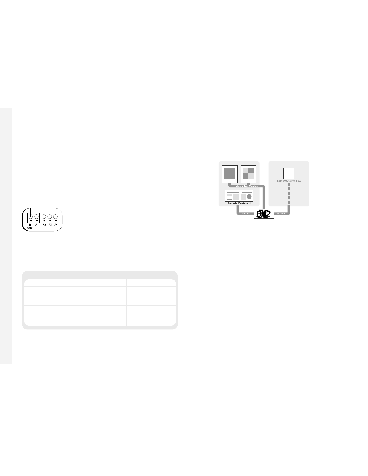
To add external `alarms:
• Connect the corresponding alarm contact to the alarm input, i.e. Alarm 2
would be connected between ground (GND) and A2.
• If multiple alarm modules are required then each will need to be addressed;
consult the alarm module documentation for details.
• Connect the 485-bus cable from the alarm box to one of the 485-bus sockets
on the BX2.
• The polarity of the alarms (normally open/closed) is set in the ‘Alarms and
Presets’ menu page.
Note: The alarm contacts do not have to correspond to the camera number, for
example alarm 2 could trigger camera 1, 2 and 3 into alarm mode.
An alarm trigger can be programmed to perform any of the following:
Action Menu page
Close/Open relay 1 Alarm Setup
Automatically copy the alarm camera to Zip® or Jaz® Alarm Setup
Display the alarm camera on screen (monitor A) Alarm Setup
Change the record rate Record Schedule
Record exclusively or interleave the alarm cameras Record Schedule
Sequence the alarms on the spot monitor Default Setting
Recall telemetry alarms presets Alarms Presets
An example of connecting a remote alarm box to the BX2:
Remote keyboards
A remote keyboard (DM/KBS3) can be connected to the BX2 to provide extra
functionality:
• Remote control from a distance of up to 1500m (4900ft).
• Control of multiple BX2 units.
• Control of on-board telemetry.
• Multiple keyboard control.
• Panic alarm button (record all cameras at the alarm rate and activate the
alarm relay, R1)
Page 16

13
The example below shows a remote keyboard connected of the BX2:
Video switchers
Video switchers allow multiple BX2s to be controlled from a single or pair of
monitors. This allows the flexibility of controlling up to 256 cameras from a single
location without having to purchase extra matrix equipment. The video switcher
routes the monitors from the BX2 being controlled to the operator’s monitors,
up to 16 control positions can have monitor switching.
The example below shows two BX2 units controlled from individual control
points. The video switcher routes the monitor outputs from the BX2 to the
control points:
Tip: Each 485-bus device is supplied with a 2m 485-bus cable. To extend the distance
between devices, two 485-bus junction boxes and 12v-power supply are required.
A total distance for the whole 485-bus network can be up to 1500m (4900ft).
Connecting Audio devices
BX2 can record and playback a single stream of audio linked to camera 1. There are
two audio input ports: MIC IN and LINE IN, and an audio output: LINE OUT.
Connecting a microphone to MIC IN.
Connect the microphone into the 3.5mm jack plug labelled MIC IN. It is important
to select the correct type of microphone for connection to the BX2. BX2 requires
an electret microphone with a sensitivity of –50dBV or better.
Connecting a pre-amplifier to LINE IN.
Where additional microphone gain and/or adjustable gain is required, an external
microphone pre-amplifier with adjustable gain is recommended. A microphone
pre-amplifier will provide a line level 1V pk-pk signal that can be connected to
the RCA socket labelled LINE IN on the BX2.
The line level input has the following specification:
Line IN 47kΩ input impedance, 1V pk-pk
Page 17

14
Connecting the LINE OUT to an amplifier.
Connect the RCA socket labelled LINE OUT to an external amplifier or powered
loudspeakers.
The line level output has the following specification:
Line OUT 1V pk-pk
Recording audio
Once the microphone or pre-amplifier is connected to the BX2, the option to
record audio should be enabled in the ‘System Options’ menu.
It is advised that you test the quality of audio playback, it may be necessary to
increase the gain of the microphone.
As the audio is linked to camera 1 recording, it is required that camera 1 be
viewed, either in a full screen or in a quad view during playback to hear the audio.
Using the menu
BX2 uses a paged menu system to guide the installer through the
installation process.
Entering the menu
There are two types of menus, User and Installer. The user menu will display only
the ‘Time, Date, and Language’ and ‘Schedule’ pages. The installer menu can
display all the menus.
To enter the Installer menu:
Press and hold the menu key.
To enter the User menu:
Ta p the menu key.
Navigating the menu
The menus are displayed with ‘options’ on the left-hand column and ‘settings’ in
the right hand column. A cursor (highlighted text) can be moved using the
cursor keys on the front panel, or the joystick on the remote keyboard.
Configuring
Time, Date & Language
Date 31/04/2002
Time W 12:00
Date format Day, Month
Language English
DST Auto
System Shutdown Disabled
Date
Cursor
Options Settings
Page 18

Time, Date & Language
Date 31/04/2002
Time W 12:30
Date format Day, Month
Language English
DST Auto
System Shutdown Disabled
15
To view the next page
Ta p the menu key to view the next page.
Tip: Tapping the
or keys will allow you to go back or forward a page in
the menus.
To exit the menu
Press and hold the menu key to exit the menus.
Tip: Cycling though all the menus by tapping the menu key will also exit
the menus.
Example of using the menu to change the time:
1. Press and hold the menu key to enter the installer menu. The ‘Time, Date &
Language’ page is displayed.
2. Use the cursor to select the ‘Time’ option on the left-hand side of the menu.
Time, Date & Language
Date 31/04/2002
Time W 12:00
Date format Day, Month
Language English
DST Auto
System Shutdown Disabled
Date
Time, Date & Language
Date 31/04/2002
Time W 12:00
Date format Day, Month
Language English
DST Auto
System Shutdown Disabled
Time
3. Use the cursor to highlight the minute settings
4. Use the cursors to change the settings, in this example 12:30.
5. Use the cursor to return to the left-hand side of the page and select another
option. Or, press and hold menu to exit the menu.
Time, Date & Language
Date 31/04/2002
Time W 12:00
Date format Day, Month
Language English
DST Auto
System Shutdown Disabled
00
Time, Date & Language
Date 31/04/2002
Time W 12:00
Date format Day, Month
Language English
DST Auto
System Shutdown Disabled
30
Time
Page 19

Time, Date & Language
16
Time, Date & Language Date 01/05/2002
Time S 12:00
Date Format Day, Month Month, Day
Language English Français, Deutsch, Espanól, Italiano
System Shutdown Disabled Enabled
DST Auto Manual
Date
As default, the date is entered DD:MM:YYYY on PAL models and MM:DD:YYYY
on NTSC models, this can be changed using the Date format option below.
Time
The time should be entered in 24 hour format (HH:MM).
Note: Summer and Winter time is signalled by an ‘S’ or ‘W’ next to the time.
Date format
The date format can be changed from Day, Month to Month, Day depending on
regional preference.
Language
The menus can be displayed in a number of languages. Upon selection these are
presented as a dropdown list.
Note: When the time and date is displayed as ‘External clock’ the time and date
settings are being taken from unit 1 on the 485-Bus network.
WARNING: Images may be overwritten if the time or date is adjusted whilst
recording is in progress.
System Shutdown
If the BX2 needs to be switched off for any reason, the shutdown procedure
needs to be followed:
1. Select ‘Enabled’ in the System Shutdown option.
2. When the pop-up menu appears, press and hold camera 1 for five seconds
to shutdown.
3. When the message ‘It is now safe to switch off your unit’ is displayed,
switch the BX2 off at the wall.
Warning: Data loss or disk failure may occur if a system shutdown is not
performed before removing power.
DST
Daylight saving time can be adjusted automatically or manually. By default, the
automatic setting will go forward one hour on the last Sunday in March at 01:00,
and one hour back last Sunday in October at 02:00. The default automatic
settings can be changed. If the country where the unit is located does not use
DST then select ‘Manual’.
Page 20

17
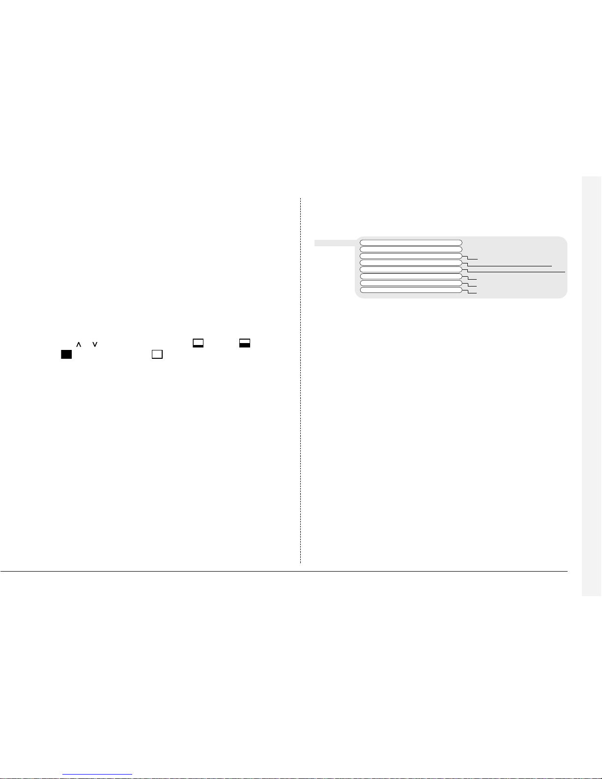
Camera Viewing
An option is available to view all cameras or selected cameras. All the cameras
are viewed by default. Cameras removed from viewing do not affect the cameras
being recorded.
To change the cameras to be viewed
• Press the ‘ ’ cursor key to change the edit field to ‘Selected cameras’.
• A menu will display the cameras to be viewed.
• Press the camera key to toggle the camera in or out of the viewed sequence.
This camera will be displayed. A filled box denotes cameras that can be viewed.
Note: Cameras removed from view are not displayed on the main or spot
monitor in live or playback mode, multiscreen displays will show a blank segment.
Tip: It is advisable to set an installer password to stop this setting being altered
by unauthorised personnel.
Schedule
A schedule can be used to record selected cameras at different times, change the
record rates, and select whether alarms or activity is enabled.
The schedules have three options:
• Off - the schedule is disabled
• Set/Unset - use a switch or alarm input to trigger the schedule. This is
connected to the DIRECT input, or by using a specific contact on the AUX
ALARM connecter or external alarm module.
• On between - the schedule is triggered between user defined times (and days
for the weekend schedule).
The schedule gives the option to switch to night and weekend settings, either
manually using the Set/Unset option or automatically at pre-set times and days.
Note: The Weekend setting overrides any night settings during the defined
weekend period.
Weekend Off
Set/Unset Direct
Module 01 contact 01
Aux contact 1-16
On between Friday 18:00
Monday 09:00
Night Off
Set/Unset Direct
Module 01 contact 01
Aux contact 1-16
On between 18:00 and 09:00
Page 21

18
Record Schedule
The record rate and image size determine the amount of time cameras can be
recorded for and the update rate of each camera. Settings can be applied to day,
night, and weekend schedules.
Standard PPS Event PPS Events active Event mode
Day 6 6 Both Interleave
Alarms Exclusive
Activity Unchanged
None
Night 6 6 None Interleave
Alarms Exclusive
Activity Unchanged
Both
Weekend 3 3 None Interleave
Alarms Exclusive
Activity Unchanged
Both
Recorded file size 18 KB
Max recording time --:-Total video storage 606GB
Earliest recording 01/05/2002 12:00
Earliest event 01/04/2002 12:00
Note: The Night and Weekend options are only displayed if a corresponding
Night and Weekend schedule has been configured in the Schedule menu.
Standard and Event PPS
Select a record rate in pictures per second (PPS) to be recorded across all cameras.
The camera recording priority can be adjusted in the advanced record schedule
page.
The default record rate is 6PPS, this is the equivalent to a VCR in 24-hour
time-lapse mode.
The table below shows the equivalent record rates of typical VCR time-lapse modes:
VCR Timelapse mode (hours) BX2 Record rate (PPS)
3 (2) 25 (30)
12 12
24 6
48 3
72 2
168 1
Figures in brackets are for NTSC systems.
Tip: To work out the update rate per camera – the number of seconds before
the camera is updated. Divide the number of cameras by the record rate (PPS).
For example, 16 cameras with a record rate of 6PPS will be:
Update rate (seconds) = Number of cameras = 16 = 2.67 seconds
PPS 6
You can decrease the update rate by increasing the record rate (PPS), the only
drawback is that the total recording time will decrease.
Page 22

19
Events active
Select whether the alarms and activity are on or off for day, night, and weekend
schedules.
Event mode
This option allows the record sequence to be adjusted when an event is received,
the options are:
Unchanged The record sequence remains the same whether an event
is present or not.
Exclusive Only event cameras are recorded.
Interleaved Event cameras are recorded more frequently than non-event
cameras, i.e. if camera 1 is in alarm the interleave recording
would be 1213141516…
Tip: By using event interleave, it is possible to keep the record rate constant but
effectively increase the speed of alarm or activity recording.
Recorded file size
The file or image size affects the quality of the images recorded to disk. A larger
file size has superior picture quality, but will fill the hard disk faster, so less time
will be recorded before the images are overwritten.
The file size can be set between 6 and 45KB. The table below shows the image
quality at typical file sizes:
Image quality File size (KB)
VHS 14KB
S-VHS 18KB
S-VHS+ 25KB
Note: The equivalent image quality is representative in most circumstances,
however, camera views with large amounts of image detail may require the file
size to be increased to obtain a similar image quality.
Increasing the file size over 40KB will decrease the maximum record rate.
Maximum recording time
The maximum recording time is the number of days and minutes before the
images are overwritten. The maximum record time is calculated automatically
when the standard or event record rate is highlighted and changed. Note that the
maximum recording time will include the audio, if it is enabled in the System
Options menu page.
Tip: Reducing the file size (KB) or record rate (PPS) can increase the maximum
recording time.
Page 23

20
Total video storage
The figure displayed shows the total amount of internal and external disk capacity
available for video storage in GB (Gigabytes).
Earliest recording
The earliest recording displays the date and time of the first image on the disk.
Note: If an event partition is set (in the System Options menu) then the earliest
recording could be an event that is older than the first standard recording.
Earliest events
This displays the time and date of the earliest event on the disk, this is only
displayed if an Event partition has been configured in the ‘Systems Options’ page.
Recording events only
BX2 can be configured to record cameras with activity or alarm events only, which
can increase the amount of time the hard disk can record for before being
overwritten.
To configure BX2 for event only recording:
1. Set the Standard PPS to 00.
2. Set the Event PPS to the desired record rate when an event is detected.
3. Select the ‘Events active’ option as either Both, Alarms, or Activity as required.
4. Select ‘Event mode’ option as Exclusive to record only cameras with alarms
or activity.
Only activity or alarm events will now be recorded. Note that pre-alarm/activity is
not possible in this configuration.
Cameras connected to the BX2 can be recorded at a High, Medium (Standard) or
Low priority for day, night, and weekend schedules. This allows cameras in
sensitive areas to be recorded more frequently than cameras located in less
sensitive areas.
By default, all connected cameras are set at the Standard record priority; cameras
that are not connected are greyed out and cannot be changed.
As the user changes the priority levels, the update rate per camera (in seconds) is
automatically calculated by the BX2 for High, Standard, and Low priority cameras
and also the Average update rate.
The update rate is based on the record rate (PPS) set in the Record Schedule
menu and the number of cameras connected to the BX2. The update rate per
camera is the number of seconds before the camera is updated when recorded,
for example, if the High priority setting is 2 seconds, then each camera set to
high priority would be recorded every 2 seconds.
Camera 1 2 3 4 5 6 7 8 9 10111213141516
Day
Night
Weekend
Low Standard High Not recording
Update Rates Av Low Standard High
per camera (secs) (secs) (secs) (secs)
Day 2.66 5.33 2.66 1.33
Night 2.66 5.33 2.66 1.33
Weekend 2.66 5.33 2.66 1.33
Advanced Record Schedule
Page 24
21
The recording priority can be adjusted for each camera for Day, Night, and
Weekend schedules. Note that changing the priority of a camera, or not
recording cameras will not increase or decrease the recording time, the Record
rate and the File size in the Record Schedule menu are used to set this.
Note: The Night and Weekend options are only displayed if a corresponding
Night and Weekend schedule has been configured in the Schedule menu.
To change the priority of cameras to be recorded:
1. Ensure that the correct record rates have been set in the ‘Record Schedule’ menu.
2. Move the cursor to a camera to be prioritised.
3. Tap either or to change the priority to Low , Standard , or
High priority or not recording .
4. Continue to select the priority of each camera, notice that the update rates are
automatically calculated depending on the number of cameras recording at
each rate.
5. If the update rate is not fast enough, you may need to reduce the number of
high priority cameras or increase the record rate in the Record Schedule menu
(although this will affect the recording time).
Note: The record priority is not used when activity detection or alarms are triggered.
Alarm SetUp Pre-alarm 00 min 00 sec
Post-alarm 00 min 02 sec
Auto copy No Yes
Global alarm contact Aux 17 Off, Direct, Module XX Contact XX
Alarm relay (R1) Close Open, Momentary open, Momentary close
Alarm display No Yes
Alarm buzzer No Yes
Camera fail buzzer No Yes
Pre-alarm
Pre-alarm images can be recorded for a pre-set time prior to an alarm. Select the
number of minutes or seconds (30 min 59 sec maximum).
Note: Pre-Alarm Recording only occurs if standard recording is taking place.
Post-alarm
Post-alarm images can be recorded for a pre-set time after an alarm has cleared.
Select the number of minutes or seconds (30 min 59 sec maximum).
Auto copy
Alarms can be automatically copied to an external Zip® or Jaz® disk.
Global alarm contact
A global alarm contact is used to force all cameras into an alarm condition.
This could be used if one alarm needs to trigger all cameras, or as a panic alarm
operated manually. Options are:
Aux Using the on-board auxiliary alarm inputs (default
contact 17).
Direct Using the DIRECT input on the rear of the unit.
Module XX Contact XX Using an exter nal remote alarm module (DM/CI01),
Module XX is the module number and Contact XX is
the contact number.
Off The global alarm is not used.
Alarm Setup
Page 25
22
Alarm display
By default, the last alarmed camera is not displayed on the main monitor.
Select ‘Yes’ to display cameras with alarms. The pre-alarm screen will be displayed
after the alarm has cleared.
Alarm relay (R1)
Choose whether the alarm relay (R1) will open or close when an alarm is
activated. Selecting Momentary open or Momentary close will open or close the
relay for a duration of half a second regardless of the alarm length.
Alarm buzzer
The buzzer built into the BX2 and the external keyboard can be triggered when
an alarm is activated by selecting ‘Yes’.
Camera fail buzzer
The buzzer built into the BX2 and the external keyboard can be triggered when a
camera fail is detected by selecting ‘Yes’.
Note: The camera fail buzzer will continue to activate until the failed camera is
reconnected or replaced. To deactivate the camera fail buzzer on the failed
camera, press and hold the corresponding camera key to enter the Camera Setup
menu and disconnect the camera video input.
Activity Setup
Activity SetUp Pre-activity 00 min 00 sec
Post-activity 00 min 02 sec
Auto copy No Yes
Extended Relay Off Aux, Module 01..16
Relay 2 (R2) Activity Close, Open,
Cam fail Momentary Close,
Both Momentary Open
None
Activity display No
Yes
Activity buzzer No Yes
Pre-activity
Pre-activity images can be recorded for a pre-set time prior to an activity event.
Select the number of minutes or seconds (30 min 59 sec maximum).
Note: Pre-Activity Recording only occurs if standard recording is taking place.
Post-activity
Post-activity images can be recorded for a pre-set time after an activity event has
cleared. Select the number of minutes or seconds (30 min 59 sec maximum).
Auto copy
Activity events can be automatically copied to an external Zip® or Jaz® disk.
Extended relay
This option allows activity detection to trigger an individual relay on the rear of
the unit or using an external relay module (DM/CI02/16). The relay connector on
the back of the unit and each alarm module has 16 relay outputs, corresponding
to the camera inputs. For example, when activity is detected on camera 1, relay 1
will close on the external relay module or on the rear of the unit.
Page 26

23
Relay 2 (R2)
Relay 2 (R2) on the rear of the unit can be configured to activate when activity
detection and/or camera fails are detected. Select whether the relay will close,
open, or momentarily close and open when activity is detected.
Activity display
By default, the last camera with activity detection is not displayed on the main
monitor. Select ‘Yes’ to display cameras with activity.
Activity buzzer
The buzzer built into the BX2, and the external keyboard can be triggered when
activity is detected by selecting ‘Yes’.
Display Options
Multiscreen interlace
Turn multiscreen interlace off if images are flickering when viewed in a
multiscreen display.
Multiscreen titles
Camera titles can be removed when viewing in a multiscreen display.
Display unit number
When multiple units are controlled from a single keyboard, the unit number
(in the System Options page) is displayed on screen so the operator knows
which unit they are controlling.
Base camera number
When using multiple units, it may be required that the camera numbers are
offset, for example, with two units the first unit would be camera 1 to 16
and the second 17 to 32.
Status page
A status page giving details of alarms and camera fails can be displayed when
entering the menus by switching this option on.
LCD contrast adjust
The contrast on the front panel LCD can be adjusted to suit the room lighting,
use the up and down cursor to increase or decrease the LCD contrast.
Display Options Multiscreen interlace On Off
Multiscreen titles On Off
Display unit number On Off
Base camera number 001 002…984
Status page On Off
LCD contrast adjust -----|-----
Page 27

24
Passwords
User password
The user password allows authorised users to enter the ‘Time, Date, and Language’
and ‘Schedule’ menu pages (all other menu pages are not displayed). To set the
password, select On and follow on-screen instructions. A user password can be
up to 8 digits long using camera keys 1 to 9.
Note: Tapping the menu key enters the User menu.
Installer password
The installer password allows authorised users to enter and view all the menu
pages. To set the password, select On and follow on-screen instructions.
An installer password can be up to 8 digits long camera keys 1 to 9.
Note: Pressing and holding the menu key enters the Installer menu.
Playback password
When the playback password is switched on, an installer or user password must
be entered before images can be played back.
WARNING: For security reasons, loss of passwords will require the unit to be
returned to Dedicated Micros for the passwords to be reset.
Make a note of your passwords here:
User password:.................................
Installer password:............................
Passwords User password Off On
Installer password Off On
Playback protection Off On
System Options
Unit number
When multiple units are connected together using the 485-bus a unit number
should be set for each unit. Unit 1 is also the master clock on the 485-bus
network, time and date settings will be synchronised to unit 1.
Network settings
This option is used to configure the unit for connection to an Ethernet network.
A pop-up box for configuring the network settings is displayed with the following
items:
System Options Unit number 01 02…16
Network settings Edit
Factory default Reset
IR receiver Enabled Disabled
Audio Disabled Enabled
Event partition Edit
Event copy destination None (Drive letter)
Image Storage Edit
Timed expiry Edit
Serial telemetry None (Dome manufacturer)
Network Settings
System name BX2
IP address 000.000.000.000
Subnet mask 255.255.000.000
Default gateway 000.000.000.000
1 – 100%
Disabled
Network Enabled
Bandwidth limit 100%
Page 28

25
System name
Each BX2 on the network can be given a system name to help identification, the
unit name is displayed in the Network Viewing software and also the LCD display
of the remote keyboard. The maximum number of characters for the system name
is 30. The default unit name is ‘DM BX2’.
Note: The unit name is not displayed across a WAN.
Tip: If you do not want the unit to automatically identify itself on a network, use
a ‘#’ symbol as the first character. You will still be able to access the unit across the
network by typing in the IP address directly into the Network Viewing software.
Network
This option is used to enable or disable the network option. The network is
enabled by default.
Bandwidth limit
The bandwidth used by the BX2 can be limited to prevent overloading
on slower networks. The BX2 has a 10MB/s connection (10Base-T).
The maximum bandwidth that a BX2 will use (5 users viewing images)
is 6Mb/s so any limiting over 60% does not affect the bandwidth used by the
BX2. The maximum bandwidth used by one user is approximately 2.5Mb/s
If you want to limit the bandwidth used by the BX2 to 1Mb/s set the bandwidth
limit to 10%.
Restricting the bandwidth does not decrease the image quality, but the update
rate of the images over the network will decrease.
IP address, Subnet mask, default gateway
A unique IP address and a subnet mask must be given to the BX2 in order to
communicate with it over a network. On an existing network these are often
obtained from the network administrator. A Default gateway will be required if
the BX2 is going to be operated from a remote location,
such as a WAN or dial-up via a router.
Note: The BX2 requires a Static IP address, even if it is connected to a dynamic
(DHCP) network.
Audio
A single channel of audio can be recorded on the BX2, use this menu to enable
or disable audio recording. Audio recording takes up a small amount of storage,
approximately 4KB/s, this is regardless of the record rate (PPS) of the video. When
audio is enabled the record time is affected, check the new record time in the
‘Record Schedule’ menu.
Note: The audio recording is linked to Camera input 1 recording, when playing
back the audio, camera 1 must be displayed.
IR Receiver
The Infrared remote control option can be enabled or disabled from this menu.
The remote control mimics the front panel control of the BX2. The remote control
does not allow the configuration of the menus or control of telemetry cameras.
When the IR receiver is enabled the IR LED on the BX2 is solid green, when it is
disabled the IR LED switches to solid amber. The LED flashing green signifies an
IR signal being received. Please refer to Appendix 2 for details of using the
remote control.
Page 29

26
Event partition
An event partition can be configured to protect events for longer than using just
the normal recording partition. When an event partition is configured, all events
will be saved to this area. The events are overwritten on a first in first out basis
when the partition is full.
To work out the required event partition size, use the following equation:
Where;
Days = Number of days required before the events are overwritten.
Image size (KB) = The recorded image size in kilobytes.
% Events = The percentage of recordings which are events.
Event PPS = The record rate of event recording (PPS).
For example, If you want to keep events for 5 days before they are overwritten,
alarms are triggered for 25% of the time, image size is 18KB, and the Event PPS
is 6 pictures per second the equation would be:
Caution: Specifying an event partition will reduce the disk space for normal
recording, reducing the recording time on disk.
Event partition (GB) = 5 x 18 x 25 x 6 = 12GB
1111
Event partition (GB) = Days x Image size (KB) x % Events x Event PPS
1111
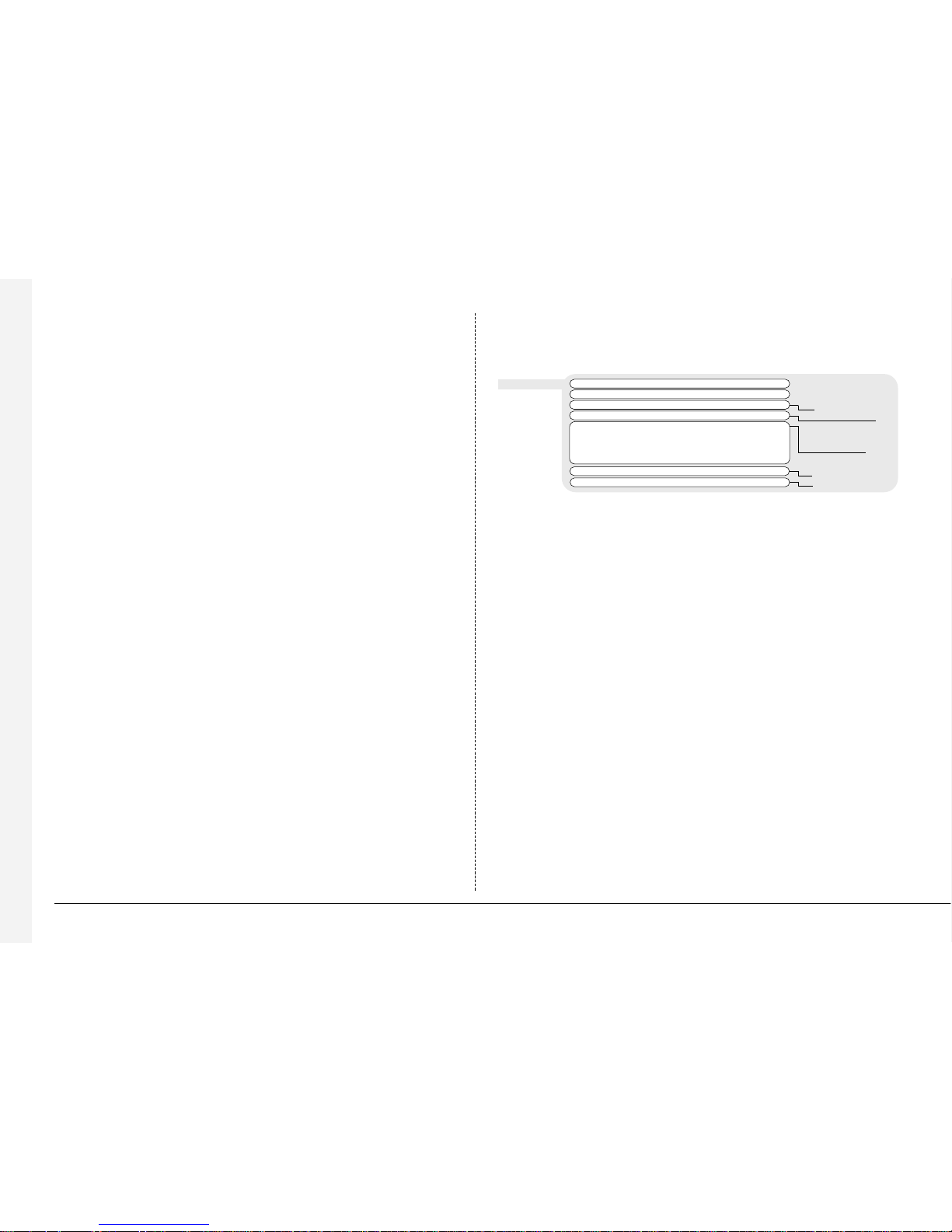
Image Storage
It is possible to select which drive(s) to record images to, for example, if you have a
RAID or disk array connected to the BX2 you can elect to record images to
the external storage only, giving greater image security.
Selecting Edit will bring up a pop-up menu with the following options:
The above example has an external RAID’s or disk array (drive L) connected to a
BX2 which will be recording images, the event log will be recorded to the C drive.
Timed expiry
Images recorded onto disk can be programmed to expire after a user-defined
number of days and hours. This option is useful if you are required to adhere to
legislation on maximum recording time, for example, 31 days.
Warning: Once the timed expiry has been set, all images older than the selected
time will be lost.
C D E F L
Image Storage ■ ■ ■ ■ ■
Event Log ■❏❏❏❏
Page 30

27
Serial telemetry
The BX2 has an RS-485/232 serial telemetry port on the rear of the unit. At the
time of writing this port supports the following domes:
Select the type of telemetry from the list to configure the Serial telemetry port.
Each dome will need to be configured for serial telemetry and addressed correctly.
Refer to the dome manufacturers documentation for details, alternatively a
supplementary document for using domes on BX2 digital recorders is available for
download from our website or by request from our Technical Support department
at support@dmicros.com
Note: Once the Serial telemetry is selected, the telemetry type for each camera
must also be selected in the ‘Alarms and Presets’ menu page. Only one type of
serial telemetry is permitted per machine.
Ultrak Ultradome™ KD6
Ademco / VCL Orbiter and Jupiter Microsphere™
JVC TK-C675, TK-C553E
Dennard 2050
Panasonic WV-CS850, WV-CS854
Aritech / Kalatel CyberDome™
Sensormatic Speeddome™ V
Pelco P Spectra II, Spectra III
Title
Each camera title can be up to 12 characters long.
Input termination
The input termination does not auto detect by default, the termination must be
set manually On (default) or Off. The termination must be set to Off if the camera
is looped through to other equipment.
Camera type
Cameras are detected automatically, to change the camera type choose colour
or mono.
Alarm input/Polarity
Select whether the alarm connected is Normally open (default), Normally closed,
or Off.
Colour adjust
When the colour bar is selected, press to reduce, and to increase the colour.
Note: this option is not displayed if the camera is set as monochrome.
Contrast adjust
When the contrast bar is selected, press down to reduce, and up to increase
the contrast.
Camera video input
This option is only displayed when a camera has failed or is offline. Select
disconnect whilst the camera is offline to prevent the camera fail message and
alarm being triggered.
Tip: This menu can be entered directly by pressing and holding a camera key.
Camera Setup
Camera Set-Up Title CAMERA 1
Input termination On Off
Camera type Auto detect Colour, Mono
Alarm input/Polarity Normally open Normally closed, Off
Colour adjust
Contrast adjust
Camera video input Connected Disconnected
Page 31

28
Alarms and Presets
Alarms and Presets Camera XX Detected Not Detected
Telemetry protocol None BBV, Pelco, DM, (serial telemetry)
Preset Mod/Aux Contact Input
> -- Aux 01 N/O
>----
Camera XX
The currently selected camera number is displayed, along with its status detected or not detected. Press a camera key to select a camera to configure
alarms and presets for that camera.
Telemetry protocol
Select the telemetry protocol for the camera; BBV, Pelco, DM, or the serial
telemetry dome selected in the ‘System Options’ menu page.
BBV and Pelco is Coaxial telemetry, if you are using Pelco serial telemetry it is
displayed as ‘Pelco-P’. DM telemetry is twisted pair DTMF telemetry (using a
TAD3) or 485-Bus telemetry.
Note: Tours are not available when using Pelco coaxial telemetry.
Notes for JVC domes: There are two types of serial telemetry for JVC domes:
type 1 and type 2. Select the correct type to correspond to the model number
from the list below:
Type 1 Type 2
TK-C675E TK-C675BE
TK-C675U TK-C675BU
TK-C553E
Preset
If the camera has telemetry presets configured, these can be recalled when
an alarm is triggered. Enter the preset number from 00 to 99 for the selected
alarm contact.
Mod/Aux
Alarm contacts can be connected to the auxiliary alarms on the rear of the unit,
or using an external alarm module. If an alarm module is to be used, select the
address of the module being used, 1 to 16. Up to 16 alarm modules can be
connected to the 485-bus network.
Contact
Each alarm module has 16 alarm inputs, each input can be used by any camera
or multiple cameras.
Input
Select whether the alarm contact on the alarm device is normally open (N/O)
or normally closed (N/C).
Page 32

29
Activity Camera Setup
Activity detection is used to record more images to disk from cameras that have
activity. The sensitivity of activity can be adjusted and areas can be masked off
according to the scene type.
Detection
Select whether activity detection is on or off for the selected camera.
Sensitivity
There are 5 levels of sensitivity for activity detection.
Select the sensitivity level which matches the camera’s placing. Cameras sited
outdoors where there may be a lot of background movement, such as trees or
rain, should be set to Outdoor high or Outdoor low sensitivity. Cameras sited
indoors where there is very little background movement should be set to Indoor
high, Indoor low, or very low sensitivity.
Activity grid
An 8 x 16 grid is used to mask areas where activity detection is enabled. When
the grid is displayed, use the cursor keys to move the cursor to the desired
location and press a camera key to toggle the block on (white dot) or off.
Activity Camera Set-Up Detection Off On
Sensitivity Outdoor high
Outdoor low, very low, Indoor high, Indoor low
Activity grid Setup
Activity test Walk test
Activity test
Use this option to test and tune the sensitivity and activity grid set up for each
camera. When activity is detected on the camera a white dot is displayed. Press
the mode or menu key to exit the test.
Activity detection can perform the following:
Action Menu page
Close / Open relay 2 Activity Setup
Automatically copy the activity to Zip® or Jaz® Activity Setup
Display the activity camera on screen Activity Setup
Change the record rate Record Schedule
Record exclusively or interleave the activity cameras Record Schedule
Close individual relays Activity Setup
Page 33

30
Operating
Viewing single cameras
Full
Pressing a camera key will display a full screen image of that camera.
Zooming an image
Press the same camera key to toggle zoom on and off.
When zoom is enabled, use to scroll around the image.
Freezing an image
Double tap the camera key or press the Hold key on the remote keyboard
to toggle freeze frame on or off.
Viewing multiple cameras
Picture in Picture
Press the PIP key to toggle the main and PIP image.
Press and hold the PIP key to edit the display, use to select the
segment, press the required camera key to fill that segment.
Press menu to exit.
Quad
Press the QUAD key to switch to quad display.
Press and hold the QUAD key to edit the display, use to select
the segment, press the required camera key to fill that segment.
Press menu to exit.
Multi-screen
Press the multi-screen key to toggle between 9-way, 8+2, 12+1, and
16-way displays.
Press and hold the Multiscreen key to edit the display, use
to select the segment, press the required camera key to fill that segment.
Press menu to exit.
Sequencing cameras
Sequence
Press the sequence key to toggle the main monitor sequence on or off.
Press and hold the sequence key to edit the full screen sequence.
Use the camera keys to include or remove cameras from the sequence.
Press menu to exit.
Note: The spot monitor sequence can only be activated or edited in spot mode.
Viewing cameras on the Spot monitor
Press the mode key or spot key on the remote keyboard to toggle ‘spot’ mode,
indicated on the main monitor and the front panel LED.
Press a camera key to display that camera on the spot monitor or tap the
sequence key to sequence the cameras.
Press and hold the sequence key to edit the spot sequence. Press menu to exit.
Using the Event log
Alarms and activity detection are tagged and stored in the event log for easy
retrieval. Each event is labelled with event type (alarm or activity), its camera title,
time, and date. To view an event from the event log:
• Tap Event to display the event log.
• Use and to select the event required, the selected event is displayed in
the preview window.
• Tap to view the event in full screen.
▲
Page 34

31
Filtering the Event log
The event log can be filtered by time and date, type of alarm, event state, or by
camera. To filter the event log:
• Press and hold event to display the event filter menu.
• Use to move the cursor.
• Use to toggle the box on n or off o, or change the time or date.
• Press event to see filtered event log.
Tip: It is advisable to filter the events before displaying them when recording over
a number of days.
Event type
Select whether Alarms, Activity detection or Systems alarms (panic alarms,
time/date change, power up/down) are displayed.
Event state
Select whether the event is to be displayed when it is triggered (On) or when it
ends (Off) or both.
Note: Cameras cannot be selected using the cursor keys.
Alarm Activity System
Event type
■■ ■
On Off Both
Event state
❏❏ ■
Filter from 00:00 01:01:1999
Filter to 12:00 01:01:2000
Time now
123456789
■■■❏❏❏❏❏❏
Camera Select
Activity Search
Camera 4
Copy destination CDR list/External
Activity grid Setup
Activity from Time/Date
Activity to Time/Date
Playback time
Press << to begin search
Filter from
Select the time and date of the first event to be displayed. If there is no event at
the selected time, the next nearest event is displayed.
Filter to
Select the time and date of the last event to be displayed. If there is no event at
the selected time, the next nearest event is displayed.
Time now
Moving the cursor onto the ‘time now’ text changes the ‘Filter to’ option to the
current time and date.
Camera select
Use the camera keys to toggle whether the camera events will be displayed or
not. In the example above only cameras 1 to 3 will be displayed in the event log.
Using Activity Search
It is possible to search an area of the screen for activity or movement at specified times.
To search and area of the screen for activity:
1. Enter playback mode by tapping either
or , or pressing and holding the
GOTO key.
2. Press and hold the ‘Event’ key to display the Activity Search menu:
Page 35

32
Camera number This is the camera number you will be performing the search
on, press a camera key to change to the relevant camera number.
Copy destination This is the device you wish to copy selected images to, (select
External to copy to Zip/Jaz, or CDR List to copy to the CDR Archive page)
Activity grid Use the Activity grid to highlight an area of the screen you wish to
search for activity.
Activity from Enter the time and date you wish to search from. The default is
the earliest recorded time on the disk.
Activity to Enter the time and date you wish to search to.
Playback time Select this option to automatically enter the last playback time
and date the user was viewing into the ‘Activity to’ option.
3. Once the Activity Search screen has been completed, press
to begin the
search, the following screen is displayed:
Please Wait
Reading Disk
18 Found
Press ‘Event’ to cancel search
Activity Search
Camera 4 10:01:43 25/6/2002
09:52:02 25/6/2002
09:30:00 25/6/2002
11:20:20 24/6/2002
===============
Activity Image
The BX2 will search the hard disk for
activity in the selected areas. Once it
has found 20 (for PAL units) or 18 (for
NTSC cameras) events the activity list
will appear. The Activity search can be
cancelled at any time by tapping
the ‘Event’ key; any events found up
to that point will displayed in the
activity list. A typical example of an
Activity List would be:
Use keys to move the highlight up and down the list, the Activity image is
automatically updated as the highlight moves. From this screen you can perform
the following:
Play an activity back in full screen
Highlight the required activity event and press to play it back in full screen.
Tap the ‘Event’ key to return to the Activity list.
Copy an event to CDR or external Zip and Jaz
Highlight the event to be copied, and press the copy button. The event will be
copied to the CDR Archive list. If the ‘Copy destination on the previous page is
set to ‘External’, then the images will be copied to an external Zip or Jaz disk.
View more activities
To view more than a page of activities scroll down to the bottom of the list,
the unit will search further back in time and another list of activities will appear.
When there are no more activities to list an end bar ‘===============’
is displayed.
Start a new search
If you wish to start a new search, you must tap the ‘menu’ key to exit the
Activity list, then re-enter ‘Activity search’ as described in step 1.
▲
Page 36

33
Copying images to CD
To copy images to the internal CD writer:
1. Insert a blank CDR or pre-formatted CD-RW into the CD writer.
2. Press and hold the copy key to display the following screen:
Copy Images
Copy destination CD0: SCSI Yamaha
Copy from time 12:01:00 01/12/2001
Copy to time 12:02:00 01/12/2001
Copy Selected cameras
1 2 3 4 5 6 7 8
■ ■ ■ ■ ❏ ❏ ❏ ❏
9 10 11 12 13 14 15 16
❏❏ ❏❏ ❏❏❏❏
Selected cameras
Copy destination This is the name and type of the internal or external CD drive.
Copy from time Select the time you wish to copy images from.
Copy to time Select the time you wish to copy images to.
Copy Select ‘All cameras’ or individual cameras to copy using the camera keys
(filled boxes are selected cameras, unfilled boxes are not selected).
CDR Archive
CD Type – 656MB CD
CD Use [--+---------------] 4% Full
From To Cameras
12:00 01/12/01 12:01 01/12/01 123456789
Next 12:01 01/12/01 to 12:02 01/12/01
Add next Create CD Verify CD Clear list
Add next
3. Use the cursor keys to change the
time to copy ‘to and from’.
4. Tap the menu key to display the
following menu:
This menu displays the archive list of images to be copied to the CD, the ‘CD Use’
bar indicates the how much space is available on the CD, once it reaches 100%
no more images can be added to the archive.
Add next Add the selected times to the archive list.
Create CD Creates a CD with the images in the list.
Verify CD Verify that the CD has been written correctly.
Clear list Removes all entries from the list.
To select any of the above options, highlight the option and tap menu.
To add images to the CD:
1. Select ‘Add next’ and press the menu key to add the displayed time to the list.
2. You may wish to add more images to the CDR archive if the CD is not yet full.
To select more images to add to the list press
to return to the ‘Copy
images’ screen.
3. Once all the required images are added to the archive list, select ‘Create CD’
and press the menu key to create the CD.
4. The CD can be verified if required using the ‘Verify CD’ option.
5. Press and hold the menu key to exit the CDR Archive option.
Page 37

34
Appendix 1
Configuring for tape archive
To configure the BX2 for tape archive:
1. Enter the Tape Menu
Press and hold
II
(pause) on the BX2 to display the tape menu:
Note: When Eject Tape and Tape Status options are ‘greyed out’, no tape is inserted.
2. Select the Tape length
The correct tape length needs to be set to allow BX2 to calculate the amount of
images on a tape. To select the tape length:
1. Use the cursor keys to move the cursor to Tape Length.
2. Press the cursor key to highlight the tape capacity.
3. Use the cursor keys to adjust the tape capacity* in Gigabytes (GB)
* Ensure the uncompressed capacity of the tape is entered, not the compressed capacity, e.g. some
DDS-3 tapes are labelled as 24GB, but the actual uncompressed capacity is 12GB.
Tape Menu
> Eject Tape
> Tape Length 12 GB
> Eject Schedule
> Tape Status
> Write Overwrite
>
3. Configure an Eject Schedule (optional)
If no Eject Schedule is configured, then by default, BX2 will eject each tape when
it is full. An Eject Schedule will eject the tape at a specific time of the day
whether it is full or not. This is useful if the tape needs to be changed at a set
time each day, or if more than one tape is to be used in a day.
To configure an Eject Schedule:
1. Move the cursor to Eject Schedule using the keys.
2. Press the cursor key to display the eject schedule in a new window.
3. Use the keys to move to the required day, and the keys to highlight
the required field.
4. Use the keys to change the eject time in each field, up to 4 eject times
can be set for each day.
5. Press mode/menu to exit the Eject Schedule page.
Page 38

35
Selecting Tape Status at any time will display the status of the tape currently in
the drive:
The tape status indicates:
• The tape ID and percentage of tape full.
• When the tape was first and last used, and the Machine ID which was used.
• The number of times the tape has been used.
• The number of archive sessions on the tape. A session is added when the tape
is appended to rather than overwritten.
• The session number.
• The first and last image recorded in the selected session (use the
keys to
change the session number).
The Write Overwrite/Append option gives a default setting if a tape is inserted
and a ‘Write to tape method’ is not chosen after a 5 minute timeout. This feature
is not yet implemented.
Select Eject Tape if you wish to eject the tape at any time during archiving. The
tape will finish writing the block of images it is currently archiving before ejecting
the tape, which may take up to 5 minutes.
Tape ID 717557F8 Tape is 82% full
First Written 28/02/2000 DVT33R01-00000081
Last Written 28/02/2000 DVT33R01-00000081
Tape has been used 001 times
Tape contains 02 Archive Sessions
Session 1 IMAGES/MONDAY/TAPE 5/SESSION A
First Image 17:12 27/02/2000
Last Image 17:20 27/02/2000
To change session use
keys
WARNING: Do not use the eject button on the front of the tape drive to eject
tapes, as this will cause data to be lost.
Archiving to tape
The difference between archiving on a VCR and archiving on a tape drive is that
the VCR is archiving images constantly, whereas the tape is archiving images
periodically from the internal disk.
The advantages of archiving periodically is that unlike videotape, a tape can be full
(or even ejected) and images will still be recorded to the internal disk, therefore
images are still recorded when changing tapes. There is also less mechanical wear
on the tape drive, as it is not recording all the time.
To archive images to tape:
1. Insert a tape into the tape drive.
2. The tape status box is displayed, showing the contents of the tape, along with
the following menu:
Note: It is normal for a few minutes to elapse before the above menu is displayed
as the tape needs to rewind and read the index.
> Background archive
> Selective archive
> Playback
> Load files
> Eject Tape
>
Page 39

36
3. If the tape inserted is not the correct tape, or if there is information on the
tape you wish to keep, select Eject Tape and insert another tape.
4. Select Background archive. The option to Append (add images to the end of
the tape) or Overwrite the tape are given:
Caution: All previously archived images on the tape will be lost if the ‘Overwrite’
option is selected.
5. Use the keys to highlight the required option and press mode/menu
to continue.
6. The tape will now start the archive process.
Playing back archived images
PC Playback software is used to playback images from Zip®, Jaz®, and tape
drives from a PC.
System Requirements:
• Intel Pentium PC or equivalent (min. 233MHz, 400MHz recommended)
• Microsoft
®
Windows®95 or 98.
• 4MB Video card capable of 16 million colours.
• 5MB Free hard disk space (additional space required for holding image files)
• Iomega Zip
®
, Jaz®, or tape drive connected to the PC.
• SCSI interface card (for connecting tape drives to the PC)
Write to tape method
Append or overwrite
Append
Installation:
1. Insert the disk into drive A.
2. Select Start > Run…
3. Type ‘a:\setup’ and click OK, alternatively use the Browse button to find the
file manually.
4. Installation will start, follow the on screen instructions.
Running the PC Playback software:
1. Select Start > Programs > PC Playback.
2. Click on the PC Playback icon.
3. PC Playback will load, click on the ‘Help’ option for operating instructions.
Important notes when using tape drives:
The cable supplied with the DDS drive may not be compatible with BX2
50-pin SCSI port.
DDS-3: A High-density 50-way male to Centronics 50-way male cable is required.
DDS-4: A High-density 50-way male to High-density 68-way male (DDS-4) is
required. This cable is available from computer suppliers.
Caution: Tape drives need frequent head cleaning to maintain optimum
performance, ensure the drive is cleaned to the manufacturer’s recommendations.
Page 40

37
Appendix 2
Using the remote control
The remote control included with the BX2 operates like the front panel, see the
operator card for details.
To use the remote control the ‘IR receiver’ option need to enabled in the ‘System
Options’ menu page.
1 2 3 4
5 6 7 8
9 10
UNIT
SELECT
MODE
HOLD SPOT EVENT GOTO
11 12
13 14 15 16
Note: If multiple BX2s are in the same location it is necessary to disable the ‘IR
receiver’ option in the system options menu on all but one of the units.
The remote control provides the following functions:
UNIT SELECT Press ‘UNIT SELECT’ followed by a
camera key to log onto another unit.
Note: The remote contol does not have the ability to
control a DM video switcher.
MODE Press to toggle Spot mode on and off,
or to return to Live mode when
playing back.
HOLD Toggle freeze frame On and Off.
SPOT Toggle Spot mode on and off, Selects
operation of the spot monitor.
EVENT Press to display the Event log.
GOTO Press to display the Goto time option.
1 - 16 Camera selection keys.
Use to control the cursor in menus,
or scroll around the screen when in
zoom mode.
Warranty information
Please check with your local Dedicated Micros office (or www.dedicatedmicros.com)
for warranty periods.
Please note:
• Warranty period commences from the date of DM invoice to the customer.
• Warranty excludes general wear and tear.
• Warranty is invalidated if the warranty label is removed or damaged, (i.e. if the
product has been opened or tampered with).
• Warranty repairs are conducted free of charge unless the equipment has been
tampered with or accidentally damaged (or exposed to power surge, etc).
• Dedicated Micros do not issue service replacements while goods are in repair.
If you have any questions regarding the warranty of your DM product, please
contact your local office for further information.
Page 41

38
Notes
Page 42

FRANÇAIS
1
Introduction
Contenu
• Précautions Importantes 3
• Installation du BX2 4
• Installation rapide 6
• Connexion des dispositifs externes 7
- Connexions à l’arrière du BX2 7
- Connexion des caméras télémétriques 7
- Connexion des dispositifs extérieurs de stockage 8
- Connexion á un réseau Ethernet 10
- Connexion des dispositifs de type 485-bus 11
- Connexion des dispositifs audio 13
- Enregistrement audio 14
• Configuration du BX2 14
- Utilisation du Menu 14
- Heure, Date et Langue 16
- Visualisation de Caméra 17
- Programmation Horaire 17
- Programmation horaire d’enregistrement 18
- Programmation Horaire Avancée 20
- Paramétrage d’alarme 21
- Paramétrage d’activité 22
- Options d’affichage 23
- Mots de passe 24
- Options système 24
- Paramétrage caméra 27
- Alarmes et préréglages 28
- Paramétrage activité caméra 29
• Fonctionnement du BX2 30
- Visualisation des images issues d'une caméra spécifique,
Visualisation d’un ensemble de caméras, Séquencement
des caméras, utilisation des mémoire d’événements 30
- Filtrage de la mémoire d’événements, 31
utilisation de la recherche d’activité
- Copier les images sur un CD 33
• Annexe 1 - Configuration pour l’archivage sur cartouche 34
• Annexe 2 - Utilisation de la télécommande 37
Le BX2 en quelques mots
Le BX2 est un ensemble très facile et d'un excellent rapport qualité/prix à utiliser
comprenant un multiplexeur vidéo efficient, un enregistreur vidéo numérique, un
enregistreur audio à un seul canal et un transmetteur vidéo en réseau.
Le multiplexeur vidéo :
• Conçu en pensant de la sécurité
• Simple d’utilisation
• Fonctionnement semblable à celui d'un multiplexeur analogique traditionnel,
non à celui d'un ordinateur
• Possédant toutes les fonctionnalités attendues de la part d'un multiplexeur de
Dedicated Micros :
- Moniteur principal et moniteur d'observation (‘spot’)
- Affichages multi écrans
- Détection d'activité
- Alarmes
- Programmation horaire pour jour, nuit et week-end
- Vitesses d'enregistrement variables
- Connexion réseau via un 485-bus
L'enregistreur vidéo numérique
• Possibilité de lecture et d'enregistrement simultané, sans conséquence néfaste
sur l'enregistrement
• Possibilité d'enregistrement non-stop jusqu'à 2 mois en mode ‘time-lapse’
• Accès instantané aux images enregistrées sur le disque dur sans avoir besoin
de cassettes
Enregistreur audio mono-canal:
• Enregistrement d’un seul canal de flux audio une fois avec les images
La transmission réseau :
• Possibilité de visualisation en temps réel et de lecture d'images provenant du réseau
• Aucun logiciel supplémentaire nécessaire. Le logiciel de visualisation en réseau
pour Windows™ est fourni.
• Possibilité de copier les images encodées dans le réseau
Page 43

2
FRANÇAIS
Caractéristiques :
Installation
Détection automatique de la présence des caméras lors ✔
de la mise sous tension
Détection automatique de la présence de dispositifs ✔
d'archivage lors de la mise sous tension.
Enregistrement de 24 heures en qualité S-VHS par défaut ✔
Raccordements en boucle ✔
Fonctionnement
Lecture, enregistrement, archivage et transmission simultanés ✔
Option de caméra cachée ✔
Contrôle via télécommande IR ✔
Lecture
Fonctionnement comparable à celui d'un magnétoscope traditionnel ✔
Modes de relecture ‘plein écran’, ‘quadravision’ et ‘PIP’ ✔
(image dans l'image)
Recherche activité ✔
Fonction GOTO (passer à) ✔
Evénements
Détection d'activité ✔
Alarmes ✔
Mémoire d'événements (avec fenêtre de prévisualisation) . ✔
Copie automatique des événements sur supports Zip® et Jaz®* ✔
Chronologie avant et après événement ✔
Télémétrie
Liaison coaxiale - BBV, Dennard, Pelco ✔
Liaison série - Ultrak, Ademco/VCL, JVC, Dennard, Panasonic,
Aritech/Kalatel, Sensormatic, Pelco-P ✔
DTMF/485-bus - DM ✔
Paramétrages prédéfinis de la télémétrie lors d'une alarme ✔
Audio
Enregistrement audio à canal unique en temps réel ✔
Commande clavier à distance (en option)
Compatibilité avec clavier distant ✔
Commande de plusieurs unités ✔
Commande de télémétrie ✔
Visualisation réseau
Visualisation en temps réel ✔
Visualisation en lecture ✔
Réseau de jusqu’à 5 utilisateurs simultanés ✔
Commande de télémétrie ✔
Possibilité de copier les images encodées dans le réseau ✔
Email notification lors de certains événements ✔
External storage devices
Zip® et Jaz® ✔
RAID ✔
Hewlett Packard DDS* ✔
Yamaha/Plextor CDR (vérifiez la compatibilité des modèles)* ✔
Internal storage devices
CDR ✔
* Vérifiez la compatibilité des modèles et leur disponibilité dans votre région
Page 44

FRANÇAIS
3
Précautions Importantes
Lire Les Instructions
Lisez avec attention toutes les instructions de sécurité et d'exploitation
avant de faire fonctionner l'unité.
Sources d’Alimentation
Faites fonctionner cette unité uniquement à partir du type de source
d'alimentation indiqué sur l'étiquette du fabricant.
Réparation
N'essayez pas de réparer cette unité vous-mêmes, car l'ouverture ou le
retrait du boîtier peut vous exposer à des tensions dangereuses ou à
d'autres risques. Seul un réparateur qualifié doit effectuer des
interventions sur cette unité.
Ventilation
Assurez-vous que l'unité est bien ventilée afin de la protéger contre les
surchauffes.
ATTENTION
Afin d'éviter tout danger d'incendie ou de décharge électrique, n'exposez pas
cette unité à la pluie ni à l'humidité. L'éclair fléché dans un triangle équilatéral
prévient l'utilisateur de cet équipement des tensions dangereuses à l'intérieur du
boîtier et indique que ces tensions sont telles qu'elles constituent un danger de
décharge électrique
Ce produit appartient à la classe A. Dans un environnement domestique, ce
produit pourrait causer une interférence radio qui obligerait l’utilisateur de
prendre les mesures nécessaires
REMARQUES REGLEMENTAIRES, INFORMATIONS FCC ET DOC
(Modèles américains et canadiens uniquement)
ATTENTION: Cet équipement a été testé et s'avère conforme aux limites d'un
équipement numérique de classe A, conformément à la partie 15 des règles FCC.
Ces limites sont conçues afin de fournir une protection raisonnable contre les
interférences nocives lorsque l'équipement fonctionne dans un environnement
commercial. Cet équipement génère, utilise et peut irradier des fréquences radio.
Si elle n'est pas montée et utilisée conformément au manuel d'instructions, cette
unité peut brouiller les communications radio. L'exploitation de cet équipement
dans une zone résidentielle est susceptible d'entraîner des interférences
préjudiciables. Dans ce cas, l'utilisateur sera tenu de corriger les interférences
àses propres frais.
Si nécessaire, l’utilisateur devrait consulter le vendeur ou un radio/television
spécialiste afin de remédier les défauts. L’utilisateur pourrait trouver utile le livret
suivant préparé par la Commission Fédérale de Communications : «Comment
identifier et résoudre les problèmes liés à l’interférence radio - télévision». Ce
livret est disponible par l’intermédiaire du Bureau Editeur des Etats Unis,
Washington, DC20402, numéro du stock
004-000-00345-4. Ce rappel a pour objet d'attirer l'attention de l'installateur
de systèmes de télédistribution sur l'Article 820-40 du NEC qui fournit les lignes
directrices de mise à la masse et qui spécifie précisément que le câble de mise
à la masse doit être relié au système de mise à la masse de l'immeuble le plus
près possible du point d'entrée du câble.
Marquage CE
Ce produit est marqué du symbole CE et indique sa conformité
à la directive 89/336/EEC sur la CEM de l'Union Européenne. Une
‘Déclaration de conformité’ se trouve chez Dedicated Micros Ltd.,
11 Oak Street, Swinton, Manchester M27 4FL, GB.
ATTENTION
Page 45

FRANÇAIS
4
Installation du
Avant de commencer :
Bien vérifier le contenu de l'emballage
❑
BX2
❑
Quatre supports de disque dur
❑
Combiné IR à distance
❑
Câble secteur avec prise trois plots (Amérique du Nord)
❑
Câble secteur sans prise (autres secteurs géographiques)
❑
Kit d'installation en rack (faces latérales, supports arrière et vis de fixation)
❑
Cable type 485-bus
Sélectionner un emplacement pour l'installation
Le BX2 est conçu pour être monté en rack ou sur table. Lors de son installation,
il est important de respecter les précautions suivantes :
• Les ouvertures présentes sur le boîtier de l'unité sont destinées à assurer sa
ventilation. Afin d'éviter tout risque de surchauffe, ces ouvertures ne doivent
en aucun cas être recouvertes ou obstruées.
• Si les unités doivent être empilées, il faut s'assurer qu'un espace d'au moins
1.5 cm reste libre entre chaque unité.
• S'assurer qu'un espace d'au moins 3 cm reste libre de chaque côté de l'unité.
• Vérifier que l'unité ne se trouve pas dans une zone où elle est susceptible de
subir des chocs de type mécanique.
• Il est préférable que l'unité soit placée dans un endroit peu humide et
quasiment sans poussière. Eviter par conséquent les lieux humides ou
poussiéreux, tels que les sous-sols ou les halls.
• En cas d'utilisation de support de stockage externe, se reporter aux
instructions du fabricant pour le placement du matériel.
• BX2 ne doit pas être installé dans un emplacement dont la température
dépasse 40°C
Aperçu rapide de la notion d'enregistrement numérique
Un enregistreur multiplex numérique fonctionne exactement de la même manière
qu'un multiplexeur analogique, mis à part que la vidéo est stockée sur des disques
durs et des cartouches numériques, à la place des cassettes vidéo. L'enregistrement
de type analogique utilise le mode ‘time-lapse’, afin d'étendre la durée enregistrable
sur une cassette de 2 ou 3 heures - c'est-à-dire en enregistrant moins d'images à la
seconde. Cette méthode permet également d'accroître la durée enregistrée sur le
disque dur du BX2. Cependant, avec un enregistreur multiplex numérique, il existe
d'autres facteurs permettant de modifier cette durée :
• La qualité des images
• La vitesse d'enregistrement
• La capacité du disque dur
Qualité d'image
Un enregistreur multiplex numérique stocke les images sous une forme
compressée, permettant ainsi d'améliorer l'efficacité de l'enregistrement. Plus
la compression est importante, plus la taille du fichier est réduite, mais la qualité
de l'image est évidemment moindre. Avec le BX2, la compression des images
peut varier entre 6 et 45 ko. Les capacités de stockage sont exprimées en
kilooctets et en gigaoctets :
1 Go = 1024 mégaoctets (Mo)
1 Mo = 1024 kilooctets (Ko)
Avec l'enregistrement analogique, la qualité de l'image dépend du type de
cassette vidéo utilisé, VHS ou S-VHS. Avec le BX2, la qualité varie selon la taille
d'image sélectionnée : par exemple, la qualité VHS correspond à 14 ko, SVHS à
18 ko et une qualité supérieure au S-VHS équivaut à 25 ko*. Le fait d'utiliser une
taille d'image plus importante a pour conséquence de remplir le disque dur plus
rapidement, étant donné que chaque image occupe plus d'espace. Pour pouvoir,
dans ce cas, conserver la même durée d'enregistrement, il est nécessaire de
réduire la vitesse d'enregistrement (ips).
* Remarquez que dans le cas de tous les enregistrements numériques, la qualité de l’image peut varier
en fonction du type de la scène, la qualité S-VHS peut avoir 14ko dans une scène mais elle peut aussi
avoir 30ko ou plus afin d’obtenir la même qualité dans une scène qui contient plusieurs détails.
Page 46

FRANÇAIS
5
Vitesse d'enregistrement
Cette vitesse correspond au nombre d'images enregistrées sur le disque en une
seconde (ou images par seconde : ips). Ce chiffre est un paramètre système, si
bien qu'il reste identique quel que soit le nombre de caméras (de 1 à 16) qui
enregistrent. Le taux de rafraîchissement propre à chaque caméra varie selon la
vitesse d'enregistrement et conformément à la formule suivante :
Taux de rafraîchissement = Nb de caméras
Vitesse enreg.
Capacité du disque dur
Les magnétoscopes analogiques utilisent des cassettes de 3 heures, enregistrant un
nombre fini d'images. Avec un enregistreur numérique multiplex, cette quantité
d'images peut être augmentée grâce à l'utilisation d'un disque dur de plus grande
capacité. L'augmentation de capacité du disque dur permet d'accroître aussi bien
la qualité de l'image que la vitesse d'enregistrement et la durée de ce dernier. Par
exemple, un disque de 80 Go peut enregistrer jusqu'à 8 jours de 24 heures (en
mode ‘time-lapse’, en qualité S-VHS).
Conseil: L’enregistrement avec les réglages* défaut occupera un espace de10Go
par jour.
Calcul de la durée d'enregistrement
Le BX2 effectue automatiquement le calcul de la durée d'enregistrement dès que
les données relatives à la vitesse et à la qualité d'image sont saisies. Si l'on
préfère, il est possible de télécharger un utilitaire de calcul interactif, à partir de
notre site Internet:
www.dedicatedmicros.com
*18Kb, 6pps
Installation des supports des disques durs
Les supports des disques durs sont emballés séparément de l’unité principale
pendant le transport. Les supports devront être attachés au BX2 avant que l’unité
soit mise en fonction.
Pour attacher les supports des disques durs :
1. Assurez-vous que le BX2 est en position finale avant d’attacher les supports
2. Tirez les supports de leurs emballages et identifiez les marques numériques de
chaque disque de 1 à 4
3. Appuyez sur le panneau frontal afin d’ouvrir la trappe frontale
4. Insérez les supports dans les racks des disques (avec les marques numériques
en dessus) comme suit :
Attention: Le BX2 ne marchera pas si les supports sont insérés dans les racks
incorrects.
5. Une fois les supports proprement insérés dans le rack, utilisez la clé fournie
pour le bloquer jusqu'à ce qu'il s'enclenche.
6. Pour terminer l’installation, connectez les caméras et les monitors de la
manière détaillée à la page d’Installation rapide, page 6.
Disque 1 (Lecteur C) Disque 3 (Lecteur E)
Disque 2 (Lecteur D) Disque 4 (Lecteur F)
Page 47

6
Connexions à l’arrière du BX2
FRANÇAIS
Le BX2 peut être installé justement en quatre étapes, et, étant un dispositif
«plug-and-play», les caméras seront identifiées et enregistrées automatiquement .
ETAPE 1 : Connexion des caméras
Connecter les caméras aux entrées vidéo numérotées de VID1 à VID6. Utiliser la
rangée inférieure de connecteurs pour établir une liaison en boucle vers d'autres
équipements.
ETAPE 2 : Connexion des moniteurs
Connecter la sortie vidéo marquée MON A au moniteur principal (pour la lecture
numérique et la vision multi-écrans).
Connecter la sortie vidéo marquée MON B au moniteur d'observation optionnel
(vision analogique d'images plein écran).
ETAPE 3 : Connexion de dispositifs externes
S'il est nécessaire de connecter des dispositifs externes au BX2, se reporter à la
section suivante - ‘Connexion de dispositifs externes’, avant de passer à l'étape 4.
ETAPE 4 : Connexion de l'alimentation secteur
Une fois que le BX2 se trouve dans sa position finale d'installation et que tous les
dispositifs externes ont été installés et mis sous tension, connecter le PSU à
l'arrière de l'unité et mettre sous tension. Cette procédure de mise sous tension
peut prendre une minute avant que le BX2 ne puisse être effectivement utilisé.
SERIAL 1 SERIAL 2 AUX RELAYS AUX ALARMS DIRECT
A
R1 R2
- +
+ - + -
B
OUT
IN
BUS A
BUS B GND
485 BUS NET SCSI LINE MIC MON A MON VID 1 VID 2 VID 3 VID 4 VID 5 VID 6 VID 7 VID 8 VID 9
VID 16VID 15VID 14VID 13VID 12VID 11VID 10
Installation rapide
Connexions à l’arrière du BX2
Vidéo
VID1 à VID16 connexions caméras composites 75Ω BNC (1V pk-pk).
MON A moniteur principal 75Ω BNC connexion composite moniteur
(1V pk-pk).
MON B moniteur d’observation 75Ω BNC connexion composite moniteur
(1V pk-pk).
MON A Moniteur principal, connexion moniteur S-Vidéo.
Audio
MIC connexion de 3.5mm mono jack, sensibilité de ou -50 dBV
ou meilleure.
LINE IN douille RCA (phono), 47 KΩ 1V pk-pk.
LINE OUT douille RCA (phono), 1V pk-pk.
Dates
SCSI connexion à 50 broches HD SCSI-2.
NET connexion Ethernet RJ-45 10-baseT.
BUS A télémétrie RS-485 port 1.
BUS B télémétrie RS-485 port 2 (pas encore utilisé).
485 BUS ports 2x MMJ pour accessoires DM 485-BUS.
SERIAL 1 port de serial à 9 broches de type D RS-232 (pas encore utilisé).
SERIAL 2 port de serial à 9 broches de type D RS-232 (pas encore utilisé).
Alarmes et délais
R1 Relais alarme à contact sec classés à 24V@500mA NO/NC.
R2 Relais activité à contact sec classés à 24V@500mA NO/NC.
DIRECT Entrée auxiliaire directe, NO
AUX ALARMS alarmes directes programmables de type D, à 25 broches, NO.
AUX RELAIS relais de détection d’activité individuelle alarmes directes
programmables de type D, à 37 broches, NO.
BX2 va enregistrer maintenant toutes les caméras 24 heures en
mode ‘time-lapse’ sans besoin d’autre programmation.
Page 48

FRANÇAIS
7
Connexion de dispositifs externes
Les dispositifs externes peuvent être connectés au BX2 via les ports situés à
l’arrière de l’unité. Les dispositifs qui peuvent être connectés au BX2 incluent :
Caméras télémétriques
Dispositifs de stockage
Réseaux Ethernet
Dispositifs 485-Bus
Dispositifs audio
Connexion de caméras télémétriques
Le BX2 possède un système de télémétrie intégré via des connexions de type
coaxial, série (RS-485) et 485-bus, ainsi qu'une télémétrie de type DTMF utilisant
un adaptateur optionnel. Un clavier distant ou un logiciel de visualisation réseau
permettent de commander la télémétrie à partir du BX2.
Note: La fonction de Tour n’est pas disponible lors de l’utilisation des dômes
pelco coaxitron sur BX2. Si vous avez besoin de cette fonction, vous devez utiliser
soit un protocole BBV RX-100 soit la télémétrie coaxiale.
Télémétrie coaxiale
Le BX2 supporte pour le présent les protocoles Pelco Coaxitron* et BBV.
L'utilisation du convertisseur de protocole BBV RX-100 permet de commander les
caméras dômes de la plupart des principaux fabricants.
*The Tour feature is not available when using pelco coaxitron domes on the BX2. If you require this
feature you must use either a BBV RX-100 protocol converter or serial telemetry.
Télémétrie série
Le BX2 supporte à l'heure actuelle plusieurs fabricants de dômes utilisant la
télémétrie série (paire torsadée RS-485). Ce type de télémétrie nécessite une
connexion en paire torsadée entre la connexion Bus A du BX2 et le dôme. Elle
peut être configurée en étoile (en partant du port série du BX2 vers chaque
récepteur) ou en triangle (chaque récepteur étant connecté en série à un autre)
ou encore, une combinaison des deux méthodes. Chaque récepteur doit avoir
sa propre adresse par rapport à son numéro de caméra (pour plus de détails,
se reporter à la documentation relative au récepteur).
Note: Dans le cas de la configuration en triangle, la distance maximale est de
1000 mètres. La distance sera diminuée d’une manière signifiante dans le cas de
la configuration en étoile.
Connexion sur le port série
Le port série du BX2 est un terminal marqué « Bus A ». Bus B n’est pas utilisé
actuellement. La connexion se présente comme suit :
Note: La connexion de télémétrie série doit être configuré dans le menu
‘Options système’.
Télémétrie 485-bus/DTMF
Les récepteurs télémétriques de Dedicated Micros peuvent être commandés via
des connexions 485-bus ou grâce aux fréquences téléphoniques DTMF. Dans le
premier cas, le récepteur est directement raccordé aux connecteurs 485-bus situés
à l'arrière de l'unité. Dans le second, un adaptateur télémétrique (tel que le TAD3)
est indispensable, afin de convertir les commandes en tonalités DTMF. Chacun de
ces deux types de télémétrie peut être configuré en étoile ou en triangle.
Bus A RS-485
+ Data A
- Data B
Page 49

FRANÇAIS
8
Connexion de dispositifs de stockage
Les images sont enregistrées directement sur le disque dur interne, permettant
à l'opérateur d'effectuer une lecture ou une recherche immédiates. La capacité
|du disque détermine la quantité d'images enregistrables et, par conséquent,
la durée d'enregistrement possible.
Le disque dur interne constitue un dispositif de stockage temporaire, dans la
mesure où les images enregistrées, après une certaine période, sont remplacées
par de nouvelles. Si des images nécessitent une conservation plus longue, il faut
alors avoir recours à un moyen de stockage externe. Celui-ci doit être connecté
au port SCSI-2 haute densité, 50 broches, situé à l'arrière du BX2. On peut utiliser
quatre types de dispositifs de stockage externe :
1. RAID - Redundant Array of Independent Disks
Les unités de type RAID contiennent des disques durs qui accroissent le stockage
interne, en permettant effectivement d'augmenter le nombre d'images pouvant
être enregistrées avant d'être recouvert.
2. CDW extérieur
Les images peuvent être copiées du disque dur sur le CD interne ou sur un CDW
extérieur. Les détails sur la manière dont on peut copier sur un CD peuvent être
trouvés dans la section «Fonctionnement du BX2» de ce manuel. Toutes les images
sont numériquement signées pour des raisons d’authentification avant leur transfert
sur le CD. Le contenu de l’entier CD est aussi numériquement signé. Un petit
programme de lecture CD est aussi enregistré afin de permettre que les images
soient relues sur un PC tiers sans besoin d’installer un logiciel supplémentaire.
Les CDW compatibles au moment de la lecture incluent :
Yamaha CRW 2200 SX - VK
Yamaha CRW 3200 SX - VK
Plextor Plexwriter PX-W1210-TSE
Veuillez contacter votre bureau local pour une liste actualisée des dispositifs compatibles.
Note: Il serait possible que vous deviez acheter un câble SCSI afin d’attacher un
CDW extérieur au BX2. La connexion au BX2 est 50-pin HD SCSI-2.
3. Disques Iomega Zip® et Jaz®*
Pour un stockage de plus longue durée, les images peuvent être copiées du disque
dur interne ou du RAID vers les disques amovibles Zip ou Jaz. Toutes les images
sont numériquement signées pour des raisons d’authentification avant leur
transfert sur le disque. Elles peuvent ensuite être relues à partir de n'importe quel
PC Windows équipé d'un lecteur Zip® ou Jaz® et doté du logiciel DM Playback.
Note: La lecture PC est incluse avec l’unité sur le disque floppy est disponible
pour le téléchargement sur notre site Internet ou l’unité elle-même.
* Il est possible que les lecteurs de disque Iomega SCSI Zip® et Jaz® ne soient pas disponibles dans
tous les pays ; consultez d’abord votre fournisseur d’accessoires PC.
Le tableau suivant montre les délais d’enregistrement sur le CD pour des quelques
vitesses habituelles d’enregistrement.
1PPS 2PPS 3PPS 6PPS 12PPS 25PPS
CD-R 640MB 9h 46m 4h 49m 3h 12m 1h 36m 48m 23m
Page 50

9
FRANÇAIS
4. Stockage sur cartouche externe
Les images enregistrées sur le disque interne peuvent être automatiquement
archivées sur un DDS Hewlett Packard. Cela permet la réalisation d’une solution
«enregistrer un jour», similaire à celle d’un multiplexeur ou d’un magnétoscope.
La capacité du disque ne doit pas être grande lors de l’utilisation des bandes pour
archivage des images bien que la capacité du disque détermine les choses
disponibles instantes ment sur le BX2.
Pour la lecture des images enregistrées sur la bande vous devrez utiliser une
seconde unité de bande connectée à un Windows™ PC. Un logiciel de lecture
PC* est nécessaire pour avoir accès aux images sur un PC.
Note: Nous avons appris que, à cause de l’usage mécanique des lecteurs de bandes
et des bandes, ceux ci ne sont généralement pas si fiables que l’utilisation
seulement du disque et du stockage RAID ; alors, en conséquence, nous ne
recommandons pas l’utilisation du stockage sur des bandes s’il y a une autre
solution disponible.
Le table suivant montre le nombre d’heures de la vie d’une bande si utilisé pour de
différentes vitesses d’enregistrement (en qualité d’image S-VHS, 18Ko)
Voir l’annexe 1 pour des détails sur la configuration du BX2 pour l’archivage sur des bandes
* Un logiciel de lecture pour PC est fourni avec l’unité.
3hr 12hr 24hr 48hr 72hr 168hr
HP DDS-3 12Go 25PPS 14PPS 7PPS 3PPS 2PPS 1PPS
HP DDS-4 20Go 25PPS 23PPS 11PPS 5PPS 3PPS 1PPS
Connexion de dispositifs extérieurs multiples
Jusqu’à sept dispositifs de stockage peuvent être connecté en guirlande du port
SCSI à l’arrière du BX2. Chaque dispositif doit avoir une adresse unique et le
dernier dispositif sur la chaîne terminé ; consultez la documentation du dispositif
pour des détails en ce qui concernent l’adresse et la terminaison.
Note: Uniquement un lecteur de bandes peut être connecté au bus SCSI.
Le tableau suivant montre la capacité et les utilisations habituelles pour
chaque dispositif de stockage.
Stockage extérieur Capacité Description Utilisation habituelle
RAID Actuellement Tableau du disque Stockage à long
jusqu’au 375Go* avec tolérance de panne terme avec accès instant
CD-R 640Mo Dispositifs de Stockage clip
stockage amovible
Hewlett Packard 12Go Bande de stockage Archive «enregistrer un
DDS-3 numérique jour» à long terme
Hewlett Packard 20Go Bande de stockage Archive «enregistrer un
DDS-4 numérique jour» à long terme
* Capacité unique RAID, jusqu’à 7 RAID peuvent être connectés au BX2.
Page 51

FRANÇAIS
10
Connexion du BX2 à un réseau Ethernet
BX2 peut être connecté à un réseau Ethernet standard permettant le contrôle
total du BX d’une location distante.
Connexion en réseau
Afin de connecter le BX2 à un réseau, vous avez besoin des articles suivants :
• un câble de réseau RJ-45 (CAT5 ou équivalent).
• une adresse IP statique et adresse de sous réseau (certaines réseaux pourraient
aussi demander une passerelle par défaut, consultez l’administrateur de réseau
Pour configurer le BX2 sur le réseau, vous devrez parcourir les étapes suivantes :
1. Accédez le menu du BX (appuyez et tenez le bouton Menu).
2. Appuyez le bouton Menu jusqu’à ce que le menu ‘Options système’ soit affiché.
3. Utilisez les curseurs pour sélecter ‘Paramètres réseau’.
4. Accédez le menu ‘Paramètres réseau’ par soulignant ‘Edit’ et par appuyer sur
le curseur supérieur ou inférieur.
5. Accédez l’adresse IP, l’adresse sous réseau, et passerelle par défaut dans
les espaces.
Note : Les adresses sont quatre sets de trois digits ; si vous avez seulement un ou
deux digits dans l’adresse, insérez des 0s avant le nombre ex. 123.123.123.001
6. Appuyez sur le bouton Menu pour sortir.
7. Appuyez sur caméra 1 pour accepter les modifications et redémarrez le système.
Visualisation d'images en réseau
BX2 peut utiliser soit un navigateur Internet soit Network Viewing Software pour
visualiser les images en réseau. Le Network Viewing Software peut être téléchargé
de l’unité sur votre PC local par l’intermédiaire d’une connexion réseau.
Pour télécharger le logiciel de visualisation réseau :
1. Ouvrez votre navigateur Internet sur votre PC
2. Introduisez l’adresse IP du BX2 dans la caisse ‘Addresse’ dans l’InternetExplorere
ou dans Netscape Navigator et appuyez sur Enter. Renoncez à tous les 0s
précédents ex. 123.123.123.001 dans le BX2 devrait être introduit comme
123.123.123.1 dans le navigateur Internet.
3. Une page Internet de BX est chargée. Appuyez sur l’icône ‘PC viewer application’
et vous serez demandé si vous vouliez sauver ou démarrer le programme.
4. Sélectez ‘Run this application from its current location’
5. Le logiciel va être téléchargé et installé en suivant les messages sur l’écran.
6. Le programme peut être trouvé à Start>Programs>DM Network Viewer.
Les détails sur l’utilisation du Network Viewing Software peuvent etre trouvées
dans le ‘Manuel de l’utilisateur’ dans le dossier Network Viewing Software.
Les spécifications PC minimums pour visualiser des images en réseau sont :
• Microsoft Windows 95, 98, ME, 2000*, XP
• 233Mhz CPU (500Mhz et plus recommandé) 64 Mo de RAM carte vidéo 4 Mo
(capable d'afficher 16 millions de couleurs)
• Minimum of 800x600 résolution écran
• Minimum of 800x600 résolution écran
* Network Viewer n’est pas compatible avec Windows 2000 server.
Page 52

11
FRANÇAIS
Visualisation d'images grâce à un navigateur Internet
Il est possible d’utiliser Microsoft Internet Explorer (version 5.X et plus) et
Netscape Navigator (version 4.7X) pour visualiser des images avec le BX2. Suivez
les indications précédentes pour afficher la page Internet de BX2, mais cliquez sur
l’icône ‘Web viewer’ au lieu de ‘PC viewer application’. On vous demandera
d’introduire un nom d’utilisateur et un mot de passe ; le nom d’utilisateur et le
mot de passe sont par défaut user et password.
Note: Le ‘Web viewer’ n’a pas toutes les fonctions du ‘Network Viewing Software’
mais il est utile dans le cas où le téléchargement du logiciel ne serait pas possible
ou si vous voulez visualiser les images d’une location off site ex : via l’Internet
Visualisation d'images en réseau en utilisant un Apple Mac
ou Linux
Il y a un support pour la visualisation des images en utilisant un système
d’opération Apple Mac ou Linux si vous utilisez le navigateur Internet Netscape
Navigator 4.7X.
Connexion de dispositifs de type 485-bus
Le BX2 utilise le système réseau de type 485-bus, afin de pouvoir connecter entre
eux plusieurs BX2, des claviers distants, des modules d'alarme, des commutateurs
vidéo et autres accessoires utiles. La longueur totale d'un tel réseau peut
s'étendre jusqu'à 1500 m
Connexion d'alarmes et relais
BX2 a des connexions d’alarme intégrées, marquées ‘AUX ALARMS’ à l’arrière de
l’unité. Chaque entrée d’alarme peut être assignée à chaque caméra dans la page
du menu ‘Alarmes et préréglages’. Les pins 1-20 sont utilisés en tant de contacts
d’alarme, les Pins 21-25 sont utilisés en tant de connexions de mise à la masse.
Note: Par défaut, le pin 17 est utilisé comme entrée globale d’alarme ; cela peut
être changé à la page du menu ‘Réglages Alarme’.
Alternativement, un module optionnel d’alarme (DM/CI01) peut être utilisé pour
connecter les alarmes au BX2. L’avantage de l’utilisation des modules d’alarme
consiste dans le fait que les connecteurs d’alarme ne nécessitent pas être routés
en arrière, au BX2. Les modules d’alarme multiples peuvent être utilisés sur un
485-bus avec les alarmes connectées à chaque module.
BX2 possède des connexions relais intégrées, marquées ‘AUX RELAIS’ à l’arrière de
l’unité. Chaque entrée de relais est assignée à l’entrée de caméra correspondante.
Ex. La connexion entre les pins 1 et 20 est assignée à caméra, les pins 2 et 21
sont caméra 2, etc. Toute activité de la caméra fermera le relais correspondant.
Alternativement, on peut utiliser un module de relais optionnel (DM/CI02/16).
Page 53

FRANÇAIS
12
Pour ajouter des alarmes :
• Connecter le contact d'alarme requis à l'entrée correspondante, par exemple
l'alarme 2 doit être connectée entre GND (masse) et A2.
• Si plusieurs modules d'alarme sont nécessaires, chacun doit avoir son
propre adresse (pour plus de détails, se reporter à la documentation fournie
avec le module).
• Connecter le câble 485-bus entre le boîtier alarme et l'un des connecteurs
485-busdu BX2.
• La polarité des alarmes (normalement ouvert/fermé) doit être spécifiée dans
la page du menu ‘Alarmes et préréglages’.
Note: Les contacts de l’alarme ne doivent pas correspondre au numéro de la
caméra ; par exemple, l’alarme 2 pourrait déclencher le mode alarme au caméras
1, 2 et 3
Un déclenchement d'alarme provoque les actions suivantes :
Action Page du menu
Fermeture/Ouverture relais 1 Programmation alarme
Copie automatique de la caméra en alarme vers Zip® ou Jaz® Programmation alarme
Affichage à l'écran de la caméra en alarme Programmation alarme
Modification de la vitesse d'enregistrement Programmation horaire
enregistrement
Enregistrement exclusif ou entrelacement des caméras en alarme Programmation horaire
enregistrement
Séquencer les alarmes sur le moniteur de surveillance Programmation défaut
Rappeler les préréglages des alarmes de télémétrie Préréglages des alarmes
Exemple de connexion entre un boîtier alarme distant et le BX2:
Claviers distants
Un clavier distant (DM/KBS3) peut être connecté au BX2 afin de procurer une
fonctionnalité supplémentaire :
• commande à distance (jusqu'à 1500 m)
• commande de plusieurs BX2.
• commande de télémétrie intégrée
• contrôle clavier multiple
• bouton d'alarme panique (enregistrement de toutes les caméras à la vitesse
d'alarme et activation du relais d'alarme R1)
Page 54

FRANÇAIS
13
L'illustration ci-dessous montre un exemple de clavier distant connecté au BX2:
Commutateurs vidéo
Les commutateurs vidéo permettent de commander plusieurs BX2s à partir d'un
ou de deux moniteurs. Ceci apporte une flexibilité supplémentaire, en permettant
de commander jusqu'à 256 caméras à partir d'un seul site, sans devoir acheter
d'autres équipements. Le commutateur vidéo transfère les moniteurs du BX2 en
cours de commande vers les moniteurs sous contrôle de l'opérateur. La commutation
entre moniteurs peut s'appliquer jusqu'à 16 positions de commande. L'exemple
ci-dessous illustre le cas de deux BX2s commandés à partir depoints séparés.
Le commutateur vidéo oriente les sorties des moniteurs à partir des BX2s vers les
points de commande :
Conseil: Chaque dispositif 485-bus est fourni avec un câble du même type, de 2 m
de long. Afin d'augmenter la distance entre deux dispositifs, il est nécessaire d'utiliser
deux boîtiers de type 485-bus et de les raccorder au secteur. La longueur totale d'un
réseau de type 4-bus peut s'étendre jusqu'à 1500 m.
Connexion des dispositifs audio
BX2 peut enregistrer et lire un seul flux audio lié à la caméra 1. Il y a deux ports
d’entrée audio : MIC IN et LINE IN et une sortie audio : LINE OUT.
Connexion d’un microphone à LINE IN
Connectez le microphone au jack de 3.5mm marqué MIC IN. Il est important de
sélecter le type correct de microphone pour la connexion au BX2. BX2 nécessite un
microphone avec une sensitivité de -50dBV ou meiileur.
Connexion d’un pre-amplificateur à LINE IN
La où on nécessite une augmentation/ajustage du pouvoir du microphone, un
microphone extérieur pre-amplificateur avec pouvoir ajustable est recommandé.
Un microphone pre-amplificateur fournira un niveau de ligne du signal de
1V pk-pk qui peut être connecté à la douille RCA marquée LINE IN sur le BX2.
L’entrée de niveau de ligne a la spécification suivante :
Line IN 47kΩ impédance entré, 1V pk-pk
Page 55

14
FRANÇAIS
Connexion d’un pre-amplificateur à LINE OUT
Connectez la douille RCA marquée LINE OUT à un amplificateur extérieur ou aux
haut-parleurs électriques.
La sortie de niveau de ligne a la spécification suivante
Line OUT 1V pk-pk
Enregistrement audio
Une fois le microphone ou le pre-amplificateur connecté au BX2, l’option
d’enregistrement audio devrait être activée dans le menu ‘Options système’.
On recommande que vous testiez la qualité de la lecture audio car il pourrait être
nécessaire d’augmenter le pouvoir du microphone.
Au moment où l’audio est lié à l’enregistrement de la caméra 1, il est nécessaire
que la caméra 1 soit visualisée soit en plein écran ou en cadran pendant la lecture
afin d’écouter l’audio.
Utilisation du menu
L'installateur du BX2 est guidé dans son processus par un système de menu,
composé de plusieurs pages.
Accès au menu
Il y a deux types de menu, Utilisateur et Installer. Presser et maintenir enfoncée la
touche mode ou menu.
Remarque : Si un mot de passe a été préalablement saisi, il peut être demandé ici.
Pour écrire le menu d’installateur :
Appuyez sur et tenez la touche de menu.
Pour écrire le menu d’utilisteur :
Tapez la clef de menu.
Navigation dans le menu
Les différentes pages de menus apparaissent sous la forme de deux colonnes,
celle de gauche présentant les options et celle de droite les paramétrages. Les
curseurs (texte en surbrillance) peut être déplacé à l'aide des touches
curseur situées sur la face avant ou du joystick disponible avec le clavier distant.
Configuration du
Heure, date & langue
Date 31/04/2002
Heure W 12:00
Format de date Jour, Mois
Langue Français
Heure été/hiver Auto
Arrêt système Désactivé
Date
Curseur
Options Paramètres
Page 56

FRANÇAIS
15
Visualisation de la page suivante
Presser la touche mode ou menu, pour visualiser la page suivante. Conseil: Les
touches
ou vous permettent de revenir à la page précédente ou prochaine.
Pour quitter le menu
Presser et maintenir enfoncée la touche mode ou menu, pour quitter le menu.
Effectuer un cycle complet à travers les différents menus par seulement appuyer
sur la touche menu.
Exemple d'utilisation du menu pour modifier l'heure :
1. Presser et maintenir enfoncée la touche mode ou menu, afin d'afficher la page
de menu illustrée ci-dessous.
2. Utiliser les curseurs afin de sélectionner l'option “Heure" dans la partie
gauche du menu
3. Utiliser les curseurs afin de mettre en surbrillance les minutes.
4. Utiliser les curseurs afin de modifier les réglages., en l'occurrence"12:30"
5. Utiliser les curseurs pour revenir dans la colonne des options. Ou presser et
maintenir menu pour sortir.
Heure, date & langue
Date 31/04/2002
Heure W 12:00
Format de date Jour, Mois
Langue Français
Heure été/hiver Auto
Arrêt système Désactivé
Date
Heure, date & langue
Date 31/04/2002
Time W 12:00
Format de date Jour, Mois
Langue Français
Heure été/hiver Auto
Arrêt système Désactivé
Heure
Heure, Date & Langue
Date 31/04/2002
Heure W 12:00
Format de date Jour, Mois
Langue Français
Heure été/hiver Auto
Arrêt système Désactivé
00
Heure, Date & Langue
Date 31/04/2002
Heure W 12:00
Format de date Jour, Mois
Langue Français
Heure été/hiver Auto
Arrêt système Désactivé
30
Heure, date & langue
Date 31/04/2002
Time W 12:30
Format de date Jour, Mois
Langue Français
Heure été/hiver Auto
Arrêt système Désactivé
Heure
Page 57

FRANÇAIS
Heure, Date & Langue
16
Heure, Date & Langue Date 01/05/2002
Heure S 12:00
Format de date Day, Month Month, Day
Langue Français English, Deutsch, Español, Italiano
Arrêt système Invalide Valide
Heure été/hiver Auto Manuel
Date
Par défaut, la date est JJ:MM:AAAA sur les modèles PAL et MM:JJ:AAAA sur les
modèles NTSC, bien que ces formats puissent être modifiés à l’aide de l’option
Format de date ci-dessous.
Heure
Introduisez la date dans le format 24 heures (HH:MM).
Note: L’heure d’été eta d’hiver est signalé par un ‘S’ ou ‘W’ à côté du temps.
Format de date
Il est possible de modifier le format de date Jour, Mois en Mois, Jour selon les
préférences régionales.
Langue
Le Sprite peut afficher les menus dans différentes langues. Sur sélection de
l’option Langue, ces dernières apparaissent sous forme de liste déroulante. La
langue par défaut est l’Anglais.
Note: Lorsque la date et l'heure sont affichées à partir de l'option ‘Horloge
externe’, les réglages correspondants proviennent de l'unité 1, connectée sur le
réseau 485-bus.
ATTENTION: Les images peuvent être modifiées, si l'heure et la date sont réglées
pendant qu'un enregistrement est en cours.
Arrêt du système
Si le BX2 doit être arrêté pour n’importe quelle raison, la procédure d’arrêt doit
être la suivante :
1. Sélectez ‘Enable’ dans l’option d’arrêt du système
2. Quand le menu contextuel apparaît, appuyez et tenez caméra 1 pendant 5
secondes pour l’arrêt.
3. Quand le message ‘Il est maintenant sur d’arrêter votre unité’ est affiché,
arrêtez le BX2.
Attention: Si la coupure de courant est effectué avant l’arrêt du système, les
informations pourraient être perdues et le disque pourrait être endommagé.
Heure été/hiver
Le changement d’heure d’été/hiver peut intervenir automatiquement ou
manuellement. Par défaut, la fonction automatique avance l’horloge d’une heure
le dernier dimanche de Mars à 01h00 du matin et la recule d’une heure le dernier
dimanche d’Octobre à 02 h00 du matin. Le paramétrage automatique par défaut
peut être modifié. Si le pays où l’appareil est utilisé ne recourt pas au
changement d’heure été/hiver, sélectionner l’option ‘Manuel’.
Page 58

FRANÇAIS
17
Visualisation de Caméra
Il existe une option permettant de visualiser toutes les caméras ou uniquement
celles qui ont été sélectionnées. Par défaut, la consultation porte sur toutes les
caméras. L'action de supprimer des caméras de la séquence de visualisation,
n'affecte pas le nombre de celles qui sont enregistrées.
Afin de modifier les caméras à visualiser:
• Presser la touche curseur ‘ ’, afin de passer au champ d'édition intitulé
‘Caméras sélectionnées’.
• Un menu affiche les caméras à visualiser.
• Appuyer sur la touche de caméra afin d’inclure ou exclure la caméra de la
séquence de visualisation. Cette caméra sera affichée derrière le menu. (Les
caméras dans la séquence de visualisation seront repérées par un cadre plein).
Note: Les caméras retirées de la visualisation ne s'affichent pas sur le
moniteur principal ou le moniteur d'observation, en mode temps réel ou lecture.
Les visualisations multi-écrans laissent apparaître une zone blanche dans la partie
correspondante.
Conseil: Il est recommandé de saisir un mot de passe, afin d'empêcher le
personnel non autorisé de pouvoir modifier ce paramétrage.
Programmation horaire
Il est possible d'utiliser une programmation horaire, pour déclencher
l'enregistrement sur des caméras sélectionnées, à différentes périodes, pour
modifier les vitesses d'enregistrement ou pour sélectionner si les alarmes sont en
service ou si l'activité est autorisée.
Les programmations horaires disposent de trois options :
• HS - programmation horaire désactivée
• Act./Désact. - utilisation d'un contact ou d'une entrée d'alarme déclenchant la
programmation. Ces éléments sont directement connectés à l'entrée AUX ALARM
ou utilisent un contact spécifique provenant d'un module d'alarme externe.
• Entre – programmation déclenchée entre deux indications horaires (et deux
jours, dans le cas du week-end) définies par l'utilisateur.
La programmation horaire procure la possibilité de passer aux paramétrages
propres aux périodes de nuit ou de week-end, soit de façon manuelle (via l'option
Act./Désact), en utilisant l'entrée AUX ou des contacts d'alarme, soit
automatiquement selon des heures et des jours pré-définis.
Note: Le paramétrage du ‘Week-end’ ne tient pas compte des paramétrages
relatifs à la nuit au cours de la période définie comme étant le week-end.
Week-end Off
Marche/Arrét Direct
Module 01 contact 01
Aux contact 1-16
Période Vendredi 18:00
Lundi 09:00
Nuit Off
Marche/Arrét Direct
Module 01 contact 01
Aux contact 1-16
Période 18:00 et 09:00
Page 59

FRANÇAIS
18
Programmation horaire d'enregistrement
La vitesse d’enregistrement et la dimension de l’image détermine la quantité de temps
que les caméras peuvent enregistrer et le taux d’actualisation pour chaque caméra.
Note: Les options ‘Nuit’ et ‘Week-end’ ne sont affichées que si une programmation
horaire correspondante a été configurée dans le menu ‘Programmation horaire’.
Vitesse standard/alarme
Choisir la vitesse d'enregistrement en images par seconde (ips) devant s'appliquer
à l'ensemble des caméras. La priorité d’enregistrement des cameras peut etre
ajustée dans la page de programmation avancé d’enregistrement.
La vitesse d’enregistrement par défaut est de 6ips, l’équivalent d’un
magnétoscope dans le mode 24 h ‘time-lapse’. Le tableau suivant montre les
vitesses d’enregistrement équivalents pour un magnétoscope traditionnel en
mode ‘time lapse’ :
Mgs Timelapse mode (heures) BX2 vitesse enreg. (IPS)
3 (2) 25 (30)
12 12
24 6
48 3
72 2
168 1
Les chiffres en parenthèses sont valable pour les systèmes NTSC.
Conseil: Pour déterminer le taux de rafraîchissement propre à chaque caméra –
c'est-à-dire le nombre de secondes avant qu'une caméra soit actualisée - diviser le
nombre de caméras par la vitesse d'enregistrement. Par exemple, pour 16
caméras enregistrant à 6 ips, ce taux équivaut à :
Taux de rafraîchissement = Nb caméras = 16 = 2,67 secondes
Vites. enreg. 6
Vous pouvez diminuer la vitesse d’actualisation par l’augmentation dee la vitesse
d’enregistrement (ips), le seul inconvénient étant le fait que le temps
d’enregistrement total serait diminué.
IPS IPS Evéns. Mode
Standard évén. actifs évén
Jour 6 6 Les deux Entrelacé
Alarme Exclusif
Activité Inchangé
Aucun
Nuit 6 6 Aucun Entrelacé
Alarme Exclusif
Activité Inchangé
Les deux
Weekend 3 3 Aucun Entrelacé
Alarme Exclusif
Activité Inchangé
Les deux
Taille de fichier enregistré 18 ko
Durée d’enregistrement max. --:-Capacité vidéo totale 320 Go
Enregistrement initial 01/05/2002 12:00
Evenement initial 01/04/2002 12:00
Page 60

FRANÇAIS
19
Alarmes actives
Choisir si l'option alarme ou activité est activée ou désactivée.
Mode alarme
Cette option détermine si seules les images issues des caméras en alarme sont
Inchangé la séquence d’enregistrement reste la même si un événement est
présent ou pas
Exclusive sont enregistrées seulement les caméras événement
Entrelacement si camera 1 est en alarme, l’enregistrement entrelacement
serait 1213141415…
Conseil: En utilisant la troisième option, il est possible de maintenir constante la
vitesse d’enregistrement mais d’augmenter en fait la vitesse de l’enregistrement
des événements ou des activités.
Taille du fichier enregistré
La taille du fichier (ou de l'image) détermine la qualité des images enregistrées sur
le disque. Plus la taille du fichier est grande, meilleure est la qualité de l'image,
mais moins d'images peuvent être enregistrées du fait qu'elles occupent
davantage de place sur le disque dur. La taille de fichier peut être définie entre 6
et 30 ko. Le tableau ci-dessous indique la qualité d'image correspondant à des
tailles de fichier usuelles :
Qualité de l'image Taille de fichier (ko)
VHS 14Ko
S-VHS 18Ko
S-VHS+ 25Ko
Note: une qualité d’image similaire est obtenue dans la plupart des cas.
Néanmoins, les images constituées d’un grand nombre de détails peuvent
nécessiter une augmentation de la taille du fichier afin d’obtenir une qualité
équivalente.
L’augmentation du volume de fichier au-dessus de 40Ko dimin uera le taux de
disque de maximum.
Durée d’enregistrement maximale
La durée d’enregistrement maximale correspond à la durée (jours/minutes) à partir
de laquelle les premières images enregistrées sont écrasées. Cette durée est
calculée automatiquement lorsque la vitesse d’enregistrement (ips) est
sélectionnée ou modifiée. Noter que la durée d’enregistrement maximale inclut les
informations audio, si ce choix est validé dans le menu ‘Options système’.
Conseil: cette durée maximale peut être augmentée en réduisant la taille de
fichier (ko) ou la vitesse d’enregistrement (ips).
Page 61

FRANÇAIS
20
Capacité vidéo totale
Le nombre affiché indique la capacité totale des disques durs internes et externes
disponible pour le stockage des images vidéo en Go.
Enregistrement initial
L’enregistrement initial fait apparaître la date et l’heure de la première image
stockée sur le disque.
Note: Si une partition d’événement est créée (dans le menu ‘Options système’),
l’enregistrement initial peut alors être un événement plus ancien que le premier
enregistrement standard.
Evénements initiaux
Cela indique l’heure et la date de l’événement initial sur le disque ; ceci n’est affiché
que si une partition événement ait été configurée dans la page ‘Options système’
Enregistrement des images en cas d’événement uniquement
Le BX2 peut être configuré de telle manière que seules les images issues des
caméras concernées par la détection d’activité ou des alarmes soient enregistrées.
Cela peut permettre d’accroître la durée enregistrable sur le disque dur avant que
les premières images ne soient recouvert.
Configuration du BX2 pour l’enregistrement uniquement des alarmes :
1. Saisir la valeur ‘00’ pour la vitesse d’enregistrement standard.
2. Indiquer la valeur requise pour la vitesse d’enregistrement lors de la détection
d’une alarme dans le champ ‘vitesse alarme’.
3. Sélectionner l’option requise pour le champ ‘Evens. actifs’ parmi les choix
suivants : ‘Alarme’, ‘Activité’ ou ‘Les deux’.
4. Sélectionner l’option ‘Exclusif’ pour le ‘Mode évén.’, afin de n’enregistrer que les
images issues de caméras concernées par la détection d’activité ou des alarmes.
Ainsi, seules les images consécutives à une détection d’activité ou à une
alarme sont enregistrées. Il est à noter que, dans cette configuration, l’option
‘pré-alarme/activité’ n’est pas disponible.
Les cameras connectées au BX2 peuvent être enregistrées avec une priorité
Haute, Moyenne (Standard) ou Basse pour les programmation de jour, nuit ou
week-end. Cette fonction permet aux caméras placées dans des locations
sensibles d’être enregistrées plus fréquemment que les caméras placées dans des
régions moins sensibles.
Toutes les caméras connectées sont réglées par défaut en position de priorité
d’enregistrement Standard ; les caméras non connectées sont colorées en gris et
ne peuvent pas être modifiées.
A la mesure que l’utilisateur modifie les niveaux de priorité, la vitesse d’actualisation
sur caméra (en secondes) est calculée automatiquement par le BX2 pour les
caméras avec les priorités Haute, Standard et Baisse et aussi la vitesse moyenne.
La vitesse d’actualisation est basée sur la vitesse d’enregistrement (ips) préréglée
dans le menu Programmation d’enregistrement et sur le numéro des caméras
connectées au BX2. La vitesse d’actualisation sur caméra est le numéro de
secondes avant que la caméra est actualisé pendant l’enregistrement, par
exemple, si le réglage Haute priorité est 2 secondes, alors chaque caméra réglée à
haute priorité serait enregistré toutes les 2 secondes.
Camera 1 2 3 4 5 6 7 8 9 10 11 12 13 14 15 16
Jour
Nuit
Week-end
Baisse Standard Haute Pas d’enregistrement
Vitesse Moyenne Baisse Standard Haute
d’actualisation (secs) (secs) (secs) (secs)
sur caméra
Jour 2.66 5.33 2.66 1.33
Nuit 2.66 5.33 2.66 1.33
Week-end 2.66 5.33 2.66 1.33
Programmation horaire avancée
Page 62

FRANÇAIS
21
Préalarme
Les images ‘Préalarme’ sont enregistrées pendant un temps prédéterminé avant
une alarme. Sélectionner le nombre de minutes et de secondes (30 min 59 s maximum).
Note: l'enregistrement en ‘préalarme’ ne peut avoir lieu que lors d'un
enregistrement standard.
Post-alarme
Les images ‘Post-alarm’ sont enregistrées pendant un temps prédéterminé après
une alarme. Sélectionner le nombre de minutes et de secondes (30 min 59 s
maximum).
Copie auto
Les images issues des caméras en alarme peuvent être automatiquement copiées
sur un disque Zip® ou Jaz® externe.
Contact alarme générale
Un contact d'alarme générale est utilisé pour forcer toutes les caméras à passer en
condition d'alarme. Cela peut servir à déclencher toutes les caméras au moment d'une
alarme ou comme fonction d'alarme panique, activée manuellement. Les options sont :
Aux L’utilisation les entrées intégrées auxiliaires
(contact 17 par défaut
Direct Utilisation de l’entrée DIRECTE à l’arrière de l’unité.
Module XX Contact XX Utilisation de l’entrée DIRECTE à l’arrière de l’unité. Module
XX Contact XX - Utilisation d’un module d’alarme extérieur
à distance (DM/CI01). Le module XX est le numéro du
module et Contact XX est le numéro de contact.
Off L’alarme globale n’est pas utilisée.
Paramétrage d’alarme
Paramétrage d’alarme Préalarme 00 min 00 sec
Post-alarme 00 min 00 sec
Copie auto Oui Non
Contact d’alarme générale HS Directe, Module 01 Contact 01
Relais d’alarme (R1) Fermé Ouvert,
Affichage alarme Non Oui
Buzzer alarme Non Oui
Buzzer panne caméra Non Oui
La priorité d’enregistrement peut être ajustée pour chaque caméra pour les
programmations Jour, Nuit et week-end. Remarquez que le changement de la
priorité d’une caméra ou des caméras qui n’enregistrent pas, ne va pas
augmenter ou diminuer le temps d’enregistrement, la vitesse d’enregistrement et
la taille du fichier dans le menu de Programmation d’enregistrement sont utilisés
pour régler cela.
Note: Les options ‘Nuit’ et ‘Week-end’ ne sont affichées que si une
programmation horaire correspondante a été configurée dans le menu
‘Programmation horaire’.
Pour changer la priorité des caméras à être enregistrées :
1. Assurez-vous que les vitesses d’enregistrement correctes ont été réglées dans le
menu de Programmation d’enregistrement
2. Déplacez le curseur vers une caméra à être priorisée.
3. Tapez soit soit pour changer la priorité à Basse , Standard , Haute
ou pas d’enregistrement. .
4. Continuez à sélecter la priorité de chaque caméra, observez que les vitesses
d’actualisation sont calculées automatiquement en fonction du nombre de
caméras enregistrant à chaque vitesse.
5. Si la vitesse d’actualisation n’est pas assez rapide, vous devrez réduire le
nombre de caméras à haute priorité ou augmenter la vitesse d’enregistrement
dans le menu de Programmation d’enregistrement (bien que cela affectera le
temps d’enregistrement).
Note: La priorité d’enregistrement n’est pas utilisée quand les alarmes ou les
détecteurs d’activité sont déclenchés.
Page 63

FRANÇAIS
22
Affichage alarme
Par défaut, la dernière caméra en alarme n'est pas affichée sur le moniteur
principal. Sélectionner l'option ‘Oui’ pour afficher les caméras en alarme.
Relais alarme (R1)
Effectuer une sélection pour déterminer si le contact du relais d'alarme (R1) est
ouvert ou fermé lorsqu'une alarme est déclenchée.
Buzzer alarme
En sélectionnant l’option ‘Oui’, le buzzer intégré au BX2 et au clavier externe peut
délivrer une signalisation sonore lorsqu’une alarme est déclenchée.
Buzzer panne caméra
En sélectionnant l’option ‘Oui’, le buzzer intégré au BX2 et au clavier externe peut
délivrer une signalisation sonore lorsque la défaillance d’une caméra est détectée.
Note: la signalisation sonore en cas de panne caméra est émise jusqu’à ce que la
dite caméra soit reconnectée ou remplacée. Pour arrêter le signal sonore,
maintenir enfoncée la touche de la caméra concernée, afin d’accéder au menu
‘Paramétrage caméra’ et de pouvoir déconnecter l’entrée vidéo correspondante.
Paramétrage d’activité
Paramétrage Pré-activité 00 min 00 sec
d’activité Post-activité 00 min 02 sec
Copie auto Non Oui
Relais étendu HS Aux, Module 01..16
Relay 2 (R2) Activité Ferm, Ouvert
Cam fail Momentary Close,
Les deux Momentary Open
Aucun
Affichage activité Non
Oui
Activity buzzer Non Oui
Pré-activité
Les images de ‘pré-activité’ sont enregistrées pendant un temps prédéterminé
avant un événement. Sélectionnez le nombre de minutes ou de secondes (30 min
59 s maximum).
Note: l’enregistrement en ‘pré-activité’ ne peut avoir lieu que lors d’un
enregistrement standard.
Post-activité
Les images de ‘post-activité’ sont enregistrées pendant un temps prédéterminé
après un événement. Sélectionnez le nombre de minutes ou de secondes (30 min
59 s maximum).
Copie auto
Les images issues des caméras concernées par la détection d’activité peuvent être
automatiquement copiées sur un disque Zip® ou Jaz® externe.
Module ext. à relais
Cette option permet à la fonction de détection d’activité de déclencher, pour
chaque caméra, un relais individuel situé sur un module externe (DM/CI02/16).
Chaque module comporte 16 sorties à relais, chacune étant affectée aux caméras
1 à 16. Par exemple, lorsque une activité est détectée sur la caméra 1, le contact
du relais 1 situé sur le module externe se ferme.
Page 64

FRANÇAIS
23
Relais 2
Le deuxième relais situé à l’arrière de l’unité peut être configuré pour être déclenché
lors d’une détection d’activité et/ou d’une panne sur une caméra. Sélectez si le
contact du relais doit se fermer ou s’ouvrir lorsqu’un tel événement survient.
Affichage activité
Par défaut, les images de la dernière caméra pour laquelle une activité à été
détectée ne sont pas affichées sur le moniteur principal. Sélectionnez l’option
‘Oui’ pour afficher les images issues des caméras concernées par la détection
d’activité.
Buzzer activité
En sélectionnant l’option ‘Oui’, le buzzer intégré au BX2 et au clavier externe peut
délivrer une signalisation sonore lorsqu’une activité est détectée.
Options d’affichage
Entrelacement multi-écrans
Désactivez l’entrelacement, si les images scintillent lors d’une visualisation en
mode multi-écrans.
Titres multi-écrans
Les titres des caméras peuvent être désactivés lors de la visualisation en mode
multi-écrans.
Affichage n° équipement
Lorsque plusieurs équipements sont commandées par un clavier unique, le
numéro de l’appareil (défini dans le menu ‘Options système’) peut être affiché,
afin d’indiquer à l’opérateur celui auquel les commandes en cours s’applique.
Numéro caméra de base
Lorsque plusieurs équipements sont utilisés, il peut être nécessaire de décaler les
numéros des caméras. Par exemple, lorsqu’on emploie 2 appareils, la première
unité serait caméra de 1 à 16 et la deuxième, de 17 à 32.
Page d’état
Une page d’état donnant les détails sur les alarmes et les pannes de caméra peut
être affichée lors de l’accès aux menus. Pour afficher cette page, sélectionner
l’option ‘On’.
Ajustement du contraste LCD
Le contraste du panneau frontal LCD peut etre ajusté afin de convenir à la lumière
de la chambre ; utilisez les curseurs ‘haut’ et ‘bas’ pour augmenter ou diminuer le
contraste LCD.
Options d’affichage Entrelacement en mode multi-écrans ES HS
Titres en mode multi-écrans ES HS
Affichage n° équipement ES HS
Numéro caméra de base 001 984
Pages statut ES HS
LCD contraste ajust. -----|-----
Page 65

FRANÇAIS
24
Mots de passe
Mot de passe util.
Le mot de passe Utilisateur permet aux opérateurs autorisé d’accéder aux menus
‘Heure, date et langue’ et ‘Programmation horaire’ (les autres pages menus ne sont
pas affichées. Pour paramétrer ce mot de passe, sélectionner l’option ‘On’ et suivre
les instructions présentes sur l’écran. La longueur du mot de passe utilisateur ne
peut pas dépasser 8 chiffres en utilisant les touches caméras de 1 à 9
Note: En introduisant les touches menu, vous allez entrer le menu Utilisateur
Mot de passe inst.
Le mot de passe Installateur permet aux opérateurs autorisé d’accéder et de
visualiser toutes les pages des différents menus. Pour paramétrer ce mot de passe,
sélectionner l’option ‘On’ et suivre les instructions présentes sur l’écran. La
longueur du mot de passe installateur ne peut pas dépasser 8 chiffres en utilisant
les touches caméras de 1 à 9.
Note: maintenir la touche menu appuyée pour accéder au menu Installateur.
Protection lecture
Si le mot de passe de lecture est actif, un mot de passe installateur ou utilisateur
doit être saisi pour pouvoir visualiser les images enregistrées.
ATTENTION: pour des raisons de sécurité, la perte des mots de passe implique que
l’appareil soit retourné chez Dedicated Micros, afin qu’il soit procédé à une RAZ.
Notez les mots de passe ici :
Mot de passe utilisateur :.................................
Mot de passe installateur :...................................
Options systèmes
Numéro d’équipement
Lorsque plusieurs appareils sont connectés sur le bus 485, il est nécessaire
d’attribuer un numéro unique à chacun d’eux. L’équipement 1 délivre le signal
d’horloge principal à l’ensemble du réseau 485. Tous les réglages d’heure et de
date sont synchronisés par rapport à lui.
Configuration réseau
Cette option permet à le fonction de configuration de l’appareil pour le
raccordement sur réseau. Une boîte pour configurer les arrangements de réseau
est montrée avec les articles suivants:
Configuration réseau
System name BX2
TCP/IP Adresse 000.000.000.000
Sub net mask 255.255.000.000
Passerelle par défaut 000.000.000.000
1 – 100%
Désactivé
Network Activé
Bandwidth limit 100%
Mots de passe Mot de passe util HS ES
Mot de passe inst HS ES
Protection lecture HS ES
Options Systéme Numéro d’équipement 01 02…16
Configuration réseau Editer Manual
Configuration usine RAZ
Réception IR Activé Disabled
Audio Désactivé Enabled
Partition évén. Editer
Destination copie évén. Aucun dispositif disponibl (Drive letter)
Stockage image Editer
Expiration protection Editer
Télémétrie série None (Dome manufacturer)
Page 66

FRANÇAIS
25
Nom du système
Chaque BX2 sur le reseau peut recevoir un nom de système pour aider son
identification, le nom de l’unité est affiché dans le logiciel Network Viewing at
aussi dans l’écran LCD du clavier distant. La longueur du nom du système ne peut
pas dépasser 30 caractères. Le nom d’unité par défaut est ‘DM BX2’.
Note: Le nom de l’unité n’est pas affiché dans un WAN.
Conseil: Si vous ne désirez pas que l’unité s’identifie automatiquement sur le
réseau, utilisez un symbole ‘#’ comme premier caractère. Vous serez toujours
à même d’accéder le réseau par l’introduction de l’adresse IP directement dans le
logiciel Network Viewing.
Réseau
Ce choix est utilisé pour activer ou désactiver la fonction réseau. Cette dernière
est validée par défaut.
Limite de bande passante
La bande passante utilisée par le BX2 peut être limitée pour éviter toute surcharge
sur des réseaux plus lents. Le BX2 dispose d’une connexion 10 Mo/s (10Base-T).
La bande passante maximale employée par un BX 2 (5 utilisateurs simultanés en
cours de visualisation) est de 6 Mo/s. Ainsi, toute limitation au-dessus de 60 %
n’affecte pas la bande passante dont celui-ci se sert. La bande passante maximale
par utilisateur est d’environ 2,5 Mo/s. Si l’on souhaite limiter ladite bande
passante à 1 Mo/s, régler la limite à 10 %. La limitation de la bande passante ne
réduit pas la qualité de l’image. Cependant, la vitesse de rafraîchissement des
images sur le réseau diminue.
Adresse IP, masque sous-réseau et passerelle par défaut
L’adresse IP unique et le masque sous-réseau assignés au BX2lui permettent
de communiquer sur le réseau. Sur un réseau existant, son administrateur est
généralement en mesure de fournir ces informations. Une passerelle par défaut est
nécessaire si le BX2 doit être commandé à distance, sur un grand réseau (WAN).
Note: le BX2 nécessite une adresse IP statique, même s’il est connecté à un
réseau dynamique (DHCP).
Audio
Un seul canal audio peut être enregistré sur le BX2. Utiliser ce menu pour activer
ou désactiver l’enregistrement audio. Ce dernier ne prend que peu de place de
stockage, soit environ 4 ko/s, indépendamment de la vitesse d’enregistrement (ips)
pour la vidéo. Lorsque la fonction audio est activée, le temps d’enregistrement est
affecté. Contrôler le nouveau tempsd’enregistrement dans le menu ‘Programmation
d’enregistrement’.
Note: l’enregistrement audio est lié à l’entrée caméra 1. En lecture audio,
les images de la caméra 1 doivent être affichées
Récepteur IR
L’option de contrôle par télécommande infrarouge peut être validée ou invalidée
à partir de ce menu. La télécommande permet d’effectuer les mêmes actions qu’avec
les commandes de face avant du BX2. La télécommande n’autorise cependant pas
la configuration des menus, ni la commande des caméras avec télémétrie. Lorsque le
fonctionnement du récepteur infrarouge est validé, le voyant ‘IR’ du BX2 s’allume en
vert. Lorsqu’il est invalidé, ce même voyant s’allume en orange. Le clignotement du
voyant en vert indique la réception d’un signal IR. Veuillez consulter l’annexe 2 pour
des détails concernant l’utilisation de la télécommande.
Page 67

FRANÇAIS
26
Partition d’événement
Une partition spécifique peut être configurée pour protéger les événements plus
longtemps qu’en utilisant juste la partition d’enregistrement normale. Lorsqu’une
telle partition est créée, tous les événements sont enregistrés dans cette zone. Les
événements sont écrasés sur la base du ‘premier entré, premier sorti’ lorsque la
partition est pleine.
Pour déterminer la taille de la partition d’événement requise, utiliser l’équation suivante :
Où :
Jours = nombre de jours nécessaires avant ‘d’écraser’ les événements
Taille d’image (ko) = taille d’image enregistrée en kilooctets.
% événements = pourcentage des enregistrements qui sont des événements.
ips évéts = vitesse d’enregistrement des images d’événements (ips).
Par exemple, si vous souhaitez conserver les événements pendant 5 jours avant
de les ‘écraser’, si les alarmes sont déclenchées pendant 25 % du temps, si la
taille d’image est de 18 ko et si la vitesse d’enregistrement ‘ips événs.’ est de 6
images par seconde, l’équation donne alors :
Attention: la spécification d’une partition d’événement réduit l’espace disque
pour l’enregistrement normal et la durée d’enregistrement sur le disque.
Event partition (GB) = 5 x 18 x 25 x 6 = 12GB
1111
Partition d’événement (Go) :
jours x taille d’image (ko) x % événements x ips d’évéts
1111
Stockage d’image
Il est possible de sélectionner le ou les lecteurs servant à enregistrer des images.Par
exemple, si un réseau de disques ou une unité RAID est connecté au BX2, on peut
souhaiter enregistrer les images uniquement sur le stockage externe pour une plus
grande sécurité.
La sélection du choix “Edition” a pour effet de provoquer l’affichage d’un menu
possédant les options suivantes :
Dans l’exemple ci-dessus, il existe deux réseaux de disques ou unités RAID
externes (lecteur L ) connectés au BX2 et qui enregistrent des images. Le journal
des événements est enregistré sur le lecteur C.
Expiration protection
Il est possible d’effectuer une programmation de manière à ce que les images
enregistrées sur disque soient effacées (par écrasement) au bout d’un nombre de
jours et d’heures défini par l’utilisateur. Cette option est utile si l’on respecte une
réglementation sur la durée maximale de conservation des enregistrements, par
exemple 31 jours.
Attention: une fois que l’expiration de protection a été définie, toutes les images
plus anciennes que la date sélectionnée seront perdues.
C D E F L
Stockage d’images ■ ■ ■ ■ ■
Journal des événements ■❏❏❏❏
Page 68

FRANÇAIS
27
Télémétrie série
Le BX2 dispose d’un port de télémétrie série RS-485/232 sur son panneau arrière.
Au moment de la rédaction de ce document, ce port accepte les caméras dôme
suivantes :
Effectuer une sélection à partir de la liste pour configurer le port de télémétrie
série. Chaque caméra dôme doit être configurée pour la télémétrie série et
adressée correctement. Pour plus de détails, consulter la documentation du
fabricant de la caméra dôme. Un document complémentaire concernant
l’utilisation des caméras dôme sur les enregistreurs numériques BX2 peut être
téléchargé de notre site web ou il peut être demandé à notre service de support
technique : support@dmicros.com
Note: une fois la télémétrie série sélectionnée, le type de télémétrie pour chaque
caméra doit également être choisi dans la page du menu “Alarmes et
préréglages”. Un seul type de télémétrie série est permis par appareil
Ultrak Ultradome™ KD6
Ademco / VCL Orbiter and Jupiter Microsphere™
JVC TK-C675, TK-C553E
Dennard 2050
Panasonic WV-CS850, WV-CS854
Aritech / Kalatel CyberDome™
Sensormatic Speeddome™ V
Pelco P Spectra II, Spectra III
Titre
Chaque titre de caméra peut comporter jusqu’à 12 caractères.
Terminaison d’entrée
La terminaison peut être activée (On) ou désactivée (Off). La terminaison doit être
désactivée sur les entrées qui sont raccordées en cascade à d’autres équipements.
Type de caméra
Les caméras sont détectés automatiquement, pour changer le type de caméra,
choisissez couleur ou mono.
Entrée alarme/Polaritéy
Sélectez si l’alarme connectée est ouverte normalement (défaut), normalement
fermée ou Off.
Réglage des couleurs
Lorsque la barre de réglage des couleurs est sélectionnée, presser la touché pour
réduire la chrominance et la touche pour l’augmenter.
Note: cette option n’est pas affichée si la caméra est monochrome.
Réglage du contraste
Lorsque la barre de réglage du contraste est sélectionnée, presser la touche”bas"
pour diminuer le contraste et la touche”haut" pour l’augmenter.
Entrée vidéo caméra
Cette option est uniquement affichée lorsqu’une caméra ne fonctionne plus ou
qu’elle est déconnectée. Sélectionner le choix”Déconnectée" lorsque la caméra
n’est plus raccordée afin d’éviter l’apparition d’un message de défaillance et le
déclenchement d’une alarme.
Conseil: pour accéder directement à ce menu, il suffit de maintenir enfoncée
une touche caméra.
Paramétrage camera
Paramétrage camera Titre CAMERA 1
Terminaison d’entrée On Off
Type caméra Auto detect Couleur, N&B
Entrée alarme/Polarité norm. ouverte Norm.fermée, HS
Réglage des couleurs
Réglage du contraste
Entrée vidéo caméra Connecté Déconnecté
Page 69

FRANÇAIS
28
Alarmes et préréglages
Caméra XX
Le numéro de la caméra sélectionnée ainsi que l’état de celle-ci - détectée ou non
détectée – s’affichent à l’écran. Utiliser une touche caméra pour sélectionner celle
qui est concernée par la configuration des alarmes et préréglages.
Protocole de télémétrie
Sélectionner le protocole de télémétrie de la caméra : BBV, Pelco, DM ou celui de
la caméra dôme choisie dans la page du menu “Options système”. BBV et Pelco
correspondent à une télémétrie coaxiale. Si l’on utilise la télémétrie série Pelco,
l’affichage indique “Pelco-P”. La télémétrie DM est de type DTMF sur paire
torsadée (en utilisant une interface TAD3) ou de type bus 485.
Note: les Tours ne sont pas disponibles pour la télémétrie série Pelco.
Note pour les dômes JVC : si l’on utilise des caméras dôme JVC, il existe deux
types de télémétrie série : type 1 et type 2. Sélectionner le type correct en
fonction du modèle, grâce à la liste ci-dessous :
Type 1 Type 2
TK-C675E TK-C675BE
TK-C675U TK-C675BU
TK-C553E
Préreglages
Si des préréglages par télémétrie sont déjà configurés pour une caméra, ceux-ci
peuvent être rappelés au moment d’un déclenchement d’alarme. Entrer le numéro
du préréglage compris entre 00 et 99, pour le contact d’alarme correspondant.
Module
Les contacts alarme peuvent être connectés aux alarmes auxiliaires à l’arrière de
l’unité ou en utilisant un module d’alarme. Si on n’utilise pas un module d’alarme,
selectez l’adresse du module utilisé, de 1 à 16. Un maximum de 16 modules
d’alarme peuvent être connectés sur un réseau de type bus 485.
Contact
Chaque module d’alarme est équipé de 16 entrées, pouvant chacune être utilisée
par une ou plusieurs caméras.
Entrée
Choisir si le contact d’alarme est de type normalement ouvert (NO) ou normalement
fermé (NF).
Alarmes et préréglages Caméra XX Détectée Non Détectée
Protocole télémetrique Aucun BBV, Pelco, DM, JVC, Ultrak, VCL
Prépos. Module Contact Entrée
> -- 01 01 N/O
>----
Page 70

FRANÇAIS
29
Paramétrage activité caméra
La détection d’activité permet d’enregistrer sur le disque un plus grand nombre
d’images en provenance des caméras concernées. Il est possible de régler la
sensibilité de détection et de créer des zones de déclenchement selon le type
d’environnement.
Détection
Choisir si la détection d’activité est validée (On) ou invalidée (Off) pour la caméra
sélectionnée.
Sensibilité
La sensibilité de la détection d’activité peut se régler sur 5 niveaux. Choisir le
niveau de sensibilité qui correspond le mieux à l’environnement de la caméra. Pour
les caméras installées en extérieur, qui sont souvent sujettes à des mouvements
importants en arrière-plan (arbres ou pluie, par exemple), il est nécessaire de
choisir une sensibilité “Extérieur haute” ou “Extérieur faible”. Pour les caméras
installées en intérieur et qui ne subissent pas de telles contraintes, la sensibilité doit
être réglée sur “Intérieur haute”, “Intérieur faible” ou “Très faible”.
Grille d’activité
Une grille 8 x 16 permet de spécifier les zones (de déclenchement) pour lesquelles
la détection d’activité est validée. Lorsqu’une grille est affichée, utiliser les touches
appropriées pour déplacer le curseur sur l’emplacement requis et presser une
touche caméra pour activer (point blanc) ou désactiver la zone de déclenchement.
d’enregistrement.
Test d’activité
Cette option permet de tester et de régler finement la sensibilité et le
positionnement des zones de déclenchement définies pour chaque caméra.
Lorsqu’une activité est détectée via la caméra, un point blanc s’affiche. Presser la
touche “mode” ou “menu” pour quitter le test.
La détection d’activité permet de réaliser les
opérations suivantes :
Action Menu page
Fermeture / ouverture du relais 2 Programmation activité
Copie automatique de l’activité sur Zip
®
ou Jaz
®
Programmation activité
Affichage de l’activité détectée par la caméra à l’écran Programmation activité
Changement de la vitesse d’enregistrement Programmation horaire
d’enregistrement
Enregistrement exclusif ou entrelacé des caméras Programmation horaire
d’enregistrement
Réglage activité caméra Détection HS ES
Sensibilité Extérieur haute
Extérieur faible, Très faible,
Grille d’activité Paramétrage Intérieur haute, Intérieur faible
Test d’activité Test de passage
Page 71

FRANÇAIS
30
Fonctionnement du
Visualisation des images issues d'une caméra spécifique
Mode “Plein écran”
Lorsqu’une touche caméra est pressée, l’image issue de celle-ci est
affichée en mode plein écran.
Zoom sur une image
Presser la même touche caméra pour activer ou désactiver la fonction
zoom Lorsque celle-ci est activée, les touches permettent de se
déplacer dans l’image.
Gel d’image
Presser deux fois la touche caméra ou appuyer sur la touche Hold du
clavier distant pour activer ou désactiver le gel d’image.
Visualisation d’un ensemble de caméras
Image dans l’image (incrustation)
Presser la touche PIP pour permuter l’image principale et l’image PIP
(image dans l’image). Presser et maintenir enfoncée la touche PIP pour
éditer l’affichage. Utiliser les touches pour sélectionner un
segment. Presser la touche caméra requise pour remplir ledit segment.
Presser la touche mode/menu pour quitter.
Quadravision
Presser la touche QUAD pour passer en affichage quadravision. Presser et
maintenir enfoncée la touche QUAD pour éditer l’affichage. Utiliser les
touches pour sélectionner un segment. Presser la touche
caméra requise pour remplir ledit segment. Presser la touche
mode/menu pour quitter.
Multi-écrans
Presser la touche “multi-écrans” pour passer d’un affichage à l’autre (9,
8+2, 12+1* et 16* voies). Presser et maintenir enfoncée la touche
“multi-écran” pour éditer l’affichage. Utiliser les touches
pour sélectionner un segment. Presser la touche caméra requise pour
remplir ledit segment. Presser la touche mode/menu pour quitter * modèle
16 voies uniquement.
Séquencement des caméras
Séquence
Presser la touche séquence pour activer ou désactiver la commutation
cyclique sur le moniteur principal. Presser et maintenir enfoncée la
touche séquence pour éditer la commutation cyclique. Inclure ou exclure
des caméras de la séquence en pressant la touche caméra
correspondante. Presser la touche menu pour quitter.
Note: le séquencement sur le moniteur d’observation ne peut être activé ou édité
qu'en mode observation (spot).
Visualisation d’images issues de caméras sur le moniteur
d’observation
Presser la touche mode ou spot (observation) du clavier distant pour passer en
mode observation. Celui-ci est indiqué sur le moniteur principal et par la LED de la
face avant. Presser la touche correspondant à la caméra dont les images doivent
être visualisée sur le moniteur d’observation ou appuyer sur la touche Séquence
pour effectuer une consultation cyclique des images provenant de différentes
caméras. Maintenir la touche Séquence appuyée pour éditer la commutation
cyclique sur le moniteur d’observation. Appuyer sur menu pour quitter.
Utilisation de la mémoire d’événements
Les alarmes et la détection d’activité sont repérées et enregistrées dans la
mémoire d’événements afin de faciliter leur récupération. A chaque événement
est associé un attribut (alarme ou activité), un titre de caméra, une heure et une
date. Pour visualiser un événement à partir de la mémoire :
Page 72

FRANÇAIS
Etat événement
Choisir si l’événement doit être affiché lorsqu’il survient (On), lorsqu’il se termine
(Off) ou dans les deux cas.
Filtrer à partir de
Choisir l’heure et la date du premier événement à afficher. Si aucun événement
ne correspond à l’heure choisie, l’événement le plus proche est affiché.
Filtrer jusqu’à
Choisir l’heure et la date du dernier événement à afficher. Si aucun événement ne
correspond à l’heure choisie, l’événement le plus proche est affiché.
Heure courante
En plaçant le curseur sur “Heure courante”, l’option “Filtrer jusqu’à” prend la
valeur de l’heure et la date courantes.
Sélection caméra
Utiliser les touches caméra pour choisir ou non d’afficher les événements en
provenance de la caméra correspondante. Dans l’exemple ci-dessus, seules les
caméras 1 à 3 sont affichées dans le mémoire d’événements.
Utilisation de la recherche activité
Ils est possible de chercher une partie de l’écran pour détecter des activités ou des
mouvements à des temps spécifiques.
Pour chercher une partie de l’écran
pour détecter des activités :
1. Accéder le mode lecture en tapant
ou , ou par taper et tenir la
touche GOTO.
2. Presser et maintenir la touche
‘Event’ pour l’affichage du menu
de Recherche activité :
31
• Presser la touche event pour afficher la mémoire d'événements.
• lectionner l’événement requis via les touches et Celui-ci est affiché dans
une fenêtre de pré-visualisation.
• Presser la touche pour visualiser l’événement en mode plein écran
• Pressera touche mode pour quitter la mémoire d’événements.
Filtrage de la mémoire d’événements
La mémoire d’événements peut être filtrée par heure et date, type d’alarme, état
d’événement ou caméra. Pour filtrer la mémoire :
• Presser et maintenir enfoncée la touche event afin d’afficher le menu “event
filter” (filtrage événement).
• Utiliser les touches pour déplacer le curseur.
• Utiliser les touches pour activer _ / désactiver ., la boîte de dialogue ou
modifier la date ou l’heure.
• Presser la touche event pour visualiser le journal de bord filtré.
Conseil: lorsque l’enregistrement est effectué sur plusieurs jours, il est
recommandé de filtrer les événements avant de les visualiser.
Type d’événement
Choisir si les alarmes, la détection d’activité ou les alarmes système (alarmes panique,
changement d’heure / date, mise sous / hors tension) doivent être affichées.
▲
Note: les caméras ne peuvent pas être sélectionnées à l'aide des touches curseur.
Alarme Activité Système
Type d’événement
■■■
On Off Les deux
Etat événement
❏❏■
Filtrer à partir de 00:00 01:01:1999
Filtrer jusqu’à 12:00 01:01:2000
Heure courante
123456789
■■■❏❏❏❏❏❏
Sélection caméra
Recherché Activité
Caméra 4
Destination copie liste CDR/Extérieur
Grille activités Configuration
Activité de Heur/Date
Activité à Heur/Date
Temps lecture
Poussez << pour commencer la recherche
Page 73

32
FRANÇAIS
Le numéro camera Celui-ci est le numéro de la caméra que vous utiliserez pour
rechercher, pressez une touche caméra pour choisir le numéro correspondant à la
caméra.
La destination de copie Celle-ci est le dispositif où vous voulez copier des
images sélectionnées (Sélectez External pour copier au Zip/Jaz ou Liste CDR pour
copier sur la page archive CDR)
Grille d’activité Utilisez la grille d’activité pour délimiter la région d’un écran que
vous voulez chercher pour détecter de l’activité.
Activité de Introduisez l’heure et la date que vous voulez utiliser dans la
recherche. Le défaut est le temps plus récent enregistré sur le disque.
Activité à Introduisez l’heure et la date que vous voulez utiliser dans la recherche
Temps lecture Sélectez cette option pour introduire automatiquement
l’heure et la date de la dernière lecture que l’utilisateur a effectué dans l’option
‘Activité à’.
3. Une fois l’écran ‘recherche activité’ est fini, tapez
pour commencer la
recherche ; l’écran suivant est affiché :
Veuillez attendre
Lecture disque
18 trouvés
Tapez ‘Event’ pour sortir
Recherche activité
Caméra 4 10:01:43 25/6/2002
09:52:02 25/6/2002
09:30:00 25/6/2002
11:20:20 24/6/2002
===============
Image activité
Le BX2 va chercher le disque dur pour
trouver de l’activité dans les secteurs
mentionnés. Une fois qu’il en ait
trouvé 20 (pour les unités PAL) ou 18
(pour les caméras NTSC) événements,
la liste d’activités apparaîtra ; l’action
recherche activité peut être stoppée à
chaque moment en tapant la touche
‘Event’ ; tous les evenements trouvés
jusqu’à ce moment-là seront affichés
sur la liste d’activités.
Un exemple typique de cette liste serait :
Utilisez les touches et pour sélecter tout au long de la liste ; l’image activité
est actualisée automatiquement, conformément aux mouvements du curseur. A
partir de cet écran vous pouvez :
Visualiser une activité en plein écran
Délimiter l’événement activité nécessaire et tapez pour la lecture en plein écran.
Tapez ‘Event’ pour retourner à la liste d’activités.
Copier un événement sur le CDR ou sur une Zip ou Jazz extérieur
Délimiter l’événement à copier et poussez le bouton copie. L’événement sera copié
dans la liste archive du CDR. Si la destination de la copie de la page antérieure est
réglé sur ‘External’, les images seront copiées sur un Zip ou Jazz extérieur.
Visualiser plusieurs activités
Pour visualiser plus d’une page d’activités, faites défiler en bas vers bout de la
liste; l’unité va chercher en arrière et une autre liste d’activités apparaîtra. Au
moment où il n’y a plus d’activités à afficher, une barre de terminaison apparaîtra.
‘===============’
Commencer une nouvelle recherche
Si vous voulez commencer une nouvelle recherche, vous devez taper la touche
‘menu’ pour sortir la liste d’activités ; puis, vous devez accéder de nouveau la liste
d’activités comme on a expliqué au premier pas.
▲
Page 74

FRANÇAIS
33
Copie d’images sur un CD
Pour copier des images sur le graveur de CD interne :
1. Insérer un CDR vierge ou un CD-RW pré-formaté dans le graveur de CD.
2. Maintenir la touche Copier appuyée pour afficher l’écran suivant :
Copie d’images
Destination copie CD0: SCSI Yamaha
Heure de début de copie 12:01:00 01/12/2001
Heure de fin de copie 12:02:00 01/12/2001
Sélection pour copie
1 2 3 4 5 6 7 8
■ ■ ■ ■ ❏ ❏ ❏ ❏
9 10 11 12 13 14 15 16
❏❏ ❏❏ ❏❏❏❏
Caméras sélectionnées
Destination de copie Il s’agit du nom et du type de graveur CD interne ou externe.
Heure de début de copie Sélectionner l’heure à partir de laquelle les images
doivent être copiées.
Heure de fin de copie Sélectionner l’heure à laquelle la copie des images doit cesser.
Sélection pour copie En utilisant les touches caméra, choisir tout (Toutes
caméras) ou partie des caméras dont les images doivent être copiées (les cases
“remplies” correspondent aux caméras sélectionnées et les cases vides aux
caméras non sélectionnées).
CDR Archive
Type CD – 656MB CD
Capacité CD [--+---------------] 4% Full
De à Caméras
12:00 01/12/01 12:01 01/12/01 123456789
Suivant 12:01 01/12/01 to 12:02 01/12/01
Créer CD Vérifier CD Ajouter suivant
Effacer liste
3. Utiliser les touches du curseur
pour changer l’heure de début et
l’heure de fin de copie.
4. Appuyer sur la touche menu pour
afficher le menu suivant :
Ce menu affiche la liste d’archive des images à copier sur le CD. La barre
“Capacité CD” indique l’espace disponible sur le CD. Lorsque cette barre atteint
100 %, il n’est plus possible d’ajouter des images en archive.
Ajouter suivant Ajouter les heures sélectionnées à la liste d’archive.
Effacer liste Supprimer toutes les entrées de la liste.
Créer CD Créer un CD avec les images de la liste
Vérifier CD Vérifier si le CD est correctement gravé.
Pour sélectionner une des options ci-dessus, mettre l’option en surbrillance et
appuyer sur la touche menu.
Pour ajouter des images sur le CD :
1. Sélectionner “Ajouter suivant” et appuyer sur la touche menu pour ajouter
l’heure affichée à la liste.
2. Il est possible d’ajouter plus d’images en archive, si le CD n’est pas plein. Pour
sélectionner plus d’images à ajouter à la liste, appuyer sur la touche
afin de
revenir à l’écran “Copier images”.
3. Une fois que toutes les images nécessaires ont été ajoutées à la liste d’archive,
sélectionner l’option “Créer CD” et appuyer sur la touche menu pour créer le CD.
4. Le CD peut être réintroduit dans le graveur et vérifié si nécessaire, en utilisant
l’option “Vérifier CD”.
5. Maintenir la touche menu appuyée pour quitter l’option “CDR Archive”.
Page 75

FRANÇAIS
34
Annexe 1
Configuration pour l’archivage sur cartouche
Pour configurer le BX2 pour l’archivage sur cartouche :
1. Entrer dans le menu ‘Cartouche’
Presser et maintenir enfoncée la touche
II
(pause) du BX2 pour afficher le
menu ‘Cartouche’ :
Note: lorsque les options ‘Ejecter cartouche’ et ‘Etat cartouche’ sont ‘grisées’, cela
signifie qu’aucune cartouche n’est insérée.
2. Choix de la durée de la cartouche
Une longueur de cartouche correcte doit être définie, afin de permettre au BX2
de calculer la quantité d’images enregistrables sur celle-ci. Pour sélectionner la
capacité de la cartouche :
1. Déplacer le curseur via les touches correspondantes sur l’option
‘Capacité cartouche’.
2. Presser la touche curseur pour mettre la capacité en surbrillance.
3. Utiliser les touches du curseur pour régler la capacité de cartouche*
en Gigaoctets (Go)
* S’assurer qu’il s’agit bien de la capacité non compressée de la cartouche. Par exemple, certaines
cartouches DDS-3 sont indiquées comme disposant d’une capacité de 24 Go alors que la capacité
réelle non compressée est de 12 Go.
Menu cartouche
> Ejecter cartouche
> Capacité cartouche 12 Go
> Prog. horaire d’éjection
> Etat cartouche
> Enr. Remplacer/Ajouter
>
3. Configuration d’une programmation horaire d’éjection
(optionnel)
Si aucune programmation horaire d’éjection n’est configurée, le BX2 éjecte par
défaut la cartouche lorsque celle-ci est pleine. Une programmation horaire
d’éjection permet d’éjecter la cartouche à une heure spécifique de la journée quel
que soit son taux de remplissage. Cette fonction est utile lorsqu’une cartouche
doit être changée à une heure définie chaque jour ou si plusieurs cartouches sont
utilisées dans la même journée.
Configuration d’une programmation horaire d’éjection :
1. Placer le curseur sur Prog. horaire d’éjection avec les touches .
2. Appuyer sur la touche curseur afin d’afficher la programmation dans une
nouvelle fenêtre.
3. Utiliser les touches pour se placer sur le jour requis, puis pour mettre
le champ désiré en surbrillance .
4. Les touches permettent de changer l’heure d’éjection dans chacun des
champs. Il est possible de définir un maximum de 4 heures différentes
d’éjection par jour.
5. Presser la touche mode/menu pour quitter la fenêtre en cours d’affichage.
Page 76

35
FRANÇAIS
En sélectionnant l’option Etat cartouche à tout moment, il est possible de
consulter l’état de la cartouche insérée dans le lecteur :
Les informations suivantes sont affichées :
• Le n° d’identification de la cartouche et le taux de remplissage de celle-ci.
• La première et la dernière utilisation de cette cartouche ainsi que le n°
d’identification de l’appareil avec lequel elle a été utilisée.
• Le nombre d’utilisations de cette cartouche.
• Le nombre de sessions d’archivage présentes sur la cartouche. Une nouvelle
session est uniquement créée lorsque des données sont ajoutées à la suite de
celles déjà présentes sur la cartouche.
• Le numéro de la session.
• La première et la dernière image enregistrées dans la session sélectionnée
utiliser les touches
pour changer le numéro de la session).
L’option Enr. Remplacer/Ajouter charge un paramétrage par défaut lorsqu’une
cartouche est insérée et qu’aucune ‘Méthode d’écriture sur bande’ spécifique
n’est choisie dans un délai de 5 minutes. Cette fonction n’a pas encore été intégrée.
Sélectionner l’option Ejecter Cartouche pour éjecter la cartouche à tout moment
pendant l’archivage. L’enregistrement du bloc d’image en cours d’archivage se
termine et la cartouche est éjectée. Cette opération peut prendre environ 5 minutes.
ID cartouche 717557F8 Cartouche pleine à 82%
Premier enregistrement 28/02/2000 DVT33R01-00000081
Dernier enregistrement 28/02/2000 DVT33R01-00000081
Cartouche utilisée 001 fois
Contenu cartouche 02 sessions d’archivage
Session 1 IMAGES/LUNDI/CARTOUCHE 5/SESSION A
Première Image 17:12 27/02/2000
Dernière Image 17:20 27/02/2000
Pour changer de session, utiliser les touches
ATTENTION: ne pas utiliser le bouton d’éjection situé sur la face avant de
l’appareil pour éjecter la cartouche. Ceci pourrait provoquer une perte de données.
Archivage sur cartouche
Contrairement à un magnétoscope, avec lequel les images sont archivées en
continu, un lecteur de cartouche permet d’archiver périodiquement les images à
partir du disque interne. Ainsi, lorsque l’archivage est périodique et que la
cartouche est pleine (ou éjectée), les images sont toujours enregistrées sur le disque
interne au moment du changement de cartouche. L’enregistrement n’étant pas
continu, la mécanique du lecteur de cartouche s’use également moins rapidement.
Pour archiver des images sur une cartouche :
1. Insérer une cartouche dans le lecteur.
2. La fenêtre Etat Cartouche s’affiche. Elle indique le contenu de la cartouche
ainsi que le menu suivant :
Note: il est normal que quelques minutes s’écoulent avant que le menu ci-dessus
ne s’affiche. En effet, la cartouche doit d’abord se rembobiner afin que le lecteur
puisse lire l’index.
> Archivage en arrière plan
> Archivage sélectif
> Lecture
> Charger fichiers
> Ejecter cartouche
>
Page 77

FRANÇAIS
36
3. Si ce n’est pas la bonne cartouche qui a été insérée ou si certaines
informations qu’elle contient doivent être conservées, sélectionner l’option
Ejecter cartouche et insérer une autre cartouche.
4. Sélectionner l’option Archivage en arrière-plan. Il est maintenant possible
d’effectuer le choix suivant : ‘Ajouter’ (ajout des images à la fin de la bande)
ou ‘Remplacer’.
Attention: toutes les images précédemment archivées seront effacées si l’option
‘Remplacer’ est sélectionnée.
5. Mettre l’option requise en surbrillance avec les touches et appuyer sur la
touche mode/menu pour continuer.
6. L’archivage sur la cartouche démarre alors.
Lecture d’images archivées
Le logiciel de visualisation spécifique ‘PC Playback’ permet de lire les images à
partir de lecteurs Zip®, Jaz® et de lecteurs de cartouche sur un ordinateur PC.
Configuration requise :
• Ordinateur équipé d’un processeur Intel Pentium ou équivalent (233 MHz
minimum, 400 MHz recommandé)
• Microsoft® Windows® 95 ou 98.
• Carte vidéo 4 Mo pouvant afficher 16 millions de couleurs.
• 5 Mo d’espace libre sur le disque dur (un l’espace supplémentaire est
nécessaire pour le stockage des fichiers image)
• Lecteur Iomega Zip®, Jaz® ou lecteur de cartouche raccordé à l’ordinateur.
• Carte interface SCSI (pour la connexion de lecteurs de bande sur l’ordinateur).
Méthode enr. sur cartouche
Append ou Remplacer
Ajouter
Installation:
1. Insérer la disquette dans le lecteur A.
2. Cliquer sur le menu ‘Démarrer’ et choisir la commande ‘Exécuter…’.
3. Taper la ligne de commande ‘a:\setup’ et cliquer sur OK ou rechercher le fichier
manuellement avec le bouton ‘Parcourir’.
4. L’installation démarre. Suivre les instructions qui s’affichent à l’écran.
Exécution du logiciel de visualisation sur PC :
1. Cliquer sur le menu démarrer et sélectionner les commandes ‘Programmes’ puis
‘PC Playback’.
2. Cliquer sur l’icône ‘PC Playback’.
3. Le logiciel s’exécute. Pour obtenir des informations relatives à son fonctionnement,
cliquer sur l’option ‘Help’.
Remarques importantes relatives à l’utilisation de lecteurs de
cartouche :
Le câble fournit avec le lecteur DDS peut ne pas être compatible avec le port SCSI
50 broches du BX2.
DDS-3 : connecteur mâle haute densité 50 broches / connecteur mâle Centronics
50 broches.
DDS-4 : connecteur mâle haute densité 50 broches / connecteur mâle haute
densité 68 broches (DDS-4) requis. Ce câble est disponible chez la plupart des
revendeurs informatiques.
Attention: afin de garantir des performances optimales, il est nécessaire de
nettoyer régulièrement la tête des lecteurs de cartouche. S’assurer de bien suivre
les instructions du fabricant pour ce nettoyage.
Page 78

FRANÇAIS
37
Annexe 2
L’utilisation de la télécommande
La télécommande du BX2 opère comme un panneau frontal, voir la carte
opérateur pour des détails.
Pour utiliser la télécommande, l’option ‘IR receiver’ doit être active dans la page
du menu ‘Options Système’.
1 2 3 4
5 6 7 8
9 10
UNIT
SELECT
MODE
HOLD SPOT EVENT GOTO
11 12
13 14 15 16
Note: S’il y a plusieurs BX2s dans la même location, il est nécessaire de désactiver
l’option ‘IR Receiver’ du menus ‘Options Système’ pour toutes les unités, avec une
seule exception.
La télécommande fournit les fonctions suivantes :
UNIT SELECT Appuyez UNIT SELECT, et puis une touché
caméra pour entrer dams une autre unité.
Note: La télécommande ne peut pas contrôler un
commutateur vidéo.
MODE Appuyez pour démarrer ou stopper le mode
‘spot’ ou pour retourner au mode ‘Live’
pendant la lecture.
HOLD Active ou désactive le gel d’image
SPOT Appuyez pour démarrer ou stopper le mode
‘spot’ ou pour sélecter l’opération sur le
moniteur d’observation.
EVENT Appuyez pour l’affichage de la mémoire
d’événements.
GOTO Appuyez pour l’affichage du mode ‘GOTO’.
1 - 16 Appuyez pour l’affichage de l’option
temporelle GOTO
Touches pour sélecter les caméras Utilisez
pour controler les curseurs dans à travers les
menus ou déplacez le curseur sur l’écran
pendant le mode plein écran.
Informations concernant
la garantie
Veuillez consultez votre bureau local Dedicated Micros (ou www.dedicatedmicros.com)
pour des informations concernant la période de garantie.
Retenez :
• La période de garantie commence au moment de la facture du DM adressée
au client
• La garantie exclue l’usage excessif ou la déchirure
• La garantie est invalidée si la marque de garantie est enlevée ou endomagée
(ex. si le produit a été ouvert ou altérée)
• Les réparations de garantie sont effectuée gratuitement à l’exception du cas où
l’équipement a été endommagé accidentellement ou non (ou exposé au survoltage)
• Dedicated Micros ne livre pas des produits compensatoires pendant les réparations
Si vous avez des questions concernant la garantie de votre produit DM, veuillez
contacter votre bureau local pour plusieurs renseignements.
Page 79

Warnung: Bewegen Sie das Gerät nicht, solange es an die
Stromversorgung angeschlossen ist.
Wichtiger Hinweis: Wegen der spezifischen Eigenschaften der
Aufzeichnung auf Festplatte wird empfohlen, das Gerät über eine externe
unterbrechungsfreie Stromversorgung (USV) anzuschließen.
Page 80

DEUTSCH
1
Einführung
Inhalt
• Wichtige Sicherheitshinweise 3
• Installieren des BX2 4
• Schnellinstallation 6
• Anschluss externer Geräte 7
- Anschlüsse auf der Rückseite des BX2 7
- Anschließen von Telemetrie-Kameras 7
- Anschließen externer Speichergeräte 8
- Anschließen an ein Ethernet-Netzwerk 10
- Anschließen von 485-Bus-Geräten 11
- Anschließen von Audiogeräten 13
- Aufnahme von Audio 14
• Konfiguration des BX2 14
- Benutzung der Menüs 14
- Zeit, Datum und Sprache 16
- Kameraanzeige 17
- Zeitsteuerung 17
- Aufnahmezeitplan 18
- Erweiterter Aufnahmezeitplan 20
- Alarmeinstellung 21
- Aktivitätseinstellung 22
- Anzeigeoptionen 23
- Passwörter 24
- Systemoptionen 24
- Kameraeinstellung 27
- Alarme und Voreinstellungen 28
- Kamera-Aktivitätseinstellung 29
• Betrieb des BX2 30
- Darstellung einzelner oder mehrerer Kameras
- Sequentielle Kameradarstellung, Benutzung der Ereignisliste 30
- Filtern des Ereignis-Logs, Benutzen der Aktivitätssuche 31
- Kopieren von Bildern auf CD 33
• Anhang 1 - Konfigurieren des Bandarchivs 34
• Anhang 2 - Benutzen der Fernbedienung 37
Was ist der BX2 ?
BX2 ist ein kostengünstiger und leicht zu bedienender Videomultiplexer, digitaler
Videorecorder, Einkanal-Audiorecorder und Netzwerk-Videotransmitter - alles in
einem Gerät
Ein Videomultiplexer ?
• Konzipiert für Sicherheit
• Einfach zu bedienen
• Arbeitet wie ein herkömmlicher Multiplexer, nicht wie ein PC
• Alle Funktionen, die Sie bei einem Multiplexer von Dedicated Micros
erwarten können:
- Haupt- und Ausschnittmonitor
- Anzeige
- Aktivitätserkennung
- Alarmbehandlung
- Zeitsteuerung für Tag, Nacht und Wochenende
- Anwenderdefinierte Aufnahmeraten mit Aufnahme-Priorisierung
- 485-Bus-Netzwerk
Ein digitaler Videorecorder ?
• Wiedergabe und Aufnahme gleichzeitig ohne gegenseitige Beeinflussung
der Aufnahme.
• Aufnahmen von über 2 Monaten im Langzeitmodus im Gerät gespeichert.
• Direkter Zugriff zu auf der Festplatte gespeicherten Bildern, ohne Bänder.
Einkanal-Audiorecorder ?
• Aufnahme von einem einkanaligen Audiostream gleichzeitig mit den Bildern.
Netzwerk-Übertragung ?
• Beobachten von Live-Bildern und Wiedergabe über das Netzwerk.
• Keine zusätzliche Software erforderlich, die Network Viewing Software
für Windows‘ ist enthalten.
• Kopieren von verschlüsselten Bildern über das Netzwerk.
Page 81

2
DEUTSCH
Funktionen
Installation
Automatisches Erkennen der Kameras beim Einschalten ✔
Automatisches Erkennen externer Speichergeräte beim Einschalten ✔
Voreingestellte 24-Stunden-Aufnahme mit S-VHS-Qualität ✔
Durchgeschleifte Anschlüsse ✔
Betrieb
Wiedergeben, aufnehmen, kopieren und übertragen gleichzeitig ✔
Option für versteckte Kamera ✔
Steuerung über Infrarot-Fernbedienung ✔
Wiedergabe
Bedienung wie beim Videorecorder ✔
Wiedergabe als Vollbild, Vierfachbild oder Bild-in-Bild ✔
Suche nach Aktivitäten ✔
GOTO-Funktion ✔
Ereignisse
Aktivitätserkennung ✔
Alarme ✔
Ereignis-Log mit Vorschaufenster ✔
Automatisches Kopieren von Ereignissen auf Zip® und Jaz®* ✔
Zeitsteuerung vor und nach dem Ereignis ✔
Telemetrie
Koaxial - BBV, Dennard, Pelco ✔
Seriell - Ultrak, Ademco/VCL, JVC, Dennard, Panasonic,
Aritech/Kalatel, Sensormatic, Pelco-P ✔
DTMF/485-Bus - Dedicated Micros ✔
Telemetrie-Voreinstellung bei Alarm ✔
Audio
Einkanalige Audio-Aufnahme in Echtzeit ✔
Remote keyboard control (optional)
Kompatibilität mit separater Tastatur ✔
Steuerung mehrerer Geräte ✔
Telemetrie-Steuerung ✔
Netzwerk-Übertragung
Live-Beobachtung ✔
Wiedergabe ✔
Bis zu 5 Benutzer im Netzwerk gleichzeitig ✔
Telemetrie-Steuerung ✔
Kopieren verschlüsselter Bilder über das Netzwerk ✔
Email-Benachrichtigung bei Ereignis-Aktivierung ✔
Externe Speichergeräte
Zip® und Jaz®* ✔
RAID ✔
Hewlett Packard DDS* ✔
Yamaha/Plextor CDR (oder kompatible Modelle)* ✔
Interne Speichergeräte
CDR ✔
* Die Verfügbarkeit kompatibler Modelle in Ihrem Bereich ist zu prüfen.
Page 82

DEUTSCH
3
Wichtige Sicherheitshinweise
Bedienungsanleitung lesen
Alle Anleitungen zur Sicherheit und Bedienung sind sorgfältig zu lesen,
ehe das Gerät in Betrieb genommen wird.
Stromversorgung
Das Gerät darf nur mit einer Stromversorgung in Betrieb genommen werden,
die dem auf dem Etikett des Herstellers angegebenen Typ entspricht.
Wartung
Versuchen Sie nicht, das Gerät selbst zu warten. Das Öffnen des Geräts
oder das Entfernen von Abdeckungen könnte Sie gefährlichen
Spannungen oder anderen Risiken aussetzen. Überlassen Sie alle
Wartungsarbeiten qualifiziertem Servicepersonal.
Lüftung
Stellen Sie sicher, dass das Gerät ausreichend belüftet ist, um Überhitzung
zu vermeiden.
WARNUNG
Um Feuer oder Stromschlag zu vermeiden, setzen Sie das Gerät weder Regen
noch Feuchtigkeit aus. Das Blitzsymbol mit Pfeil in einem gleichseitigen Dreieck
soll den Benutzer dieses Geräts davor warnen, dass innerhalb des Gehäuses
gefährliche Stromspannungen existieren, die hoch genug sein können, einen
Elektroschock auszulösen.
Dies ist ein Produkt der Klasse A. In einer häuslichen Umgebung können
Radio-Interferenzen auftreten. In diesem Fall kann es erforderlich werden,
dass der Betreiber entsprechende Maßnahmen durchführen muss.
FCC - REGLEMENTIERUNGEN UND DOKUMENT ATIONSUNTERLAGEN
(nur für U.S. amerikanische und kanadische Modelle)
WICHTIG: Dieses Gerät wurde geprüft und entspricht den Bedingungen für ein
digitales Gerät der Klasse A, in Übereinstimmung mit Abschnitt 15 der FCC Richtlinien. Diese Bedingungen dienen dazu, einen angemessenen Schutz vor
schädlichen Störungen zu bieten, wenn die Anlage innerhalb einer kommerziellen
Umgebung benutzt wird. Die Anlage generiert und nutzt Radiofrequenzenergie, die
sie auch ausstrahlen kann. Sie kann daher, wenn sie nicht in Übereinstimmung mit
den Anleitungen des Handbuchs eingerichtet und verwendet wird, schädliche
Störungen für den Funkverkehr verursachen. Der Betrieb dieses Gerätes innerhalb
eines Wohngebietes führt wahrscheinlich zu schädlichen Störungen. In einem solchen
Fall ist der Betreiber aufgefordert, die Störungen auf eigene Kosten zu beheben.
Der Benutzer sollte falls erforderlich den Händler oder einen erfahrenen Radiound Fernsehtechniker zu Rate ziehen, um korrigierende Maßnahmen einzusetzen.
Für den Benutzer ist unter Umständen die von der Federal Communications
Commission erstellte Broschüre hilfreich: "Zur Identifizierung und Lösung von
Problemen bei Radio- und Fernsehstörungen". Diese Broschüre kann von der
Druckerei der U.S. Regierung, Washington, DC20402, Stock Nr. 004-000-00345-4
bezogen werden.
Dieser Hinweis soll die Aufmerksamkeit der CATV System-Installateure auf Art.
820- 40 der NEC lenken, in dem Richtlinien für die angemessene Erdung
angegeben werden und in dem insbesondere darauf hingewiesen wird, dass der
Nulleiter des Kabels so nahe wie möglich an der Kabeleinführung an die Erdung
des Gebäudes angeschlossen sein muss.
CE Zeichen
Dieses Produkt ist mit dem CE Symbol gekennzeichnet und zeigt die
Übereinstimmung mit allen anwendbaren Richtlinien der
Europäischen Union an Richtlinie 89/336/EEC.
Eine "Konformitätserklärung" ist bei der Dedicated Micros Ltd.,
Pendlebury, Manchester M27 4FL. vorhanden.
WARNUNG
Page 83

DEUTSCH
4
Installieren des
Bevor Sie anfangen:
Überprüfen Sie den Inhalt der Lieferung:
❑
BX2
❑
Vier Einschübe für die Festplatten
❑
Infrarot-Fernbedienung
❑
Stromkabel mit 3-Stift-Stecker (Nordamerika)
❑
Stromkabel ohne Stecker (andere Gebiete)
❑
Satz zur Rackmontage (Rackhalterungen, hintere Auflage
Geräterückseite, Befestigungsschrauben)
❑
485-Bus-Kabel
Auswahl eines Aufstellungsortes
Der BX2 ist für Rackmontage und Tischaufstellung geeignet. Folgende
Vorsichtsmaßnahmen sind bei der Installation zu beachten:
• Die Öffnungen im Gehäuse sind für die Lüftung vorgesehen. Um Überhitzung
zu vermeiden, dürfen sie nicht verschlossen oder blockiert werden.
• Stellen Sie beim Stapeln mehrerer Geräte sicher, dass zwischen den Geräten
jeweils mindestens 1,5 cm Zwischenraum bleibt.
• Stellen Sie sicher, dass rings um das Gerät mindestens 3 cm freier Raum bleiben.
• Stellen Sie sicher, dass das Gerät nicht an einem Ort aufgestellt wird, an dem es
mechanischen Erschütterungen oder Stößen ausgesetzt ist.
• Das Gerät sollte an einem Ort mit niedriger Luftfeuchtigkeit und geringem
Staubaufkommen aufgestellt werden. Vermeiden Sie Plätze wie feuchte Keller
oder staubige Flure.
• Bei Verwendung von externen Speichergeräten halten Sie sich für die
Aufstellung an die Angaben des jeweiligen Herstellers.
• Der BX2 darf nicht an Orten installiert werden, an denen die
Umgebungstemperatur über 40°C liegt.
Ein kurzer Überblick zur digitalen Aufnahmetechnik
Digitale Multiplex-Recorder arbeiten in genau derselben Weise wie analoge
Multiplexer, nur dass anstelle der Videobänder Festplatten und digitale Bänder zur
Speicherung verwendet werden.
Analoge Recorder setzen die Langzeitaufnahme ein, um die Aufnahmezeit bei einem
2- oder 3-Stunden-Band zu verlängern, indem weniger Bilder pro Sekunde
aufgenommen werden.
Durch Einstellen der Bilder pro Sekunde kann auch beim BX2 die Aufnahmezeit auf
der Festplatte verlängert werden. Bei der digitalen Aufnahme bestimmen aber auch
noch andere Faktoren die mögliche Aufnahmezeit, die auf der Platte gespeichert
werden kann:
• Die Bildqualität
• Die Aufnahmerate
• Die Festplattenkapazität
Bildqualität
Digitale Multiplex-Recorder speichern die Bilder in einem komprimierten Format
und erlauben damit eine effiziente Platzausnutzung. Je höher die Kompression,
desto kleiner wird die Dateigröße. Dabei leidet aber die Bildqualität. Der BX2 kann
Bilder auf eine Größe zwischen 6KB und 45KB komprimieren.
Kilobyte und Gigabyte sind Maßeinheiten für Speichergröße
1GB = 1024 Megabytes (MB)
1MB = 1024 Kilobytes (KB)
Bei analoger Aufnahme hängt die Bildqualität vom Typ des Videorecorders ab;
VHS oder S-VHS. Beim BX2 lässt sich die Bildqualität durch Ändern der Bildgröße
einstellen. Z.B. entsprechen 14KB der VHS-Qualität, 18 KB der S-VHS-Qualität und
25KB sind besser als S-VHS* (Erklärung der Anmerkung auf der nächsten Seite).
Bei einer größeren Bildgröße füllt sich die Festplatte schneller als bei einer
kleineren Bildgröße, da mehr Platz zum Speichern benötigt wird. Um die gleiche
Aufnahmedauer wie bei einer kleineren Bildgröße zu erreichen, muss die
Aufnahmerate (PPS) reduziert werden.
Page 84

DEUTSCH
5
* Beachten Sie, dass sich bei allen digitalen Aufnahmen die Bildqualität mit unterschiedlichen
Szenerien ändern kann. In einer Szene kann S-VHS mit 18KB erreicht werden, in einer
detailreicheren Szene vielleicht erst mit 30KB oder mehr.
Aufnahmerate
Die Aufnahmerate ist die Anzahl der Bilder, die pro Sekunde auf der Platte
gespeichert werden (PPS). Sie ist eine systemweite Einstellung. Ob 1 oder 16
Kameras angeschlossen sind - die Aufnahmerate bleibt gleich. Die
Aktualisierungsrate pro Kamera kann mit berechnet werden.
Aktualisierungsrate = Anzahl der Kameras
Aufnahmerate
Festplattenkapazität
Analoge Videorecorder verwenden 3-Stunden-Bänder, die eine endliche Zahl von
Bildern aufnehmen können. Anders als bei einem Videorecorder kann bei einem
digitalen Multiplex-Recorder die Anzahl der Bilder erhöht werden, indem eine
Festplatte mit größerer Kapazität eingesetzt wird.
Mit einer größeren Festplatte können Bildqualität, Aufnahmerate oder
Aufnahmedauer vergrößert werden. Auf einer 80GB-Platte können z.B. mit der
Standardeinstellung (24-Stunden-Langzeitmodus bei S-VHS-Qualität) 8 Tage
aufgenommen werden.
Tipp: Als Daumenregel kann man rechnen, dass für einen Tag Aufnahme mit der
Standardeinstellung* 10GB benötigt werden.
Berechnen der Aufnahmedauer
Der BX2 berechnet die Aufnahmedauer automatisch, wenn die Aufnahmerate
und die Bildqualität im Menü „Aufnahmesteuerung" eingegeben werden.
Alternativ können Sie sich auch ein interaktives Berechnungsprogramm für die
Aufnahmedauer von unserer Website laden:
www.dedicatedmicros.com
**18Kb, 6pps
Installieren der Festplatten-Einschübe
Die Festplatten-Einschübe werden für den Transport getrennt vom Hauptgerät
verpackt. Die Einschübe müssen in den BX2 installiert werden, bevor das Gerät
eingeschaltet wird.
Installieren Sie die Festplatten-Einschübe wie folgt:
1. Stellen Sie sicher, dass sich der BX2 an seinem endgültigen Platz befindet, ehe
Sie mit der Installation der Einschübe beginnen.
2. Nehmen Sie die Einschübe aus ihren Schachteln. Achten Sie auf die Etiketten
mit den Plattennummern Disk 1 bis Disk 4.
3. Drücken Sie auf das Frontfeld, um die Frontklappe zu öffnen.
4. Drücken Sie die Einschübe (mit dem Etikett nach oben) wie folgt in die
vorgesehenen Plätze:
Achtung: Der BX2 läuft nicht, wenn die Einschübe nicht in den richtigen Plätzen sind.
5. Sobald ein Einschub vollständig am richtigen Platz eingesetzt ist, sichern Sie ihn
mit dem beigelegten Schlüssel.
6. Zum Abschluss der Installation verbinden Sie die Kameras und Monitore, wie
im Abschnitt „Schnellinstallation" beschrieben.
Disk 1 (Laufwerk C) Disk 3 (Laufwerk E)
Disk 2 (Laufwerk D) Disk 4 (Laufwerk F)
Page 85

6
DEUTSCH
Der BX2 kann in nur 4 Schritten installiert werden. Mit Plug & Play erkennt er die
Kameras und beginnt automatisch mit der Aufnahme.
SCHRITT 1: Kameras anschließen
Verbinden Sie die Kameras mit den Video-Eingangsbuchsen, die mit VID1 bis
VID16 bezeichnet sind. Benutzen Sie die untere Reihe von Buchsen, um zu
anderen Geräten durchzuschleifen.
SCHRITT 2: Monitore anschließen
Verbinden Sie den mit MON A gekennzeichneten Video-Ausgang mit dem
Hauptmonitor (digitale Wiedergabe und Mehrfachdarstellung).
Verbinden Sie den mit MON B gekennzeichneten Video-Ausgang mit dem
optionalen Ausschnittmonitor (analoge Vollbilddarstellung).
SCHRITT 3: Externe Geräte anschließen
Wenn externe Geräte an den BX2 angeschlossen werden sollen, gehen Sie zum
nächsten Abschnitt „Anschließen externer Geräte", ehe Sie mit Schritt 4 fortfahren.
SCHRITT 4: Stromversorgung anschließen
Sobald der BX2 an seinem endgültigen Ort steht und alle externen Geräte
angeschlossen und eingeschaltet sind, verbinden Sie das Netzstromkabel mit der
Rückseite des Geräts und schalten es ein. Das Hochfahren kann bis zu 2 Minuten
dauern, ehe das Gerät bedient werden kann.
SERIAL 1 SERIAL 2 AUX RELAYS AUX ALARMS DIRECT
A
R1 R2
- +
+ - + -
B
OUT
IN
BUS A
BUS B GND
485 BUS NET SCSI LINE MIC MON A MON VID 1 VID 2 VID 3 VID 4 VID 5 VID 6 VID 7 VID 8 VID 9
VID 16VID 15VID 14VID 13VID 12VID 11VID 10
Schnellinstallation
Anschlüsse auf der Rückseite des BX2
Video
VID1 bis VID16 75 Ω Composite Kamera-Anschlüsse (1V pk-pk)
MON A Hauptmonitor, 75 Ω Composite Monitor-Anschluss (1V pk-pk)
MON B Ausschnittmonitor, 75 Ω Composite Monitor-Anschluss (1V pk-pk)
MON A Hauptmonitor, S-Video Monitor-Anschluss
Audio
MIC 3,5 mm Mono Buchse, Empfindlichkeit -50 dB oder besser
LINE IN RCA Phono-Anschluss, 47 K Ω 1V pk-pk
LINE OUT RCA Phono-Anschluss, 1V pk-pk
Daten
SCSI 50-pin HD SCSI-2 Anschluss
NET RJ-45 10-baseT Ethernet-Anschluss
BUS A RS-485 Telemetrie-Port 1
BUS B RS-485 Telemetrie-Port 2 (nicht belegt)
485 BUS 485 BUS2x MMJ ports für DM 485-BUS Zubehör
SERIAL 1 9-pin D-type RS-232 serieller Anschluss (nicht belegt)
SERIAL 2 9-pin D-type RS-232 serieller Anschluss (nicht belegt)
Alarme und Relais
R1 Alarm / Relais Trockenkontakt, 24V bei 500 mA NO/NC
R2 Alarm / Relais Trockenkontakt, 24V bei 500 mA NO/NC
DIRECT Direkter aux input, NO
AUX ALARMS 25-pin weiblich D-type programmierbare direkte Alarme, NO/NC
AUX RELAYS 37-pin weiblich D-type individuelle Aktivitäts-Erkennungs-
Relais, NO
BX2 nimmt jetzt alle Kameras im 24-Stunden-Langzeitmodus
auf, ohne dass irgendein weiterer Eingriff notwendig ist !
Page 86

DEUTSCH
7
Anschließen externer Geräte
Externe Geräte können über die Anschlüsse auf der Rückseite des BX2 angeschlossen
werden. Unter anderem können folgende Geräte angeschlossen werden:
Telemetrie-Kameras
Speichergeräte
Ethernet-Netzwerke
485-Bus-Geräte
Audiogeräte
Anschließen von Telemetrie-Kameras
BX2 hat eine eingebaute Telemetrie-Steuerung für koaxiale, serielle (RS-485
twisted pair) und 485-Bus-Verbindung. Mit einem optionalen Telemetrie-Adapter
ist auch die DTMF-Telemetrie von Dedicated Micros verfügbar. Die TelemetrieFunktionen können über eine separate Tastatur oder über die Network Viewer
Software gesteuert werden.
Hinweis: Die verwendete Art der Telemetrie muss in den Menüs „Systemoptionen”
und „Alarme / Voreinstellungen" eingestellt werden.
Koaxiale Telemetrie
Der BX2 unterstützt zur Zeit Pelco Coaxitron* und BBV koaxiale Telemetrie. Mit
einem BBV RX-100 Protokollkonverter können die meisten Domes aller wichtigen
Hersteller gesteuert werden.
* Die Pan-Funktion ist bei der Verwendung von Pelco Coaxitron Domes mit dem BX2 nicht verfügbar.
Wenn Sie diese Funktion benötigen, müssen Sie entweder einen BBV RX-100 Protokollkonverter
oder serielle Telemetrie einsetzen.
Serielle Telemetrie
BX2 unterstützt eine Reihe von Dome-Herstellern, die serielle Telemetrie (RS-485
twisted pair) verwenden. Serielle Telemetrie erfordert die Verbindung vom Dome
zu dem BUS A - Anschluss am BX2 über ein twisted-pair-Kabel. Serielle Telemetrie
kann sternförmig (vom seriellen Anschluss des BX2 zu jedem Empfänger) oder
deltaförmig (von jedem Empfänger über eine daisy chain zum nächsten)
konfiguriert werden. Auch eine Kombination der beiden Verfahren ist möglich.
Jeder Empfänger muss entsprechend seiner Kameranummer adressiert werden schlagen Sie die Details bitte in der Dokumentation Ihres Empfängers nach.
Hinweis: In einer Delta-Konfiguration beträgt die maximale Entfernung 1000 m.
In einer sternförmig konfigurierten Telemetrie ist die maximale Entfernung
deutlich geringer.
Serieller Telemetrie-Anschluss
Der serielle Telemetrie-Anschluss ist beschriftet mit “Bus A”. Der Anschluss
“Bus B” ist momentan nicht verfügbar. Belegung wie folgt:
Hinweis: Der serielle Telemetrie-Anschluss muss für den korrekten Dome-Typ im
Menü „Systemoptionen” konfiguriert werden.
Telemetrie über 485-Bus / DTMF
Die Telemetrie-Empfänger von Dedicated Micros können über den 485-Bus oder
DTMF (Telefon-Töne) gesteuert werden. Bei Telemetrie über den 485-Bus wird der
Empfänger direkt mit den 485-Bus-Anschlüssen auf der Rückseite des Geräts
verbunden. Für DTMF-Telemetrie ist ein Telemetrie-Adapter (TAD3) erforderlich,
der die Telemetriebefehle in DTMF-Töne umsetzt. DTMF- und 485-Bus-Telemetrie
können in sternförmigen oder Delta-Konfigurationen eingesetzt werden.
Bus A RS-485
+ Daten A
- Daten B
Page 87

DEUTSCH
8
Anschließen externer Speichergeräte
Bilder werden auf der internen Festplatte gespeichert und stehen damit dem
Bediener zur sofortigen Wiedergabe und zum Durchsuchen zur Verfügung. Die
Kapazität der internen Festplatte bestimmt die Anzahl der Bilder, die
aufgenommen werden können, und die mögliche Aufnahmedauer.
Die interne Festplatte ist insofern ein temporäres Speichermedium, als die Bilder
nach einer bestimmten Zeit immer wieder überschrieben werden. Wenn
Aufnahmen länger aufbewahrt werden sollen, wird externer Speicher benötigt.
Über den 50-fachen high density SCSI-2-Anschluss auf der Rückseite des BX2
können externe Speichergeräte angeschlossen werden. Es gibt vier Typen externer
Speichergeräte, die verwendet werden können:
1. RAID - Redundant Array of Independent Disks
RAID-Einheiten enthalten Festplatten, deren Kapazität sich zu der Kapazität der
internen Festplatte addiert. Dadurch erhöht sich die Anzahl der Bilder, die
gespeichert werden können, ehe sie wieder überschrieben werden.
2. Externer CD-Writer
Bilder können von der Festplatte auf den internen oder einen externen CDBrenner kopiert werden. Details dazu, wie das Kopieren vor sich geht, finden Sie
im Abschnitt „Betrieb des BX2" in diesem Handbuch.
Alle Bilder werden vor dem Transfer auf die CD zur Authentifizierung digital
signiert. Auch der Inhalt der gesamten CD wir digital signiert. Ein kleines
Programm zur Wiedergabe der CD wird ebenfalls mit kopiert, damit die Bilder auf
jedem beliebigen PC ohne zusätzliche Software wiedergegeben werden können.
Kompatible CD-Writer sind zur Zeit der Drucklegung u.a.:
Yamaha CRW 2200 SX – VK
Yamaha CRW 3200 SX – VK
Plextor Plexwriter PX-W1210-TSE
Erfragen Sie bitte eine aktuelle Liste der kompatiblen Geräte bei Ihrem lokalen
Ansprechpartner .
Hinweis: Eventuell müssen Sie ein separates SCSI-Kabel erwerben, um einen
externen CD-Writer an den BX2 anzuschließen. Der Anschluss am BX2 erfolgt
über 50-pin HD SCSI-2.
3. Iomega Zip®- und Jaz®-Laufwerke*
Bilder können für die Langzeitarchivierung von der internen Festplatte oder dem
externen RAID auch auf austauschbare Zip®- oder Jaz® – Datenträger kopiert
werden. Alle Bilder werden digital signiert, bevor sie auf die Datenträger
transferiert werden. Die Aufnahmen können auf jedem Windows–PC
wiedergegeben werden, an den ein Zip®- oder Jaz®-Laufwerk angeschlossen ist
und auf dem die DM-Playback-Software installiert ist.
Hinweis: PCplayback wird auf Diskette mit dem Gerät geliefert und steht
außerdem zum Herunterladen von unserer Website oder vom Gerät zu Verfügung.
* Iomega SCSI Zip®- und Jaz®-Laufwerke sind unter Umständen nicht überall erhältlich. Überprüfen
Sie die Verfügbarkeit vorab mit Ihrem Lieferanten.
Die untenstehende Tabelle zeigt die Aufnahmedauer auf CD bei
typischen Aufnahmeraten
1PPS 2PPS 3PPS 6PPS 12PPS 25PPS
CD-R 640MB 9h 46m 4h 49m 3h 12m 1h 36m 48m 23m
Page 88

9
DEUTSCH
4. Externe Bandgeräte
Auf der internen Festplatte gespeicherte Bilder können automatisch auf Hewlett
Packard DDS archiviert werden. Eine „Ein Band - ein Tag"-Lösung wird
unterstützt, die ähnlich wie ein Multiplexer zusammen mit einem Videorecorder
arbeitet. Wenn Bänder zur Archivierung der Aufnahmen benutzt werden, ist keine
große Festplatte erforderlich - wobei die Festplattengröße natürlich festlegt, wie
viele Aufnahmen auf dem BX2 direkt zugreifbar sind.
Zur Wiedergabe der auf Band gespeicherten Bilder benötigen Sie ein zweites
Bandgerät, das an einen Windows-PC angeschlossen ist. Außerdem wird eine PCPlayback-Software* benötigt, um die Aufnahmen auf dem PC wiederzugeben.
Hinweis: Nach unserer Erfahrung sind Bandaufnahmen aufgrund der mechanischen
Abnutzung von Bändern und Geräten generell nicht so zuverlässig wie der alleinige
Einsatz von Festplatten und RAID-Speichern. Deshalb empfehlen wir den Einsatz von
Bandgeräten nicht, es sei denn, dass es keine andere Möglichkeit gibt.
Die untenstehende Tabelle zeigt die Aufnahmedauer für ein Band bei
verschiedenen Aufnahmeraten (Bildqualität wie S-VHS, 18KB)
Siehe Anhang 1 für Details zur Konfiguration des BX2 zur Bandarchivierung.
* Die PC-Playback-Software wird mit dem Gerät geliefert.
3hr 12hr 24hr 48hr 72hr 168hr
HP DDS-3 12GB 25PPS 14PPS 7PPS 3PPS 2PPS 1PPS
HP DDS-4 20GB 25PPS 23PPS 11PPS 5PPS 3PPS 1PPS
Anschluss von mehreren externen Geräten
Bis zu sieben externe Geräte können als daisy chain an den SCSI-Anschluss auf
der Rückseite des BX2 angeschlossen werden. Jedes Gerät muss eine eindeutige
Adresse haben, und das letzte Gerät in der Kette muss terminiert sein.
Informieren Sie sich in der Dokumentation der jeweiligen Geräte über die
Adressierung und Terminierung
Hinweis: An den SCSI-Bus kann nur ein Bandlaufwerk angeschlossen werden.
Die untenstehende Tabelle zeigt die Kapazität und die typische
Anwendung für die verschiedenen Speichergeräte.
Externer Speicher Kapazität Beschreibung Typische Anwendung
RAID Zur Zeit bis Plattenstapel Längere Aufnahmedauer
375GB* mit Fehlertoleranz mit direktem Zugriff
CD-R 640MB Austauschbares Medium Speichern von Videoclips
Hewlett Packard 12GB Digitales Langzeitarchivierung
DDS-3 Archivband Ein Band – ein Tag
Hewlett Packard 20GB Digitales Langzeitarchivierung
DDS-4 Archivband Ein Band – ein Tag
* Kapazität für ein einzelnes RAID, bis zu 7 RAIDs können an den BX2 angeschlossen werden.
Page 89

DEUTSCH
10
Anschließen an ein Ethernet-Netzwerk
Der BX2 kann an ein standardmäßiges 10-base-T-Netzwerk angeschlossen
werden. Damit ist die komplette Steuerung des BX2 über das Netzwerk möglich.
Netzwerkverbindung
Um den BX2 an ein Netzwerk anzuschließen, benötigen Sie:
• Ein RJ-45-Kabel (CAT5 oder äquivalent)
• Eine statische IP-Adresse und Subnetz-Maske (in einigen Netzwerken kann
auch ein Default Gateway erforderlich sein, fragen Sie Ihren
Netzwerkadministrator)
Um den BX2 für das Netzwerk zu konfigurieren, führen Sie folgende Schritte durch:
1. Rufen Sie das BX2-Menü auf (drücken und halten Sie die Menü-Taste).
2. Tippen Sie so lange auf die Menü-Taste, bis die Seite „Systemoptionen"
angezeigt wird.
3. Wählen Sie mit den Cursortasten die „Netzwerkeinstellungen" aus.
4. Rufen Sie die „Netzwerkeinstellungen" auf, indem Sie „Editieren" wählen
und die Cursortaste nach oben oder nach unten drücken.
5. Geben Sie die IP-Adresse, Subnetz-Maske und das Default Gateway in die
entsprechenden Felder ein. Hinweis: Diese Adressen bestehen aus 4 Feldern
zu je drei Ziffern. Wenn Sie nur eine oder zwei Ziffern in einem Feld haben,
füllen Sie das Feld mit führenden Nullen aus, z.B. 123.123.123.001
6. Drücken Sie die Menü-Taste um das Menü zu verlassen.
7. Drücken Sie Kamera 1 um die Änderungen zu aktivieren und starten Sie das
System neu, oder drücken Sie noch einmal die Menü-Taste, um die
Änderungen zu verwerfen.
Übertragen von Bildern über das Netzwerk
Um Bilder vom BX2 über das Netzwerk zu beobachten, können Sie entweder
einen Webbrowser oder die Network Viewing Software einsetzen. Die Network
Viewing Software kann über die Netzwerkverbindung vom Gerät in Ihren lokalen
PC geladen werden.
Um die Network Viewing Software zu laden, gehen Sie wie folgt vor:
1. Öffnen Sie den Webbrowser auf Ihrem PC.
2. Tippen Sie die IP-Adresse des BX2 in das Feld ‚Adresse’ im Internet Explorer
oder im Netscape und betätigen Sie die Eingabetaste. Entfernen Sie alle
führenden Nullen, geben Sie also z.B. für die IP 123.123.123.001 des BX2 den
Wert 123.123.123.1 im Webbrowser ein.
3. Eine Webseite wird vom BX2 geladen. Klicken Sie auf das Symbol ‚PC viewer
application’. Sie werden gefragt, ob Sie die Datei ausführen bzw. öffnen oder
auf Ihrem Computer speichern wollen.
4. Wählen Sie „Das Programm von diesem Ort ausführen".
5. Die Software wird geladen und installiert sich – folgen Sie den Anweisungen
auf dem Bildschirm.
6. Das Programm ist jetzt unter Start > Programme > DM Network Viewer zu finden.
Einzelheiten zur Network Viewing Software finden Sie im „User Guide" in dem
Verzeichnis, in dem die Network Viewer Software gespeichert ist.
Die minimalen Anforderungen an einen PC zum Beobachten von Bildern über das
Netzwerk sind:
• Microsoft Windows 95, 98, ME, 2000*, XP
• CPU mit 233 MHz (50 MHz oder mehr werden empfohlen)
• 64 MB RAM
• Grafikkarte mit 4 MB, die 16 Millionen Farben unterstützt
• Bildschirmauflösung mindestens 800 x 600 Punkte
• Ethernet-Netzwerkkarte 10-baseT
* Die Network Viewer Software ist nicht mit Windows 2000 Server kompatibel.
Page 90

11
DEUTSCH
Übertragen von Bildern über das Netzwerk
mit einem Webbrowser
Sie können den Microsoft Internet Explorer (Version 5.X und neuer) und den
Netscape Navigator (Version 4.7X) verwenden, um Bilder vom BX2 zu übertragen.
Folgen Sie den vorhergehenden Anweisungen zum Anzeigen der Webseite vom
BX2, aber klicken Sie nicht auf das Symbol ‚PC viewer application’, sondern auf
das Symbol ‚Web viewer’. An dieser Stelle werden Sie zur Eingabe eines
Usernamen und eines Passworts aufgefordert. Voreingestellt sind user und
password als Username bzw. Passwort.
Hinweis: Bei der Verwendung eines Webbrowsers stehen nicht alle Funktionen zur
Verfügung, die die Network Viewing Software bietet. Es ist aber eine nützliche
Alternative, wenn keine Möglichkeit zum Laden der Software besteht, z.B. wenn
man Bilder von einem außerhalb gelegenen Ort aus über das Internet verfolgen will.
Übertragen von Bildern über das Netzwerk mit einem Apple Mac
oder mit Linux
Die Übertragung von Bildern zu einem Apple Mac oder zu einem auf Linux
basierenden Betriebssystem wird bei der Verwendung von Netscape Navigator
4.7X unterstützt.
Anschließen von 485-Bus-Geräten
Der BX2 verwendet den 485-Bus, um mehrere BX2-Geräte, separate Tastaturen,
Alarmmodule, Video-Switches und anderes Zubehör miteinander zu verbinden.
Die Gesamtlänge des 485-Bus-Netzwerk kann bis zu 1500 m betragen.
Anschließen von Alarmen und Relais
Der BX2 hat eingebaute Alarmanschlüsse, die auf der Rückseite des Geräts mit
‚AUX ALARMS’ bezeichnet sind. Jeder Alarmeingang kann über das Menü
‚Alarme und Voreinstellungen’ einer beliebigen Kamera zugeordnet werden. Die
pins 21 bis 25 werden als Masseverbindung genutzt.
Hinweis: Standardmäßig wird pin 17 als globaler Alarmeingang genutzt. Diese
Zuordnung kann auf der Menüseite ‚Alarmeinstellungen’ geändert werden.
Alternativ kann ein optionales Alarmmodul (DM/CI01) verwendet werden, um
Alarme an den BX2 anzuschließen. Der Vorteil beim Einsatz von Alarmmodulen
liegt darin, dass die Alarmanschlüsse nicht zum BX2 zurückgeführt werden
müssen. Am 485-Bus können mehrere Alarmmodule angeschlossen werden.
Dabei können an jedes Modul Alarme angeschlossen werden.
Der BX2 hat eingebaute Relaisanschlüsse, die auf der Rückseite des Geräts mit ‚AUX
RELAYS’ bezeichnet sind. Jeder Relaisausgang ist dem zugehörigen Kameraeingang
zugeordnet, also das Paar pin 1 und 20 der Kamera 1, pin 2 und 21 der Kamera 2
usw. Jede Aktivität auf einer Kamera schließt das zugeordnete Relais. Alternativ
kann auch ein optionales Relaismodul (DM/CI02/16) verwendet werden.
Page 91

DEUTSCH
12
Um externe Alarme einzurichten:
• Verbinden Sie den entsprechenden Alarmkontakt mit dem Alarmeingang, also
ist z.B. Alarm 2 zwischen Masse (GND) und A2 anzuschließen.
• Wenn mehrere Alarmmodule erforderlich sind, muss jedes einzeln adressiert
werden. Lesen Sie Einzelheiten in der Dokumentation des Alarmmoduls nach.
• Verbinden Sie das 485-Bus-Kabel von der Alarmbox mit einem der 485-BusAnschlüsse des BX2.
• Die Polarität der Alarme (normalerweise offen/geschlossen) wird auf der
Menüseite ‚Alarme und Voreinstellungen’ eingestellt.
Hinweis: Die Alarmkontakte müssen nicht mit der Kameranummer
übereinstimmen, z.B. ist es möglich, dass Alarm 2 den Alarmzustand bei Kamera
1, 2 und 3 auslöst.
Ein Alarm kann so programmiert werden, dass er jede der folgenden Aktionen
auslösen kann:
Aktion Menüseite
Öffnen/Schließen Relais 1 Alarmeinstellungen
Bilder von der alarmierten Kamera automatisch Alarmeinstellungen
Auf Zip® oder Jaz® kopieren
Die alarmierte Kamera auf dem Bildschirm (Monitor A) darstellen Alarmeinstellungen
Die Aufnahmerate ändern Aufnahmezeitplan
Alarmierte Kameras exklusiv oder alternierend aufnehmen Aufnahmezeitplan
Die Alarme auf dem Ausschnittmonitor sequentialisieren Voreinstellungen
Voreingestellte Alarm-Telemetrie aufrufen Alarme Voreinstellungen
Beispiel für den Anschluss einer Alarmbox an den BX2:
Separate Tastaturen
Eine separate Tastatur (DM/KBS3) kann an den BX2 angeschlossen werden, um
zusätzliche Funktionen zu ermöglichen:
• Fernsteuerung über eine Entfernung von bis zu 1500 m.
• Steuerung von mehreren BX2-Geräten.
• Steuerung der eingebauten Telemetrie-Funktionen.
• Steuerung mit mehreren Tastaturen
• Panikalarm-Knopf (alle Kameras mit Alarm-Aufnahmerate aufzeichnen und
das Alarmrelais R1 aktivieren).
Page 92

DEUTSCH
13
Das untenstehende Beispiel zeigt den Anschluss einer separaten Tastatur an den BX2.
Video Switches
Mit Video Switches lassen sich mehrere BX2-Geräte von einem einzigen oder
einem Paar von Monitoren aus steuern. Damit ergibt sich die flexible Möglichkeit,
bis zu 256 Kameras von einem einzigen Punkt aus zu kontrollieren, ohne dass eine
zusätzliche Matrix-Ausrüstung erworben werden muss. Der Video Switch leitet die
Monitore des BX2, der ferngesteuert wird, auf den Monitor des Bedieners. Bis zu
16 Kontrollstationen können mit Monitor switching ausgestattet werden.
Das untenstehende Beispiel zeigt zwei BX2-Geräte, die von individuellen
Kontrollpunkten aus gesteuert werden. Der Video Switch leitet die MonitorAusgaben vom BX2 zu den Kontrollpunkten:
Tipp: Jedes Gerät für den 485-Bus wird mit einem 2m langen 485-Bus-Kabel geliefert.
Um die mögliche Entfernung zwischen den Geräten zu erhöhen, werden zwei 485Bus-Verbindungs-Boxen mit 12V-Stromversorgung benötigt. Die Gesamtlänge des
485-Bus kann so bis auf maximal 1500m gebracht werden.
Anschließen von Audiogeräten
Der BX2 kann einen einzelnen Audiostream zusammen mit der Kamera 1
aufnehmen und wiedergeben. Er hat zwei Audio-Eingänge: MIC IN und LINE IN,
sowie einen Audio-Ausgang: LINE OUT.
Anschließen eines Mikrophons an MIC IN
Schließen Sie das Mikrophon an die 3,5mm-Buchse an, die mit MIC IN
gekennzeichnet ist. Es ist wichtig, einen korrekten Mikrophon-Typ für den BX2
zu verwenden. BX2 erfordert ein Elektret-Mikrophon mit einer Empfindlichkeit
von –50dB oder besser.
Anschließen eines Vorverstärkers an LINE IN
Wenn eine zusätzliche und/oder regelbare Mikrophon-Verstärkung erforderlich ist,
wird ein externer, regelbarer Vorverstärker empfohlen. Ein MikrophonVorverstärker stellt ein 1V pk-pk-Signal zur Verfügung, das über den RCAAnschluss mit der Beschriftung LINE IN am BX2 angeschlossen werden kann.
LINE IN hat folgende Spezifikation:
Line IN 47kΩ Eingangsimpedanz, 1V pk-pk
Page 93

14
DEUTSCH
Anschließen von LINE OUT an einen Verstärker
Verbinden Sie den mit LINE OUT gekennzeichneten RCA-Anschluss mit einem
externen Verstärker oder mit einem Lautsprecher mit eingebautem Verstärker.
LINE OUT hat folgende Spezifikation:
Line OUT 1V pk-pk
Aufnahme von Audio
Wenn ein Mikrophon oder ein Vorverstärker an den BX2 angeschlossen ist, sollte
die Option ‚Audio aufnehmen’ im Menü ‚Systemoptionen’ aktiviert werden.
Es wird empfohlen, die Qualität der Audio-Wiedergabe zu überprüfen. Es könnte
erforderlich sein, die Mikrophon-Verstärkung zu erhöhen.
Da die Audioaufzeichnung mit der Aufzeichnung der Kamera 1 gekoppelt ist,
muss die Kamera 1 bei der Wiedergabe im Vollbild- oder im Vierfachbild-Modus
dargestellt werden, damit der Ton zu hören ist.
Benutzen des Menüs
Der BX2 hat ein seitenorientiertes Menüsystem, das den Bediener durch den
Installationsvorgang führt.
Aufrufen des Menüs
Es gibt zwei Arten von Menüs: Bedienermenüs und Installationsmenüs. Das
Bedienermenü zeigt nur die Seiten „Zeit, Datum und Sprache" sowie
„Zeitsteuerung". Über die Installationsmenüs gelangt man zu allen Funktionen.
Aufrufen der Installationsmenüs:
Drücken Sie die Taste Menü und halten Sie sie gedrückt.
Aufrufen der Bedienermenüs:
Drücken Sie die Taste Menü kurz.
Navigieren in den Menüs
Die Menüs werden mit ‚Optionen’ in der linken Spalte und ‚Einstellungen’ in
der rechten dargestellt. Ein ‚Cursor’ (hervorgehobener Text) kann mit den
Cursortasten auf dem Frontfeld oder dem Joystick an der separaten
Tastatur bewegt werden.
Konfiguration des
Uhrzeit, Datum + Sprache
Date 31/04/2002
Uhrzeit W 12:00
Datum format Tag, Monat
Sprache Deutsch
Systemabschluss Gesperrt
DST Manuell
Datum
Cursor
Optionen Einstellungen
Page 94

DEUTSCH
15
Zur nächsten Seite
Drücken Sie die Taste Menü kurz, um zur nächsten Seite zu gelangen.
Tipp: Kurzes Drücken der Tasten
oder blättert eine Seite in den Menüs zurück
oder vorwärts.
Verlassen des Menüs
Drücken Sie die Taste Menü und halten Sie sie gedrückt, um die Menüs zu
verlassen
Tipp: Durchblättern durch alle Menüs durch wiederholtes Antippen der Taste
Menü führt ebenfalls zum Verlassen der Menüs.
Beispiel für das Verwenden der Menüs zum Einstellen der Uhrzeit:
1. Drücken und halten Sie die Taste Menü, um in das Installationsmenü zu gelangen.
2. Benutzen Sie die Cursortaste um die Option ‚Zeit’ auf der linken Seite des
Menüs auszuwählen.
3. Benutzen Sie die Cursortaste ,um die Minutenangabe hervorzuheben.
4. Benutzen Sie die Cursortasten und um den Wert zu ändern, in diesem
Beispiel auf 12:30.
5. Benutzen Sie die Cursortaste
,um wieder auf die linke Seite des Menüs zu
gelangen und eine andere Option auszuwählen, oder drücken und halten Sie
die Taste Menü, um das Menü zu verlassen.
Uhrzeit, Datum + Sprache
Date 31/04/2002
Uhrzeit W 12:00
Datum format Tag, Monat
Sprache Deutsch
Systemabschluss Gesperrt
DST Manuell
Datum
Uhrzeit, Datum + Sprache
Datum 31/04/2002
Time W 12:00
Datum format Tag, Monat
Sprache Deutsch
Systemabschluss Gesperrt
DST Manuell
Uhrzeit
Uhrzeit, Datum + Sprache
Datum 31/04/2002
Uhrzeit W 12:00
Datum format Tag, Monat
Sprache Deutsch
Systemabschluss Gesperrt
DST Manuell
00
Uhrzeit, Datum + Sprache
Datum 31/04/2002
Uhrzeit W 12:00
Datum format Tag, Monat
Sprache Deutsch
Systemabschluss Gesperrt
DST Manuell
30
Uhrzeit, Datum + Sprache
Datum 31/04/2002
Uhrzeit W 12:00
Datum format Tag, Monat
Sprache Deutsch
Systemabschluss Gesperrt
DST Manuell
30
Page 95

DEUTSCH
Uhrzeit, Datum und Sprache
16
Datum
Die Datumseingabe ist für PAL-Modelle im Format TT:MM:JJJJ und für
NTSC- Modelle im Format MM:TT:JJJJ voreingestellt. Diese Einstellung kann mit
der Option Datumsformat geändert werden (s. unten).
Zeit
Die Uhrzeit sollte im 4-Stunden-Format eingegeben werden (HH:MM).
Hinweis: Sommer- und Winterzeit werden durch ein ‚S’ bzw. ‚W’ neben der
Zeitangabe angezeigt.
Datumsformat
Das Datumsformat kann je nach regionalem Gebrauch von Tag, Monat auf
Monat, Tag umgestellt werden.
Sprache
Die Menüs können in unterschiedlichen Sprachen angezeigt werden. Bei Auswahl
der Option werden diese in einem Dropdown-Menü angezeigt.
Hinweis: Wenn bei Zeit und Datum ‚externe Uhr’ angezeigt wird, werden Datum
und Uhrzeit vom Gerät Nummer 1 am 485-Bus übernommen.
WARNUNG: Wenn Zeit oder Datum während einer laufenden Aufnahme verändert
werden, können Bilder überschrieben werden.
Systemhalt
Wenn der BX2 aus irgendeinem Grund abgeschaltet werden soll, muss das
System wie folgt heruntergefahren werden:
1. Stellen Sie die Auswahl „Ein" bei der Option „Systemhalt" ein.
2. Wenn das Popup-Menü erscheint, drücken Sie Kamera 1 und halten Sie sie
fünf Sekunden gedrückt, um den Systemhalt einzuleiten.
3. Wenn die Nachricht „Jetzt können Sie das Gerät ausschalten" erscheint,
schalten Sie den BX2 durch Ziehen des Netzsteckers aus.
Warnung: Wenn die Stromzufuhr unterbrochen wird, ohne dass ein
ordnungsgemäßer Systemhalt durchgeführt wird, können Datenverlust oder
Plattenfehler auftreten.
Sommerzeit
Die Sommerzeit kann automatisch oder manuell eingestellt werden. Das Gerät ist
so voreingestellt, dass die Uhrzeit am letzten Sonntag im März um 1:00 Uhr eine
Stunde vorgestellt und am letzten Sonntag im Oktober um 2:00 Uhr eine Stunde
zurückgestellt wird. Diese automatische Voreinstellung kann geändert werden.
Wenn in dem Gebiet, in dem das Gerät betrieben wird, keine Sommerzeit gültig
ist, stellen Sie die Option Sommerzeit auf ‚Manuell’ ein.
Uhrzeit, Datum & Sprache Datum 01/05/2002
Uhrzeit S 12:00
Datum format Tag, Monat Tag, Monat
Sprache Deutsch English, Français, Espanól, Italiano
Systemabschluss Gesperrt Enabled
DST Auto Manuell
Page 96

DEUTSCH
17
Kameraanzeige
Über eine Option lässt sich einstellen, ob alle Kameras oder nur bestimmte
Kameras angezeigt werden sollen. Voreingestellt ist die Anzeige von allen
Kameras. Wenn Kameras von der Anzeige ausgeschlossen werden, werden ihre
Bilder trotzdem weiter aufgezeichnet.
Um die Anzeige von Kameras zu ändern
• Drücken Sie die Cursortaste ‘ ’ um das Editierfeld auf ‚Ausgewählte
Kameras’ einzustellen.
• In einem Menü werden die Kameras aufgelistet, deren Bilder
angezeigt werden.
• Drücken Sie die Kamerataste, um die Kamera aus der Anzeigesequenz herausoder wieder hereinzunehmen. Die entsprechende Kamera wird markiert. Ein
ausgefülltes Kästchen bedeutet, dass die Kamera angezeigt wird.
Hinweis: Von der Anzeige ausgeschlossene Kameras werden auf dem Hauptoder Ausschnittmonitor weder live noch bei der Wiedergabe angezeigt. Bei einem
Mehrfachbildschirm wird ein leeres Segment dargestellt.
Tipp: Es wird empfohlen, ein Passwort für den Installations-Modus zu setzen, um
unautorisiertes Personal zu hindern, diese Einstellung zu ändern.
Zeitsteuerung
Die Zeitsteuerung kann dazu verwendet werden, bestimmte Kameras zu
verschiedenen Zeiten aufzuzeichnen, die Aufnahmeraten zu ändern und
einzustellen, ob Alarme oder Aktivitäten aktiviert sind.
Die Zeitsteuerung hat drei Optionen
• Aus - die Zeitsteuerung ist deaktiviert
• Set/Unset - verwendet einen Schalter oder Alarmeingang, um die
Zeitsteuerung zu aktivieren. Dieser wird mit dem Anschluss DIRECT oder mit
dem zugeordneten Kontakt des AUX ALARM-Anschlusses verbunden oder
über ein externes Alarmmodul gesteuert.
• Ein zwischen - die Zeitsteuerung wird zu den vom Anwender definierten
Uhrzeiten bzw. Tagen (am Wochenende) aktiviert.
Die Zeitsteuerung schafft die Möglichkeit, bestimmte Einstellungen für die Nacht
und das Wochenende zu aktivieren, entweder manuell mit der Set/Unset-Option
oder automatisch zu vorgegebenen Zeiten und Tagen.
Hinweis: Die Wochenend-Einstellungen haben während der eingestellten Tage
Priorität vor den Nacht-Einstellungen.
Wochenende Aus
Set/Unset Direkt
Modul 01 Kontakt 01
Aux. Kontakt 1-16
Ein zwischen Freitag 18:00
Montag 09:00
Nacht Aus
Set/Unset Direkt
Modul 01 Kontakt 01
Aux. Kontakt 1-16
Ein zwischen 18:00 und 09:00
Page 97

DEUTSCH
18
Aufnahmezeitplan
Standard-PPS und Ereignis-PPS
Stellen Sie die Aufnahmerate in Bildern pro Sekunde (PPS) ein, mit der für alle
angeschlossenen Kameras aufgezeichnet werden soll. Die Aufnahmepriorität der
Kameras kann in dem erweiterten Aufnahmezeitplan eingestellt werden.
Die voreingestellte Aufnahmerate beträgt 6PPS, das entspricht einem
Videorecorder im 24-Stunden-Langzeitmodus.
Die untenstehende Tabelle zeigt die den typischen VCR-Langzeitmodi
entsprechenden Aufnahmeraten.
Die Zahlen in Klammern gelten für NTSC-Systeme.
Tipp: Um die Aktualisierungsrate pro Kamera zu berechnen – also die Anzahl von
Sekunden, bis das Bild von der Kamera aktualisiert wird, teilen Sie die Anzahl der
Kameras durch die Aufnahmerate (PPS). Zum Beispiel ergibt sich für 16 Kameras
bei einer Aufnahmerate von 6PPS:
Aktualisierungsrate (in Sekunden) = Anzahl der Kameras = 16 = 2.67 Sekunden
PPS 6
Sie können die Aktualisierungsrate durch Erhöhen der Aufnahmerate (PPS)
herabsetzen. Der einzige Nachteil dabei ist, dass dadurch die gesamte
Aufnahmedauer sinkt.
Langzeitmodus (Stunden) Aufnahmerate (PPS)
3 25 (30)
12 12
24 6
48 3
72 2
168 1
Die Aufnahmerate und die Bildgröße bestimmen die Aufnahmedauer und die
Aktualisierungsrate für jede Kamera. Die Einstellungen können für den Tag, die
Nacht und das Wochenende separat vorgenommen werden.
Standard Ereignis Ereignisse Ereignis
PPS PPS aktiv modus
Tag 6 6 Beide Verschach.
Alarme Ausschl
Aktivität Unverändert
Keine
Nacht 6 6 Keine Verschach.
Alarme Ausschl
Aktivität Unverändert
Beide
Wochende 3 3 Keine Verschach.
Alarme Ausschl
Aktivität Unverändert
Beide
Aufgen. Dateigröße 18 KB
Max. Aufnahmezeit --:-Gesamter Videospeicher 320GB
Erste Bilder 01/04/2002 12:00
Erstes Ereignis 01/04/2002 12:00
Hinweis: Die Einstellungen für Nacht und Wochenende werden nur angezeigt,
wenn ein entsprechender Zeitplan in dem Menü Zeitsteuerung eingegeben wurde.
Page 98

DEUTSCH
19
Aktive Ereignisse
Stellen Sie in den Zeitsteuerungen für Tag, Nacht und Wochenende ein, ob Alarme
und Aktivitäten ein- oder ausgeschaltet sind.
Ereignis-Modus
Mit dieser Option können Sie die Aufnahmesequenz einstellen, die beim Erkennen
eines Ereignisses aktiviert wird. Die Optionen sind:
Unverändert Die Aufnahmesequenz bleibt unverändert, ob ein Ereignis vorliegt
oder nicht.
Exklusiv Nur die Kameras mit Ereignissen werden aufgezeichnet.
Alternierend Kameras mit Ereignissen werden häufiger als Kameras ohne
Ereignisse aufgezeichnet. Wenn z.B. die Kamera 1 bei
alternierendem Modus im Alarmzustand ist, ist die
Aufzeichnungssequenz 1213141516...
Tipp: Mit dem alternierenden Modus können Sie erreichen, dass die
Aufnahmerate insgesamt konstant bleibt, die Geschwindigkeit für die Aufnahme
von Alarmen oder Aktivitäten jedoch effektiv steigt.
Aufgenommene Dateigröße
Die Datei- und damit die Bildgröße bestimmt die Qualität der auf der Festplatte
aufgenommenen Bilder. Je größer die Datei, desto besser die Qualität, aber desto
schneller wird auch die Festplatte gefüllt, so dass die gesamte Aufnahmedauer
sinkt, bevor die Aufnahmen wieder überschrieben werden.
Die Dateigröße kann zwischen 6 und 45KB eingestellt werden. Die untenstehende
Tabelle zeigt die Bildqualität bei typischen Dateigrößen:
Bildqualität Dateigröße (KB)
VHS 14KB
S-VHS 18KB
S-VHS+ 25KB
Hinweis: Die angegebene äquivalente Bildqualität ist unter den meisten
Umständen repräsentativ. Kameraeinstellungen mit großem Detailreichtum
können jedoch erfordern, dass die Dateigröße erhöht wird, um eine ähnliche
Bildqualität zu erreichen.
Erhöhen der Dateigröße auf über 40KB führt zum Sinken der
maximalen Aufnahmerate.
Maximale Aufnahmedauer
Die maximale Aufnahmedauer ist die Zahl von Tagen und Minuten, bevor Bilder
wieder überschrieben werden. Die maximale Aufnahmedauer wird jedes Mal
automatisch berechnet, wenn die Aufnahmerate für den Normalfall oder den
Ereignisfall ausgewählt und geändert wird. Die maximale Aufnahmedauer enthält
auch die Audioaufzeichnung, sofern sie im Menü Systemoptionen aktiviert wurde.
Tipp: Reduzieren der Dateigröße (KB) oder Aufnahmerate (PPS) kann die
maximale Aufnahmedauer verlängern.
Page 99

DEUTSCH
20
Gesamter Videospeicher
Die Zahl zeigt den gesamten internen und externen Plattenspeicherplatz in GB an,
der für die Speicherung von Videoaufnahmen zur Verfügung steht.
Älteste Aufnahme
Die Anzeige der ältesten Aufnahme zeigt die Uhrzeit und das Datum des ersten
Bildes an, das sich auf der Platte befindet.
Hinweis: Wenn eine Ereignis-Partition definiert ist (über das Menü
‚Systemoptionen’), ist es möglich, dass die älteste Aufnahme das Bild eines
Ereignisses ist, das älter als die älteste Standardaufnahme ist.
Ältestes Ereignis
Hier werden die Uhrzeit und das Datum des am weitesten zurückliegenden
Ereignisses angezeigt, das auf der Platte gespeichert ist. Die Anzeige ist nur
vorhanden, wenn im Menü ‚Systemoptionen’ eine Ereignis-Partition definiert wurde.
Nur Ereignisse aufnehmen
Der BX2 kann so konfiguriert werden, dass er nur Kameras aufnimmt, bei denen
ein Alarm oder Ereignis aktiv ist. Damit kann die Aufnahmedauer, bis die Bilder
auf der Festplatte wieder überschrieben werden, erhöht werden.
Um den BX2 so zu konfigurieren, dass er nur Ereignisse aufzeichnet:
1. Stellen Sie die Standard-Aufnahmerate (PPS) auf 00 ein.
2. Stellen Sie die Ereignis-Aufnahmerate (PPS) auf den gewünschten Wert für den
Fall ein, dass ein Ereignis entdeckt wurde.
3. Stellen Sie die Option ‚Ereignisse aktiv’ je nach Bedarf auf Beide, Alarm oder
Aktivität ein.
4. Stellen Sie den ‚Ereignis-Modus’ auf ‚Exklusiv’ ein, so dass nur Kameras in
Alarmzustand oder mit Aktivität aufgezeichnet werden.
Jetzt wird nur bei Aktivitäten oder im Alarmzustand aufgezeichnet. Beachten Sie,
dass Vor-Alarm/Aktivität in dieser Konfiguration nicht möglich ist.
Die an den BX2 angeschlossenen Kameras können mit hoher, mittlerer (das ist der
Standard) oder niedriger Priorität jeweils für den Tag-, Nacht- oder WochenendZeitplan aufgezeichnet werden. Damit ist es möglich, Bilder von Kameras in
kritischen Bereichen häufiger aufzuzeichnen, als die von Kameras in weniger
kritischen Bereichen.
Voreingestellt werden alle angeschlossenen Kameras mit der Standardpriorität
aufgezeichnet; nicht angeschlossene Kameras werden grau dargestellt, und ihre
Einstellung lässt sich nicht ändern.
Wenn der Anwender die Prioritätsstufen ändert, wird die Aktualisierungsrate pro
Kamera (in Sekunden) für hoch-, normal- und niedrig-priorisierte Kameras und
ebenso die durchschnittliche Aktualisierungsrate vom BX2 automatisch neu
berechnet.
Die Aktualisierungsrate hängt sowohl von der im Aufnahmezeitplan gesetzten
Aufnahmerate (PPS) als auch von der Anzahl der an den BX2 angeschlossenen
Kameras ab. Die Aktualisierungsrate pro Kamera ist die Anzahl von Sekunden, die
vergeht, ehe ein neues Bild von der betreffenden Kamera aufgezeichnet wird.
Wenn z.B. die hohe Priorität auf eine Aktualisierungsrate von 2 Sekunden
eingestellt ist, wird alle 2 Sekunden ein Bild von jeder auf hohe Priorität
eingestellten Kamera aufgezeichnet.
Kamera 1 2 3 4 5 6 7 8 9 10 11 12 13 14 15 16
Tag
Nacht
Wochenende
Niedrig Standard Hoch Keine Aufnahme
Aktualisierungsraten Im Schnitt Niedrig Standard Hoch
Pro Kamera (sek.) (sek.) (sek.) (sek.)
Tag 2.66 5.33 2.66 1.33
Nacht 2.66 5.33 2.66 1.33
Wochenende 2.66 5.33 2.66 1.33
Erweiterter Aufnahmezeitplan
Page 100

DEUTSCH
21
Vor-Alarm
Vor-Alarm-Bilder können für eine voreingestellte Zeit vor der Auslösung eines
Alarms aufgezeichnet werden. Stellen Sie die Zeit in Minuten und Sekunden ein
(maximal 30 Min 59 Sek.).
Hinweis: Vor-Alarm ist nur möglich, wenn die Standardaufzeichnung läuft
Nach-Alarm
Nach-Alarm-Bilder können für eine voreingestellte Zeit nach der Bereinigung eines
Alarms aufgezeichnet werden. Stellen Sie die Zeit in Minuten und Sekunden ein
(maximal 30 Min 59 Sek.).
Automatische Kopie (Auto-Kopie)
Alarme können automatisch auf ein externes Zip®- oder Jaz®-Laufwerk
kopiert werden.
Globaler Alarmkontakt
Ein globaler Alarmkontakt dient dazu, alle Kameras in Alarmzustand zu versetzen.
Dieses Verfahren kann eingesetzt werden, wenn ein Alarm alle Kameras aktivieren soll,
oder wenn manuell ein Panik-Alarm ausgelöst werden soll. Es gibt folgende Optionen:
Aux Benutzt die eingebauten Aux-Alarmeingänge (Standardkontakt 17)
Direkt Benutzt den Eingang DIRECT auf der Rückseite des Geräts.
Modul XXX Benutzt ein externes Alarmmodul (DM/CI01). Modul XX ist die
Kontakt XXX Nummer des Moduls und Kontakt XX ist die Nummer des Kontakts.
Aus Der globale Alarmkontakt wird nicht verwendet.
Alarm Einstellungen
Alarm Einstellungen Vor einem Alarm 00 min 00 sek
Nach einem Alarm 00 min 00 sek
Autom. kopieren Nein Ja
Allg. Alarmkontakt Aus Direkt, Modul 01 Kontakt 01
Alarmrelais (R1) Geschlossen Kurz schließen, Kurz öffnen
Alarmanzeige Nein Ja
Alarm Summer Nein Ja
Kamerafehler Summer Nein Ja
Die Aufnahmepriorität kann für jede Kamera einzeln im Tag-, Nacht- und
Wochenendzeitplan eingestellt werden. Beachten Sie, dass eine Änderung der
Kamerapriorität, oder das Einstellen einer Kamera auf „keine Aufnahme" die
maximale Aufnahmedauer nicht beeinflusst. Um die maximale Aufnahmedauer zu
ändern, verwenden Sie die Einstellung der Aufnahmerate und der Dateigröße im
Menü ‚Systemoptionen’.
Hinweis: Die Einstellungen für Nacht und Wochenende werden nur angezeigt,
wenn entsprechende Nacht- und Wochenendezeitpläne in dem Menü ‚Zeitplan’
konfiguriert wurden.
Um die Aufnahmepriorität von Kameras zu ändern, gehen Sie wie folgt vor:
1. Vergewissern Sie sich, dass die richtigen Aufnahmeraten im Menü
‚Aufnahmezeitplan’ eingestellt sind.
2. Fahren Sie den Cursor zu der Kamera, deren Einstellung Sie ändern wollen.
3. Tippen Sie entweder auf oder auf um die Einstellung auf Niedrig ,
Standard , Hoch oder Keine Aufnahme zu ändern.
4. Legen Sie die Priorität für jede einzustellende Kamera fest. Beachten Sie, dass
die Aktualisierungsraten automatisch in Abhängigkeit der Anzahl von Kameras
mit verschiedenen Prioritäten neu berechnet werden.
5. Wenn die Aktualisierungsrate nicht hoch genug ist, kann es erforderlich
werden, dass Sie die Anzahl der Kameras mit hoher Priorität reduzieren oder
die Aufnahmerate im Menü ‚Aufnahmezeitplan’ ändern (obwohl das die
maximale Aufnahmedauer beeinflusst) müssen.
Hinweis: Bei Aktivitätserkennung oder Auslösung eines Alarms werden die
Aufnahmeprioritäten nicht berücksichtigt.
 Loading...