

Page 1

OPERATION MANUAL
HANDLEIDING
MANUEL D’INSTALLATION
MANUALE DI FUNZIONAMENTO
MANUAL DE FUNCIONAMIENTO
Page 2

Page 3

2060 Operation Manual Page. 1
1. Introduction
Congratulations on choosing a Dedicated Micros Series 2060 Precision Dome camera.
Models covered in this guide include 2060, 2060 with drx, 2060 outdoor, 2060 outdoor with drx and
2060 fixed attitude.
This operation manual will provide all the necessary information to install the Series 2060 Precision
Dome Camera. Please refer to the Menu System manual for operation and programming features.
2. Index
1. Introduction. 1
2. Index. 1
3. List of contents. 2
4. Mounting configurations. 3
5. Safety bond. 4
6. Standard ceiling mounting. 5
7. Bracket mounting. 6
8. Tile mounting. 7
9. Dome mounting. 8
10. Electrical connections. 9
11. Address switches. 10
12. Control configurations. 11
13. Circuit diagrams. 12
14. Addendum contents. 13
addendum 1. 2060 fixed attitude dome camera. Addendum 1
addendum 2. 2060 fixed attitude connections. Addendum 2
addendum 3. 2060 fixed attitude ‘zoom cam’. Addendum 3
Page 4

3. List of contents
Components supplied
Before installing the dome, please remove the components from the packaging
and verify that all items listed below have been supplied:
1 x Series 2060 Dome enclosure (with safety bond)
1 x Power supply
1 x Flying lead connector
1 x Fixing bag containing the following:
1 x 4mm A/F Hexagonal socket key
1 x 5mm A/F Hexagonal socket key (Indoor only)
4 x M6x16 Soc. Cap. Screws (Indoor only)
N.B. Mounting bracketry may have been ordered and delivered separately.
In addition to the above components, the following paperwork is supplied:
2060 Operation Manual Page. 2
A
C
D
B
- Type 2060 Operation Manual - Type 2060 quick setup guide
- Type 2060 Menu System Manual - Dedicated Micros final test procedure
Page 5

2060 Operation Manual Page. 3
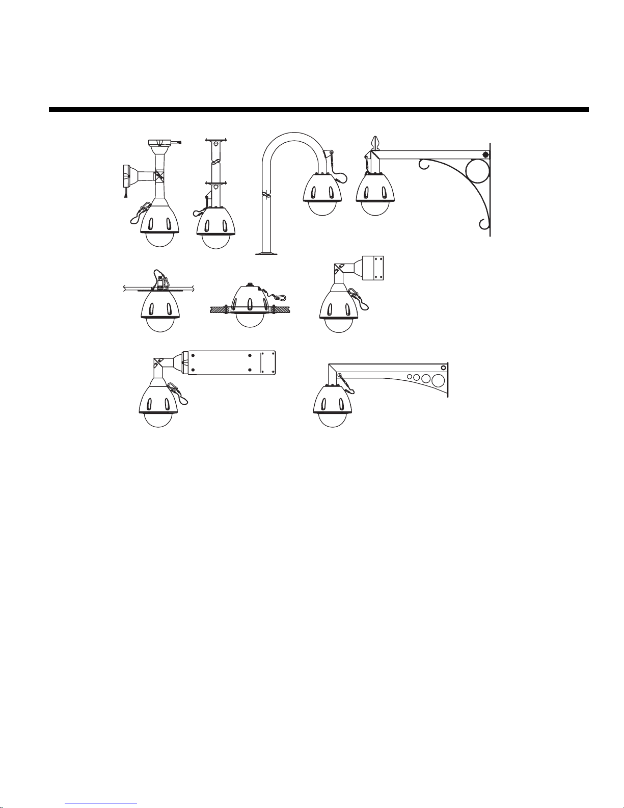
4. Mounting Configurations
With appropriate bracketry the Type 2060 dome enclosure can be mounted in any of the
orientations shown above.
1. Wall/Pendant Mount (order code 90002) giving pendant or wall mount options.
2. Pendant mount bracket (order code 90003) with drop length to suit customers requirements.
3. Snowdrop mount bracket (order code 90004) for mounting at the top of a pole or column.
4. Vintage mount bracket (order code 90005) for a vintage feel around historical buildings.
5. Ceiling mount bracket (order code 90006) for solid or suspended ceilings.
6. Tile mount (order code 90001) for suspended ceilings.
7. Corner Bracket (order code 90007) for mounting to corners of buildings in conjunction with
90002.
8. Extended corner bracket (order code 90008) for mounting to corners of buildings with 90002.
9. Extended wall mount (order code 90009) for extending out from a wall.
All bracket variants can be supplied with optional rain shield (order code 90010).
All mounting variants are suitable for both weatherproof ( IP66 BS EN 60529 ) & indoor units.
1.
2.
4.
5.
8.
Fig.2 Bracket mounting variants
3.
9.
6.
7.
Page 6

2060 Operation Manual Page. 4
5. Safety Bond
For wall, pendant & snowdrop mounted domes (wall mount shown in Fig.3). Clip carbine to the
mounting bracket eyelet (B) on flange of bracket to secure.(shown above).
For standard ceiling mounted domes attach the supplied safety bond, as shown in Fig.4. Fit bond
over M6 stud (position D) and secure with M6 nut, plain washer & spring washer supplied. Clip
carbine to eyelet (E) on dome to secure (see sheet 5 ‘Ceiling mounting instructions’ for details on
eyelet mounting).
Note: Always support dome with bond prior to mating connector (C). Weight of dome should be supported by
bond ensuring no stress is placed on centre connector (C) at any time.
Fig.3 Safety bond (Bracket mount)
Fig.4 Safety bond (Ceiling mount)
B
C
E
D
B
Page 7
2060 Operation Manual Page. 5
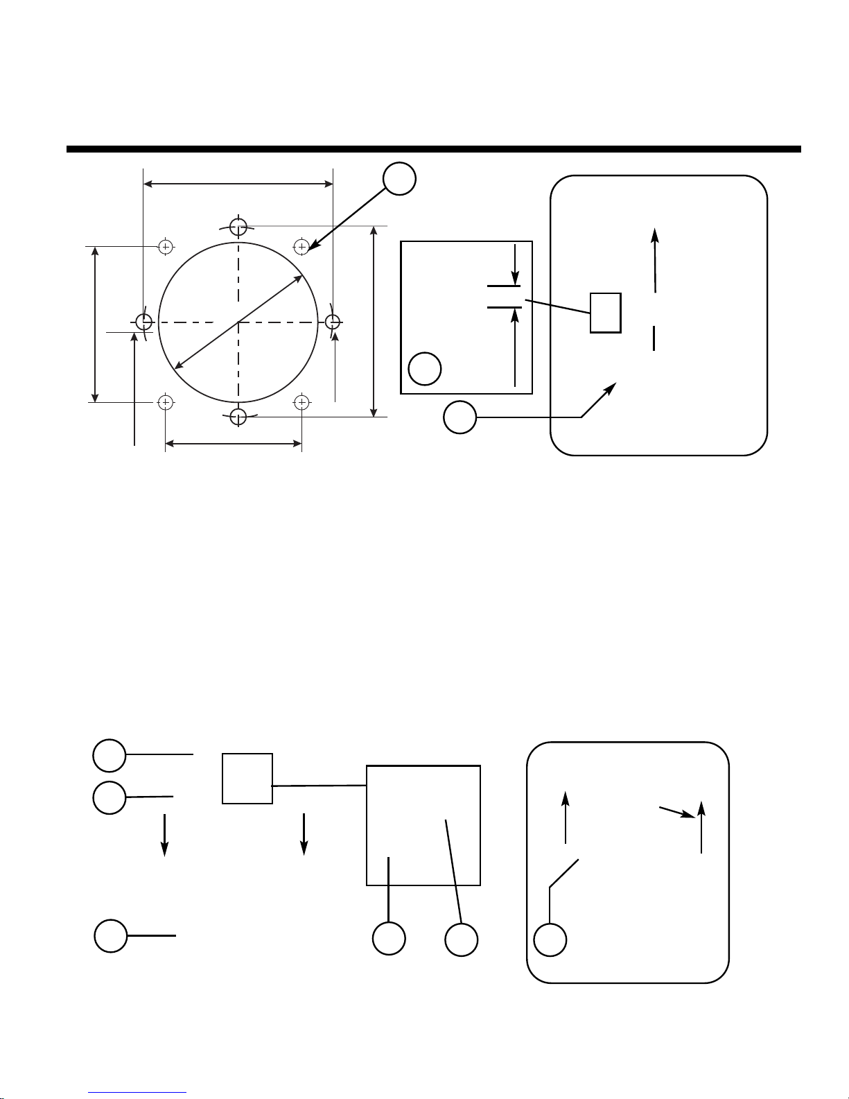
6. Ceiling Mounting
Cut/drill hole pattern in ceiling as shown in (fig.5) (Note: fixings for hole (A) are not supplied by
Dedicated Micros due to the variation of ceiling materials / thicknesses found on site. Please
choose suitable M6 fixings, with countersunk head, for your application.) Attach mounting disc (B)
to ceiling with chosen fixings and screw 4 off M6 x 16 soc cap hd. screws supplied into bushes as
shown (C). Attach transfer disc (E) to top of dome enclosure (G) with 4 off M6 dome hd. self tapping
trilobular screws (D) pre-fitted (fig.6) (Note: Fit safety bond bracket (F) as shown) Offer dome
enclosure to ceiling mounting disc (fig.7) engaging the screw heads (C) into keyhole slots (G).
Twist to locate and tighten fixings (C) to secure.
Please ensure safety bond is fitted as descibed on sheet 4.
Fig. 7
Fig.5 Ceiling hole pattern
5mm
B
C
D
E
G
D
F
G
Æ80mm-120mm
113mm
160mm
160mm
113mm
1 slot
Æ15mm
3 x 15mmÆ
4 x Ø6.5mm
A
Fig. 6
Page 8
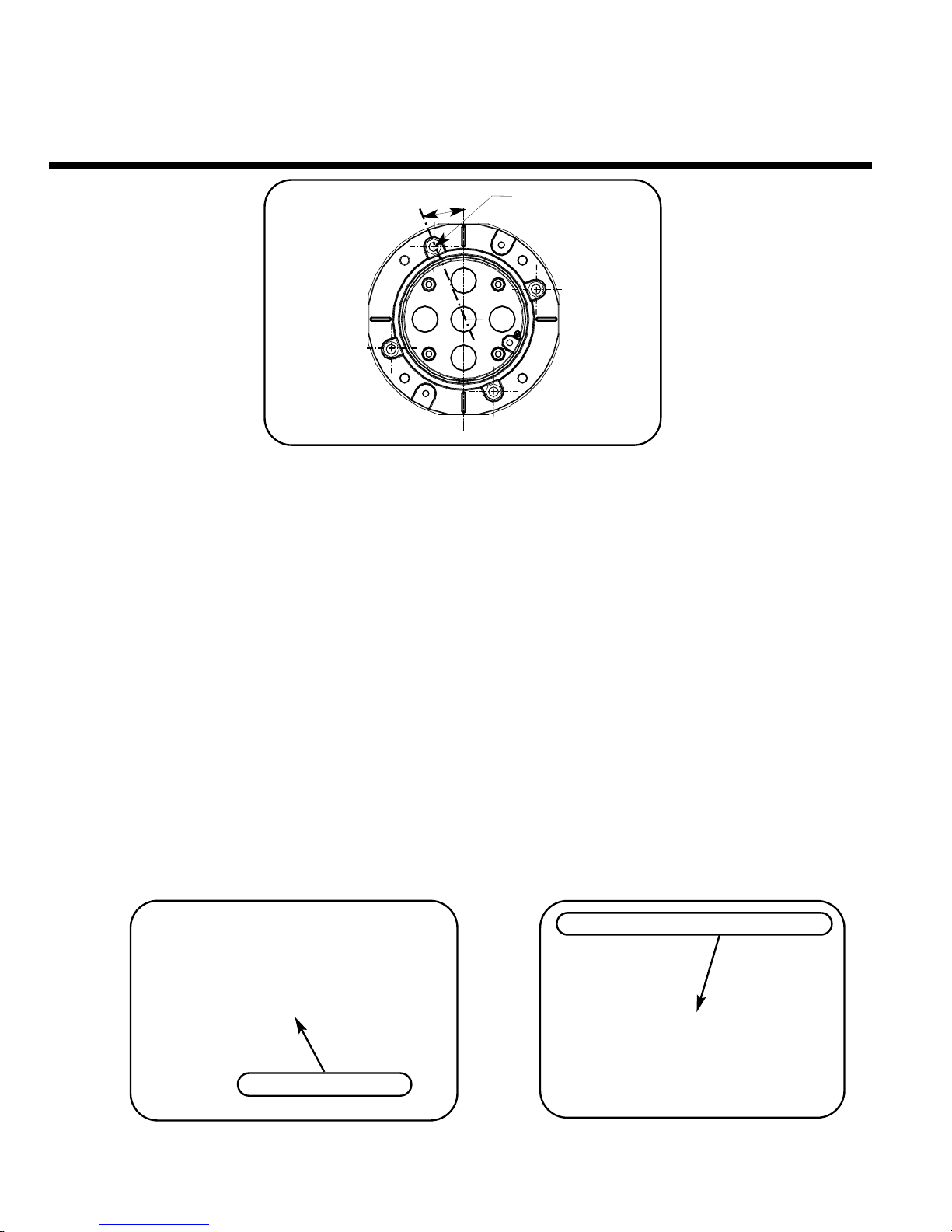
7. Wall Mounting Bracket
A. Remove bracket base casting by unscrewing outer trilobular fixings, then assuming masonry
wall mounting, mark & drill 4 x Ø7 holes using bracket base casting as pattern, shown above.To
assist with orientation flats are provided on all 4 axes allowing the use of a spirit level for
alignment. (Fig 8) (use goggles when drilling).
B. Insert 4 x M6 Rawlplugs into wall until flush.
C. Offer bracket base casting into position & screw wall fixing screws through into inserts.
D. Tighten fixings to secure. Note: An optional spreader plate (9011) is recommended when fixing
to brickwork to reduce the ‘pull out’ forces on a single brick.(Available from Dedicated Micros on
request).
Note: Locating a dome on a corner of a building will give an increased area of surveillance. For this application
Dedicated Micros are able to offer an optional corner bracket (9007) to adapt the standard wall bracket.
E. Thread cable from bracket through cable entry hole in bottom of bracket base casting, then fit
the bracket (Fig 9) (Note: bracket base casting can be orientated to position the entry hole to
either side or at the top.).
F. Using supplied trilobular fixings attach bracket to base casting as shown. (Fig 10).
2060 Operation Manual Page. 6
4 x Ø7mm
22.5º
Fig.8 Bracket Base Casting
Fig. 9
Fig. 10
Wall Fixing Screws
E
F
Outer Trilobular Fixings (M6 x 16)
Page 9

2060 Operation Manual Page. 7
8. Tile Mounting
Cut/drill hole pattern in tile as shown in (fig.11).
Attach the mounting disc to the dome as shown in (fig.12) using 3 of the existing M4 dome hd. self
tapping trilobular screws, that attach the hemisphere to the dome (item A).
Offer dome complete with attached mounting disc (item B) up to the hole in the tile from beneath
and clamp to tile using 2 off split clamp rings (items C) from above.
Secure mounting disc with 4 off M6 soc button hd. fixings (supplied) (item D) as shown in (fig.13).
Fit safety bond supplied (item E) to an attachment point in ceiling.
Note: For use with soffit mount the split clamp ring needs to be fixed into position using 4 off M4 pan hd. self
tapping fixings (supplied) (item F) (fig.14).
Fig.14 Split bezel mounting
Fig.11 Ceiling hole pattern
255mm
255mm
4 x Ø7mm
Ø215mm
Fig.12 Mounting disc attachment
A
E
D
F
C
B
Fig.13 Mounting to tile (ceiling)
Page 10

9. Dome Mounting
Fig.15 Mounting dome to bracket
A. Secure & hang dome to bracket by attaching safety bond carbine to eyelet, as shown.
B Mate central connector supplying power & control to dome. (ensure power is off when
connecting).
C. Lift dome to bracket flange ensuring head of screws (previously fitted M6x16 Trilobular self
tapping screws) pass through keyhole slots. Twist to locate.
D. Tighten 4 top mounting fixings with 4mm A/F Hexagonal key supplied to secure, finally secure
plasic cover to metal pins on bracket flange .
2060 Operation Manual Page. 8
B
A
C
D
Page 11
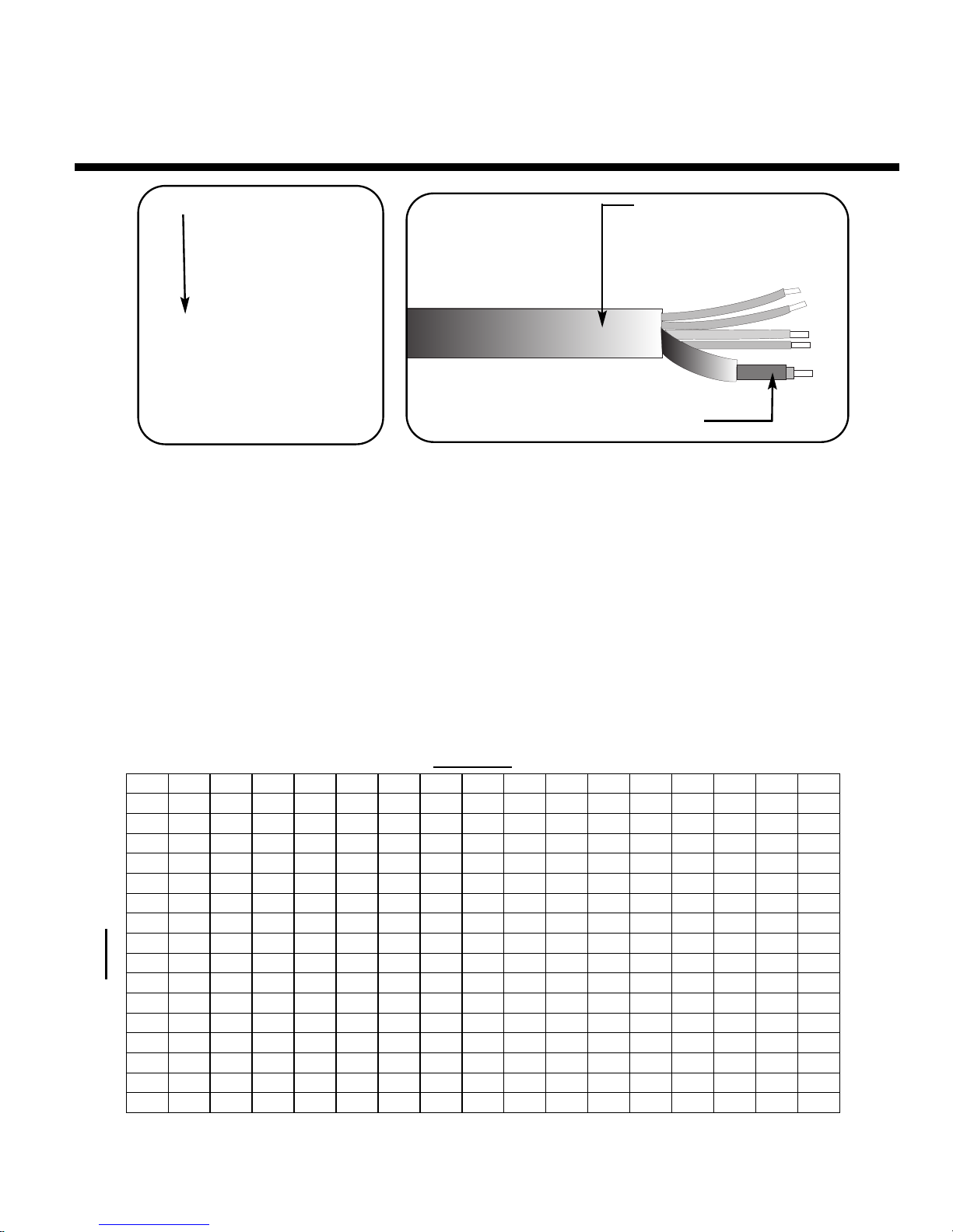
10. Electrical Connections
Fig.16 Electrical connections
The Type 2060 external connections are via an IP66 Amphenol connector with 3 metre composite
cable flying lead comprising co-ax, power pair & RS485 pair. This lead should be connected to the
boxed P.S.U. supplied with the dome (can be extended to 30 metres max. in length) The
connections are as follows:
The co-ax and power wires are always connected, the RS 485 wires are only connected when an
external protocol converter is fitted or an RS485 controller is being used.
2060 Operation Manual Page. 9
Red wire....24 V AC live
Blue wire..24 V AC neutral
Yellow wire.......R.S. 485 'A'
Green wire.......R.S. 485 'B'
Coax screen.......BNC screen
Coax signal........BNC centr pin
Fig.17 Address chart
Co-ax. (Video)
Multicore cable with
integral Co-ax (Video)
YELLOW
BLUE
ADDRESS SWITCHES
0 1 2 3 4 5 6 7 8 9 A B C D E F
0 0 1 2 3 4 5 6 7 8 9 10 11 12 13 14 15
1 16 17 18 19 20 21 22 23 24 25 26 27 28 29 30 31
2 32 33 34 35 36 37 38 39 40 41 42 43 44 45 46 47
3 48 49 50 51 52 53 54 55 56 57 58 59 60 61 62 63
4 64 65 66 67 68 69 70 71 72 73 74 75 76 77 78 79
5 80 81 82 83 84 85 86 87 88 89 90 91 92 93 94 95
6 96 97 98 99 100 101 102 103 104 105 106 107 108 109 110 111
7 112 113 114 115 116 117 118 119 120 121 122 123 124 125 126 127
8 128 129 130 131 132 133 134 135 136 137 138 139 140 141 142 143
9 144 145 146 147 148 149 150 151 152 153 154 155 156 157 158 159
A 160 161 162 163 164 165 166 167 168 169 170 171 172 173 174 175
B 176 177 178 179 180 181 182 183 184 185 186 187 188 189 190 191
C 192 193 194 195 196 197 198 199 200 201 202 203 204 205 206 207
D 208 209 210 211 212 213 214 215 216 217 218 219 220 221 222 223
E 224 225 226 227 228 229 230 231 232 233 234 235 236 237 238 239
F 240 241 242 243 244 245 246 247 248 249 250 251 252 253 254 255
Page 12

11. Address Switches
Address switches
The Type 2060 can be controlled via RS 485 commands
or ‘up the co-ax’.
With RS 485 control each dome has to be individually
addressed using the Blue and Yellow rotary address
switches following the address chart on the previous page.
For ‘up the co-ax’ control, using the built in protocol converter,
the same address switches are used to select the protocol
format for the controller being used e.g.
BAX AC PANEL.................Blue.F Yellow.C = 252
For: Baxall a.c. controllers
DEN PANEL.......................Blue.F Yellow.D = 253
For: Dedicated Micros, BBV & DM Sprite controllers
BAX DC PANEL................Blue.F Yellow.E = 254
For: Baxall d.c. controllers
For ‘up the co-ax’ control using external protocol converters like
the drx 100 or DAX-DEN the address switches should be set to
Blue.0 Yellow.1 = 1.
To access the address switches remove the outer hemisphere
and inner shroud as shown in A & B. Picture C shows the
location. This operation should be carried out in an office type
environment to avoid ingress of moist air.
2060 Operation Manual Page. 10
Fig.18
Address switches.
Address switches
A
C
B
Page 13

12. Control Configuration
2060 Operation Manual Page. 11
1 to 32 Dome Cameras
Video cable
RS 485
Data Link
(Daisy chain)
connect to
controller
Local
230Va.c
input
Local
230Va.c
input
Video cable
To Controller
PSU PSU
Fig.19 RS485 configuration
The Dedicated Micros 2060 dome can be
controlled by one of three methods.
Fig.19 RS485
Fig.20 Twisted Pair Configuration
Fig.21 Up the co-ax
The configuration drawings on this page
show the three connection arrangements.
2060 Domes are delivered with address
switches set at ...253 (DEN PANEL)
2060 with drx Domes are delivered with
address switches set at...1
1 to 16 Dome Cameras
Local
230Va.c. Input
Twisted Pair
(20mA)
(current loop)
4 x local
alarms
4 x local
alarms
Video cable
Video cable
To controller
drx 100
+PSU
drx 100
+PSU
Fig.20 Twisted Pair Configuration
1 to 16 Dome Cameras
Local
230Va.c.
Input
Local
230Va.c.
Input
Video cable
Video cable
To controller
PSU
PSU
Termination Resistor Link
Fitted - Resistor in (default)
Not fitted - Resistor out
Yellow
Address
Switch
Blue
Address
Switch
Fig.21 Up the co-ax Configuration
Page 14

13. Circuit Diagram
2060 Operation Manual Page. 12
RS485 / Up the Co-Ax Configuration
drx options
240V AC
I/P
L
E
N
500mA
FUSE
GN/YL
BR
RD
RD
9Vac 100mA
TO drx100 CARD
LINK J6/4-5 LOCAL ALARM HANDLING
LINK J6/1-2 STARTS SEQUENCE 1 AFTER 10 MINS INACTIVITY
FITTED CALL SEQUENCES
REMOVED CALL PRESET POSITIONS
VIDEO IN FROM DOME
VIDEO OUT TO TRANSMITTER
LIGHTS
SUPPLY IN
& DOME O/P
J6
J3
drx100 PCB ASSY.
9-12V
SUPPLY
J4
AC
C4
GND
GND
TP
A OUT
C2
A1
A3
AC
GND
C1
GND
TP
A OUT
C3
A2
A4
U2
or
TWISTED
PAIR 1/P
RS485
FROM DOME
ALARM O/P
ALARM I/P’s 4 OFF
GN
YL
J1
J5
POWER FROM
DOME
24Vac
2A5
BL
WH/RD
WH/RD
WH/BK
WH/BK
250mA
FUSE
9V
100mA
2Amp
FUSE
BK
240V
0V
BL
COAX TO
CONTROLLER
COAX FROM
DOME
DRAIN
WIRE NOT
CONNECTED
COMPOSITE CABLE
FROM DOME
POWER TO
DOME
RD
BL
YL
RS485 A
GR
RS485 B
TO DOME
FS2
2A
24Vac
2A5
L
L
E
E
N
N
RD
BR
FS1
500mA
240V AC
I/P
MAINS IN
CONNECT FOR
RS485 CONTROL ONLY
DO NOT CONNECT
FOR UP THE CO-AX CONTROL
24V
0V
BK
BL
240V
0V
N/U
Page 15

2060 Operation Manual Page. 13
ADDENDUM
Addendum 1. 2060 Fixed Attitude Dome
Camera
Addendum 2. 2060 Fixed Attitude (Electrical
Connections)
Addendum 3. 2060 Fixed Attitude (‘Zoom Cam’
Set Up)
Page 16

2060 (Fixed Attitude Dome Camera)
2060 Operation Manual Addendum 1
Moving cameras can be positioned remotely, fixed
attitude modules require manual adjustment to
position the camera. Follow the procedure below
to set-up your required picture frame.
1. Unscrew the 6 fixings securing the outer
hemisphere to the casing and remove.
2. To adjust the pan position of the camera, grip the
inner hemisphere and rotate. This adjustment
provides 180º of pan right & left movement. Tip. Do
not wind more than 180º in one direction as this will
stress the connections to the camera.
3. To adjust the tilt position grip the camera platform
(accessible through the camera viewing slot) as
shown and move. This adjustment provides tilt
up/down. See Addendum 3 for ‘zoom cam’ set-up.
1. Hemisphere removal
2. Camera pan adjustment
Inner hemisphere
3. Camera tilt adjustment
6 x fixing screws
Page 17

2060 (Fixed Attitude Connections)
The 2060 Fixed Attitude Camera Dome is supplied complete with an IP66 ‘Amphenol’ 7 way
connector and 3 metre multicore with Co-ax flying lead assembly. The Amphenol connector mates
as shown in fig.16 to the top of the dome. The table below details the flying lead functions.
2060 Operation Manual Addendum 2
Electrical connections
Red.... ..... 24 V AC live
Blue .........24 V AC neutral
Yellow ..... not used
Green ...... not used
Co-ax Screen ..... BNC screen
Co-ax Signal ..... BNC centre pin
VIDEO TO
MONITOR
VIDEO FROM
DOME
HEATER
SUPPLY
24Va.c.
MAINS
IN
24V
0V
0V
0V
10V
230V
BK
BL
BN
RD
FS1 2A
24Vac
FS2 500mA
230Vac I/P
L
L
E
E
N
N
P.S.U. Connection diagram
Co-ax. (Video)
Multicore cable with
integral Co-ax (Video)
Page 18

2060 (Fixed Attitude Electrical Connections)
Type 2060 Fixed Attitude ‘Zoom Cam’ is equipped with the ‘zoom cam’ high resolution
camera. See instructions below.
1. Control
Remote zoom control requires a Dedicated Micros, BBV or DM telemetry controller. as well as the removal of
link ‘A’ (see point 6) if not already disconnected. Depress the zoom buttons or use the joystick pan axis to
operate. If no control is available the camera can function as a ‘fixed lens’ (see point 6).
2. Presets
The ‘zoom cam’ can store up to 8, user definable, zoom presets within memory. Please refer to the relevant
controller instructions for preset programming.
3. Default position
After a period of inactivity (default 1min.) the ‘zoom cam’ will revert to preset 1 (wide angle if no preset stored).
On Dedicated Micros & BBV controllers only, use the ‘Patrol 2 delay program’ to adjust the time interval.
Intervals are 1,2,3,4,5,6,8 & 10 minutes for keys 1-8.
4. Patrol
The ‘zoom cam’ patrol feature can be used to sequence between the preset positions. Follow the relevant
controller instructions to setup ‘Patrol 1.’ Patrol mode is cancelled with any manual zoom action.
5. Video level adjustment
Video level is factory set, but can be adjusted by turning VR1, located just above the link’A’ on the receiver
board (see opposite). This adjustment may be required to lighten / darken the picture depending on the
distance of co-ax required.
6. Fixed lens
When no remote control is available the ‘zoom cam’ can function as a ‘fixed lens’ (i.e. the camera can be
manually zoomed (locally) to a preset position).
a. Ensure link ‘A’ (supplied) is fitted, as shown, between pins 9 & 10 on power up.
b. Frame the preset picture required by zooming, using the buttons provided on the side of the camera.
c. Temporarily remove the link ‘A’ for a few seconds and then refit. The link must be left in permanently.
Note: to revert back to ‘zoom cam’ operation the link must be removed and power re-applied.
2060 Operation Manual Addendum 3
zoom buttons
Link ‘A’ (shown fitted) between pins
9 & 10
Left side of camera
VR1 Video
adjustment
Right side of camera
Page 19

Notes
Page 20

Notes
Page 21

H A N D L E I D I N G
Page 22

Page 23

2060 Handleiding Blad. 1
1. Inleiding
Veel plezier met uw Dedicated Micros Series 2060 Precision Dome Camera.
Deze handleiding heeft betrekking op de modellen 2060, 2060 met drx, 2060 outdoor, 2060 outdoor
met drx en 2060 fixed attitude.
U vindt hierin alle informatie die nodig is voor installatie van de Series 2060 Precision Dome
Camera. Zie de handleiding Menusysteem voor de bedienings- en programmeerfuncties.
2. Index
1. Inleiding 1
2. Index 1
3. Inhoud 2
4. Montageconfiguraties 3
5. Veiligheidskabel 4
6. Standaard plafondmontage 5
7. Beugel voor wandmontage 6
8. Montage in plafondtegel 7
9. Dome monteren 8
10. Elektrische aansluitingen 9
11. Adresschakelaars 10
12. Besturingsconfiguratie 11
13. Schakelschema 12
14. Inhoud addendum 13
addendum 1. 2060 fixed attitude dome camera Addendum 1
addendum 2. 2060 fixed attitude aansluitingenaddendum Addendum 2
addendum 3. 2060 fixed attitude zoomcamera Addendum 3
Page 24

3. Inhoud
Geleverde componenten
Voor het installeren van de dome dient u de onderdelen uit de verpakking te nemen en te
controleren of alle onderstaande componenten aanwezig zijn.
1 x behuizing Series 2060 Dome (met veiligheidskabel)
1 x voedingseenheid
1 x connector losse bedrading
1 x tasje met de volgende onderdelen:
1 x 4 mm inbussleutel
1 x 5 mm inbussleutel (alleen Indoor)
4 x M6x16 inbusschroeven (alleen Indoor)
N.B. Montagebeugels kunnen afzonderlijk besteld en geleverd zijn.
Naast bovengenoemde componenten worden de volgende documenten geleverd.
2060 Handleiding Blad. 2
A
C
D
B
- Type 2060 Handleiding - Type 2060 Handleiding Snelle instellingen
- Type 2060 Handleiding Menusysteem - Laatste testprocedure Dedicated Micros
Page 25
4. Montageconfiguraties
Met de juiste beugels kan de behuizing voor Type 2060 dome op elke van de hierboven
afgebeelde wijzen worden gemonteerd.
1. Muur- of plafondmontage (bestelcode 90002) voor bevestiging aan muur of plafond.
2. Beugel voor plafondmontage (bestelcode 90003) met beugellengte naar wens van de klant.
3. Beugel voor staande montage (bestelcode 90004) bovenaan een paal of zuil.
4. Klassieke montagebeugel (bestelcode 90005) voor een ouderwetse aanblik bij historische
gebouwen.
5. Beugel voor plafondmontage (bestelcode 90006) voor massieve en verlaagde plafonds.
6. Beugel voor montage in plafondtegel (bestelcode 90001) voor verlaagde plafonds.
7. Hoekbeugel (bestelcode 90007) voor montage op hoeken van gebouwen en in combinatie met
90002.
8. Verlengde hoekbeugel (bestelcode 90008) voor montage op hoeken van gebouwen en in
combinatie met 90002.
9. Verlengde wandmontage (bestelcode 90009) voor grotere afstand vanaf wand.
Alle varianten van de beugels kunnen worden geleverd met een optionele regenkap (bestelcode
90010).
Alle montagevarianten zijn geschikt voor zowel weerbestendige ( IP66 BS EN 60529 ) als binnenshuis te
gebruiken installaties.
1.
2.
4.
5.
8.
Afb. 2 Montagevarianten voor beugels
3.
9.
6.
7.
2060 Handleiding Blad. 3
Page 26

2060 Handleiding Blad. 4
5. Veiligheidskabel
Voor aan de wand, aan het plafond en staand gemonteerde domes (Afb. 3 toont wandmontage).
Klem de karabijnhaak vast aan het oogje (B) op de flens van de montagebeugel (zie hierboven).
Bij standaard aan plafond gemonteerde domes bevestigt u de geleverde veiligheidskabel zoals Afb.
4 laat zien. Bevestig de kabel aan de M6-bout (positie D) en zet hem vast met de meegeleverde
M6-moer, de gladde ring en de veerring. Klem de karabijnhaak vast aan het oogje (E) op de dome
om hem te bevestigen (zie blad 5 'Instructies voor plafondmontage' voor bijzonderheden over de
montage van het oogje).
Opmerking: Laat de dome altijd aan de kabel steunen voordat u de connector (C) aansluit. Het gewicht van de
dome moet door de kabel worden gedragen om te zorgen dat er nooit trekkracht op de centrale connector (C)
wordt uitgeoefend.
Afb. 3 Veiligheidskabel (beugelmontage)
Afb. 4 Veiligheidskabel (plafondmontage)
B
C
E
D
B
Page 27

2060 Handleiding Blad. 5
6. Plafondmontage
Zaag en boor de gaten in het plafond zoals aangegeven in afb. 5. (Opmerking:
bevestigingsmaterialen voor gat (A) worden niet door Dedicated Micros geleverd, omdat de aard
en dikte van de ter plaatse toegepaste plafondmaterialen aanzienlijk kunnen verschillen. Kies
geschikte M6-bevestigingsmaterialen met verzonken kop.) Bevestig de montageschijf (B) met
geschikte materialen aan het plafond en draai de vier M6 x 16 meegeleverde inbusschroeven op de
aangegeven wijze (C) in de bussen. Bevestig de montageschijf (E) aan de bovenzijde van de
domebehuizing (G) met 4 M6 vooraf gemonteerde zelftappende schroeven (D) (afb. 6) (Opmerking:
Bevestig het oog voor de veiligheidskabel (F) zoals op de afbeelding is aangegeven.) Bevestig de
behuizing aan de montageschijf aan het plafond (afb. 7) en laat de schroefkoppen (C) in de
schroefsleuven vallen (G). Draai de behuizing op zijn plaats en zet deze met de inbusschroeven (C)
vast.
Zorg dat de veiligheidskabel is bevestigd zoals in blad 4 is beschreven.
Afb. 7
Afb. 5 Sjabloon voor gat in plafond
5mm
B
C
D
E
G
D
F
G
Æ80mm-120mm
113mm
160mm
160mm
113mm
1 slot
Æ15mm
3 x 15mmÆ
4 x Ø6.5mm
A
Afb. 6
Page 28

7. Beugel voor wandmontage
A. Verwijder de steunplaat voor de beugel door de buitenste zelftappende schroeven los te draaien.
Gebruik de steunplaat als sjabloon om vervolgens, bij wanden van metselwerk, 4 gaten van Ø7
te markeren en deze gaten te boren zoals hierboven is aangegeven. Om het bepalen van de
juiste hoek te vergemakkelijken zijn vier vlakke stukken aangebracht als steun voor een
waterpas. (Afb. 8) (Gebruik een veiligheidsbril bij het boren.)
B. Steek 4 x M6-pluggen volledig in de wand.
C. Zet de steunplaat in de juiste positie en draai de bevestigingsschroeven door de gaten heen.
D. Zet de schroeven vast.
Opmerking:
Als de trekkrachten slechts op één steen worden uitgeoefend, wordt toepassing van een optionele
spreidingsplaat (9011) aanbevolen. (Op aanvraag verkrijgbaar bij Dedicated Micros.)
Opmerking: Het bewaakte gebied wordt vergroot als de dome op de hoek van een gebouw wordt geplaatst. Voor
deze toepassing kan Dedicated Micros een optionele hoekbeugel (9007) leveren om de standaard wandbeugel
aan te passen.
E. Trek de kabel van de beugel door het kabelgat in de bodem van de steunplaat en zet de beugel
vast. (Afb. 9)
(Opmerking: De steunplaat kan zó gedraaid worden dat het kabelgat zich aan een van beide zijkanten of aan de
bovenzijde bevindt.)
F. Bevestig de beugel met de zelftappende schroeven aan de steunplaat zoals is aangegeven.
(Afb. 10)
2060 Handleiding Blad. 6
4 x Ø7mm
22.5º
Afb. 8 Steunplaat voor beugel
Afb. 9
Afb. 10
Schroeven voor bevestiging
E
F
Buitenste zelftappende schroeven (M6 x 16)
Page 29

8. Montage in plafondtegel
Zaag en boor de gaten in het plafond zoals aangegeven (afb. 11).
Bevestig de montageschijf aan de dome zoals aangegeven (afb. 12). Gebruik daarvoor drie van de
aanwezige M4 zelftappende schroeven met bolle kop, waarmee de halve bol aan de dome wordt
bevestigd (item A).
Plaats de dome compleet met de daaraan bevestigde montageschijf (item B) van onder af in het
gat van de tegel en klem de dome hierin van boven af vast met twee klemringen (items C).
Zet de montageschijf vast met vier meegeleverd M6 inbusschroeven (item D) zoals aangegeven
(afb. 13).
Bevestig de meegeleverde veiligheidskabel (item E) aan een bevestigingspunt in het plafond.
Opmerking: Bij montage aan de onderzijde moet de klemring op zijn plaats worden gezet met 4 meegeleverde
zelftappende M4-schroeven (item F) (afb. 14).
Afb. 14 Verzonken montage
Afb. 11 Sjabloon voor gat in plafond
255mm
255mm
4 x Ø7mm
Ø215mm
Afb. 12 Bevestiging van montageschijf
A
E
D
F
C
B
Afb. 13 Montage in plafondtegel
2060 Handleiding Blad. 7
Page 30
9. Dome monteren
Afb. 15 Dome aan beugel monteren
A. Hang de dome aan de beugel en zet hem vast door de karabijnhaak van de veiligheidskabel
aan het oog te bevestigen zoals aangegeven.
B. Sluit de centrale connector voor voeding en besturing aan op de dome. (Zorg dat de voeding is
uitgeschakeld tijdens het aansluiten.)
C. Til de dome in de beugelflens en zorg dat de schroefkoppen (van de tevoren bevestigde M6 x
16 zelftappende schroeven) in de schroefsleuven vallen. Draai de dome op zijn plaats.
D. Draai de 4 inbusschroeven met de meegeleverde 4 mm inbussleutel vast en druk tenslotte de
plastic deksel op de metalen pennen van de beugelflens.
2060 Handleiding Blad. 8
B
A
C
D
Page 31

10. Elektrische aansluitingen
Afb. 16 Elektrische aansluitingen
De externe aansluitingen van Type 2060 lopen via een IP66 amphenol-connector met 3 meter losse
samengestelde kabel bestaande uit coax-, voedings- en RS485-kabels. Deze kabel moet worden
aangesloten op de voedingseenheid die bij de dome geleverd is (en kan tot max. 30 m worden
verlengd). De aansluitingen zijn de volgende:
De coax en voedingskabels zijn altijd aangesloten. De RS 485-kabels zijn alleen aangesloten als
een externe protocolconverter is gemonteerd of een RS485-controller wordt gebruikt.
2060 Handleiding Blad. 9
Rode draad....24 V AC voeding
Blauwe draad..24 V AC nulleiding
Gele draad.......R.S. 485 'A'
Groene draad.......R.S. 485 'B'
Coax afscherming..BNC afscherming
Coax signaal........BNC centrale pen
Afb. 17 Adreskaart
Coax (video)
Meeraderige kabel
met geïntegreerde
coax (video)
GEEL
BLAUW
ADRESSCHAKELAARS
0 1 2 3 4 5 6 7 8 9 A B C D E F
0 0 1 2 3 4 5 6 7 8 9 10 11 12 13 14 15
1 16 17 18 19 20 21 22 23 24 25 26 27 28 29 30 31
2 32 33 34 35 36 37 38 39 40 41 42 43 44 45 46 47
3 48 49 50 51 52 53 54 55 56 57 58 59 60 61 62 63
4 64 65 66 67 68 69 70 71 72 73 74 75 76 77 78 79
5 80 81 82 83 84 85 86 87 88 89 90 91 92 93 94 95
6 96 97 98 99 100 101 102 103 104 105 106 107 108 109 110 111
7 112 113 114 115 116 117 118 119 120 121 122 123 124 125 126 127
8 128 129 130 131 132 133 134 135 136 137 138 139 140 141 142 143
9 144 145 146 147 148 149 150 151 152 153 154 155 156 157 158 159
A 160 161 162 163 164 165 166 167 168 169 170 171 172 173 174 175
B 176 177 178 179 180 181 182 183 184 185 186 187 188 189 190 191
C 192 193 194 195 196 197 198 199 200 201 202 203 204 205 206 207
D 208 209 210 211 212 213 214 215 216 217 218 219 220 221 222 223
E 224 225 226 227 228 229 230 231 232 233 234 235 236 237 238 239
F 240 241 242 243 244 245 246 247 248 249 250 251 252 253 254 255
Page 32

11. Adresschakelaars
Adresschakelaars
Type 2060 kan bestuurd worden met RS 485-opdrachten
of via de coax.
Met RS 485-besturing moet elke dome afzonderlijk met
de roterende Blue en Yellow adresschakelaars worden
geadresseerd aan de hand van de adreskaart op de vorige
pagina. Voor besturing via de coax met de ingebouwde
protocolconverter worden dezelfde adresschakelaars
gebruikt om het protocolformaat voor de gebruikte controller
te selecteren, bijvoorbeeld:
BAX AC PANEL.................Blauw.F Geel.C = 252
voor Baxall AC controllers
DEN PANEL.......................Blauw.F Geel.D = 253
voor Dedicated Micros, BBV en DM Sprite-controllers
BAX DC PANEL................Blauw.F Geel.C = 254
voor Baxall DC controllers
Voor besturing via de coax met externe protocolconverters
als de drx 100 of DAX-DEN moeten de adresschakelaars
worden ingesteld op Blauw.0 Geel.1 = 1.
Om de adresschakelaars te bereiken moet u de buitenste
halve bol en het binnenste omhulsel verwijderen zoals in
A en B is aangegeven.
Afbeelding C toont de positie. Deze bewerking moet in
een kantooromgeving worden uitgevoerd om te
voorkomen dat vochtige lucht de dome binnendringt .
2060 Handleiding Blad. 10
Afb.18 Adresschakelaars
Adresschakelaars
A
C
B
Page 33

12. Besturingsconfiguratie
2060 Handleiding Blad. 11
1 tot 32 dome-camera's
Videokabel
RS485-aansluiting
gegevenskoppeling
(ringnetwerk) op controller
Lokale
ingang
230 V AC
Lokale
ingang
230 V AC
Videokabel
Naar controller
PSU PSU
Afb. 19 Configuratie RS485
De Dedicated Micros 2060-dome kan op
een van drie manieren worden bestuurd.
Afb. 19 RS485
Afb. 20 Twisted pair-configuratie
Afb. 21 Via coax
De configuratietekeningen op deze pagina
tonen de drie aansluitschema's.
2060 Domes worden geleverd met
adresschakelingen die op ...253 (DEN
PANEL) zijn ingesteld.
2060 met drx-domes worden geleverd met
adresschakelingen die op ...1 zijn ingesteld.
1 tot 16 dome-camera's
Lokale
ingang 230 V AC
Twisted pair
(20 mA)
(huidige lus)
4x lokale
alarmen
4x lokale
alarmen
Videokabel
Videokabel
Naar controller
drx 100
+PSU
drx 100
+PSU
Afb. 20 Twisted pair-configuratie
1 tot 16 dome-camera's
Lokale
ingang
230 V AC
Lokale
ingang
230 V AC
Videokabel
Videokabel
Naar controller
PSU
PSU
Koppeling afsluitweerstand
Aanwezig - Weerstand aan (standaard)
Niet aanwezig - Weerstand uit
Gele
adresschakelaar
Blauwe
adresschakelaar
Afb. 21 Configuratie via coax
Page 34

13. Schakelschema
2060 Handleiding Blad. 12
RS485 / Configuratie via coax
drx-opties
240V AC
INGANG
L
E
N
500mA
ZEKERING
GN/YL
BR
RD
RD
9Vac 100mA
NAAR drx100-KAART
VERBINDING J6/4-5 LOKALE ALARMAFHANDELING
VERBINDING J6/1-2 START SEQUENTIE 1 NA 10 MINUTENT INACTIVITEIT
GESLOTEN VERBINDING: SEQUENTIES OPROEPEN
OPEN VERBINDING: VOORINGESTELDE POSITIE OPROEPEN
VIDEO-INGANG VAN DOME
VIDEO-UITGANG NAAR ZENDER
VOEDINGSINGANG
VERLICHTING
& DOME UITGANG
J6
J3
drx100 PCB ASSY.
9-12V
VOEDING
J4
AC
C4
GND
GND
TP
A OUT
C2
A1
A3
AC
GND
C1
GND
TP
A OUT
C3
A2
A4
U2
or
GETWIST
ADERPAAR
INGANG
RS485
VAN DOME
ALARMUITGANG
ALARM INGANGEN 4 UITGESCHAKELD
GN
YL
J1
J5
VOEDING VAN
DOME
24Vac
2A5
BL
WH/RD
WH/RD
WH/BK
WH/BK
250mA
ZEKERING
9V
100mA
2Amp
ZEKERING
BK
240V
0V
BL
COAX NAAR
CONTROLLER
COAX VAN
DOME
DRAIN-WIRE
NIET AANGESLOTEN
COMPOSIET-KABEL
VAN DOME
VOEDING
NAAR
DOME
RD
BL
YL
RS485 A
GR
RS485 B
NAAR DOME
FS2
2A
24Vac
2A5
L
L
E
E
N
N
RD
BR
FS1
500mA
240V AC
INGANG
VOEDINGSINGANG
ALLEEN AANSLUITEN BIJ RS48
BUSCONTROLE
NIET AANSLUITEN BIJ UTC/UP-THE-COAX
CONTROLE
24V
0V
BK
BL
240V
0V
N/U
Page 35

2060 Handleiding Blad. 13
ADDENDUM
Addendum 1. 2060 Fixed attitude dome-camera
Addendum 2. 2060 Fixed attitude (elektrische
aansluitingen)
Addendum 3. 2060 Fixed attitude (instelling
zoomcamera)
Page 36

2060 (Fixed attitude dome-camera)
2060 Handleiding Addendum 1
De positie van bewegende camera's kan op
afstand worden ingesteld; bij fixed attitudemodules moet dat handmatig gebeuren. Volg
onderstaande procedure om het gewenste
beeldkader van de camera in te stellen.
1. Draai de 6 schroeven los waarmee de buitenste
halve bol aan de behuizing is bevestigd en neem
de halve bol los.
2. Stel de draairichting van de camera in door de
binnenste halve bol te verdraaien. U kunt 180º naar
links en naar rechts draaien. Tip. Draai niet meer
dan 180º in één richting; anders komen de
aansluitingen op de camera strak te staan.
3. Om de kanteling van de camera in te stellen pakt u
op de aangegeven wijze de voet van de camera
(bereikbaar via de cameraopening) en beweegt u
de voet omhoog of omlaag. Deze aanpassing
bepaalt de tilt van de camera. Zie Addendum 3 voor
instelling van een zoomcamera.
1. Halve bol verwijderen
2. Opnamerichting instellen
Binnenste halve bol
3. Kanteling instellen
6 x bevestigingsschroeven
Page 37

2060 (Fixed Attitude Elektrische aansluitingen)
De 2060 Fixed Attitude dome-camera wordt geleverd met een IP66 'Amphenol' 7-pens connector
en 3 meter meeraderige kabel met losse coaxbedrading. De amphenolconnector past aan de
bovenzijde op de dome zoals afb. 16 laat zien. Onderstaande tabel geeft de details van de functies
van de losse bedrading.
2060 Handleiding Addendum 2
Elektrische aansluitingen
Rood ..... 24 V AC voeding
Blauw .....24 V AC nul
Geel ..... niet in gebruik
Groen ..... niet in gebruik
Coax afscherming ..... BNC-afscherming
Coax signaal ..... BNC centrale pen
VIDEO NAAR
MONITOR
VIDEO VAN
DOME
VOEDING VOOR
VERWARMING
24Va.c.
VOEDINGSINGANG
24V
0V
0V
0V
10V
230V
BK
BL
BN
RD
FS1 2A
24Vac
FS2 500mA
230Vac INGANG
L
L
E
E
N
N
Aansluitschema voeding
Coax (video)
Meeraderige kabel
met geïntegreerde
coax (video)
Page 38

2060 (Fixed Attitude Elektrische aansluitingen)
Type 2060 Fixed Attitude zoomcamera is voorzien van de 'zoom cam' met hoge resolutie. Zie
onderstaande instructies.
1. Bediening
Voor externe bediening van de zoomlens is een telemetriecontroller van Dedicated Micros, BBV of DM nodig
en moet koppeling 'A' worden verwijderd (zie punt 6) als dat nog niet gebeurd is. Druk op de zoomknoppen of
gebruik de panningfunctie voor de bediening. Als deze bedieningsmogelijkheden niet aanwezig zijn, kan de
camera functioneren met vaste lens (zie punt 6).
2. Voorkeursinstellingen
De 'zoom cam' kan 8 door de gebruiker gekozen zoominstellingen in het geheugen opslaan. Zie de
desbetreffende controllerinstructies voor het programmeren van de presets.
3. Standaardpositie
Als de zoomcamera een bepaalde periode (standaard 1 min.) niet actief is geweest, keert hij terug in preset 1
(groothoek als geen instelling is opgeslagen). Alleen op controllers van Dedicated Micros en BBV kunt u met
het 'Patrol 2 delay program' de inactiviteitsperiode instellen.
Mogelijkheden zijn 1,2,3,4,5,6,8 en 10 minuten met de toetsen 1-8.
4. Patrol
The ‘zoom cam’ patrol feature can be used to sequence between the preset positions. Follow the relevant
controller instructions to setup ‘Patrol 1.’ Patrol mode is cancelled with any manual zoom action.
5. Videosignaal aanpassen
De sterkte van het videosignaal is in de fabriek ingesteld maar kan worden aangepast door de knop VR1 te
verdraaien die zich vlak boven koppeling 'A' op de ontvangerkaart bevindt (zie ommezijde). Deze aanpassing
kan vereist zijn om het beeld helderder of donkerder te maken, afhankelijk van de lengte van de nodige
coaxkabel.
6. Vaste lens
Als geen afstandsbediening beschikbaar is kan de zoomcamera als 'vaste lens' fungeren (d.w.z. dat de
camera - ter plaatse - handmatig op een vooraf gekozen positie moet worden ingezoomd).
a. Zorg dat bij het inschakelen de koppeling 'A' (geleverd) is aangebracht tussen de pennen 9 en 10, zoals
afgebeeld.
b. Stel het door inzoomen gewenste beeldkader vooraf in met de knoppen aan de zijkant van de camera.
c. Verwijder de koppeling 'A' gedurende enkele seconden en breng hem daarna weer aan. De koppeling moet
permanent aanwezig blijven.
Opmerking: U kunt de zoomfunctie van de camera weer herstellen door de koppeling te verwijderen en de
voeding weer in te schakelen.
2060 Handleiding Addendum 3
zoomknoppen
Koppeling 'A' (aangebracht op afbeelding)
tussen de pennen 9 en 10
Linkerzijde van camera
Instelling
videosignaal
VR1
Rechterzijde van camera
Page 39

Opmerkingen
Page 40

Opmerkingen
Page 41

MANUEL D’INSTALLATION
Page 42

Page 43

2060 Manuel d'installation Page. 1
1. Introduction
Merci d'avoir choisi la caméra dôme Dedicated Micros série 2060. Les modèles concernés par ce
document sont les suivants : 2060, 2060 avec Drx, 2060 extérieur, 2060 extérieur avec Drx et 2060
fixe.
Ce manuel d'installation fournit toutes les informations nécessaires à l'installation des produits
précités. Pour les fonctions opérationnelles et de programmation, se reporter au manuel d’utilisation
et de paramétrage.
2. Index
1. Introduction 1
2. Index 1
3. Liste des éléments 2
4. Configurations de montage 3
5. Elingue de sécurité 4
6. Montage plafond 5
7. Support mural 6
8. Montage sur dalle de faux plafond 7
9. Montage du dôme 8
10. Raccordements électriques 9
11. Commutateurs d'adressage 10
12. Configurations de commande 11
13. Schémas 12
14. Annexes 13
Annexe 1. Caméra dôme à réglage manuel Annexe 1
Annexe 2. Caméra dôme à réglage manuel (raccordements électriques) Annexe 2
Annexe 3. Caméra dôme à réglage manuel (paramétrage "Zoom") Annexe 3
Page 44

3. Liste des éléments
Eléments fournis
Avant de procéder à l'installation, déballez l'ensemble des éléments du carton et vérifiez que
chaque objet décrit dans la liste suivante est bien présent :
1 x caisson dôme série 2060 (avec élingue de sécurité)
1 x alimentation
1 x un cordon de raccordement
1 x un sachet contenant les éléments suivants :
1 x clé Allen 4 mm
1 x clé Allen 5 mm (version intérieure uniquement)
4 x vis M6 x 16 (version intérieure uniquement)
N.B. L'ensemble des éléments de support peut être commandé et livré séparément.
En plus des composants décrits ci-dessus, les documents suivants sont fournis :
2060 Manuel d'installation Page. 2
A
C
D
B
- Manuel d'installation 2060 - Guide d'installation rapide 2060
- Manuel d’utilisation et de paramétrage - Procédure de test final Dedicated Micros
Page 45

2060 Manuel d'installation Page. 3
4. Configurations de montage
Grâce au support approprié, le caisson de la caméra dôme 2060 peut être fixé dans
n'importe laquelle des orientations présentées ci-dessus.
1. Fixation murale/suspendue (réf. 90002) en indiquant le type d'option choisi.
2. Fixation suspendue (réf. 90003) en indiquant la longueur de suspension
répondant aux exigences du client.
3. Support anti-neige (réf. 90004) pour fixation sur un poteau ou une colonne.
4. Support aspect ancien (réf. 90005) notamment pour les monuments historiques.
5. Support (réf. 90006) pour plafond en dur ou suspendu.
6. Support (réf. 90001) pour dalle de faux-plafond.
7. Support (réf. 90007) pour fixation en angle d'immeubles, associé avec la réf
90002
8. Support rallongé (réf. 90008) pour fixation en angle d'immeubles, associé avec
la réf 90002
9. Support rallongé (réf. 90009) pour fixation avec écartement par rapport au mur.
Tous les types de support peuvent être fournis avec un pare soleil optionnel (réf. 90010)
Tous les types de support sont utilisables avec les dispositifs extérieurs (étanche IP66 - BS
EN 60529) et intérieurs.
1.
2.
4.
5.
8.
Fig.2
3.
9.
6.
7.
Page 46

2060 Manuel d'installation Page. 4
5. Elingue de sécurité
Dispositif prévu pour les dômes muraux, suspendus ou sur poteau (version murale Fig.3).
Accrochez le mousqueton de l'élingue à l'œillet (B) présent sur le côté du support pour sécuriser
l'ensemble (voir ci-dessus).
Pour les dômes plafond standards, attachez l'élingue comme indiqué Fig.4. Placez la boucle
d'élingue sur le goujon M6 (D) et bloquez à l'aide de la rondelle plate, de la rondelle grower et de
l'écrou M6 fournis. Accrochez le mousqueton à l'œillet (E) sur support dôme pour sécuriser
l'ensemble (voir page 5). "Instructions de montage au plafond" pour le passage dans l'œillet.
Note : sécurisez toujours le support dôme avec l'élingue avant de procéder au raccordement (C). Le poids du
dôme doit être supporté par l'élingue, afin de s'assurer qu'aucune tension n'est exercée à aucun moment sur le
connecteur central (C).
Fig.3 Elingue de sécurité (fixation support)
Fig.4 Elingue de sécurité (fixation plaford)
B
C
E
D
B
Page 47

2060 Manuel d'installation Page. 5
6. Montage plafond
Marquez et percez le plafond selon l'indication du gabarit (Fig.5). Note : les accessoires de fixation
pour les trous (A) ne sont pas fournis étant donné la diversité des matériaux et épaisseurs des
constituants de plafond d'un site. Choisissez les vis M6 adéquates, avec tête cruciforme adaptées à
l'application. Fixez le disque de montage (B) au plafond avec les accessoires et 4 vis M6 x 16 CHC
fournies en les introduisant dans les ouvertures, comme indiqué (C). Fixez le disque de transfert
(E) en partie haute du caisson du dôme (G) à l'aide des 4 vis M6 CHC (D) prémontées (Fig. 6).
Note : accrochez l'élingue de sécurité du support (F) comme indiqué. Présentez le caisson du
dôme sur le disque de fixation (fig. 7) en faisant entrer les têtes des vis CHC (C) dans les trous
oblongs (G). Effectuez une rotation et serrer les vis (C) pour bloquer l'ensemble en position.
Assurez-vous que l'élingue de sécurité est bien en place comme indiqué à la page 4.
Fig. 7
Fig.5 Gabarit de perçage version plaford
5mm
B
C
D
E
G
D
F
G
Æ80mm-120mm
113mm
160mm
160mm
113mm
1 slot
Æ15mm
3 x 15mmÆ
4 x Ø6.5mm
A
Fig. 6
Page 48

7. Support mural
A. Retirez l'embase du support en ôtant les vis tête bombée CH extérieures, puis après s'être
assuré de la fixation murale sur la maçonnerie, marquez et percez 4 trous Ø 7 mm en vous
servant de l'embase comme gabarit (présentée ci-dessus). Pour vérifier l'orientation, il existe
des parties planes aux 4 axes permettant l'emploi d'un niveau pour l'alignement (Fig. 8). Utilisez
des lunettes de protection lors du perçage.
B. Insérez 4 chevilles M6 dans le mur jusqu'à affleurement.
C. Mettez en place l'embase et fixez celle-ci au mur à l'aide de vis introduites dans les trous prévus
à cet effet.
D. Serrez les vis pour bloquer l'ensemble en position. Note : l'utilisation d'une plaque d'espacement
optionnelle (réf. 9011) est recommandée lors de la fixation sur un briquetage afin de réduire
l'effort de traction sur une brique unique (disponible sur demande).
Note : la fixation du dôme en angle d'un immeuble permet d'augmenter la zone de surveillance. Pour ce type
d'application, il existe un support optionnel approprié (9007) qui s'adapte sur le support mural standard.
E. Introduisez le câble du support dans la découpe prévue à cet effet sur l'embase, puis fixez le
support (Fig 9). Note : l'embase peut être orientée pour positionner la découpe de passage de
câble soit sur le côté, soit sur le dessus.
F. A l'aide des vis tête bombée CH, fixez le support sur son embase comme indiqué (Fig 10).
2060 Manuel d'installation Page. 6
4 x Ø7mm
22.5º
Fig.8 Disposition de l’embase du support
Fig. 9
Fig. 10
Vis tête bombée CH (M6 x 16)
E
F
Vis de fixation murale
Page 49

2060 Manuel d'installation Page. 7
8. Support sur dalle de faux-plafond
Marquez et percez le trou dans la dalle grâce au gabarit comme indiqué ci-dessus (Fig. 11).
Fixer le disque de montage comme indiqué (Fig. 12) en utilisant 3 des vis M4 tête bombée CH
autotaraudeuses qui solidarisent la bulle au dôme (élément A).
Présentez par le dessous le dôme équipé de son disque de montage (élément B) dans le trou
pratiqué dans la dalle et maintenez en place l'ensemble par le dessus, sur ladite dalle, grâce à la
collerette en 2 parties (éléments C).
Fixez le disque de montage à l'aide des 4 vis M6 fournies (élément D) comme indiqué Fig. 13.
Mettez en place l'élingue de sécurité fournie (élément E) à un point d'ancrage dans le faux plafond.
Note : lorsque le support plafond est utilisé, la collerette en 2 parties doit être fixée en position grâce aux 4 vis
autotaraudeuses (fournies) (élément F) (Fig. 14).
Fig.14 Collerette démontable
Fig.11 Gabarit de perçage (version plafond)
255mm
255mm
4 x Ø7mm
Ø215mm
Fig.12 Fixation du disque de montage
A
E
D
F
C
B
Fig.13 Mintage sur plaque (plafond)
Page 50

9. Montage du dôme
Fig.15 Montage du dôme sur le support
A. Sécurisez le dôme en accrochant l'élingue sur l'œillet du support comme indiqué ci-dessus.
B. Le connecteur mâle central fournit l'alimentation et les commandes au dôme (assurez-vous que
l'alimentation est interrompue lors du branchement).
C. Faites remonter le dôme vers le support en vous assurant que les vis (tête bombée CH M6 x
16) passent au travers des trous oblongs. Effectuez une rotation pour bloquer l'ensemble en
position.
D. Serrez les 4 vis précédemment indiquées à l'aide de la clé Allen 4 mm fournie, puis faites
descendre la coupelle en plastique sur les broches métalliques de la partie fixation.
2060 Manuel d'installation Page. 8
B
A
C
D
Page 51

10. Raccordements électriques
Fig.16 Raccordements électriques
Les connexions externes du dôme 2060 s'effectuent via un connecteur Amphenol IP66 équipé d'un câble
composite d'une longueur de 3 m. Ce dernier comprend 1 câble coaxial et 2 paires de conducteurs, l'une pour
l'alimentation et l'autre pour la liaison RS-485. Le câble composite doit être raccordé au boîtier d'alimentation
fourni avec le dôme (sa longueur peut être étendue à 30 mètres au maximum). Le repérage est le suivant :
Le câble coaxial et les conducteurs d'alimentation sont toujours raccordés. Les conducteurs de la liaison RS485 ne sont connectés que si un convertisseur de protocole externe ou un contrôleur RS-485 est utilisé.
2060 Manuel d'installation Page. 9
Fil rouge....24 V AC(phase)
Fil bleu..24 V AC (neutre)
Fil jaune.......R.S. 485 'A'
Fil vert.......R.S. 485 'B'
Tresse coaxial.......Masse BNC
Signal coaxial........Broche centr. BNC
Fig.17
Coaxial (vidéo)
Câble multiconducteurs
avec câble coaxial
intégré (vidéo)
JAUNE
BLEU
COMMUTATEURS D'ADRESSAGE
0 1 2 3 4 5 6 7 8 9 A B C D E F
0 0 1 2 3 4 5 6 7 8 9 10 11 12 13 14 15
1 16 17 18 19 20 21 22 23 24 25 26 27 28 29 30 31
2 32 33 34 35 36 37 38 39 40 41 42 43 44 45 46 47
3 48 49 50 51 52 53 54 55 56 57 58 59 60 61 62 63
4 64 65 66 67 68 69 70 71 72 73 74 75 76 77 78 79
5 80 81 82 83 84 85 86 87 88 89 90 91 92 93 94 95
6 96 97 98 99 100 101 102 103 104 105 106 107 108 109 110 111
7 112 113 114 115 116 117 118 119 120 121 122 123 124 125 126 127
8 128 129 130 131 132 133 134 135 136 137 138 139 140 141 142 143
9 144 145 146 147 148 149 150 151 152 153 154 155 156 157 158 159
A 160 161 162 163 164 165 166 167 168 169 170 171 172 173 174 175
B 176 177 178 179 180 181 182 183 184 185 186 187 188 189 190 191
C 192 193 194 195 196 197 198 199 200 201 202 203 204 205 206 207
D 208 209 210 211 212 213 214 215 216 217 218 219 220 221 222 223
E 224 225 226 227 228 229 230 231 232 233 234 235 236 237 238 239
F 240 241 242 243 244 245 246 247 248 249 250 251 252 253 254 255
Page 52

11. Commutateurs d'adressage
Commutateurs
Le dôme série 2060 peut recevoir des commandes RS485 ou transitant directement via le câble coaxial.
Lorsqu'il s'agit d'une liaison RS-485, chaque dôme est
adressé individuellement grâce à la sélection effectuée à
l'aide des commutateurs bleu et jaune en suivant le tableau
d'adressage (voir page précédente). Lorsque les informations
de commande transitent dans le câble coaxial et que le
convertisseur de protocole intégré est utilisé, les mêmes
commutateurs d'adressage servent à choisir le protocole dudit
contrôleur. Par exemple :
BAX AC.………..Bleu : F / Jaune : C = 252
Pour les contrôleurs AC Baxall
DEN ……….……Bleu : F / Jaune : D = 253
Pour les contrôleurs Dedicated Micros, BBV & Sprite DM
BAX DC.………..Bleu : F / Jaune : E = 254
Pour les contrôleurs DC Baxall
Pour les commandes par câble coaxial transitant via un
convertisseur de protocole externe type DRX 100 ou DAX-DEN,
les commutateurs d'adressage doivent être positionnés de la
manière suivante :
Bleu : 0 / Jaune : 1 = 1
Pour accéder aux commutateurs d'adressage, ôtez la bulle et le
capot de protection interne comme indiqué sur les figures A & B.
La figure C indique l'emplacement desdits
commutateurs. Cette opération doit être effectuée en
atelier afin d'éviter la pénétration d'air humide dans
l'équipement.
2060 Manuel d'installation Page. 10
Fig.18
Commutateurs d’adressage
Commutateurs d’adressage
A
C
B
Page 53

12. Configuration de commande
2060 Manuel d'installation Page. 11
De1à32caméras dôme
Câble vidéo
Liaison de
données RS485
(raccordement en
cascade au contrôleur)
Entrée
230Vca
local
Entrée
230Vca
local
Câble vidéo
Vers contrôleur
PSU PSU
Fig.19 Liaison RS485
Le dôme Dedicated Micros 2060 peut être
commandé grâce à l'une des 3 méthodes
suivantes :
Fig. 19 Liaison RS485
Fig. 20 Liaison par paire torsadée
Fig. 21 Transmission via le câble coaxial
Les dessins présents sur cette page
détaillent les 3 méthodes de raccordement.
Les dômes 2060 sont livrés avec un
prépositionnement des commutateurs sur la
sélection : 253 (DEN)
Les dômes série 2060 avec carte Drx sont
livrés avec un prépositionnement des
commutateurs sur la sélection : ...1
De1à16caméras dôme
Entrée
230Vca local
Paire torsadée
(20mA)
(boucle de courant)
4 alarmes
locales
4 alarmes
locales
Câble vidéo
Vers contrôleur
Vers contrôleur
drx 100
+ PSU
drx 100
+ PSU
Fig.20 Liaison par paire torsadée
Câble vidéo
De1à16caméras dôme
Entrée
230Vca
local
Entrée
230Vca
local
PSU
PSU
Câble vidéo
Câble vidéo
Résistance de fin de ligne
Installé / Avec résistance (par défaut)
Non installé - Sans résistance
Commutateur
dádressage
jaune
Commutateur
d´ádressage
bleu
Fig.21 Transmission via le câble coaxial
Page 54

13. Schémas
2060 Manuel d'installation Page. 12
Configuration RS485 / Via le câble coaxial
Configuration drx
240V AC
I/P
L
E
N
500mA
FUSIBLE
GN/YL
BR
RD
RD
9Vac 100mA
VERS CARTE drx100
STRAP J6/4-5 DE GESTION LOCALE DES ALARMES
LE STRAP J6/1-2 INITIE LA SEQUENCE 1 APRES 10 MIN D’ACTIVITE
ENTREE VIDEO EN PROVENANCE DU DOME
SORTIE VIDEO VERS EMETTEUR
ENTREE ALIMENTATION
DISPOSITIFS D’ECLAIRAGE
& SORTIE DOME
J6
J3
drx100 PCB ASSY.
9-12V
ALIMENTATION
J4
AC
C4
GND
GND
TP
A OUT
C2
A1
A3
AC
GND
C1
GND
TP
A OUT
C3
A2
A4
U2
or
ENTREE PAIRE
TORSADEE
RS485
EN PROVENANCE
DU DOME
SORTIE
ALARME
ENTREE ALARME 4 DESACTIVEE
GN
YL
J1
J5
ALIMENTATION EN
PROVENANCE DU DOME
24Vac
2A5
BL
WH/RD
WH/RD
WH/BK
WH/BK
250mA
FUSIBLE
9V
100mA
2Amp
FUSIBLE
BK
240V
0V
BL
CABLE COAXIAL
VERS CONTROLEUR
CABLE COAXIAL
VERS CONTROLEUR
DRAIN NON
CONNECTE
CABLE COMPOSITE
EN PROVENANCE
DU DOME
ALIMENTATION
DOME
RD
BL
YL
RS485 A
GR
RS485 B
VERS DOME
FS2
2A
24Vac
2A5
L
L
E
E
N
N
RD
BR
FS1
500mA
240V AC
I/P
ENTRE
SECTEUR
CONNEXIONS DE
COMMANDE RS485 UNIQUEMENT
PAS DE CONNEXIONS
DE COMMANDE COAXIALE
“UP THE COAX”
24V
0V
BK
BL
240V
0V
N/U
Page 55

2060 Manuel d'installation Page. 13
Annexes
Annexe 1. Caméra dôme à réglage manuel 2060
Annexe 2. Caméra dôme à réglage manuel 2060
(raccordements électriques)
Annexe 3. Caméra dôme à réglage manuel 2060
(paramétrage "Zoom")
Page 56

Annexe 1. Caméra dôme à réglage manuel
2060 Manuel d'installation Addendum 1
Alors que les caméras motorisées peuvent être
déplacées à distance, les modules dômes
réglables nécessitent un positionnement manuel
de la partie caméra. Suivez la procédure décrite cidessous pour obtenir l'image désirée.
1. Desserrez les 6 vis maintenant la bulle sur le
caisson et ôtez celle-ci.
2. Pour régler la position Pan, prenez la partie
dôme interne avec la main et réalisez la
rotation désirée. Ce réglage peut s'effectuer
sur 180º vers la gauche ou la droite.
Conseil Quelle que soit la direction, ne tournez pas le
dôme interne sur plus de 180° afin d'éviter toute traction
sur les connexions de la caméra.
3. Pour régler la position Tilt, saisissez la partie
basculante de la caméra (accessible par le fente de
visualisation) comme indiqué Fig. 3 et choisissez
l'inclinaison. Ce réglage permet d'effectuer une
inclinaison vers le haut ou le bas. Reportez-vous à
l'annexe 3 pour le réglage "zoom".
1. Démontage de la bulle
2. Réglage pan de la caméra
Dôme interne
3. Réglage tilt de la caméra
6 vis de fixation
Page 57

2060 (raccordements électriques)
Le dôme à réglage manuel 2060 est fourni avec un connecteur 7 broches Amphenol IP66 équipé
d'un câble composite d'une longueur de 3 m. Ce dernier comprend 1 câble coaxial et 2 paires de
conducteurs. Le connecteur Amphenol vient se brancher (comme indiqué Figure 16) sur le dessus
du dôme. Le tableau ci-dessous détaille le repérage des conducteurs :
2060 Manuel d'installation Addendum 2
Raccordements électriques
Fil rouge.... ..... 24 V AC (phase)
Fil bleu .........24 V AC(neutre)
Fil jaune ..... not used
Fil vert ...... not used
Tresse coaxial ..... Masse BNC
Signal coaxial ..... Broche centr. BNC
VIDEO
VERS MONITEUR
VIDEO EN
PROVENANCE DU DOME
ALIMENTATION
DISPOSITIF DE
CHAUFFAGE
ENTREE
SECTEUR
24V
0V
0V
0V
10V
230V
BK
BL
BN
RD
FS1 2A
24Vac
FS2 500mA
230Vac I/P
L
L
E
E
N
N
Schéma de raccordement du bloc d’alimentation
Coaxial (vidéo)
Câble multiconducteurs
avec câble coaxial
intégré (vidéo)
Page 58

2060 (Fixed Attitude Electrical Connections)
Les caméras dôme à réglage manuel sont équipées d'un zoom haute résolution. Pour les
instructions de réglage, reportez-vous au texte ci-dessous.
1. Commande
La commande de zoom à distance requiert l'emploi d'un contrôleur de télémétrie Dedicated Micros, BBV ou
DM ainsi que la suppression du strap "A". Si ce dernier n'est pas déjà ôté, reportez-vous au § 6. Pressez les
boutons "Zoom" ou utilisez le déplacement Pan du joystick pour réaliser le réglage. Si aucune commande
n'est disponible, la caméra fonctionne comme si elle était dotée d'un objectif fixe (voir § 6).
2. Prépositionnements
Ce type de caméra peut stocker en mémoire jusqu'à 8 préréglages de zoom définis par l'utilisateur. Pour la
programmation des préréglages, reportez-vous aux instructions afférant au contrôleur approprié.
3. Position par défaut
Après une période d'inactivité (1 min par défaut), le zoom de la caméra revient au prépositionnement 1
(position grand-angle, si aucun préréglage n'existe). Sur les contrôleurs Dedicated Micros & BBV uniquement,
utilisez le programme "Retard ronde 2" pour régler la temporisation. Celle-ci est de 1, 2, 3, 4, 5, 6, 8 ou 10
minutes pour les touches 1 à 8.
4. Ronde (Patrol)
Cette fonction peut être utilisée pour effectuer un séquencement entre les positions préréglées. Suivez les
instructions du contrôleur pour paramétrer la "Ronde 1". Le mode "ronde" est annulé dès qu'une quelconque
action manuelle sur le zoom est exécutée.
5. Réglage du niveau vidéo
Bien que ce niveau soit ajusté en usine, il peut être modifié à l'aide du potentiomètre VR1, situé juste au
dessus du strap "A" de la carte récepteur (se reporter à l'illustration ci-dessous). Ce réglage peut être
nécessaire pour éclaircir ou assombrir l'image selon la longueur de câble coaxial requise.
6. Objectif fixe
Si aucune commande n'est disponible, la caméra fonctionne comme si elle était équipée d'un objectif fixe
(c'est-à-dire, que le réglage de zoom s'effectue manuellement, en local, sur une position préréglée).
a. Assurez-vous qu'à la mise sous tension, le strap "A" (fourni) est bien en place (comme indiqué) entre les
broches 9 & 10.
b. Cadrez l'image préréglée requise en zoomant à l'aide des boutons disponibles sur le côté de la caméra.
c. Retirez temporairement le strap "A" pendant quelques secondes, puis remettez-le. Le strap doit être
ensuite conservé en place de façon permanente.
Note : pour revenir au fonctionnement normal avec zoom commandé, le strap doit être ôté et l'alimentation
supprimée/rétablie.
2060 Manuel d'installation Addendum 3
Boutons de zoom
Strap “A” (montré en place) entre les
broches 9 & 10
Côté gauche de la caméra
VR1 Réglage
vidéo
Côté droit de la caméra
Page 59

Notes
Page 60

Notes
Page 61

MANUALE DI FUNZIONAMENTO
Page 62

Page 63

Manuale di funzionamento 2060 Pagina 1
1. Introduzione
Complimenti per aver scelto una telecamera a domo di precisione della serie 2060 di Dedicated
Micros.
I modelli indicati in questa guida includono 2060, 2060 con drx, 2060 da esterno, 2060 da esterno
con drx e 2060 fissa.
Questo manuale di funzionamento offre tutte le informazioni necessarie per installare le telecamere
a domo di precisione della Serie 2060. Fare riferimento al manuale di sistema dei menu per il
funzionamento e la programmazione.
2. Indice
1. Introduzione 1
2. Indice. 1
3. Elenco dei contenuti. 2
4. Configurazioni di montaggio. 3
5. Fissaggio di sicurezza. 4
6. Montaggio a soffitto standard. 5
7. Montaggio murale. 6
8. Montaggio a incasso 7
9. Montaggio del domo. 8
10. Collegamenti elettrici. 9
11. Selettori d'indirizzo. 10
12. Configurazioni di controllo. 11
13. Schemi di circuito. 12
14. Contenuti appendici. 13
Appendice 1. Telecamera a domo a posizione fissa 2060. Appendice 1
Appendice 2. Connessioni 2060 a posizione fissa. Appendice 2
Appendice 3. 'Zoom cam" 2060 a posizione fissa. Appendice 3
Page 64

3. Elenco dei contenuti
Contenuti forniti
Prima di installare il domo, togliere tutti i componenti dalla confezione e controllare che ci siano tutti
gli elementi indicati qui sotto:
1 involucro domo serie 2060 (con fissaggio di sicurezza)
1 alimentazione
1 cablaggio
1 busta di fissaggio che contiene:
1 chiave esagonale da 4mm
1 chiave esagonale da 5mm (solo per interno)
4 viti M6x16 (solo per interno)
N.B. I supporti di montaggio possono essere stati ordinati e forniti separatamente.
Oltre ai componenti indicati qui sopra, sono forniti i seguenti documenti:
Manuale di funzionamento 2060 Pagina 2
A
C
D
B
- Manuale di funzionamento tipo 2060 - Guida d'impostazione rapida tipo 2060
- Manuale di sistema dei menu tipo 2060 - Procedura finale di collaudo Dedicated Micros
Page 65

4. Configurazioni di montaggio
Con i supporti di montaggio appropriati, l'involucro del domo Tipo 2060 può essere montato
in uno qualsiasi degli orientamenti mostrati qui sopra.
1. Montaggio murale/pendente (codice ordine 90002) che offre opzioni di montaggio pendenti o murali.
2. Supporto di montaggio pendente (codice ordine 90003) con lunghezza di caduta in base alle richieste del
cliente.
3. Supporto di montaggio a caduta (codice ordine 90004) per montaggio sulla cima di un'asta o di una
colonna.
4. Supporto di montaggio vintage (codice ordine 90005) per un aspetto vintage su edifici storici.
5. Supporto di montaggio a soffitto (codice ordine 90006) per soffitti solidi o controsoffitti.
6. Montaggio a incasso (codice ordine 90001) per controsoffitti.
7. Supporto d'angolo (codice ordine 90007) per montaggio sugli angoli degli edifici insieme al 90002
8. Supporto d'angolo lungo (codice ordine 90008) per montaggio sugli angoli degli edifici con 90002
9. Montaggio murale lungo (codice ordine 90009) per una maggiore distanza dal muro.
Tutte le varianti di supporti possono essere fornite con una protezione antipioggia in opzione
(codice ordine 90010)
Tutte le varianti di montaggio sono adatte sia per unità impermeabili ( IP66 BS EN 60529 ) che da interno.
1.
2.
4.
5.
8.
Fig.2 Varianti di supporti di montaggio
3.
9.
6.
7.
Manuale di funzionamento 2060 Pagina 3
Page 66

Manuale di funzionamento 2060 Pagina 4
5. Fissaggio di sicurezza
Per domi montati a muro, pendenti e a caduta (montaggio murale mostrato nella fig.3). Fissare il
gancio all'occhiello del supporto di montaggio (B) sulla flangia del supporto per maggior
sicurezza.(mostrato qui sopra) Per i domi standard montati a soffitto, attaccare il gancio di
sicurezza fornito, come mostrato nella Fig.4. Agganciare il fissaggio sul traversino M6 (posizione D)
e fissarlo con il dado M6, la rondella e la rondella elastica forniti. Fissare il gancio all'occhiello (E)
sul domo per maggior sicurezza (vedere pagina 5 'Istruzioni per il montaggio a soffitto' per maggiori
informazioni sul montaggio dell'occhiello)
Nota: Tenere sempre il domo con il fissaggio prima di collegare il connettore (C). Il peso del domo deve essere
sostenuto dal gancio, controllando che non ci sia mai nessuno sforzo sul connettore centrale (C).
Fig.4 Fissaggio di sicurezza
(montaggio a soffitto)
B
C
E
D
B
Fig.3 Fissaggio di sicurezza
(montaggio con supporto)
Page 67

Manuale di funzionamento 2060 Pagina 5
6. Montaggio a soffitto
Praticare il foro nel soffitto tagliando o perforando, come mostrato nella (fig.5) (Nota: i supporti di
fissaggio per il foro (A) non sono forniti da Dedicated Micros a causa del materiale e dello spessore
variabile del soffitto sul luogo. Scegliere supporti di fissaggio M6 adatti, con testa fresata piana per
la vostra applicazione.) Fissare il disco di montaggio (B) al soffitto con i supporti di fissaggio scelti e
avvitare nella boccola 4 viti M6 x 16 fornite, come mostrato (C). Fissare il disco di trasferimento (E)
alla parte superiore dell'involucro del domo (G) con le 4 viti autofilettanti M6 del domo (D) preparate
(fig.6) (Nota: Fissare il supporto del fissaggio di sicurezza (F) come mostrato).Dirigere l'involucro
del domo verso il disco di montaggio a soffitto (fig.7) inserendo le teste delle viti (C) nelle fessure
(G). Ruotare per localizzare e stringere i fissaggi (C).
Assicurarsi che il fissaggio di sicurezza sia adatto come descritto a pagina 4.
Fig. 7
Fig.5 Modello per foro a soffitto
5mm
B
C
D
E
G
D
F
G
Æ80mm-120mm
113mm
160mm
160mm
113mm
1 slot
Æ15mm
3 x 15mmÆ
4 x Ø6.5mm
A
Fig. 6
Page 68

7. Supporto montaggio murale
A. Togliere la base del supporto svitando i fissaggi esterni, in seguito preparare il muro per il
montaggio, segnando e forando 4 fori Ø7 servendosi della base del supporto come modello, come
mostrato sopra. Per aiutare nell'orientamento, sono forniti dei piani sulle 4 assi, che consentono di
utilizzare una livella ad acqua per l'allineamento. (Fig 8) (utilizzare degli occhiali protettivi quando si
fora)
B. Inserire 4 sistemi di fissaggio Rawlplug nel muro fino al limite.
C. Mettere nella posizione giusta la base del supporto e avvitare le viti di fissaggio murale nei
tasselli.
D. Stringere i fissaggi per una tenuta perfetta. Nota: Si consiglia di utilizzare un sistema di
espansione in opzione (9011) quando si fissa sulla muratura, per ridurre le forze di trazione su un
solo mattone.(Disponibile presso Dedicated Micros su richiesta)
Nota: Posizionando un domo sull'angolo di un edificio, si ottiene un'area di sorveglianza maggiore. A questo
proposito, Dedicated Micros offre un supporto d'angolo in opzione (9007) da adattare al supporto murale
standard.
E. Far passare il cavo dal supporto attraverso l'apposito foro d'ingresso sulla parte inferiore della
base del supporto, poi fissare il supporto (Fig 9) (Nota: le basi dei supporti possono essere
orientate in modo tale che il foro d'ingresso del cavo sia sul lato o sulla parte superiore.)
F. Con i fissaggi forniti, fissare il supporto alla base come mostrato. (Fig 10)
Manuale di funzionamento 2060 Pagina 6
4 x Ø7mm
22.5º
Fig.8 Base del supporto
Fig. 9
Fig. 10
Viti di fissaggio murale
E
F
Sistemi di fissaggio esterni (M6 x 16)
Page 69

8. Montaggio a incasso
Tagliare/forare il modello di foro nella controsoffittatura come mostrato nella (fig.11).
Fissare il disco di montaggio al domo come mostrato nella (fig.12) con 3 delle viti autofilettanti M4
esistenti, che fissano l'emisfero al domo (elemento A).
Posizionare il domo con il suo disco di montaggio fissato (elemento B) nel foro della
controsoffittatura da sotto e bloccarlo alla controsoffittatura con 2 anelli elastici di bloccaggio
(elementi C) da sopra.
Fissare il disco di montaggio con 4 elementi di fissaggio (forniti) (elemento D) come mostrato nella
(fig.13).
Fissare il montaggio di sicurezza fornito (elemento E) a un punto di aggancio nel soffitto
Nota: Per un uso con montaggio a soffitto, l'anello di bloccaggio separato deve essere fissato in posizione con 4
dispositivi di fissaggio autofilettanti M4 (forniti) (elemento F) (fig.14).
Fig.14 Montaggio su cornice separata
Fig.11 Modello foro soffitto
255mm
255mm
4 x Ø7mm
Ø215mm
Fig.12 Fissaggio disco di montaggio
A
E
D
F
C
B
Fig.13 Montaggio nella
controsoffittatura (soffitto)
Manuale di funzionamento 2060 Pagina 7
Page 70

9. Montaggio del domo
Fig.15 Montaggio del domo sul supporto
A. Fissare e appendere il domo al supporto attaccando la carabina del fissaggio di sicurezza
all'occhiello, come mostrato.
B. Collegare il connettore centrale che fornisce l'alimentazione e il controllo al domo. (controllare
che l'alimentazione sia spenta al momento del collegamento)
C. Sollevare il domo fino alla flangia del supporto controllando che la testa delle viti (viti
autofilettanti M6x16 inserite precedentemente) passi attraverso i fori. Ruotare per posizionare
correttamente.
D. Stringere i 4 fissaggi di montaggio superiori con la chiave esagonale 4mm fornita per fissarli, poi
fissare l'involucro di plastica ai poli di metallo sulla flangia del supporto.
Manuale di funzionamento 2060 Pagina 8
B
A
C
D
Page 71

10. Connessioni elettriche
Fig.16 Connessioni elettriche
Le connessioni esterne del Tipo 2060 si fanno tramite un connettore Amphenol con un cablaggio
composito di 3 metri, che comprende coassiale, doppino di alimentazione e doppino RS485.
Questo cablaggio deve essere collegato alla P.S.U. incassata fornita con il domo (può essere
esteso a una lunghezza massima di 30 metri). Le connessioni sono le seguenti:
I cavi coassiale e di alimentazione sono sempre collegati, i cavi RS 485 sono collegati solo quando
viene inserito un convertitore di protocollo esterno o quando viene utilizzato un dispositivo di
controllo RS485.
Manuale di funzionamento 2060 Pagina 9
Cavo rosso....24 V c.a. sotto tensione
Cavo blu..24 V c.a. neutro
Cavo giallo .......R.S. 485 'A'
Cavo verde.......R.S. 485 'B'
Schermo coassiale.....schermo BNC
Segnale coassiale....pin centrale BNC
Fig. 17 - Carta indirizzi
Coassiale (Video)
Cavo multipolare con
coassiale integrale
(Video)
GIALLO
BLU
SELETTORI D'INDIRIZZO
0 1 2 3 4 5 6 7 8 9 A B C D E F
0 0 1 2 3 4 5 6 7 8 9 10 11 12 13 14 15
1 16 17 18 19 20 21 22 23 24 25 26 27 28 29 30 31
2 32 33 34 35 36 37 38 39 40 41 42 43 44 45 46 47
3 48 49 50 51 52 53 54 55 56 57 58 59 60 61 62 63
4 64 65 66 67 68 69 70 71 72 73 74 75 76 77 78 79
5 80 81 82 83 84 85 86 87 88 89 90 91 92 93 94 95
6 96 97 98 99 100 101 102 103 104 105 106 107 108 109 110 111
7 112 113 114 115 116 117 118 119 120 121 122 123 124 125 126 127
8 128 129 130 131 132 133 134 135 136 137 138 139 140 141 142 143
9 144 145 146 147 148 149 150 151 152 153 154 155 156 157 158 159
A 160 161 162 163 164 165 166 167 168 169 170 171 172 173 174 175
B 176 177 178 179 180 181 182 183 184 185 186 187 188 189 190 191
C 192 193 194 195 196 197 198 199 200 201 202 203 204 205 206 207
D 208 209 210 211 212 213 214 215 216 217 218 219 220 221 222 223
E 224 225 226 227 228 229 230 231 232 233 234 235 236 237 238 239
F 240 241 242 243 244 245 246 247 248 249 250 251 252 253 254 255
Page 72

11. Selettori d'indirizzo
Selettori d'indirizzo
Il Tipo 2060 può essere controllato tramite comandi RS
485 o 'up the co-ax'.
Con il controllo RS 485, si deve attribuire un indirizzo
singolo ad ogni domo tramite i selettori d'indirizzo rotanti
blu e giallo, in base alla carte d'indirizzi della pagina
precedente. Per il controllo 'up the co-ax', con il convertitore di
protocollo integrato, vengono utilizzati gli stessi selettori
d'indirizzo per selezionare il formato del protocollo per il
dispositivo di controllo da utilizzare, vale a dire
PANNELLO CA BAX.................Blu.F Giallo.C = 252
Per: dispositivi di controllo c.a.
PANNELLO DEN.......................Blu.F Giallo.D = 253
Per: dispositivi di controllo Dedicated Micros, BBV & DM
Sprite
PANNELLO BAX CC................Blu.F Giallo.E = 254
Per: dispositivi di controllo c.c. Baxall
Per un controllo 'up the co-ax' che utilizza convertitori di
protocollo esterni, come drx 100 o DAX-DEN, i selettori di
indirizzo devono essere impostati su
Blu.0 Giallo.1 = 1
Per accedere ai selettori d'indirizzo, togliere l'emisfero
esterno e il pannello interno come mostrato in A & B.
La figura C mostra la posizione. Questa operazione
deve
essere eseguita all'interno, per evitare che entri aria
umida.
Manuale di funzionamento 2060 Pagina 10
Fig.18 Selettori d'indirizzo
Selettori d'indirizzo
A
C
B
Page 73

12. Configurazione di controllo
Manuale di funzionamento 2060 Pagina 11
Da1a32telecamere a domo
Cavo video
Collegamento dati RS485
(collegamento a cascata
al dispositivo di controllo)
Ingresso
locale
230 Vca
Ingresso
locale
230 Vca
Cavo video
A dispositivo di controllo
PSU PSU
Fig.19 Configurazione RS485
Il domo Dedicated Micros 2060 può essere
controllato da uno di questi tre metodi.
Fig.19 RS485
Fig.20 Configurazione doppino ritorto
Fig.21 Configurazine Up the co-ax
I disegni delle configurazione in questa
pagina mostrano i tre metodi di
connessione.
I domi 2060 sono forniti con selettori
d'indirizzo impostati su...253 (PANNELLO
DEN)
I domi 2060 con drx sono forniti con selettori
d'indirizzo impostati su...1
Da1a16telecamere a domo
A dispositivo di controllo
Ingresso
locale 230 Vca
Doppino ritorto
(20mA)
(circuito chiuso
di corrente)
4 allarmi
locali
4 allarmi
locali
Cavo video
Cavo video
drx 100
+PSU
drx 100
+PSU
Fig.20 Configurazione doppino ritorto
Da1a16telecamere a domo
A dispositivo di controllo
Ingresso
locale
230 Vca
Ingresso
locale
230 Vca
Cavo video
Cavo video
PSU
PSU
Collegamento resistore di terminazione
Inserito - Resistore insertito (predefinito)
Nin inserito - Resistore disinserito
Selettore
díndirizzo
giallo
Selettore
díndirizzo
blu
Fig.21 Up the co-ax
Page 74

13. Diagramma dei circuiti
Manuale di funzionamento 2060 Pagina 12
Configurazione RS485 / Up the Co-Ax
Opzioni drx
240V AC
INGRESSO
L
E
N
500mA
FUSIBILE
GN/YL
BR
RD
RD
9Vac 100mA
A SCHEDA drx100
GESTIONE ALLARME LOCALE COLLEGAMENTO J6/4-5
COLLEGAMENTO J6/1-2 INIZIA LA SEQUENZA 1 DOPO 10 MINUTA DI INATTIVITA
INSERITO SEQUENZE DI CHIAMATA
DISINSERITO POSIZIONE PRESET DI CHIAMATA
VIDEO IN ENTRATA DA DOMO
VIDEO IN USCITAA TRASMETTITORE
INGRESSO ALIMENTAZIONE
LUCI & USCITA
J6
J3
drx100 PCB ASSY.
9-12V
ALIMENTAZIONE
J4
AC
C4
GND
GND
TP
A OUT
C2
A1
A3
AC
GND
C1
GND
TP
A OUT
C3
A2
A4
U2
or
INGRESSO DOPPINO
RITORTO
RS485
DA DOMO
USCITAALLARME
INGRESSI ALLARME 4 SPENTI
GN
YL
J1
J5
ALIMENTAZIONE
DA DOMO
24Vac
2A5
BL
WH/RD
WH/RD
WH/BK
WH/BK
250mA
FUSIBILE
9V
100mA
2Amp
FUSIBILE
BK
240V
0V
BL
COASSIALE A DISPOSITIVO
DI CONTROLLO
COASSIALE
DA DOMO
CAVO DI
DRENAGGIO
NON COLLEGATO
CAVO COMPOSITO
DA DOMO
ALIMENTAZIONE
A DOMO
RD
BL
YL
RS485 A
GR
RS485 B
A DOMO
FS2
2A
24Vac
2A5
L
L
E
E
N
N
RD
BR
FS1
500mA
240V AC
I/P
INGRESSI
PRINCIPALI
COLLEGAMENTO SOLO PER
CONTROLLO Rs485
NON COLLEGARE PER
CONTROLLO UP THE COAX
24V
0V
BK
BL
240V
0V
N/U
Page 75

Manuale di funzionamento 2060 Pagina 13
APPENDICI
Appendice 1. Telecamera a domo a posizione
fissa 2060
Appendice 2. Posizione fissa 2060 (Connessioni
elettriche)
Appendice 3. Posizione fissa 2060
(Impostazione 'Zoom Cam')
Page 76

2060 (Telecamera a domo a posizione fissa)
Manuale di funzionamento 2060 Appendice 1
Le telecamere mobili possono essere posizionate
a distanza, mentre i moduli a posizione fissa
devono essere regolati manualmente per
posizionare la telecamera. Seguire le istruzioni
riportate qui sotto per impostare l'immagine
desiderata.
1. Svitare le 6 viti di fissaggio che bloccano l'emisfero
esterno all'involucro e toglierlo.
2. Per regolare la posizione di panoramica sulla telecamera,
afferrare l'emisfero interno e ruotare. Questa regolazione
offre un movimento di panoramica a destra e a sinistra di
180º. Attenzione. Non ruotare più di 180º in una
direzione, per non forzare le connessioni alla telecamera.
3. Per regolare la posizione d'inclinazione, afferrare la
piattaforma della telecamera (accessibile
attraverso la fessura di visualizzazione della telecamera)
come mostrato e spostare. Questo movimento consente
di inclinare verso l'alto o verso il basso. Vedi Aggiunta 3
per impostazione 'zoom cam'.
1. Smontaggio dell'emisfero
2. Regolazione panoramica telecamera
Emisfero interno
3. Regolazione inclinazione telecamera
6 viti di fissaggio
Page 77

2060 (Connessioni elettriche posizione fissa)
La telecamera a domo a posizione fissa 2060 è fornita con un connettore a 7 vie Amphenol IP66 e
un cavo multipolare di 3 metri con cablaggio coassiale. Il connettore Amphenol si collega, come
mostrato nella fig.16, alla parte superiore del domo. La tabella qui sotto mostra i particolari delle
funzioni del cablaggio.
Manuale di funzionamento 2060 Appendice 2
Connessioni elettriche
Rosso.... ..... 24 V c.a. sotto tensione
Blu .........24 V c.a. neutro
Giallo ..... non utilizzato
Verde ...... non utilizzato
Schermo coassiale ..... schermo BNC
Segnale coassiale ..... BNC pin
VIDEO A
MONITOR
VIDEO DA
DOMO
ALIMENTAZIONE
RISCALDAMENTO
INGRESSI
PRINCIPALI
24V
0V
0V
0V
10V
230V
BK
BL
BN
RD
FS1 2A
24Vac
FS2 500mA
230Vac I/P
L
L
E
E
N
N
Diagramma di connessione P.S.U.
Coassiale (video)
Cavo multipolare con
coassiale integrale
(Video)
Page 78

Manuale di funzionamento 2060 Appendice 3
2060 (Connessioni elettriche posizione fissa)
La 'Zoom cam' a posizione fissa tipo 2060 è dotata della telecamera ad alta risoluzione 'zoom
cam'. Vedere istruzioni qui sotto.
1. Controllo
Il controllo dello zoom remoto richiede un dispositivo di controllo di telemetria Dedicated Micros, BBV o DM, e
l'eliminazione del collegamento 'A' (vedi punto 6) se non è già scollegato. Premere i tasti zoom o utilizzare
l'asse panoramica del joystick. Se non è disponibile nessun controllo, la telecamera può funzionare come
'lente fissa' (vendi punto 6).
2. Preset
La 'zoom cam' può tenere in memoria fino a 8 preset di zoom, definibili dall'utilizzatore. Consultare le istruzioni
del dispositivo di controllo relativo per la programmazione dei preset.
3. Posizione predefinita
Dopo un periodo di inattività (1 min. in base alle impostazioni predefinite), la 'zoom cam' ritorna al preset 1
(grandangolo, se non c'è un preset memorizzato). Solo sui dispositivi di controllo Dedicated Micros & BBV,
utilizzare il 'Programma tempo ronda 2' per regolare l'intervallo di tempo. Gli intervalli sono 1,2,3,4,5,6,8 e 10
minuti per i tasti 1-8.
4. Ronda
La funzionalità ronda della 'zoom cam' può essere utilizzata per effettuare una sequenza fra le posizioni
predefinite. Consultare le istruzioni del dispositivo di controllo relativo per impostare 'Ronda 1.' La modalità
ronda viene cancellata con qualsiasi azione di zoom manuale.
5. Regolazione livello del video
Il livello del video viene impostato in fabbrica, ma può essere regolato ruotando VR1, che si trova subito sopra
al collegamento 'A' sulla scheda del ricevitore (vedi accanto). Questa regolazione può essere necessaria per
rendere l'immagine più chiara o più scura, a seconda della distanza del coassiale richiesta.
6. Lente fissa
Quando non è disponibile nessun controllo remoto, la 'zoom cam' può funzionare come 'lente fissa' (vale a dire
che si può effettuare uno zoom manuale (localmente) a una posizione predefinita)
a. Controllare che il collegamento 'A' (fornito) sia inserito, come mostrato, fra i pin 9 e 10 all'accensione.
b. Inquadrare l'immagine predefinita desiderata con uno zoom, utilizzando gli appositi tasti sul lato della
telecamera.
c. Togliere temporaneamente il collegamento 'A' per alcuni secondi e inserirlo di nuovo. Il collegamento deve
essere lasciato inserito sempre.
Nota: per tornare al funzionamento 'zoom cam', si deve togliere il collegamento e riaccendere.
tasti zoom
Collegamento 'A' (mostrato inserito) fra i
pin 9 e 10
Lato sinistro della telecamera
Regolazione
video VR1
Lato destro della telecamera
Page 79

Note
Manuale di funzionamento 2060 Pagina 17
Page 80

Manuale di funzionamento 2060 Pagina 18
Note
Page 81

MANUAL DE FUNCIONAMIENTO
Page 82

Page 83

2060 manual de funcionamiento Página 1
1. Introducción
Felicidades por haber elegido una cámara domo de alta precisión de la serie 2060 de Dedicated
Micros.
En esta guía se explican los siguientes modelos: modelo 2060, modelo 2060 con drx, modelo 2060
de exterior, modelo 2060 de exterior con drx y modelo 2060 fijo.
Este manual de funcionamiento ofrece toda la información necesaria para la correcta instalación de
la cámara domo de alta precisión serie 2060 de Dedicated Micros. Por favor, para dudas relativas
al funcionamiento y programación, consulte el menú del manual del sistema.
2. Índice
1. Introducción 1
2. Índice. 1
3. Listado de componentes. 2
4. Parámetros de montaje. 3
5. Anclaje de seguridad. 4
6. Montaje estándar en el techo. 5
7. Montaje con soporte. 6
8. Montaje en falso techo. 7
9. Montaje de la cámara domo. 8
10. Conexiones eléctricas. 9
11. Conmutadores de dirección. 10
12. Parámetros de control. 11
13. Diagramas de circuito. 12
14. Índice de anexos. 13
anexo 1. Cámara domo fija modelo 2060. Anexo 1
anexo 2. Conexiones del modelo fijo 2060. Anexo 2
anexo 3. "Cámara con zoom" fija modelo 2060. Anexo 3
Page 84

3. Listado de componentes
Listado de componentes incluidos
Antes de instalar el domo, saque todos los componentes de la caja y compruebe que todos los
artículos que se citan a continuación están incluidos:
1 cámara domo serie 2060 (con anclaje de seguridad)
1 fuente de alimentación
1 conector principal móvil
1 bolsa con los siguientes componentes para la fijación:
1 llave Allen de 4mm
1 llave Allen de 5mm (sólo para interiores)
4 tornillos de cabeza hueca hexagonal M6 x 16 (sólo para interiores)
Nota: El soporte para montaje se puede pedir y distribuir por separado.
Además de los componentes arriba citados, se incluyen los siguientes manuales:
2060 manual de funcionamiento Página 2
A
C
D
B
- Manual de funcionamiento del modelo 2060 - Guía de instalación rápida del modelo 2060
- Menú del manual del sistema del modelo 2060 - Procedimiento de control final de Dedicated Micros
Page 85

2060 manual de funcionamiento Página 3
4. Parámetros de montaje
Con el soporte adecuado, el modelo de cámara domo 2060 puede montarse en cualquiera de
las posiciones mostradas anteriormente.
1. Montaje colgante o sobre pared (código de pedido 90002) con opciones de montaje colgante o sobre
pared.
2. Soporte para montaje colgante (código de pedido 90003) con longitud variable para satisfacer las
necesidades del cliente.
3. Soporte para montaje en forma de campana (código de pedido 90004) para montaje sobre la parte
superior de una columna o mástil.
4. Soporte para montaje con estilo clásico (código de pedido 90005) con el fin dar un toque clásico en los
edificios históricos.
5. Soporte para montaje en techo (código de pedido 90006) para techos sólidos o falsos techos.
6. Montaje en placas de escayola (código de pedido 90001) para falsos techos.
7. Soporte para esquina (código de pedido 90007) para montaje en las esquinas de los edificios junto con
90002.
8. Soporte para esquina extendido (código de pedido 90008) para montaje en las esquinas de los edificios
junto con 90002
9. Montaje sobre pared extendido (código de pedido 90009) para prolongar la cámara desde la pared.
Todos los tipos de soportes pueden incluir una protección opcional contra la lluvia (código de pedido 90010).
Todos los tipos de montaje son compatibles tanto con los modelos resistentes a la intemperie (IP66 BS EN
60529) como con los modelos de interior.
1.
2.
4.
5.
8.
Fig.2 Tipos de soportes para montaje
3.
9.
6.
7.
Page 86

2060 manual de funcionamiento Página 4
5. Anclaje de seguridad
Para los domos sobre pared, colgantes y en soporte de campana (montaje sobre pared mostrado
en Fig.3). Introducir la carbina en el orificio del soporte para montaje (B) situado sobre la brida del
mismo para asegurarlo (tal como se muestra anteriormente).
Para domos montados en techos convencionales ajustar el anclaje de seguridad incluido, tal como
se muestra en la Fig.4. Colocar el anclaje sobre el perno M6 (posición D) y asegurar con la tuerca
M6, la arandela de ajuste y la arandela elástica incluidas. Introducir la carbina en el orificio (E) de
la cámara domo para asegurarla (véase la página 5 "Instrucciones de montaje en techos" para
detalles sobre el montaje del orificio).
Nota: Sostener siempre la cámara domo con el anclaje antes de acoplar el conector (C). El peso de la cámara
domo debe sostenerse con el anclaje, asegurándose de que no se ejerce tensión en el conector central (C) en
ningún momento.
Fig.4 Anclaje de seguridad
(montado en el techo)
B
C
E
D
B
Fig.3 Anclaje de seguridad
(montado sobre soporte)
Page 87

2060 manual de funcionamiento Página 5
6. Montaje en el techo
Recortar o taladrar el patrón del orificio en el techo tal como se muestra en la Fig.5. (Nota: las
fijaciones para el orificio (A) no las suministra Dedicated Micros debido a la gran variedad de
materiales y espesores de techos posibles. Elegir, por favor, fijaciones M6 compatibles con cabeza
avellanada, para su utilización). Acoplar el disco de montaje (B) al techo con las fijaciones elegidas
y atornillar los 4 tornillos de cabeza hueca hexagonal M6x16 a los casquillos de acoplamiento, tal
como se muestra en (C). Ajustar el disco de acoplamiento (E) a la parte superior de la cámara
domo (G) con los 4 tornillos de rosca cortante trilobulares con cabeza redonda M6 (D)
preinstalados (Fig.6) (Nota: Colocar el soporte del anclaje de seguridad (F) tal como se muestra)
Posicionar el domo en el disco de montaje en el techo (fig.7) introduciendo las cabezas de los
tornillos (C) en las ranuras de cierre (G). Girar hasta que quede fija y ajustar las fijaciones (C) para
asegurarla.
Por favor, asegurarse de que el anclaje de seguridad está incluido tal como se especifica en la página 4.
Fig. 7
Fig.5 Patrón del orificio del techo
5mm
B
C
D
E
G
D
F
G
Æ80mm-120mm
113mm
160mm
160mm
113mm
1 slot
Æ15mm
3 x 15mmÆ
4 x Ø6.5mm
A
Fig. 6
Page 88

7. Soporte de montaje en pared
A. Retirar la pieza base del soporte desatornillando las fijaciones trilobulares exteriores, a continuación, y
suponiendo que se trate de un montaje sobre pared de mampostería, dibujar y taladrar orificios de un
diámetro de 4 x 7 mm, usando para ello la pieza base del soporte como modelo, tal como se muestra más
arriba. Se incluyen plantillas de orientación en los cuatro ejes, lo cual permite el uso de un nivel de agua
para su correcto alineamiento. (Fig. 8). (Usar gafas protectoras al taladrar).
B. Insertar 4 tacos de plástico M6 en la pared hasta alinearlos.
C. Colocar en posición la pieza base del soporte y atornillar en sus correspondientes orificios los tornillos de
fijación en la pared.
D. Ajustar los tornillos para asegurarlos. Nota: Se recomienda una placa distribuidora opcional (9011) cuando
se realicen fijaciones sobre ladrillos para así reducir las fuerzas de separación en un ladrillo aislado.
(Disponible bajo pedido a Dedicated Micros)
Nota: La colocación de una cámara domo en la esquina de un edificio ofrecerá una mayor área de vigilancia. Por
esta razón, Dedicated Micros puede ofrecer un soporte de esquina opcional (9007) para adaptar el soporte de
pared estándar.
E. Ensartar el cable del soporte a través del orificio de entrada del cable situado en el fondo de la pieza base
del soporte, a continuación ajustar el soporte.
(Fig. 9) (Nota: la pieza base del soporte se puede orientar para colocar el orificio de entrada en cualquiera
de los lados o en la parte superior.)
F. Las fijaciones trilobulares incluidas ajustan el soporte a la pieza base tal como se muestra en la Fig. 10.
2060 manual de funcionamiento Página 6
4 x Ø7mm
22.5º
Fig.8 Pieza base del soporte
Fig. 9
Fig. 10
Tornillos de fijación a la pared
E
F
Fijaciones trilobulares exteriores (M6 x 16)
Page 89

2060 manual de funcionamiento Página 7
8. Montaje en falso techo
Recortar o taladrar el patrón del orificio en el falso techo tal como se indica en la Fig.11.
Acoplar el disco de montaje a la cámara domo como se muestra en la Fig.12, usando para ello 3 de los
tornillos de rosca cortante trilobulares con cabeza redonda M4, que unen la carcasa semicircular a la cámara
domo (flecha A).
Colocar la cámara domo con el disco de montaje adjunto (flecha B) en el orificio realizado en el falso techo
desde abajo y sujetar al techo usando dos de las abrazaderas de cierre con ranura (flecha C) desde arriba.
Asegurar el disco de montaje con 4 de los tornillos alomados Allen M6 (incluidos) (flecha D) tal como se
muestra en la Fig.13.
Colocar el anclaje de seguridad incluido (flecha E) en el punto de unión en el techo.
Nota: Para la utilización del montaje sobre sofito, la abrazadera de cierre necesita estar fijada con 4 tornillos de
rosca cortante con cabezal giratorio M4 (incluidos) (flecha F) (Fig.14).
Fig.14 Montaje del bisel con ranura
Fig.11 Patrón del orificio del techo
255mm
255mm
4 x Ø7mm
Ø215mm
Fig.12 Unión del disco de montaje
A
E
D
F
C
B
Fig.13 Montaje en falso techo (techo)
Page 90

9. Montaje de la cámara domo
Fig.15 Montaje de la cámara domo en el soporte
A. Asegurar y colgar la cámara domo en el soporte con la carbina de anclaje de seguridad en el orificio, tal
como se muestra en la foto.
B. Acoplar el conector central de alimentación y control al domo. (Asegurarse de que la electricidad esté
cortada cuando se realice la conexión)
C. Elevar la cámara domo hacia la brida del soporte asegurándose de que las cabezas de los tornillos
(tornillos de rosca cortante trilobulares M6x16 anteriormente prefijados) pasan por las ranuras de cierre.
Girar hasta colocarlos.
D. Apretar los cuatro tornillos de montaje superior con la llave Allen de 4mm incluida para una seguridad
extra, finalmente asegurar la carcasa con los pernos de metal a la brida del soporte.
2060 manual de funcionamiento Página 8
B
A
C
D
Page 91

10. Conexiones eléctricas
Fig.16 Conexiones eléctricas
Las conexiones externas del modelo 2060 se realizan a través de un conector Amphenol con protección IP66
con 3 metros de cable conductor móvil compuesto que consta de un cable coaxial, un par de alimentación
eléctrica y un par RS485. Este conductor debe conectarse a la fuente de alimentación incorporada en la
cámara domo (puede alargarse hasta 30 metros máximo). Las conexiones son las siguientes:
El cable coaxial y el de alimentación están siempre conectados, los cables RS485 sólo están
conectados cuando hay un convertidor de protocolos externo o cuando se usa un controlador
RS485.
2060 manual de funcionamiento Página 9
Cable rojo....24 V c.a. fase
Cable azul..24 V c.a. neutro
Cable amarillo.......R.S. 485 'A'
Cable verde.......R.S. 485 'B'
Pantalla coaxial....pantalla con conector BNC
Señal coaxial.clavija central con conector BNC
Fig.17 Cuadro de conmutadores
Coaxial. (Vídeo)
Cable multifilar con
cable coaxial integral
(Vídeo)
AMARILLO
AZUL
CONMUTADORES DE DIRECCIÓN
0 1 2 3 4 5 6 7 8 9 A B C D E F
0 0 1 2 3 4 5 6 7 8 9 10 11 12 13 14 15
1 16 17 18 19 20 21 22 23 24 25 26 27 28 29 30 31
2 32 33 34 35 36 37 38 39 40 41 42 43 44 45 46 47
3 48 49 50 51 52 53 54 55 56 57 58 59 60 61 62 63
4 64 65 66 67 68 69 70 71 72 73 74 75 76 77 78 79
5 80 81 82 83 84 85 86 87 88 89 90 91 92 93 94 95
6 96 97 98 99 100 101 102 103 104 105 106 107 108 109 110 111
7 112 113 114 115 116 117 118 119 120 121 122 123 124 125 126 127
8 128 129 130 131 132 133 134 135 136 137 138 139 140 141 142 143
9 144 145 146 147 148 149 150 151 152 153 154 155 156 157 158 159
A 160 161 162 163 164 165 166 167 168 169 170 171 172 173 174 175
B 176 177 178 179 180 181 182 183 184 185 186 187 188 189 190 191
C 192 193 194 195 196 197 198 199 200 201 202 203 204 205 206 207
D 208 209 210 211 212 213 214 215 216 217 218 219 220 221 222 223
E 224 225 226 227 228 229 230 231 232 233 234 235 236 237 238 239
F 240 241 242 243 244 245 246 247 248 249 250 251 252 253 254 255
Page 92

11. Conmutadores de dirección
Conmutadores de dirección
El modelo 2060 se puede controlar a través de los
comandos RS 485 o mediante el cable coaxial.
Con los comandos RS 485 cada domo debe ser
direccionado individualmente usando para ello los
conmutadores de dirección rotativos azules y amarillos,
guiándose por el cuadro de conmutadores de la página anterior. Para ejercer el control a través del
cable coaxial, usando el convertidor de protocolos incorporado,
se utilizan los mismos conmutadores de dirección para
seleccionar el formato de protocolos según el controlador en
uso, por ejemplo:
PANEL DE C.A. BAX................Azul.F Amarillo.C = 252
Para controladores de c.a. Baxall
PANEL DEN .......................Azul.F Amarillo.D = 253
Para controladores Dedicated Micros, BBV & DM Sprite
PANEL DE CORRIENTE CONTINUA BAX
................Azul.F Amarillo.E = 254
Para controladores de c.c. Baxall
Para controlar a través del cable coaxial usando convertidores
de protocolos externos como el drx 100 o el DAX-DEN, los
conmutadores de dirección deben situarse en
Azul.0 Amarillo.1 = 1
Para acceder a los conmutadores de dirección, retirar la
carcasa semicircular exterior y la carcasa interior tal
como se muestra en las fotografías A y B.
La fotografía C muestra la ubicación. Esta operación
sólo debe llevarse a cabo en interiores para evitar la
entrada de aire húmedo.
2060 manual de funcionamiento Página 10
Fig.18
Conmutadores de dirección
Conmutadores de
dirección
A
C
B
Page 93

12. Parámetros de control
2060 manual de funcionamiento Página 11
De1a32domos
Cable de vídeo
Conexión de
datos Rs485
(conexión en
serie al
controlador)
Entrada
local de
230V ca
Entrada
local de
230V cat
Cable de vídeo
Al controlador
PSU PSU
Fig.19 Configuración con RS485
El modelo de domo 2060 de Dedicated
Micros se puede controlar gracias a uno de
estos tres métodos.
Fig.19 RS485
Fig.20 Configuración de par trenzado
Fig.21 A través de cable coaxial
Los planos de configuración de esta página
muestran las tres posibilidades de conexión.
Las domos del modelo 2060 se distribuyen
con conmutadores secuenciales
configurados a ...253 (PANEL DEN)
El modelo 2060 con drx se distribuye con
conmutadores secuenciales configurados a
...1
De1a16domos
Al controlador
Entrada
local de 230V ca
Par trenzado
(20 mA)
(lazo corriente)
4 alarmas
locales
4 alarmas
locales
Cable de vídeo
Cable de vídeo
drx 100
+ PSU
drx 100
+ PSU
Fig.20 Configuración de par trenzado
De1a16domos
Al controlador
Entrada
local de
230V ca
Entrada
local de
230V ca
Cable de vídeo
Cable de vídeo
PSU
PSU
Conexión resistencia de terminación
Instalada: Resistencia dentro
(predeterminado)
No instalada: Resistencia fuera
Conmutador
de dirección
amarillo
Conmutador
de dirección
azul
Fig.21 manual de funcionamiento
Page 94

13. Diagrama de circuito
2060 manual de funcionamiento Página 12
RS485 / Configuración a través de cable coaxial
Opciones drx
240V AC
SIGNIFICA
ENTRADA
L
E
N
500mA
FUSIBLE
GN/YL
BR
RD
RD
9Vac 100mA
A TARJETA drx100
CONEXIÓN J6/4-5 GESTIÓN DE ALARMA LOCAL
CONEXIÓN J6/1-2 ARRANCA LA SECUENCIA1 DESPUÉS DE 10 MINS DE ACTIVIDAD
SECUENCIAS DE LLAMADA INSTALADAS
RETIRÓ LA POSICIÓN PREAJUSTADADE LLAMADA
ENTRADA DE VÍDEO DESDE EL DOMO
SALIDA DE VÍDEO AL TRANSMISOR
ENTRADA DE
ALIMENTACIÓN DE
LUCES Y O/P
DE DOMO
J6
J3
drx100 PCB ASSY.
9-12V
ALIMENTACIÓN
J4
AC
C4
GND
GND
TP
A OUT
C2
A1
A3
AC
GND
C1
GND
TP
A OUT
C3
A2
A4
U2
or
ENTRADA DE
PAR TRENZADO
RS485
DESDE DOMO
SALIDA DE
ALARMA
4 ENTRADAS DE ALARMA
GN
YL
J1
J5
CORRIENTE
AL DOMO
24Vac
2A5
BL
WH/RD
WH/RD
WH/BK
WH/BK
250mA
FUSIBLE
9V
100mA
2Amp
FUSIBLE
BK
240V
0V
BL
COAXIAL AL
CONTROLADOR
COAXIAL
DESDE
EL DOMO
CABLE DE
DRENAJA N
CONECTADO
CABLE COMPUESTO
DESDE EL DOMO
CORRIENTE
AL DOMO
RD
BL
YL
RS485 A
GR
RS485 B
AL DOMO
FS2
2A
24Vac
2A5
L
L
E
E
N
N
RD
BR
FS1
500mA
240V AC
I/P
RED DE
CORRIENTE
DENTRO
CONEXIÓN PARA
RS485 SOLAMENTE
NO CONECTAR PARA
EL CONTROL COAXIAL
24V
0V
BK
BL
240V
0V
N/U
Page 95

2060 manual de funcionamiento Página 13
ANEXO
Anexo 1. Cámara domo fija modelo 2060
Anexo 2. Modelo fijo 2060 (conexiones
eléctricas)
Anexo 3. Modelo fijo 2060 ('cámara con zoom'
instalación)
Page 96

2060 (Cámara domo fija)
2060 manual de funcionamiento Anexo 1
Las cámaras móviles pueden dirigirse a distancia,
mientras que es necesario ajustar manualmente la
posición de las cámaras fijas. Seguir el
procedimiento abajo indicado para configurar la
trama de imagen deseada.
1. Destornillar los 6 tornillos que fijan la carcasa
semicircular exterior a la pieza base y retirarlo.
2. Para ajustar la posición de giro de la cámara, coger la
carcasa semicircular interior y girarlo. Este ajuste
proporciona un giro de 180º hacia la derecha y hacia la
izquierda. Consejo: no girar más de 180º en una
dirección, puesto que podrían forzar las conexiones de la
cámara.
3. Para ajustar la inclinación, coger la base de la cámara
(accesible a través de la mirilla de la misma) tal como se
muestra y mover. Este ajuste proporciona una inclinación
hacia arriba y hacia abajo. Ver Anexo 3 para la
instalación de la "cámara con zoom".
1. Retirada de la
carcasa semicircular
2. Ajuste del giro de la cámara
carcasa semicircular interior
3. Ajuste de la inclinación
de la cámara
6 tornillos de fijación
Page 97

2060 (Conexiones eléctricas del modelo fijo)
El modelo 2060 de cámara domo fija se distribuye con un conector 'Amphenol' grado de protección
IP66 de siete vías y 3 metros de cable multifilar con conductor coaxial móvil. El conector Amphenol
se acopla tal como se muestra en la Fig. 16 a la parte superior de la cámara domo. La tabla inferior
detalla las funciones del conductor móvil.
2060 manual de funcionamiento Anexo 2
Conexiones eléctricas
Rojo ..... 24V c.a. fase
Blue .....24V c.a neutro
Amarillo ..... sin uso
Verde ..... sin uso
Pantalla Coaxial ..... pantalla con BNC
Señal Coaxial ..... clavija central con BNC
VÍDEO A
MONITOR
VÍDEO DESDE
DOMO
ALIMENTACIÓN
DEL CALEFACTOR
RED DE
CORRIENTE
DENTRO
24V
0V
0V
0V
10V
230V
BK
BL
BN
RD
FS1 2A
24Vac
FS2 500mA
230Vac I/P
L
L
E
E
N
N
Diagrama de conexión de la unidad fuente de alimentación
Coaxial (Vídeo)
Cable multifilar con
cable coaxial íntegral
(Vídeo)
Page 98

2060 (Conexiones eléctricas del modelo fijo)
El modelo fijo 2060 con 'cámara zoom' incluye un zoom de gran resolución. Véanse las instrucciones
más abajo.
1. Control
El control remoto del zoom requiere un controlador de telemetría de Dedicated Micros, BBV o DM, así como
quitar el enlace 'A' (véase el punto 6) si no está desconectado. Pulsar los botones del zoom o usar la palanca
del eje de giro para ponerlo en funcionamiento.Si no hay mandos de control disponibles, la cámara puede
funcionar como un foco fijo (véase el punto 6)
2. Preconfiguraciones
La 'cámara con zoom' puede almacenar hasta 8 preconfiguraciones del zoom en su memoria, elegidas por el
usuario. Por favor, consultar las instrucciones del controlador para programar las preconfiguraciones.
3. Posición predeterminada
Tras un periodo de inactividad (1 minuto, por defecto) la 'cámara con zoom' volverá a la preconfiguración 1
(gran angular si no hay otra opción predeterminada). Con los controladores de Dedicated Micros & BBV, usar
el 'programa de demora Vigilancia 2' para ajustar el intervalo de tiempo.
Los intervalos son de 1, 2, 3, 4, 5, 6, 8 y 10 minutos para las teclas 1-8.
4. Modo de vigilancia
La función de vigilancia de la 'cámara con zoom' puede usarse para secuenciar las posiciones
predeterminadas. Seguir las instrucciones referidas al controlador para configurar 'Vigilancia 1'. El modo de
vigilancia se cancela si se actúa manualmente sobre el zoom.
5. Ajuste del nivel de vídeo
El nivel de vídeo viene configurado de fábrica, pero puede ajustarse girando VR1, situada sobre el enlace 'A'
en la placa del receptor (véase más abajo). Este ajuste puede ser necesario para iluminar u oscurecer la
imagen dependiendo de la distancia del cable coaxial requerido.
6. Foco fijo
Cuando no hay control remoto, la 'cámara con zoom' puede funcionar como un foco fijo (así por ejemplo el
zoom se puede configurar manualmente (localmente) a una posición predeterminada)
a. Asegurarse de que el enlace 'A' (incluido) esté colocado, tal como se muestra, entre los pernos 9 y 10 y
con corriente.
b. Encuadrar la imagen prederterminada con el zoom, usando para ello los botones dispuestos a un lado de
la cámara.
c. Retirar durante unos segundos el enlace 'A', volver a colocarlo. El enlace debe dejarse puesto
permanentemente.
Nota: para volver a poner en funcionamiento el zoom de la cámara, el enlace debe retirarse y después volver a
conectarlo.
2060 manual de funcionamiento Anexo 3
Botones del zoom
Enlace 'A' (incluido aquí) entre pernos 9 y
10
Izquierda de la cámara
Ajuste de
vídeo VR1
Derecha de la cámara
Page 99

Notas
Page 100

Notas
 Loading...